EP4386283A1 - Ice-making assembly for making transparent ice - Google Patents
Ice-making assembly for making transparent ice Download PDFInfo
- Publication number
- EP4386283A1 EP4386283A1 EP22855394.7A EP22855394A EP4386283A1 EP 4386283 A1 EP4386283 A1 EP 4386283A1 EP 22855394 A EP22855394 A EP 22855394A EP 4386283 A1 EP4386283 A1 EP 4386283A1
- Authority
- EP
- European Patent Office
- Prior art keywords
- mold
- ice
- insulator
- conductive
- jacket
- Prior art date
- Legal status (The legal status is an assumption and is not a legal conclusion. Google has not performed a legal analysis and makes no representation as to the accuracy of the status listed.)
- Pending
Links
- 239000012212 insulator Substances 0.000 claims abstract description 152
- XLYOFNOQVPJJNP-UHFFFAOYSA-N water Substances O XLYOFNOQVPJJNP-UHFFFAOYSA-N 0.000 claims abstract description 71
- 238000004891 communication Methods 0.000 claims abstract description 17
- 239000012530 fluid Substances 0.000 claims abstract description 11
- 229910052751 metal Inorganic materials 0.000 claims description 14
- 239000002184 metal Substances 0.000 claims description 14
- 239000003507 refrigerant Substances 0.000 description 13
- 239000003570 air Substances 0.000 description 12
- 239000007788 liquid Substances 0.000 description 12
- 239000000463 material Substances 0.000 description 9
- 238000000034 method Methods 0.000 description 9
- 238000007710 freezing Methods 0.000 description 8
- 230000008014 freezing Effects 0.000 description 8
- 239000012535 impurity Substances 0.000 description 8
- 238000001816 cooling Methods 0.000 description 7
- 239000007787 solid Substances 0.000 description 7
- 239000007789 gas Substances 0.000 description 5
- 238000012986 modification Methods 0.000 description 4
- 230000004048 modification Effects 0.000 description 4
- 230000008569 process Effects 0.000 description 4
- 230000008901 benefit Effects 0.000 description 3
- 230000008859 change Effects 0.000 description 3
- 239000004698 Polyethylene Substances 0.000 description 2
- 238000000429 assembly Methods 0.000 description 2
- 230000000712 assembly Effects 0.000 description 2
- 235000013361 beverage Nutrition 0.000 description 2
- 230000006835 compression Effects 0.000 description 2
- 238000007906 compression Methods 0.000 description 2
- 229920000515 polycarbonate Polymers 0.000 description 2
- 239000004417 polycarbonate Substances 0.000 description 2
- -1 polyethylene Polymers 0.000 description 2
- 229920000573 polyethylene Polymers 0.000 description 2
- 229920000642 polymer Polymers 0.000 description 2
- 229920001296 polysiloxane Polymers 0.000 description 2
- 230000001105 regulatory effect Effects 0.000 description 2
- 229910045601 alloy Inorganic materials 0.000 description 1
- 239000000956 alloy Substances 0.000 description 1
- 229910052782 aluminium Inorganic materials 0.000 description 1
- XAGFODPZIPBFFR-UHFFFAOYSA-N aluminium Chemical compound [Al] XAGFODPZIPBFFR-UHFFFAOYSA-N 0.000 description 1
- 239000012080 ambient air Substances 0.000 description 1
- 230000015572 biosynthetic process Effects 0.000 description 1
- 230000001276 controlling effect Effects 0.000 description 1
- 239000000796 flavoring agent Substances 0.000 description 1
- 235000019634 flavors Nutrition 0.000 description 1
- 230000006870 function Effects 0.000 description 1
- 238000004519 manufacturing process Methods 0.000 description 1
- 239000000155 melt Substances 0.000 description 1
- 238000002844 melting Methods 0.000 description 1
- 230000008018 melting Effects 0.000 description 1
- 239000012071 phase Substances 0.000 description 1
- 238000005057 refrigeration Methods 0.000 description 1
- 230000004044 response Effects 0.000 description 1
- 239000007790 solid phase Substances 0.000 description 1
- 239000010935 stainless steel Substances 0.000 description 1
- 229910001220 stainless steel Inorganic materials 0.000 description 1
Images

Classifications
-
- F—MECHANICAL ENGINEERING; LIGHTING; HEATING; WEAPONS; BLASTING
- F25—REFRIGERATION OR COOLING; COMBINED HEATING AND REFRIGERATION SYSTEMS; HEAT PUMP SYSTEMS; MANUFACTURE OR STORAGE OF ICE; LIQUEFACTION SOLIDIFICATION OF GASES
- F25C—PRODUCING, WORKING OR HANDLING ICE
- F25C1/00—Producing ice
- F25C1/04—Producing ice by using stationary moulds
- F25C1/045—Producing ice by using stationary moulds with the open end pointing downwards
-
- F—MECHANICAL ENGINEERING; LIGHTING; HEATING; WEAPONS; BLASTING
- F25—REFRIGERATION OR COOLING; COMBINED HEATING AND REFRIGERATION SYSTEMS; HEAT PUMP SYSTEMS; MANUFACTURE OR STORAGE OF ICE; LIQUEFACTION SOLIDIFICATION OF GASES
- F25C—PRODUCING, WORKING OR HANDLING ICE
- F25C1/00—Producing ice
- F25C1/18—Producing ice of a particular transparency or translucency, e.g. by injecting air
-
- F—MECHANICAL ENGINEERING; LIGHTING; HEATING; WEAPONS; BLASTING
- F25—REFRIGERATION OR COOLING; COMBINED HEATING AND REFRIGERATION SYSTEMS; HEAT PUMP SYSTEMS; MANUFACTURE OR STORAGE OF ICE; LIQUEFACTION SOLIDIFICATION OF GASES
- F25C—PRODUCING, WORKING OR HANDLING ICE
- F25C1/00—Producing ice
- F25C1/22—Construction of moulds; Filling devices for moulds
- F25C1/25—Filling devices for moulds
Definitions
- the present subject matter relates generally to ice making assemblies and methods, and more particularly to assemblies and methods for making substantially clear ice.
- ice In domestic and commercial applications, ice is often formed as solid cubes, such as crescent cubes or generally rectangular blocks. The shape of such cubes is often dictated by the environment during a freezing process. For instance, an ice maker can receive liquid water, and such liquid water can freeze within the ice maker to form ice cubes.
- certain ice makers include a freezing mold that defines a plurality of cavities. The plurality of cavities can be filled with liquid water, and such liquid water can freeze within the plurality of cavities to form solid ice cubes.
- water in the cavities begins to freeze and solidify first from its sides and outer surfaces (including a top water surface that may be directly exposed to freezing air), and then in and through the remaining volume of water occupying the cavity.
- top and side surfaces of an ice cube freeze first.
- impurities and gases contained within the water to be frozen may be trapped in a solidified ice cube during the freezing process.
- impurities and gases may be trapped near the center or the bottom surface of the ice cube, due to their inability to escape and as a result of the freezing liquid to solid phase change of the ice cube surfaces.
- a dull or cloudy finish may form on the exterior surfaces of an ice cube (e.g., during rapid freezing of the ice cube).
- a cloudy or opaque ice cube is the resulting product of typical ice making appliances.
- typical ice cubes may be suitable for a number uses, such as temporary cold storage and rapid cooling of liquids in a wide range of sizes, they may present a number of disadvantages.
- impurities and gases trapped within an ice cube may impart undesirable flavors into a beverage being cooled (i.e., a beverage in which the ice cube is placed) as the ice cube melts.
- Such impurities and gases may also cause an ice cube to melt unevenly or faster (e.g., by increasing the exposed surface area of the ice cube). Evenly-distributed or slow melting of ice may be especially desirable in certain liquors or cocktails.
- substantially clear ice cubes may provide a unique or upscale impression for the user.
- Past attempts to solve such problems have generally been undesirably slow, complex, or have resulted in excessive unfrozen water, which complicates retrieval of finished cubes.
- an ice making assembly may include a conductive ice mold, an insulator ice mold, and an external insulator jacket.
- the conductive ice mold may extend along a vertical direction between a top conductive mold end and a bottom conductive mold end.
- the conductive ice mold may define a mold cavity having a vertical opening at the top conductive mold end.
- the insulator ice mold may be selectively received on the conductive ice mold and cover the vertical opening.
- the insulator ice mold may define an internal water passage extending above the mold cavity in fluid communication with the mold cavity.
- the external insulator jacket may be selectively received on the insulator ice mold and cover the internal water passage.
- an ice making assembly may include a metal conductive ice mold, a non-metallic insulator ice mold, and an external insulator jacket.
- the metal conductive ice mold may extend along a vertical direction between a top conductive mold end and a bottom conductive mold end.
- the metal conductive ice mold may define a mold cavity having a vertical opening at the top conductive mold end.
- the metal conductive ice mold may further define an exposed surface extending along the bottom conductive mold end opposite of the vertical opening.
- the non-metallic insulator ice mold may be selectively received on the metal conductive ice mold radially outward from the exposed surface and cover the vertical opening.
- the non-metallic insulator ice mold may define an internal water passage extending above the mold cavity in fluid communication with the mold cavity.
- the external insulator jacket may be selectively received on the non-metallic insulator ice mold radially outward from the exposed surface and the non-metallic insulator ice mold.
- the external insulator jacket may cover the internal water passage.
- the terms “first,” “second,” and “third” may be used interchangeably to distinguish one component from another and are not intended to signify location or importance of the individual components.
- the terms “includes” and “including” are intended to be inclusive in a manner similar to the term “comprising.”
- the term “or” is generally intended to be inclusive (i.e., “A or B” is intended to mean “A or B or both”).
- range limitations may be combined or interchanged. Such ranges are identified and include all the sub-ranges contained therein unless context or language indicates otherwise. For example, all ranges disclosed herein are inclusive of the endpoints, and the endpoints are independently combinable with each other.
- the singular forms “a,” “an,” and “the” include plural references unless the context clearly dictates otherwise.
- Approximating language may be applied to modify any quantitative representation that could permissibly vary without resulting in a change in the basic function to which it is related. Accordingly, a value modified by a term or terms, such as “generally,” “about,” “approximately,” and “substantially,” are not to be limited to the precise value specified. In at least some instances, the approximating language may correspond to the precision of an instrument for measuring the value, or the precision of the methods or machines for constructing or manufacturing the components or systems. For example, the approximating language may refer to being within a 10 percent margin (i.e., including values within ten percent greater or less than the stated value).
- such terms when used in the context of an angle or direction, such terms include within ten degrees greater or less than the stated angle or direction (e.g., "generally vertical” includes forming an angle of up to ten degrees in any direction, such as clockwise or counterclockwise, with the vertical direction V).
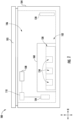
- FIG. 1 provides a side plan view of an ice making appliance 100, including an ice making assembly 102.
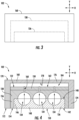
- FIG. 2 provides an elevation view of ice making assembly 102.
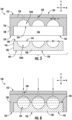
- FIG. 3 provides a cross-sectional elevation view of a portion of ice making assembly 102.
- FIGS. 5 through 8 provide various views of ice making assembly 102 (or portions thereof) before, during, and after an ice making process.
- ice making appliance 100 includes a cabinet 104 (e.g., insulated housing) and defines a mutually orthogonal vertical direction V, lateral direction, and transverse direction.
- the lateral direction and transverse direction may be generally understood to be horizontal directions H.
- cabinet 104 defines one or more chilled chambers, such as a freezer chamber 106.
- ice making appliance 100 is understood to be formed as, or as part of, a stand-alone freezer appliance. It is recognized, however, that additional or alternative embodiments may be provided within the context of other refrigeration appliances.
- a refrigerator appliance e.g., a top mount refrigerator appliance, a bottom mount refrigerator appliance, a side-by-side style refrigerator appliance, etc.
- a freezer chamber e.g., a refrigerator appliance that includes a freezer chamber.
- Ice making appliance 100 generally includes an ice making assembly 102 on or within freezer chamber 106.
- ice making appliance 100 includes a door 105 that is rotatably attached to cabinet 104 (e.g., at a top portion of the cabinet 104).
- door 105 may selectively cover an opening defined by cabinet 104.
- door 105 may rotate on cabinet 104 between an open position (not pictured) permitting access to freezer chamber 106 and a closed position ( FIG. 1 ) restricting access to freezer chamber 106.
- a user interface panel 108 may be provided for controlling the mode of operation.
- user interface panel 108 may include a plurality of user inputs (not labeled), such as a touchscreen or button interface, for selecting a desired mode of operation.
- Operation of ice making appliance 100 can be regulated by a controller 110 that is operatively coupled to or in wireless communication with user interface panel 108 or various other components, as will be described below.
- User interface panel 108 provides selections for user manipulation of the operation of ice making appliance 100 such as (e.g., selections regarding chamber temperature, ice making speed, or other various options).
- controller 110 may operate various components of the ice making appliance 100 or ice making assembly 102.
- Controller 110 may include a memory (e.g., non-transitive media) and one or more microprocessors, CPUs or the like, such as general or special purpose microprocessors operable to execute programming instructions or micro-control code associated with operation of ice making appliance 100.
- the memory may represent random access memory such as DRAM, or read only memory such as ROM or FLASH.
- the processor executes programming instructions stored in memory.
- the memory may be a separate component from the processor or may be included onboard within the processor.
- controller 110 may be constructed without using a microprocessor (e.g., using a combination of discrete analog or digital logic circuitry; such as switches, amplifiers, integrators, comparators, flip-flops, AND gates, and the like) to perform control functionality instead of relying upon software.
- a microprocessor e.g., using a combination of discrete analog or digital logic circuitry; such as switches, amplifiers, integrators, comparators, flip-flops, AND gates, and the like
- Controller 110 may be positioned in a variety of locations throughout ice making appliance 100. In optional embodiments, controller 110 is located within the user interface panel 108. In other embodiments, the controller 110 may be positioned at any suitable location within ice making appliance 100, such as for example within cabinet 104. Input/output ("I/O") signals may be routed between controller 110 and various operational components of ice making appliance 100. For example, user interface panel 108 may be in operable communication with controller 110 via one or more signal lines or shared communication busses.
- controller 110 may be in communication with the various components of appliance 100 and may control operation of the various components.
- various valves, switches, sealed cooling systems etc. may be actuatable based on commands from the controller 110 (e.g., based on one or temperature signals received from a temperature sensor within appliance 100, as would be understood).
- user interface panel 108 may additionally be in communication with the controller 110.
- the various operations may occur based on user input or automatically through controller 110 instruction.
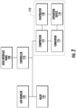
- ice making appliance 100 includes a sealed cooling system 112 for executing a vapor compression cycle for cooling ice making assembly 102 or air within ice making appliance 100 (e.g., within freezer chamber 106).
- Sealed cooling system 112 includes a compressor 114, a condenser 116, an expansion device 118, and an evaporator 120 connected in fluid series and charged with a refrigerant.
- sealed cooling system 112 may include additional components (e.g., at least one additional evaporator, compressor, expansion device, or condenser).
- at least one component e.g., evaporator 120
- evaporator 120 is provided in thermal communication with freezer chamber 106 to cool the air or environment within freezer chamber 106.
- evaporator 120 is mounted within freezer chamber 106, as generally illustrated in FIG. 1 . It is noted that although evaporator 120 is shown as spaced apart from ice making assembly 102, alternative embodiments may include ice making assembly 102 on or in contact with evaporator 120. For instance, ice making assembly 102 may be placed on top of evaporator 120, as would be understood in light of the present disclosure.
- gaseous refrigerant flows into compressor 114, which operates to increase the pressure of the refrigerant.
- This compression of the refrigerant raises the refrigerant temperature, which is lowered by passing the gaseous refrigerant through condenser 116.
- condenser 116 heat exchange (e.g., with ambient air takes place) to cool the refrigerant and cause the refrigerant to condense to a liquid state.
- Expansion device 118 receives liquid refrigerant from condenser 116. From expansion device 118, the liquid refrigerant enters evaporator 120. Upon exiting expansion device 118 and entering evaporator 120, the liquid refrigerant drops in pressure and vaporizes. Due to the pressure drop and phase change of the refrigerant, evaporator 120 is cool relative to freezer chamber 106. As such, cooled air is produced and refrigerates freezer chamber 106. Thus, evaporator 120 is a heat exchanger which transfers heat (e.g., from air passing over evaporator 120 to refrigerant flowing through evaporator 120).
- heat exchanger transfers heat (e.g., from air passing over evaporator 120 to refrigerant flowing through evaporator 120).
- ice making appliance 100 may include a valve 122 for regulating a flow of liquid water to ice making assembly 102 from a suitable water source (e.g., on-board water tank or municipal water source).
- a suitable water source e.g., on-board water tank or municipal water source.
- valve 122 is selectively adjustable between an open configuration and a closed configuration. In the open configuration, valve 122 may permit a flow of liquid water to ice making assembly 102. Conversely, in the closed configuration, valve 122 may hinder the flow of ice making assembly 102.
- ice making appliance 100 also includes an air handler 124 mounted within (or otherwise in fluid communication with) freezer chamber 106.
- Air handler 124 may be operable to urge a flow of chilled air (i.e., active airflow) within freezer chamber 106.
- air handler 124 can be any suitable device for moving air.
- air handler 124 can be an axial fan or a centrifugal fan.
- air handler 124 is in operable (e.g., electrical or wireless) communication with controller 110 (e.g., to be controlled by the same).
- ice making assembly 102 includes a separable mold body 130 that defines one or more mold cavities 134 in which water may be received and ice cubes or billets (e.g., solid masses or blocks of ice) may be formed. It is noted that although a single exemplary mold cavity 134 is described below, a plurality of discrete (e.g., horizontally spaced) mold cavities 134 may be provided, as shown.
- ice making assembly 102 may be selectively placed or received within freezer chamber 106.
- ice making assembly 102 e.g., the entirety of ice making assembly 102 or, alternatively, a sub portion thereof
- ice making assembly 102 may be removably positioned within freezer chamber 106 such that a user can selectively place ice making assembly 102 within freezer chamber 106 (e.g., during ice making operations) and remove ice making assembly 102 from freezer chamber 106 (e.g., to remove frozen ice cubes or billets from ice making assembly 102) as desired.
- separable mold body 130 includes a conductive ice mold 136 and an insulator ice mold 138 that is selectively or removably disposed on conductive ice mold 136.
- Conductive ice mold 136 extends along the vertical direction V between a top conductive mold end 140 and a bottom conductive mold end 142. Between these ends, conductive ice mold 136 defines at least a portion of mold cavity 134 (e.g., lower mold cavity 134A) and has a vertical opening 144 to the same.
- a conductive sidewall 146 may extend (e.g., vertically) between the top conductive mold end 140 and the bottom conductive mold end 142.
- Vertical opening 144 may be defined radially inward from conductive sidewall 146.
- conductive sidewall 146 may radially enclose vertical opening 144 or lower mold cavity 134A.
- vertical opening 144 is defined at top conductive mold end 140.
- Lower mold cavity 134A may extend downward from top conductive mold end 140 and terminate above bottom conductive mold end 142.
- conductive ice mold 136 may define lower mold cavity 134A as a concave (e.g., hemispherical) recess that is upwardly open along the vertical direction V to hold or receive water (e.g., flowing vertically from above vertical opening 144).
- a conductive bottom wall 148 may extend (e.g., horizontally) below or beneath mold cavity 134 (e.g., lower mold cavity 134A). For instance, conductive bottom wall 148 may extend along the bottom conductive mold end 142. In some embodiments, conductive bottom wall 148 (or bottom conductive mold end 142, generally) defines an exposed surface 150 directed away from mold cavity 134. Exposed surface 150 may thus extend (e.g., horizontally) along the bottom conductive mold end 142. Additionally or alternatively, exposed surface 150 may be defined opposite of the vertical opening 144. In certain embodiments, the vertical opening 144 defines the sole opening (e.g., for water) to lower mold cavity 134A. Additionally or alternatively, bottom conductive mold end 142 may be sealed such that water is prevented from entering or escaping conductive mold body 130 through conductive bottom wall 148 or bottom conductive mold end 142, generally.
- insulator ice mold 138 may be selectively received (e.g., to cover or enclose mold cavity 134 at the vertical opening 144). As shown, insulator ice mold 138 extends (e.g., vertically) between a top insulator mold end 152 and a bottom insulator mold end 154. For instance, insulator ice mold 138 may include an insulator sidewall 156 extending (e.g., vertically) between the top insulator mold end 152 and the bottom insulator mold end 154. An insulator top wall 158 may extend (e.g., horizontally) across insulator sidewall 156.
- insulator ice mold 138 may define an internal water passage 160.
- internal water passage 160 extends above the mold cavity 134 (e.g., through insulator top wall 158) in fluid communication therewith.
- Internal water passage 160 may extend from mold cavity 134 and to or through an upper surface 162 of insulator ice mold 138, which is directed away from the mold cavity 134.
- mold cavity 134 expands from and is wider than internal water passage 160.
- the mold cavity 134 (e.g., at the vertical opening 144) defines a maximum horizontal width D1 that is greater than a maximum horizontal width D2 defined by the internal water passage 160.
- water may thus be permitted to flow through internal water passage 160 to/from mold cavity 134 (e.g., when insulator ice mold 138 is received on conductive ice mold 136).
- insulator ice mold 138 further defines at least a portion of mold cavity 134.
- insulator ice mold 138 may define an upper mold cavity 134B.
- upper mold cavity 134B may be defined within insulator top wall 158 or otherwise be disposed radially inward from insulator sidewall 156.
- Upper mold cavity 134B may be disposed directly beneath internal water passage 160.
- upper mold cavity 134B may terminate at a cavity opening 164.
- upper mold cavity 134B may extend downward from internal water passage 160 and terminate above lower bottom insulator mold end 154.
- upper mold cavity 134B may be selectively mated with the lower mold cavity 134A to form a unitary ice billet therein.
- insulator ice mold 138 may define upper mold cavity 134B as a concave (e.g., hemispherical) recess that is downward open along the vertical direction V to hold or receive water with lower mold cavity 134A (e.g., flowing vertically through internal water passage 160).
- ice billets formed within mold cavity may emerge as solid (e.g., clear) spheres.
- insulator ice mold 138 is able to selectively cover at least a portion of conductive ice mold 136 (e.g., at vertical opening 144). In some embodiments, insulator ice mold 138 is further able to receive or enclose at least a portion of conductive ice mold 136.
- Insulator sidewall 156 may be disposed radially outward from conductive ice mold 136. Specifically, insulator sidewall 156 may be positioned radially outward from conductive sidewall 146 or the exposed surface 150. In some such embodiments, insulator sidewall 156 defines a mated opening 165 to an insulating cavity 166. Insulating cavity 166 may be defined beneath insulator top wall 158 or upper mold cavity 134B.
- conductive ice mold 136 may be received within insulating cavity 166.
- conductive ice mold 136 nests within insulating cavity 166 such that insulator sidewall 156 covers conductive sidewall 146.
- Insulating cavity 166 may extend from the top conductive mold end 140 to the bottom conductive mold end 142 (e.g., below the upper mold cavity 134B).
- insulator sidewall 156 may extend (e.g., fully or uninterrupted) from top conductive mold end 140 to bottom conductive mold end 142 and, thus, selectively cover conductive sidewall 146.
- the exposed surface 150 may be held uncovered within or across the mated opening 165.
- ice making assembly 102 includes an external insulator jacket 168.
- external insulator jacket 168 is selectively received on the insulator ice mold 138.
- external insulator jacket 168 may cover the internal water passage 160 (e.g., to generally block internal water passage 160 from a user's view or the ambient environment).
- external insulator jacket 168 extends (e.g., vertically) between a top jacket end 170 and a bottom jacket end 172.
- external insulator jacket 168 may include a jacket sidewall 174 extending (e.g., vertically) between the top jacket end 170 and the bottom jacket end 172.
- An upper jacket wall 176 may extend (e.g., horizontally) across insulator sidewall 156.
- An internal surface 178 of upper jacket wall 176 may be directed (e.g., downward) toward insulator ice mold 138.
- external insulator jacket 168 is able to selectively cover at least a portion of insulator ice mold 138 (e.g., at internal water passage 160). In some embodiments, external insulator jacket 168 is further able to receive or enclose at least a portion of insulator ice mold 138. At least a portion of jacket sidewall 174 may be disposed radially outward from insulator ice mold 138. Specifically, jacket sidewall 174 may be positioned radially outward from insulator sidewall 156. Additionally or alternatively, jacket sidewall 174 may be positioned radially outward from the exposed surface 150 of conductive ice mold 136.
- jacket sidewall 174 defines a jacket opening 180 for an enclosing cavity 182, which external insulator jacket 168 also defines.
- enclosing cavity 182 may be defined beneath upper jacket wall 176. At least a portion of insulator ice mold 138 may be received within enclosing cavity 182.
- insulator ice mold 138 nests within enclosing cavity 182 such that jacket sidewall 174 covers insulator sidewall 156.
- Enclosing cavity 182 may extend from the top insulator mold end 152 to the bottom insulator mold end 154.
- jacket sidewall 174 When assembled, jacket sidewall 174 may extend (e.g., fully or uninterrupted) from top jacket end 170 to bottom jacket end 172 and, thus, selectively cover insulator sidewall 156. Additionally or alternatively, the exposed surface 150 may be held uncovered within the jacket opening 180.
- external insulator jacket 168 defines an excess water chamber 184 with insulator ice mold 138.
- a vertical gap or distance may be maintained between the upper surface 162 of the insulator ice mold 138 and the internal surface 178 of the external insulator jacket 168.
- the excess water chamber 184 may be defined within this vertical gap between the upper surface 162 of the insulator ice mold 138 and the internal surface 178 of the external insulator jacket 168.
- the internal water passage 160 may extend to the excess water chamber 184 and, thus, be in fluid communication between the excess water chamber 184 and the mold cavity 134.
- conductive ice mold 136 is formed of a different material than insulator ice mold 138.
- conductive ice mold 136 may have a (e.g., first) thermal coefficient that is greater than a (e.g., second) thermal coefficient of the insulator ice mold 138.
- conductive ice mold 136 may be a metal conductive ice mold while insulator ice mold 138 may be a non-metallic insulator ice mold.
- conductive ice mold 136 may be formed of a suitable heatconductive metal for facilitating the removal of heat from mold cavity 134, such as aluminum or stainless steel (e.g., including combinations or alloys thereof).
- insulator ice mold 138 may be formed of a suitable heat-insulating polymer for restricting heat transfer to one or more portions of mold cavity 134, such as silicone, polycarbonate or polyethylene (e.g., including combinations or variations thereof).
- the conductive ice mold 136 is also formed from a different material than the external insulator jacket 168.
- the first thermal coefficient of the conductive ice mold 136 may be greater than a (e.g., third) thermal coefficient of the external insulator jacket 168.
- external insulator jacket 168 may formed of a suitable heat-insulating polymer for restricting heat transfer to one or more portions of mold cavity 134, such as silicone, polycarbonate or polyethylene (e.g., including combinations or variations thereof).
- the material of the external insulator jacket 168 may be the same as the insulator ice mold 138.
- the material of the external insulator jacket 168 may be the same as the insulator ice mold 138.
- the third and second thermal coefficients may be substantially equal or, alternatively, different (e.g., such that the third thermal coefficient is less than the second thermal coefficient).
- conductive ice mold 136, insulator ice mold 138, or external insulator jacket 168 may each be formed as a discrete, unitary or integral component.
- conductive ice mold 136 may be a solid, unitary member of a first material.
- insulator ice mold 138 may be a solid, unitary member of a second material.
- external insulator jacket 168 may be a solid, unitary member of a third material.
- FIGS. 5 through 8 exemplary steps for using ice making assembly 102 are illustrated (e.g., by showing ice making assembly in various stages).
- insulator ice mold 138 may be selectively mated onto conductive ice mold 136 such that conductive ice mold 136 is received within insulator ice mold 138, thereby assembling separable mold body 130.
- water may be provided to mold cavity 134 (e.g., through internal water passage 160).
- external insulator jacket 168 is mated onto insulator ice mold 138 such that insulator ice mold 138 and conductive ice mold 136 are received within external insulator jacket 168.
- heat may be conducted from mold cavity 134 (e.g., within freezer chamber 106- FIG. 1 ) through conductive ice mold 136 and the exposed surface 150, as illustrated in FIG. 7 .
- the conduction of heat from mold cavity 134 may cause an ice billet to form within mold cavity 134 as water freezes from the bottom of mold cavity 134 and notably forces impurities upward away from mold (e.g., with unfrozen water to excess water chamber 184 through internal water passage 160).
Landscapes
- Engineering & Computer Science (AREA)
- Physics & Mathematics (AREA)
- Mechanical Engineering (AREA)
- Thermal Sciences (AREA)
- General Engineering & Computer Science (AREA)
- Production, Working, Storing, Or Distribution Of Ice (AREA)
Abstract
Description
- The present subject matter relates generally to ice making assemblies and methods, and more particularly to assemblies and methods for making substantially clear ice.
- In domestic and commercial applications, ice is often formed as solid cubes, such as crescent cubes or generally rectangular blocks. The shape of such cubes is often dictated by the environment during a freezing process. For instance, an ice maker can receive liquid water, and such liquid water can freeze within the ice maker to form ice cubes. In particular, certain ice makers include a freezing mold that defines a plurality of cavities. The plurality of cavities can be filled with liquid water, and such liquid water can freeze within the plurality of cavities to form solid ice cubes.
- In typical ice making appliances, water in the cavities begins to freeze and solidify first from its sides and outer surfaces (including a top water surface that may be directly exposed to freezing air), and then in and through the remaining volume of water occupying the cavity. In other words, top and side surfaces of an ice cube freeze first. However, impurities and gases contained within the water to be frozen may be trapped in a solidified ice cube during the freezing process. For example, impurities and gases may be trapped near the center or the bottom surface of the ice cube, due to their inability to escape and as a result of the freezing liquid to solid phase change of the ice cube surfaces. Separate from or in addition to the trapped impurities and gases, a dull or cloudy finish may form on the exterior surfaces of an ice cube (e.g., during rapid freezing of the ice cube). Generally, a cloudy or opaque ice cube is the resulting product of typical ice making appliances.
- Although typical ice cubes may be suitable for a number uses, such as temporary cold storage and rapid cooling of liquids in a wide range of sizes, they may present a number of disadvantages. As an example, impurities and gases trapped within an ice cube may impart undesirable flavors into a beverage being cooled (i.e., a beverage in which the ice cube is placed) as the ice cube melts. Such impurities and gases may also cause an ice cube to melt unevenly or faster (e.g., by increasing the exposed surface area of the ice cube). Evenly-distributed or slow melting of ice may be especially desirable in certain liquors or cocktails. Additionally or alternatively, it has been found that substantially clear ice cubes (e.g., free of any visible impurities or dull finish) may provide a unique or upscale impression for the user. Past attempts to solve such problems have generally been undesirably slow, complex, or have resulted in excessive unfrozen water, which complicates retrieval of finished cubes.
- Accordingly, further improvements in the field of ice making would be desirable. In particular, it may be desirable to provide an appliance or methods for rapidly and reliably producing substantially clear ice (e.g., without being undesirably complex or leaving significant volumes of unfrozen water with the clear ice).
- Aspects and advantages of the invention will be set forth in part in the following description, or may be obvious from the description, or may be learned through practice of the invention.
- In one exemplary aspect of the present disclosure, an ice making assembly is provided. The ice making assembly may include a conductive ice mold, an insulator ice mold, and an external insulator jacket. The conductive ice mold may extend along a vertical direction between a top conductive mold end and a bottom conductive mold end. The conductive ice mold may define a mold cavity having a vertical opening at the top conductive mold end. The insulator ice mold may be selectively received on the conductive ice mold and cover the vertical opening. The insulator ice mold may define an internal water passage extending above the mold cavity in fluid communication with the mold cavity. The external insulator jacket may be selectively received on the insulator ice mold and cover the internal water passage.
- In another exemplary aspect of the present disclosure, an ice making assembly is provided. The ice making assembly may include a metal conductive ice mold, a non-metallic insulator ice mold, and an external insulator jacket. The metal conductive ice mold may extend along a vertical direction between a top conductive mold end and a bottom conductive mold end. The metal conductive ice mold may define a mold cavity having a vertical opening at the top conductive mold end. The metal conductive ice mold may further define an exposed surface extending along the bottom conductive mold end opposite of the vertical opening. The non-metallic insulator ice mold may be selectively received on the metal conductive ice mold radially outward from the exposed surface and cover the vertical opening. The non-metallic insulator ice mold may define an internal water passage extending above the mold cavity in fluid communication with the mold cavity. The external insulator jacket may be selectively received on the non-metallic insulator ice mold radially outward from the exposed surface and the non-metallic insulator ice mold. The external insulator jacket may cover the internal water passage.
- These and other features, aspects and advantages of the present invention will become better understood with reference to the following description and appended claims. The accompanying drawings, which are incorporated in and constitute a part of this specification, illustrate embodiments of the invention and, together with the description, serve to explain the principles of the invention.
- A full and enabling disclosure of the present invention, including the best mode thereof, directed to one of ordinary skill in the art, is set forth in the specification, which makes reference to the appended figures.
-
FIG. 1 provides a side plan view of an ice making appliance according to exemplary embodiments of the present disclosure. -
FIG. 2 provides a schematic view of an ice making appliance according to exemplary embodiments of the present disclosure. -
FIG. 3 provides an elevation view of a portion of an ice making assembly according to exemplary embodiments of the present disclosure. -
FIG. 4 provides a cross-sectional elevation view of the exemplary ice making assembly ofFIG. 3 . -
FIG. 5 provides a cross-sectional elevation view of a portion of the exemplary ice making assembly ofFIG. 3 , prior to receiving water therein. -
FIG. 6 provides a cross-sectional elevation view of a portion of the exemplary ice making assembly ofFIG. 3 , while receiving water therein. -
FIG. 7 provides a cross-sectional elevation view of the exemplary ice making assembly ofFIG. 3 , during a freezing process to form ice billets therein. -
FIG. 8 provides a cross-sectional elevation view of a portion of the exemplary ice making assembly ofFIG. 3 , following the freezing of ice billets therein. - Reference now will be made in detail to embodiments of the invention, one or more examples of which are illustrated in the drawings. Each example is provided by way of explanation of the invention, not limitation of the invention. In fact, it will be apparent to those skilled in the art that various modifications and variations can be made in the present invention without departing from the scope of the invention. For instance, features illustrated or described as part of one embodiment can be used with another embodiment to yield a still further embodiment. Thus, it is intended that the present invention covers such modifications and variations as come within the scope of the appended claims and their equivalents.
- As used herein, the terms "first," "second," and "third" may be used interchangeably to distinguish one component from another and are not intended to signify location or importance of the individual components. The terms "includes" and "including" are intended to be inclusive in a manner similar to the term "comprising." Similarly, the term "or" is generally intended to be inclusive (i.e., "A or B" is intended to mean "A or B or both"). In addition, here and throughout the specification and claims, range limitations may be combined or interchanged. Such ranges are identified and include all the sub-ranges contained therein unless context or language indicates otherwise. For example, all ranges disclosed herein are inclusive of the endpoints, and the endpoints are independently combinable with each other. The singular forms "a," "an," and "the" include plural references unless the context clearly dictates otherwise.
- Approximating language, as used herein throughout the specification and claims, may be applied to modify any quantitative representation that could permissibly vary without resulting in a change in the basic function to which it is related. Accordingly, a value modified by a term or terms, such as "generally," "about," "approximately," and "substantially," are not to be limited to the precise value specified. In at least some instances, the approximating language may correspond to the precision of an instrument for measuring the value, or the precision of the methods or machines for constructing or manufacturing the components or systems. For example, the approximating language may refer to being within a 10 percent margin (i.e., including values within ten percent greater or less than the stated value). In this regard, for example, when used in the context of an angle or direction, such terms include within ten degrees greater or less than the stated angle or direction (e.g., "generally vertical" includes forming an angle of up to ten degrees in any direction, such as clockwise or counterclockwise, with the vertical direction V).
- The word "exemplary" is used herein to mean "serving as an example, instance, or illustration." In addition, references to "an embodiment" or "one embodiment" does not necessarily refer to the same embodiment, although it may. Any implementation described herein as "exemplary" or "an embodiment" is not necessarily to be construed as preferred or advantageous over other implementations. Moreover, each example is provided by way of explanation of the invention, not limitation of the invention. In fact, it will be apparent to those skilled in the art that various modifications and variations can be made in the present invention without departing from the scope of the invention. For instance, features illustrated or described as part of one embodiment can be used with another embodiment to yield a still further embodiment. Thus, it is intended that the present invention covers such modifications and variations as come within the scope of the appended claims and their equivalents.
- Turning now to the figures,
FIG. 1 provides a side plan view of anice making appliance 100, including anice making assembly 102.FIG. 2 provides an elevation view ofice making assembly 102.FIG. 3 provides a cross-sectional elevation view of a portion ofice making assembly 102.FIGS. 5 through 8 provide various views of ice making assembly 102 (or portions thereof) before, during, and after an ice making process. - Generally,
ice making appliance 100 includes a cabinet 104 (e.g., insulated housing) and defines a mutually orthogonal vertical direction V, lateral direction, and transverse direction. The lateral direction and transverse direction may be generally understood to be horizontal directions H. As shown,cabinet 104 defines one or more chilled chambers, such as afreezer chamber 106. In certain embodiments, such as those illustrated byFIG. 1 ,ice making appliance 100 is understood to be formed as, or as part of, a stand-alone freezer appliance. It is recognized, however, that additional or alternative embodiments may be provided within the context of other refrigeration appliances. For instance, the benefits of the present disclosure may apply to any type or style of a refrigerator appliance (e.g., a top mount refrigerator appliance, a bottom mount refrigerator appliance, a side-by-side style refrigerator appliance, etc.) that includes a freezer chamber. Consequently, the description set forth herein is for illustrative purposes only and is not intended to be limiting in any aspect to any particular chamber or appliance configuration. -
Ice making appliance 100 generally includes anice making assembly 102 on or withinfreezer chamber 106. In some embodiments,ice making appliance 100 includes adoor 105 that is rotatably attached to cabinet 104 (e.g., at a top portion of the cabinet 104). As would be understood,door 105 may selectively cover an opening defined bycabinet 104. For instance,door 105 may rotate oncabinet 104 between an open position (not pictured) permitting access tofreezer chamber 106 and a closed position (FIG. 1 ) restricting access tofreezer chamber 106. - A
user interface panel 108 may be provided for controlling the mode of operation. For example,user interface panel 108 may include a plurality of user inputs (not labeled), such as a touchscreen or button interface, for selecting a desired mode of operation. Operation ofice making appliance 100 can be regulated by acontroller 110 that is operatively coupled to or in wireless communication withuser interface panel 108 or various other components, as will be described below.User interface panel 108 provides selections for user manipulation of the operation ofice making appliance 100 such as (e.g., selections regarding chamber temperature, ice making speed, or other various options). In response to user manipulation ofuser interface panel 108, or one or more sensor signals,controller 110 may operate various components of theice making appliance 100 orice making assembly 102. -
Controller 110 may include a memory (e.g., non-transitive media) and one or more microprocessors, CPUs or the like, such as general or special purpose microprocessors operable to execute programming instructions or micro-control code associated with operation ofice making appliance 100. The memory may represent random access memory such as DRAM, or read only memory such as ROM or FLASH. In one embodiment, the processor executes programming instructions stored in memory. The memory may be a separate component from the processor or may be included onboard within the processor. Alternatively,controller 110 may be constructed without using a microprocessor (e.g., using a combination of discrete analog or digital logic circuitry; such as switches, amplifiers, integrators, comparators, flip-flops, AND gates, and the like) to perform control functionality instead of relying upon software. -
Controller 110 may be positioned in a variety of locations throughoutice making appliance 100. In optional embodiments,controller 110 is located within theuser interface panel 108. In other embodiments, thecontroller 110 may be positioned at any suitable location withinice making appliance 100, such as for example withincabinet 104. Input/output ("I/O") signals may be routed betweencontroller 110 and various operational components ofice making appliance 100. For example,user interface panel 108 may be in operable communication withcontroller 110 via one or more signal lines or shared communication busses. - As illustrated,
controller 110 may be in communication with the various components ofappliance 100 and may control operation of the various components. For example, various valves, switches, sealed cooling systems etc. may be actuatable based on commands from the controller 110 (e.g., based on one or temperature signals received from a temperature sensor withinappliance 100, as would be understood). As discussed,user interface panel 108 may additionally be in communication with thecontroller 110. Thus, the various operations may occur based on user input or automatically throughcontroller 110 instruction. - In some embodiments,
ice making appliance 100 includes a sealedcooling system 112 for executing a vapor compression cycle for coolingice making assembly 102 or air within ice making appliance 100 (e.g., within freezer chamber 106).Sealed cooling system 112 includes acompressor 114, acondenser 116, anexpansion device 118, and anevaporator 120 connected in fluid series and charged with a refrigerant. As will be understood by those skilled in the art, sealedcooling system 112 may include additional components (e.g., at least one additional evaporator, compressor, expansion device, or condenser). Moreover, at least one component (e.g., evaporator 120) is provided in thermal communication withfreezer chamber 106 to cool the air or environment withinfreezer chamber 106. Optionally,evaporator 120 is mounted withinfreezer chamber 106, as generally illustrated inFIG. 1 . It is noted that althoughevaporator 120 is shown as spaced apart fromice making assembly 102, alternative embodiments may includeice making assembly 102 on or in contact withevaporator 120. For instance,ice making assembly 102 may be placed on top ofevaporator 120, as would be understood in light of the present disclosure. - Within sealed
cooling system 112, gaseous refrigerant flows intocompressor 114, which operates to increase the pressure of the refrigerant. This compression of the refrigerant raises the refrigerant temperature, which is lowered by passing the gaseous refrigerant throughcondenser 116. Withincondenser 116, heat exchange (e.g., with ambient air takes place) to cool the refrigerant and cause the refrigerant to condense to a liquid state. - Expansion device 118 (e.g., a mechanical valve, capillary tube, electronic expansion valve, or other restriction device) receives liquid refrigerant from
condenser 116. Fromexpansion device 118, the liquid refrigerant entersevaporator 120. Upon exitingexpansion device 118 and enteringevaporator 120, the liquid refrigerant drops in pressure and vaporizes. Due to the pressure drop and phase change of the refrigerant,evaporator 120 is cool relative tofreezer chamber 106. As such, cooled air is produced and refrigeratesfreezer chamber 106. Thus,evaporator 120 is a heat exchanger which transfers heat (e.g., from air passing overevaporator 120 to refrigerant flowing through evaporator 120). - Optionally,
ice making appliance 100 may include avalve 122 for regulating a flow of liquid water to ice makingassembly 102 from a suitable water source (e.g., on-board water tank or municipal water source). In such embodiments,valve 122 is selectively adjustable between an open configuration and a closed configuration. In the open configuration,valve 122 may permit a flow of liquid water to ice makingassembly 102. Conversely, in the closed configuration,valve 122 may hinder the flow ofice making assembly 102. - In certain embodiments,
ice making appliance 100 also includes anair handler 124 mounted within (or otherwise in fluid communication with)freezer chamber 106.Air handler 124 may be operable to urge a flow of chilled air (i.e., active airflow) withinfreezer chamber 106. Moreover,air handler 124 can be any suitable device for moving air. For example,air handler 124 can be an axial fan or a centrifugal fan. In some embodiments,air handler 124 is in operable (e.g., electrical or wireless) communication with controller 110 (e.g., to be controlled by the same). - Generally,
ice making assembly 102 includes aseparable mold body 130 that defines one ormore mold cavities 134 in which water may be received and ice cubes or billets (e.g., solid masses or blocks of ice) may be formed. It is noted that although a singleexemplary mold cavity 134 is described below, a plurality of discrete (e.g., horizontally spaced)mold cavities 134 may be provided, as shown. - During use,
ice making assembly 102 may be selectively placed or received withinfreezer chamber 106. For example, ice making assembly 102 (e.g., the entirety ofice making assembly 102 or, alternatively, a sub portion thereof) may be removably positioned withinfreezer chamber 106 such that a user can selectively placeice making assembly 102 within freezer chamber 106 (e.g., during ice making operations) and removeice making assembly 102 from freezer chamber 106 (e.g., to remove frozen ice cubes or billets from ice making assembly 102) as desired. - As shown,
separable mold body 130 includes aconductive ice mold 136 and aninsulator ice mold 138 that is selectively or removably disposed onconductive ice mold 136.Conductive ice mold 136 extends along the vertical direction V between a topconductive mold end 140 and a bottomconductive mold end 142. Between these ends,conductive ice mold 136 defines at least a portion of mold cavity 134 (e.g.,lower mold cavity 134A) and has avertical opening 144 to the same. For instance, aconductive sidewall 146 may extend (e.g., vertically) between the topconductive mold end 140 and the bottomconductive mold end 142.Vertical opening 144 may be defined radially inward fromconductive sidewall 146. In turn,conductive sidewall 146 may radially enclosevertical opening 144 orlower mold cavity 134A. In some embodiments,vertical opening 144 is defined at topconductive mold end 140.Lower mold cavity 134A may extend downward from topconductive mold end 140 and terminate above bottomconductive mold end 142. Optionally,conductive ice mold 136 may definelower mold cavity 134A as a concave (e.g., hemispherical) recess that is upwardly open along the vertical direction V to hold or receive water (e.g., flowing vertically from above vertical opening 144). - A
conductive bottom wall 148 may extend (e.g., horizontally) below or beneath mold cavity 134 (e.g.,lower mold cavity 134A). For instance, conductivebottom wall 148 may extend along the bottomconductive mold end 142. In some embodiments, conductive bottom wall 148 (or bottomconductive mold end 142, generally) defines an exposedsurface 150 directed away frommold cavity 134. Exposedsurface 150 may thus extend (e.g., horizontally) along the bottomconductive mold end 142. Additionally or alternatively, exposedsurface 150 may be defined opposite of thevertical opening 144. In certain embodiments, thevertical opening 144 defines the sole opening (e.g., for water) tolower mold cavity 134A. Additionally or alternatively, bottomconductive mold end 142 may be sealed such that water is prevented from entering or escapingconductive mold body 130 through conductivebottom wall 148 or bottomconductive mold end 142, generally. - On or around
conductive ice mold 136,insulator ice mold 138 may be selectively received (e.g., to cover or enclosemold cavity 134 at the vertical opening 144). As shown,insulator ice mold 138 extends (e.g., vertically) between a topinsulator mold end 152 and a bottominsulator mold end 154. For instance,insulator ice mold 138 may include aninsulator sidewall 156 extending (e.g., vertically) between the topinsulator mold end 152 and the bottominsulator mold end 154. An insulatortop wall 158 may extend (e.g., horizontally) acrossinsulator sidewall 156. Between topinsulator mold end 152 and bottominsulator mold end 154,insulator ice mold 138 may define aninternal water passage 160. Specifically,internal water passage 160 extends above the mold cavity 134 (e.g., through insulator top wall 158) in fluid communication therewith.Internal water passage 160 may extend frommold cavity 134 and to or through anupper surface 162 ofinsulator ice mold 138, which is directed away from themold cavity 134. Generally,mold cavity 134 expands from and is wider thaninternal water passage 160. In such embodiments, the mold cavity 134 (e.g., at the vertical opening 144) defines a maximum horizontal width D1 that is greater than a maximum horizontal width D2 defined by theinternal water passage 160. During use, water may thus be permitted to flow throughinternal water passage 160 to/from mold cavity 134 (e.g., wheninsulator ice mold 138 is received on conductive ice mold 136). - In some embodiments,
insulator ice mold 138 further defines at least a portion ofmold cavity 134. For instance,insulator ice mold 138 may define anupper mold cavity 134B. Optionally,upper mold cavity 134B may be defined within insulatortop wall 158 or otherwise be disposed radially inward frominsulator sidewall 156.Upper mold cavity 134B may be disposed directly beneathinternal water passage 160. Moreover,upper mold cavity 134B may terminate at acavity opening 164. In turn,upper mold cavity 134B may extend downward frominternal water passage 160 and terminate above lower bottominsulator mold end 154. As shown,upper mold cavity 134B may be selectively mated with thelower mold cavity 134A to form a unitary ice billet therein. Optionally,insulator ice mold 138 may defineupper mold cavity 134B as a concave (e.g., hemispherical) recess that is downward open along the vertical direction V to hold or receive water withlower mold cavity 134A (e.g., flowing vertically through internal water passage 160). In some such embodiments, ice billets formed within mold cavity may emerge as solid (e.g., clear) spheres. - Generally,
insulator ice mold 138 is able to selectively cover at least a portion of conductive ice mold 136 (e.g., at vertical opening 144). In some embodiments,insulator ice mold 138 is further able to receive or enclose at least a portion ofconductive ice mold 136.Insulator sidewall 156 may be disposed radially outward fromconductive ice mold 136. Specifically,insulator sidewall 156 may be positioned radially outward fromconductive sidewall 146 or the exposedsurface 150. In some such embodiments,insulator sidewall 156 defines a matedopening 165 to an insulatingcavity 166. Insulatingcavity 166 may be defined beneath insulatortop wall 158 orupper mold cavity 134B. At least a portion ofconductive ice mold 136 may be received within insulatingcavity 166. Optionally,conductive ice mold 136 nests within insulatingcavity 166 such thatinsulator sidewall 156 coversconductive sidewall 146. Insulatingcavity 166 may extend from the topconductive mold end 140 to the bottom conductive mold end 142 (e.g., below theupper mold cavity 134B). When assembled,insulator sidewall 156 may extend (e.g., fully or uninterrupted) from topconductive mold end 140 to bottomconductive mold end 142 and, thus, selectively coverconductive sidewall 146. Additionally or alternatively, the exposedsurface 150 may be held uncovered within or across the matedopening 165. - Along with
separable mold body 130,ice making assembly 102 includes anexternal insulator jacket 168. In particular,external insulator jacket 168 is selectively received on theinsulator ice mold 138. When assembled,external insulator jacket 168 may cover the internal water passage 160 (e.g., to generally blockinternal water passage 160 from a user's view or the ambient environment). As shown,external insulator jacket 168 extends (e.g., vertically) between atop jacket end 170 and abottom jacket end 172. For instance,external insulator jacket 168 may include ajacket sidewall 174 extending (e.g., vertically) between thetop jacket end 170 and thebottom jacket end 172. Anupper jacket wall 176 may extend (e.g., horizontally) acrossinsulator sidewall 156. Aninternal surface 178 ofupper jacket wall 176 may be directed (e.g., downward) towardinsulator ice mold 138. - Generally,
external insulator jacket 168 is able to selectively cover at least a portion of insulator ice mold 138 (e.g., at internal water passage 160). In some embodiments,external insulator jacket 168 is further able to receive or enclose at least a portion ofinsulator ice mold 138. At least a portion ofjacket sidewall 174 may be disposed radially outward frominsulator ice mold 138. Specifically,jacket sidewall 174 may be positioned radially outward frominsulator sidewall 156. Additionally or alternatively,jacket sidewall 174 may be positioned radially outward from the exposedsurface 150 ofconductive ice mold 136. In some such embodiments,jacket sidewall 174 defines ajacket opening 180 for anenclosing cavity 182, whichexternal insulator jacket 168 also defines. Specifically, enclosingcavity 182 may be defined beneathupper jacket wall 176. At least a portion ofinsulator ice mold 138 may be received within enclosingcavity 182. Optionally,insulator ice mold 138 nests within enclosingcavity 182 such thatjacket sidewall 174 coversinsulator sidewall 156. Enclosingcavity 182 may extend from the topinsulator mold end 152 to the bottominsulator mold end 154. When assembled,jacket sidewall 174 may extend (e.g., fully or uninterrupted) fromtop jacket end 170 tobottom jacket end 172 and, thus, selectively coverinsulator sidewall 156. Additionally or alternatively, the exposedsurface 150 may be held uncovered within thejacket opening 180. - In certain embodiment,
external insulator jacket 168 defines anexcess water chamber 184 withinsulator ice mold 138. For instance, a vertical gap or distance may be maintained between theupper surface 162 of theinsulator ice mold 138 and theinternal surface 178 of theexternal insulator jacket 168. In particular, theexcess water chamber 184 may be defined within this vertical gap between theupper surface 162 of theinsulator ice mold 138 and theinternal surface 178 of theexternal insulator jacket 168. As shown, theinternal water passage 160 may extend to theexcess water chamber 184 and, thus, be in fluid communication between theexcess water chamber 184 and themold cavity 134. - Generally, the various components of
ice making assembly 102 may each be formed from any suitable material. Nonetheless, the materials used to form discrete components may be distinct. In particular,conductive ice mold 136 is formed of a different material thaninsulator ice mold 138. Moreover,conductive ice mold 136 may have a (e.g., first) thermal coefficient that is greater than a (e.g., second) thermal coefficient of theinsulator ice mold 138. For instance,conductive ice mold 136 may be a metal conductive ice mold whileinsulator ice mold 138 may be a non-metallic insulator ice mold. Thus,conductive ice mold 136 may be formed of a suitable heatconductive metal for facilitating the removal of heat frommold cavity 134, such as aluminum or stainless steel (e.g., including combinations or alloys thereof). Additionally or alternatively,insulator ice mold 138 may be formed of a suitable heat-insulating polymer for restricting heat transfer to one or more portions ofmold cavity 134, such as silicone, polycarbonate or polyethylene (e.g., including combinations or variations thereof). - In certain embodiments, the
conductive ice mold 136 is also formed from a different material than theexternal insulator jacket 168. Specifically, the first thermal coefficient of theconductive ice mold 136 may be greater than a (e.g., third) thermal coefficient of theexternal insulator jacket 168. For instance,external insulator jacket 168 may formed of a suitable heat-insulating polymer for restricting heat transfer to one or more portions ofmold cavity 134, such as silicone, polycarbonate or polyethylene (e.g., including combinations or variations thereof). The material of theexternal insulator jacket 168 may be the same as theinsulator ice mold 138. Alternatively, the material of theexternal insulator jacket 168 may be the same as theinsulator ice mold 138. The third and second thermal coefficients may be substantially equal or, alternatively, different (e.g., such that the third thermal coefficient is less than the second thermal coefficient). - Optionally,
conductive ice mold 136,insulator ice mold 138, orexternal insulator jacket 168 may each be formed as a discrete, unitary or integral component. As an example,conductive ice mold 136 may be a solid, unitary member of a first material. As an additional or alternative example,insulator ice mold 138 may be a solid, unitary member of a second material. As another additional or alternative example,external insulator jacket 168 may be a solid, unitary member of a third material. - Turning especially to
FIGS. 5 through 8 , exemplary steps for usingice making assembly 102 are illustrated (e.g., by showing ice making assembly in various stages). As shown inFIG. 5 , prior to providing water tomold cavity 134,insulator ice mold 138 may be selectively mated ontoconductive ice mold 136 such thatconductive ice mold 136 is received withininsulator ice mold 138, thereby assemblingseparable mold body 130. As shown inFIG. 6 , onceseparable mold body 130 is assembled, water may be provided to mold cavity 134 (e.g., through internal water passage 160). After water fillsmold cavity 134,external insulator jacket 168 is mated ontoinsulator ice mold 138 such thatinsulator ice mold 138 andconductive ice mold 136 are received withinexternal insulator jacket 168. Moreover, heat may be conducted from mold cavity 134 (e.g., within freezer chamber 106-FIG. 1 ) throughconductive ice mold 136 and the exposedsurface 150, as illustrated inFIG. 7 . The conduction of heat frommold cavity 134 may cause an ice billet to form withinmold cavity 134 as water freezes from the bottom ofmold cavity 134 and notably forces impurities upward away from mold (e.g., with unfrozen water toexcess water chamber 184 through internal water passage 160). Notably impurities and excess water may be carried away frommold cavity 134 to avoid the formation of a cloudy ice billet withinmold 134. As shown inFIG. 8 , after an ice billet is formed,external insulator jacket 168 andinsulator ice mold 138 may be removed fromconductive ice mold 136, allowing a user to access and remove one or more frozen ice billets. - This written description uses examples to disclose the invention, including the best mode, and also to enable any person skilled in the art to practice the invention, including making and using any devices or systems and performing any incorporated methods. The patentable scope of the invention is defined by the claims, and may include other examples that occur to those skilled in the art. Such other examples are intended to be within the scope of the claims if they include structural elements that do not differ from the literal language of the claims, or if they include equivalent structural elements with insubstantial differences from the literal languages of the claims.
Claims (19)
- An ice making assembly comprising:a conductive ice mold extending along a vertical direction between a top conductive mold end and a bottom conductive mold end, the conductive ice mold defining a mold cavity having a vertical opening at the top conductive mold end;an insulator ice mold selectively received on the conductive ice mold and covering the vertical opening, the insulator ice mold defining an internal water passage extending above the mold cavity in fluid communication with the mold cavity; andan external insulator jacket selectively received on the insulator ice mold and covering the internal water passage.
- The ice making assembly of claim 1, wherein the conductive ice mold has a first thermal coefficient, wherein the insulator ice mold has a second thermal coefficient, wherein the external insulator jacket has a third thermal coefficient, and wherein the first thermal coefficient is greater than second thermal coefficient and the third thermal coefficient.
- The ice making assembly of claim 1, wherein the conductive ice mold comprises a conductive sidewall extending from the top conductive mold end to the bottom conductive mold end, and wherein the insulator ice mold selectively covers the conductive sidewall from the top conductive mold end to the bottom conductive mold end.
- The ice making assembly of claim 3, wherein the conductive ice mold defines an exposed surface extending along the bottom conductive mold end, wherein the insulator ice mold defines a mated opening, and wherein the exposed surface is held uncovered within the mated opening.
- The ice making assembly of claim 1, wherein the insulator ice mold comprises an insulator sidewall extending from a top insulator mold end to a bottom insulator mold end, and wherein the external insulator jacket selectively covers the insulator sidewall from the top insulator mold end to the bottom insulator mold end.
- The ice making assembly of claim 5, wherein the conductive ice mold defines an exposed surface extending along the bottom conductive mold end, wherein the external insulator jacket defines a jacket opening, and wherein the exposed surface is held uncovered within the jacket opening.
- The ice making assembly of claim 1, wherein the vertical opening defines a maximum horizontal width, wherein the internal water passage defines a maximum horizontal width, and wherein the maximum horizontal width of the vertical opening is greater than the maximum horizontal width of the internal water passage.
- The ice making assembly of claim 1, wherein the mold cavity is a lower mold cavity, wherein the insulator ice mold defines an upper mold cavity selectively mated with the lower mold cavity to form a unitary ice billet therein, the upper mold cavity being disposed directly beneath the internal water passage.
- The ice making assembly of claim 8, wherein the conductive ice mold comprises a conductive sidewall extending from the top conductive mold end to the bottom conductive mold end, and wherein the insulator ice mold defines an insulating cavity extending from the top conductive mold end to the bottom conductive mold end below the upper mold cavity.
- The ice making assembly of claim 1, wherein the insulator ice mold defines an upper surface directed away from the mold cavity, wherein the external insulator jacket comprises an upper jacket wall having an internal surface directed toward the insulator ice mold, wherein an excess water chamber is defined between the upper surface of the insulator ice mold and the internal surface of the external insulator jacket, and wherein the internal water passage extends through the internal surface in fluid communication with the excess water chamber.
- An ice making assembly comprising:a metal conductive ice mold extending along a vertical direction between a top conductive mold end and a bottom conductive mold end, the metal conductive ice mold defining a mold cavity having a vertical opening at the top conductive mold end, the metal conductive ice mold further defining an exposed surface extending along the bottom conductive mold end opposite of the vertical opening;a non-metallic insulator ice mold selectively received on the metal conductive ice mold radially outward from the exposed surface and covering the vertical opening, the non-metallic insulator ice mold defining an internal water passage extending above the mold cavity in fluid communication with the mold cavity; andan external insulator jacket selectively received on the non-metallic insulator ice mold radially outward from the exposed surface and the non-metallic insulator ice mold, the external insulator jacket covering the internal water passage.
- The ice making assembly of claim 11, wherein the metal conductive ice mold has a first thermal coefficient, wherein the non-metallic insulator ice mold has a second thermal coefficient, wherein the external insulator jacket has a third thermal coefficient, and wherein the first thermal coefficient is greater than second thermal coefficient and the third thermal coefficient.
- The ice making assembly of claim 11, wherein the metal conductive ice mold comprises a conductive sidewall extending from the top conductive mold end to the bottom conductive mold end, and wherein the non-metallic insulator ice mold selectively covers the conductive sidewall from the top conductive mold end to the bottom conductive mold end.
- The ice making assembly of claim 13, wherein the non-metallic insulator ice mold defines a mated opening, and wherein the exposed surface is held uncovered within the mated opening.
- The ice making assembly of claim 11, wherein the non-metallic insulator ice mold comprises an insulator sidewall extending from a top insulator mold end to a bottom insulator mold end, wherein the external insulator jacket selectively covers the insulator sidewall from the top insulator mold end to the bottom insulator mold end, and wherein the external insulator jacket defines a jacket opening, and wherein the exposed surface is held uncovered within the jacket opening.
- The ice making assembly of claim 11, wherein the vertical opening defines a maximum horizontal width, wherein the internal water passage defines a maximum horizontal width, and wherein the maximum horizontal width of the vertical opening is greater than the maximum horizontal width of the internal water passage.
- The ice making assembly of claim 11, wherein the mold cavity is a lower mold cavity, wherein the non-metallic insulator ice mold defines an upper mold cavity selectively mated with the lower mold cavity to form a unitary ice billet therein, the lower mold cavity being disposed directly beneath the internal water passage.
- The ice making assembly of claim 17, wherein the metal conductive ice mold comprises a conductive sidewall extending from the top conductive mold end to the bottom conductive mold end, and wherein the non-metallic insulator ice mold defines an insulating cavity extending from the top conductive mold end to the bottom conductive mold end below the upper mold cavity.
- The ice making assembly of claim 11, wherein the non-metallic insulator ice mold defines an upper surface directed away from the mold cavity, wherein the external insulator jacket comprises an upper jacket wall having an internal surface directed toward the non-metallic insulator ice mold, wherein an excess water chamber is defined between the upper surface of the non-metallic insulator ice mold and the internal surface of the external insulator jacket, and wherein the internal water passage extends through the internal surface in fluid communication with the excess water chamber.
Applications Claiming Priority (2)
| Application Number | Priority Date | Filing Date | Title |
|---|---|---|---|
| US17/399,682 US11859886B2 (en) | 2021-08-11 | 2021-08-11 | Ice making assemblies for making clear ice |
| PCT/CN2022/110877 WO2023016413A1 (en) | 2021-08-11 | 2022-08-08 | Ice-making assembly for making transparent ice |
Publications (2)
| Publication Number | Publication Date |
|---|---|
| EP4386283A1 true EP4386283A1 (en) | 2024-06-19 |
| EP4386283A4 EP4386283A4 (en) | 2024-11-20 |
Family
ID=85177889
Family Applications (1)
| Application Number | Title | Priority Date | Filing Date |
|---|---|---|---|
| EP22855394.7A Pending EP4386283A4 (en) | 2021-08-11 | 2022-08-08 | Ice-making assembly for making transparent ice |
Country Status (4)
| Country | Link |
|---|---|
| US (1) | US11859886B2 (en) |
| EP (1) | EP4386283A4 (en) |
| CN (1) | CN117813472A (en) |
| WO (1) | WO2023016413A1 (en) |
Family Cites Families (19)
| Publication number | Priority date | Publication date | Assignee | Title |
|---|---|---|---|---|
| JPH0341254Y2 (en) * | 1987-03-31 | 1991-08-29 | ||
| CN1455856A (en) * | 2000-09-01 | 2003-11-12 | 素村胜三 | Method and apparatus for producing stereoscopic ice of transparent sphere or the like |
| KR101643635B1 (en) | 2009-10-07 | 2016-07-29 | 엘지전자 주식회사 | Method for Ice Making and Ice Maker Apparatus |
| US20130186113A1 (en) * | 2012-01-20 | 2013-07-25 | Pepsico, Inc. | Method and Apparatus for Ice Harvesting |
| AT512684B1 (en) | 2012-03-30 | 2014-03-15 | Ibs Inst Fuer Brandschutztechnik Und Sicherheitsforschung Ges M B H | Method for producing ice balls |
| US9470448B2 (en) | 2012-12-13 | 2016-10-18 | Whirlpool Corporation | Apparatus to warm plastic side of mold |
| US9074802B2 (en) | 2012-12-13 | 2015-07-07 | Whirlpool Corporation | Clear ice hybrid mold |
| US9151527B2 (en) * | 2012-12-13 | 2015-10-06 | Whirlpool Corporation | Molded clear ice spheres |
| US9273891B2 (en) * | 2012-12-13 | 2016-03-01 | Whirlpool Corporation | Rotational ice maker |
| US9784492B2 (en) | 2013-07-23 | 2017-10-10 | Wintersmiths, Llc | Device and method for producing clear ice spheres |
| US9574811B2 (en) * | 2013-10-18 | 2017-02-21 | Rocco Papalia | Transparent ice maker |
| US10788250B2 (en) * | 2018-07-25 | 2020-09-29 | Haier Us Appliance Solutions, Inc. | Ice making assemblies and methods for making clear ice |
| US10801768B2 (en) * | 2018-08-06 | 2020-10-13 | Haier Us Appliance Solutions, Inc. | Ice making assemblies for making clear ice |
| US11454437B2 (en) * | 2019-04-08 | 2022-09-27 | Ii-Vi Delaware, Inc. | Frozen substance maker |
| CN113237260A (en) * | 2020-01-22 | 2021-08-10 | 青岛海尔电冰箱有限公司 | Ice making module and ice making method |
| US11747067B2 (en) * | 2020-04-08 | 2023-09-05 | Ii-Vi Delaware, Inc. | Ice formation |
| CN113203232A (en) * | 2021-05-11 | 2021-08-03 | 上海质卫环保科技有限公司 | Ice hockey preparation mould |
| CN113758075A (en) * | 2021-08-25 | 2021-12-07 | 上海交通大学 | A new type of ice hockey preparation mold |
| CN215765910U (en) * | 2021-09-28 | 2022-02-08 | 高莎莎 | Ice tray assembly and ice tray box with same |
-
2021
- 2021-08-11 US US17/399,682 patent/US11859886B2/en active Active
-
2022
- 2022-08-08 EP EP22855394.7A patent/EP4386283A4/en active Pending
- 2022-08-08 CN CN202280054317.6A patent/CN117813472A/en active Pending
- 2022-08-08 WO PCT/CN2022/110877 patent/WO2023016413A1/en not_active Ceased
Also Published As
| Publication number | Publication date |
|---|---|
| US20230045814A1 (en) | 2023-02-16 |
| US11859886B2 (en) | 2024-01-02 |
| WO2023016413A1 (en) | 2023-02-16 |
| CN117813472A (en) | 2024-04-02 |
| EP4386283A4 (en) | 2024-11-20 |
Similar Documents
| Publication | Publication Date | Title |
|---|---|---|
| EP3833913B1 (en) | Ice making assemblies for making clear ice | |
| US10788250B2 (en) | Ice making assemblies and methods for making clear ice | |
| EP3988872B1 (en) | Ice-making assembly | |
| AU2021310019B2 (en) | Ice making assembly, and detachable spray head therefor | |
| US20190360736A1 (en) | Ice making assemblies and methods for making clear ice | |
| AU2022204813B2 (en) | Clear barrel ice maker | |
| EP4030126B1 (en) | Evaporator assembly for ice-making apparatus | |
| US11859886B2 (en) | Ice making assemblies for making clear ice | |
| CN111656110B (en) | Ice making machine | |
| CN115210515B (en) | Ice-making components and their operation methods | |
| WO2022099601A1 (en) | Ice mold for a clear ice making assembly | |
| WO2023279354A1 (en) | Evaporator for an ice making assembly | |
| US12590746B2 (en) | Refrigerator and ice making assembly for producing high-quality ice |
Legal Events
| Date | Code | Title | Description |
|---|---|---|---|
| STAA | Information on the status of an ep patent application or granted ep patent |
Free format text: STATUS: THE INTERNATIONAL PUBLICATION HAS BEEN MADE |
|
| PUAI | Public reference made under article 153(3) epc to a published international application that has entered the european phase |
Free format text: ORIGINAL CODE: 0009012 |
|
| STAA | Information on the status of an ep patent application or granted ep patent |
Free format text: STATUS: REQUEST FOR EXAMINATION WAS MADE |
|
| 17P | Request for examination filed |
Effective date: 20240207 |
|
| AK | Designated contracting states |
Kind code of ref document: A1 Designated state(s): AL AT BE BG CH CY CZ DE DK EE ES FI FR GB GR HR HU IE IS IT LI LT LU LV MC MK MT NL NO PL PT RO RS SE SI SK SM TR |
|
| A4 | Supplementary search report drawn up and despatched |
Effective date: 20241017 |
|
| DAV | Request for validation of the european patent (deleted) | ||
| DAX | Request for extension of the european patent (deleted) | ||
| RIC1 | Information provided on ipc code assigned before grant |
Ipc: F25C 5/04 20060101ALI20241011BHEP Ipc: F25C 5/00 20180101ALI20241011BHEP Ipc: F25C 1/04 20180101ALI20241011BHEP Ipc: F25C 1/24 20180101ALI20241011BHEP Ipc: F25C 1/22 20180101ALI20241011BHEP Ipc: F25C 1/18 20060101AFI20241011BHEP |