EP4386282A1 - Accumulator - Google Patents
Accumulator Download PDFInfo
- Publication number
- EP4386282A1 EP4386282A1 EP22855844.1A EP22855844A EP4386282A1 EP 4386282 A1 EP4386282 A1 EP 4386282A1 EP 22855844 A EP22855844 A EP 22855844A EP 4386282 A1 EP4386282 A1 EP 4386282A1
- Authority
- EP
- European Patent Office
- Prior art keywords
- retaining
- wafer
- disposed
- strainer
- extend
- Prior art date
- Legal status (The legal status is an assumption and is not a legal conclusion. Google has not performed a legal analysis and makes no representation as to the accuracy of the status listed.)
- Pending
Links
Images



Classifications
-
- F—MECHANICAL ENGINEERING; LIGHTING; HEATING; WEAPONS; BLASTING
- F25—REFRIGERATION OR COOLING; COMBINED HEATING AND REFRIGERATION SYSTEMS; HEAT PUMP SYSTEMS; MANUFACTURE OR STORAGE OF ICE; LIQUEFACTION SOLIDIFICATION OF GASES
- F25B—REFRIGERATION MACHINES, PLANTS OR SYSTEMS; COMBINED HEATING AND REFRIGERATION SYSTEMS; HEAT PUMP SYSTEMS
- F25B43/00—Arrangements for separating or purifying gases or liquids; Arrangements for vaporising the residuum of liquid refrigerant, e.g. by heat
- F25B43/006—Accumulators
-
- F—MECHANICAL ENGINEERING; LIGHTING; HEATING; WEAPONS; BLASTING
- F24—HEATING; RANGES; VENTILATING
- F24F—AIR-CONDITIONING; AIR-HUMIDIFICATION; VENTILATION; USE OF AIR CURRENTS FOR SCREENING
- F24F11/00—Control or safety arrangements
- F24F11/30—Control or safety arrangements for purposes related to the operation of the system, e.g. for safety or monitoring
-
- F—MECHANICAL ENGINEERING; LIGHTING; HEATING; WEAPONS; BLASTING
- F25—REFRIGERATION OR COOLING; COMBINED HEATING AND REFRIGERATION SYSTEMS; HEAT PUMP SYSTEMS; MANUFACTURE OR STORAGE OF ICE; LIQUEFACTION SOLIDIFICATION OF GASES
- F25B—REFRIGERATION MACHINES, PLANTS OR SYSTEMS; COMBINED HEATING AND REFRIGERATION SYSTEMS; HEAT PUMP SYSTEMS
- F25B43/00—Arrangements for separating or purifying gases or liquids; Arrangements for vaporising the residuum of liquid refrigerant, e.g. by heat
- F25B43/003—Filters
-
- F—MECHANICAL ENGINEERING; LIGHTING; HEATING; WEAPONS; BLASTING
- F25—REFRIGERATION OR COOLING; COMBINED HEATING AND REFRIGERATION SYSTEMS; HEAT PUMP SYSTEMS; MANUFACTURE OR STORAGE OF ICE; LIQUEFACTION SOLIDIFICATION OF GASES
- F25B—REFRIGERATION MACHINES, PLANTS OR SYSTEMS; COMBINED HEATING AND REFRIGERATION SYSTEMS; HEAT PUMP SYSTEMS
- F25B49/00—Arrangement or mounting of control or safety devices
- F25B49/005—Arrangement or mounting of control or safety devices of safety devices
-
- F—MECHANICAL ENGINEERING; LIGHTING; HEATING; WEAPONS; BLASTING
- F25—REFRIGERATION OR COOLING; COMBINED HEATING AND REFRIGERATION SYSTEMS; HEAT PUMP SYSTEMS; MANUFACTURE OR STORAGE OF ICE; LIQUEFACTION SOLIDIFICATION OF GASES
- F25B—REFRIGERATION MACHINES, PLANTS OR SYSTEMS; COMBINED HEATING AND REFRIGERATION SYSTEMS; HEAT PUMP SYSTEMS
- F25B2500/00—Problems to be solved
- F25B2500/22—Preventing, detecting or repairing leaks of refrigeration fluids
- F25B2500/222—Detecting refrigerant leaks
Definitions
- the present invention relates to an accumulator.
- Receiver tanks, accumulators and the like are used to store a refrigerant, which is circulated within a refrigeration cycle, in a gas-liquid separated manner.
- One type of such accumulators is equipped with a tank for separating the refrigerant flown therein into a gas phase refrigerant and a liquid phase refrigerant and storing the liquid phase refrigerant therein, wherein a desiccant is accommodated in the tank to remove moisture from the refrigerant.
- Patent Literature 1 there has been developed a technique that mixes a fluorescent agent, that emits light when ultraviolet ray is irradiated thereto, into a refrigerant passing through a piping, and when the fluorescent agent is visually confirmed from the exterior, specifies the visually confirmed area as a refrigerant leakage area, and takes measures to stop the leakage and the like.
- the bag accommodating the desiccant is often arranged on an upper portion in the inner side of the accumulator to absorb moisture of the gas refrigerant, and in that case, there is a drawback that the fluorescent agent will be soaked in a liquid-phase refrigerant within the accumulator only when a liquid surface of the liquid-phase refrigerant therein is high, such that elution of the fluorescent agent may not be performed efficiently.
- the present invention aims at providing an accumulator capable of preventing the fluorescent source from flowing out to the exterior even while enabling to effectively conduct elution of a fluorescent agent.
- the accumulator according to the present invention characterizes in including
- the present invention enables to provide an accumulator capable of preventing a fluorescent source from flowing out to the exterior even while enabling to effectively conduct elution of a fluorescent agent.
- FIG. 1 is a vertical cross-sectional view of the accumulator 1 according to a first embodiment.
- the accumulator 1 includes a tank main body 2, a double pipe 5 disposed within the tank main body 2, a bag 11 accommodating a desiccant (moisture absorbent) DA, and a strainer 20.
- a desiccant moisture absorbent
- the tank main body 2 is composed of a body 3 having a bottomed cylindrical shape with a top end opened, and a header 4 joined by girth welding to the body 3 via a weld portion 10 to seal an opening end of the body 3.
- the body 3 and the header 4 are both formed of a metal such as an aluminum alloy.
- the side having the header 4 is referred to as an upper part, and a bottom side of the body 3 with respect to the header 4 is referred to as a lower part.
- the header 4 formed in an approximately disk-like shape has a refrigerant inlet port 8 and a refrigerant outlet port 9 that are formed to pass therethrough in a vertical direction.
- An inner pipe 6 that extends to a vicinity of an inner bottom portion of the body 3 is connected to the refrigerant outlet port 9.
- the double pipe 5 is formed by externally attaching an outer pipe (hereinafter also simply referred to as pipe) 7 to an outer side of the inner pipe 6.
- a gas-liquid separation member 16 having an inverted dish shape that separates a mixed refrigerant (refrigerant in which a gas phase refrigerant and a liquid phase refrigerant are mixed) flowing in through the refrigerant inlet port 8 into a liquid-phase refrigerant having a high density including compressor oil (hereinafter referred to as oil), and a gas phase refrigerant having a low density.
- oil compressor oil
- the inner pipe 6 is formed of a metal such as an aluminum alloy, having a lower end portion thereof opened and an upper end portion thereof connected to the refrigerant outlet port 9 of the header 4. Further, an outer circumference of the inner pipe 6 is inserted to an inner side of a plurality of pipe ribs 7a disposed to protrude from an inner circumference surface of the outer pipe 7, by which the inner pipe 6 is retained stably within the outer pipe 7.
- the outer pipe 7 is formed of synthetic resin, and it is attached within the body 3 with the upper end portion opened.
- a strainer 20 having a cylindrical shape is disposed on a bottom portion of the outer pipe 7.
- a collar-shaped portion 7b that extends outward in a radial direction and that includes a flow channel opening is connected to a center portion in a longitudinal direction of the outer pipe 7.
- a retaining member 7c that retains the bag 11 accommodating the desiccant DA, and the retaining member 7c is attached to the outer pipe 7 using a tying band 7d.
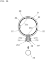
- FIG. 2A is a top view of the strainer 20 according to the first embodiment
- FIG. 2B is a front view of the strainer 20 according to the first embodiment.
- the strainer 20 is placed on and fixed to a bottom portion of the body 3, and is composed of a case 21 having a bottomed cylindrical shape made of synthetic resin, and a mesh filter 22 having a cylindrical shape that is integrated by insert molding or the like to the case 21.
- the mesh filter 22 is formed, for example, of a wire netting or a mesh member made of synthetic resin.
- the case 21 includes an upper cylindrical portion 21a having a cylindrical shape into which a lower end portion of the outer pipe 7 is inserted and fixed, a bottom plate portion 21b having a round shape, and four columnar portions 21c that are erected at even intervals in a circumferential direction on an outer circumference of the bottom plate portion 21b and that are connected to the upper cylindrical portion 21a.
- Four window portions 21d each having a rectangular shape are disposed between the four columnar portions 21c, and the mesh filter 22 is disposed in a stretched manner to each window portion 21d.
- the method for disposing the mesh filter 22 on the case 21 is not limited to the above-described method.
- One pair of retaining plate portions 21e and 21f are connected consecutively in a manner laid between an outer circumference of the upper cylindrical portion 21a and an outer circumference of the bottom plate portion 21b at both sides in a circumferential direction sandwiching one columnar portion 21.
- the retaining plate portions 21e and 21f include parallel plate portions 21g and 21h that extend in parallel outward from the case 21, and tip portions 21i and 21j that are disposed so as to be separated from each other from end portions of the parallel plate portions 21g and 21h. Further, retaining openings 21k and 21m that constitute a wafer retaining portion are formed across the parallel plate portions 21g and 21h and the tip portions 21i and 21j.
- a wafer 23 is a disk-shaped member formed of felt, and it is impregnated in advance with a fluorescent agent.
- a fluorescent agent for example, an agent that emits light when irradiated with ultraviolet may be used, but is not limited thereto.
- the height of the retaining openings 21k and 21m in the up-down direction is approximately equal to a thickness of the wafer 23. Further, the distance between the parallel plate portions 21g and 21h is smaller than an outer diameter of the wafer 23.
- the wafer 23 is placed to be opposed to the retaining plate portions 21e and 21f with respect to the case 21, as illustrated by the dotted line of FIG. 2A .
- the tip portions 21i and 21j come into contact with the wafer 23, and when the wafer is pushed further, the parallel plate portions 21g and 21h are elastically deformed so as to move away from each other.
- the parallel plate portions 21g and 21h return from the elastically deformed state.
- the side of the wafer 23 distant from the strainer 20 is retained by outer ends of the retaining openings 21k and 21m, such that the wafer 23 is suppressed from falling therefrom.
- the attachment of the wafer 23 may be performed simply by pushing the wafer 23 toward the strainer 20 without using a special jig, such that the assembling may be performed easily and the number of manufacturing steps may be reduced.
- the strainer 20 having the wafer 23 assembled thereto has the lower end of the outer pipe 7 inserted to the upper cylindrical portion 21a, and it is assembled to the accumulator 1 together with the outer pipe 7.
- the accumulator 1 configured as above will be described with reference to FIG. 1 .
- a configuration is illustrated as an example where the accumulator 1 is disposed between an evaporator and a compressor of the refrigeration cycle and where a gas refrigerant is generated by removing moisture contained in the refrigerant flowing in from the evaporator, and the gas is then returned to the compressor.
- the refrigerant In a state where the refrigerant is discharged from the evaporator, the refrigerant is conveyed to the accumulator 1 through a connecting piping (not shown).
- the refrigerant having reached the accumulator 1 is flown to the inner side of the body 3 through the refrigerant inlet port 8, collided against the gas-liquid separation member 16, and separated into a high-density liquid phase refrigerant including oil and a low-density gas phase refrigerant (gas refrigerant).
- liquid phase refrigerant and oil after being subjected to gas-liquid separation is pooled within the body 3 by its own weight.
- the separation of the liquid phase refrigerant and oil advances, and oil is pooled in the lower part the liquid phase refrigerant.
- liquid surface of the liquid phase refrigerant reaches a height position where a portion of the bag 11 accommodating the desiccant is immersed. Therefore, both the moisture contained in the liquid phase refrigerant and the hygroscopic moisture contained in the gas phase refrigerant are absorbed by the desiccant DA.
- the wafer 23 retained by the strainer 20 positioned at a bottom portion of the body 3 is also immersed in the liquid-phase refrigerant, such that the fluorescent agent impregnated in the wafer 23 is eluted into the liquid-phase refrigerant and is circulated within the piping. Therefore, when refrigerant leak occurs, the fluorescent agent is also simultaneously leaked out, such that the leakage area may be specified easily.
- the wafer 23 is retained by the retaining plate portions 21e and 21f, such that the area in which the wafer 23 is exposed is large, and the impregnated fluorescent agent may be eluted efficiently into the liquid-phase refrigerant.
- the gas phase refrigerant having been subjected to gas-liquid separation flows in through the opening portion on the upper end of the outer pipe 7 and descends within the outer pipe 7. Thereafter, the gas phase refrigerant turns back at the bottom portion of the outer pipe 7 and flows into the inner pipe 6, ascends within the inner pipe 6 and is guided to the refrigerant outlet port 9.
- the oil pooled together with the liquid-phase refrigerant at the lower portion of the body 3 moves toward the bottom portion side of the body 3 due, for example, to the specific gravity with respect to the liquid-phase refrigerant or the difference of properties, sucked into the gas phase refrigerant sucked toward the suction side of the compressor, and passes through the mesh filter 22 of the strainer 20, an oil return port 7e, and the inner space of the inner pipe 6 to return together with the gas phase refrigerant to the suction side of the compressor, thereby being circulated.
- foreign matters such as sludges are captured, by which the foreign matters are removed from the circulated refrigerant (including oil).
- the retaining plate portions 21e and 21f and the wafer 23 are arranged at a position being opposed to the columnar portions 21c, in other words, they do not block the window portions 21d, such that the oil passing through the window portions 21d is not disturbed thereby. Even if the wafer 23 falls off from the retaining plate portions 21e and 21f, the wafer 23 cannot pass through the mesh filter 22 and stays on the outer side of the strainer 20, such that it is prevented from being sucked into the piping of the refrigeration cycle as foreign matter.
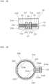
- FIG. 3A is a top view of a strainer 20A according to a second embodiment
- FIG. 3B is a side view of the strainer 20A according to the second embodiment.
- the strainer 20A may be assembled to the accumulator 1 illustrated in FIG. 1 .
- a case 21A and a mesh filter 22A have similar configurations as the case 21 and the mesh filter 22 according to the above-mentioned embodiment, such that detailed descriptions thereof are omitted.
- the wafer 23 is the same as that of the first embodiment.
- a retaining plate portion 21Ae is connected consecutively to an outer circumference of a bottom plate portion 21Ab disposed below one columnar portion 21Ac.
- the retaining plate portion 21Ae is disposed to extend outward in a radial direction of the case 21A. It is preferable for the bottom plate portion 21Ab and a lower surface of the retaining plate portion 21Ae to be positioned within a same plane.
- a perpendicular plate portion 21Af that extends in parallel with an outer circumference surface of the case 21A and toward an upper direction is connected consecutively to an outer end of the retaining plate portion 21Ae, and an inclined plate portion 21Ag that is inclined in a direction separating from the case 21A as it extends upward is connected consecutively to a top end of the perpendicular plate portion 21Af. Further, a retaining opening 21Ah that constitutes a wafer retaining portion is formed across the inclined plate portion 21Ag and the perpendicular plate portion 21Af.
- a width of the retaining opening 21Ah is approximately equal to a thickness of the wafer 23. Further, a distance between an outer circumference surface of the case 21A and the perpendicular plate portion 21Af is smaller than an outer diameter of the wafer 23.
- the wafer 23 is placed above the retaining plate portion 21Ae, as illustrated by the dotted line of FIG. 3B .
- the inclined plate portion 21Ag comes into contact with the wafer 23, and when the wafer is pushed further, the perpendicular plate portion 21Af is elastically deformed so as to move away from the outer circumference surface of the case 21A.
- the perpendicular plate portion 21Af returns from the elastically deformed state.
- the side of the wafer 23 distant from the retaining plate portion 21Ae is retained by outer ends of the retaining opening 21Ah, such that the wafer 23 is suppressed from falling therefrom.
- a portion of the wafer 23 is positioned outside the perpendicular plate portion 21Af.
- the attachment of the wafer 23 may be performed simply by pushing the wafer 23 toward the strainer 20A without using a special jig and the like, such that the assembling may be performed easily and the number of manufacturing steps may be reduced.
- the strainer 20A having the wafer 23 assembled thereto has the lower end of the outer pipe 7 ( FIG. 1 ) inserted to an upper cylindrical portion 21Aa, and it is assembled to the accumulator 1 together with the outer pipe 7.
- FIG. 4A is a top view of a strainer 20B according to a third embodiment
- FIG. 4B is a front view of the strainer 20B according to the third embodiment.
- the strainer 20B may be assembled to the accumulator 1 illustrated in FIG. 1 .
- a case 21B and a mesh filter 22B have similar configurations as the case 21 and the mesh filter 22 according to the above-mentioned embodiment, such that detailed descriptions thereof are omitted.
- the wafer 23 is the same as that of the first embodiment.
- One pair of lower retaining beam portions 21Be and 21Bf are disposed in a manner sandwiching one columnar portion 21Bc on an outer circumference of a bottom plate portion 21Bb and extending in parallel toward the outer direction, and an upper retaining beam portion 21Bg is disposed on an outer circumference of an upper cylindrical portion 21Ba above the same columnar portion 21Bc in a manner extending in parallel with the lower retaining beam portions 21Be and 21Bf.
- the lengths of the lower retaining beam portions 21Be and 21Bf and the upper retaining beam portion 21Bg are equal, and the distance between the lower retaining beam portions 21Be and 21Bf is set smaller than an outer diameter of the wafer 23.
- a retaining portion 21Bh having an inverted T shape is connected consecutively to outer ends of the lower retaining beam portions 21Be and 21Bf and the upper retaining beam portion 21Bg in a manner connecting the respective end portions.
- a pocket-like space surrounded by the lower retaining beam portions 21Be and 21Bf, the upper retaining beam portion 21Bg, and the retaining portion 21Bh constitutes a wafer retaining portion.
- the wafer 23 is placed below the upper retaining beam portion 21Bg, as illustrated by the dotted line of FIG. 4B .
- the wafer 23 enters the space surrounded by the lower retaining beam portions 21Be and 21Bf and the retaining portion 21Bh while being elastically deformed, and comes into contact with the upper retaining beam portion 21Bg and is locked in that manner.
- the wafer 23 returns from the elastically deformed state at a point of time when it passes the lower retaining beam portions 21Be and 21Bf, such that the falling of the wafer 23 may be suppressed.
- the attachment of the wafer 23 may be performed simply by pushing the wafer 23 toward the strainer 20B without using a special jig and the like, such that the assembling may be performed easily and the number of manufacturing steps may be reduced.
- the strainer 20B having the wafer 23 assembled thereto has the lower end of the outer pipe 7 ( FIG. 1 ) inserted to the upper cylindrical portion 21Ba, and it is assembled to the accumulator 1 together with the outer pipe 7.
- the strainer 20B is assembled to the accumulator 1, the bottom portion of the body 3 is positioned below the lower retaining beam portions 21Be and 21Bf and the retaining portion 21Bh, such that the falling of the wafer 23 may be suppressed.
- FIG. 5A is a top view of a strainer 20C according to a fourth embodiment
- FIG. 5B is a side view of the strainer 20C according to the fourth embodiment.
- the strainer 20C may be assembled to the accumulator 1 illustrated in FIG. 1 .
- a case 21C and a mesh filter 22C have similar configurations as the case 21 and the mesh filter 22 according to the above-mentioned embodiment, such that detailed descriptions thereof are omitted.
- the wafer 23 is the same as that of the first embodiment.
- a retaining plate portion 21Ce is connected consecutively to an outer circumference of an upper cylindrical portion 21Ca above one columnar portion 21Cc.
- the retaining plate portion 21Ce is disposed to extend toward an outer side in a radial direction of the case 21C.
- a perpendicular plate portion 21Cf that extends in parallel with an outer circumference surface of the case 21C and toward a lower direction is connected consecutively to an outer end of the retaining plate portion 21Ce, and an inclined plate portion 21Cg that is inclined in a direction separating from the case 21C as it extends downward is connected consecutively to a lower end of the perpendicular plate portion 21Cf. Further, a retaining opening 21Ch that constitutes a wafer retaining portion is formed across the inclined plate portion 21Cg and the perpendicular plate portion 21Cf.
- a width of the retaining opening 21Ch is approximately equal to a thickness of the wafer 23. Further, a distance between an outer circumference surface of the case 21C and the perpendicular plate portion 21Cf is smaller than an outer diameter of the wafer 23.
- a lower end of the inclined plate portion 21Cg is preferably at approximately a same height as a lower surface of a bottom plate portion 21Cb.
- the wafer 23 is placed below the retaining plate portion 21Ce, as illustrated by the dotted line of FIG. 5B .
- the inclined plate portion 21Cg comes into contact with the wafer 23, and when the wafer is pushed further, the perpendicular plate portion 21Cf is elastically deformed so as to move away from the outer circumference surface of the case 21C.
- the perpendicular plate portion 21Cf returns from the elastically deformed state.
- the side of the wafer 23 distant from the retaining plate portion 21Ce is retained by an outer end of the retaining opening 21Ch, such that the wafer 23 is suppressed from falling therefrom.
- a portion of the wafer 23 is positioned outside the perpendicular plate portion 21Cf.
- the attachment of the wafer 23 may be performed simply by pushing the wafer 23 toward the strainer 20C without using a special jig and the like, such that the assembling may be performed easily and the number of manufacturing steps may be reduced.
- the strainer 20C having the wafer 23 assembled thereto has the lower end of the outer pipe 7 ( FIG. 1 ) inserted to the upper cylindrical portion 21Ca, and it is assembled to the accumulator 1 together with the outer pipe 7.
- FIG. 6A is a top view of a strainer 20D according to a fifth embodiment
- FIG. 6B is a side view of the strainer 20D according to the fifth embodiment.
- the strainer 20D may be assembled to the accumulator 1 illustrated in FIG. 1 .
- a case 21D and a mesh filter 22D have similar configurations as the case 21 and the mesh filter 22 according to the above-mentioned embodiment, such that detailed descriptions thereof are omitted.
- the wafer 23 is the same as that of the first embodiment.
- An end portion of an arc-shaped retaining plate portion 21De is connected consecutively to an outer circumference of a bottom plate portion 21Db below one columnar portion 21Dc.
- the retaining plate portion 21De is disposed to extend upward in an arc.
- An inclined plate portion 21Dg that is inclined so as to separate from the case 21D as it extends upward is connected consecutively to a top end of the retaining plate portion 21De. Further, one pair of hook portions 21Dh and 21Di disposed to extend upward is connected consecutively to both sides in the width direction of the retaining plate portion 21De at a vicinity of the case 21D.
- the retaining plate portion 21De and the hook portions 21Dh and 21Di constitute a wafer retaining portion.
- An inscribed circle diameter of the retaining plate portion 21De is smaller than an outer diameter of the wafer 23.
- a width of the retaining plate portion 21De is approximately equal to a thickness of the wafer 23.
- a length of the hook portions 21Dh and 21Di is preferably equal to a radius of the wafer 23.
- the wafer 23 is placed above the retaining plate portion 21De, as illustrated by the dotted line of FIG. 6B .
- the inclined plate portion 21Dg comes into contact with the wafer 23, and when the wafer is pushed further, the retaining plate portion 21De is elastically deformed in a diameter-expanding manner, such that the wafer 23 may be accommodated between the hook portions 21Dh and 21Di.
- the elastic deformation of the retaining plate portion 21De is maintained in a state where the outer circumference surface of the wafer 23 is in contact with the inner surface of the retaining plate portion 21De and the outer circumference surface of the columnar portion 21Dc.
- the outer circumference surface of the wafer 23 is urged toward and retained by the columnar portion 21Dc, and both sides of the wafer 23 are retained by the hook portions 21Dh and 21Di, such that the wafer may be suppressed from falling therefrom.
- the attachment of the wafer 23 may be performed simply by pushing the wafer 23 toward the strainer 20D without using a special jig and the like, such that the assembling may be performed easily and the number of manufacturing steps may be reduced.
- the strainer 20D having the wafer 23 assembled thereto has the lower end of the outer pipe 7 ( FIG. 1 ) inserted to an upper cylindrical portion 21Da, and it is assembled to the accumulator 1 together with the outer pipe 7.
- FIG. 7A is a top view of a strainer 20E according to a sixth embodiment
- FIG. 7B is a side view of the strainer 20E according to the sixth embodiment.
- the strainer 20E may be assembled to the accumulator 1 illustrated in FIG. 1 .
- a case 21E and a mesh filter 22E have similar configurations as the case 21 and the mesh filter 22 according to the above-mentioned embodiment, such that detailed descriptions thereof are omitted.
- the wafer 23 is the same as that of the first embodiment.
- An end portion of an arc-shaped retaining plate portion 21Ee is connected consecutively to an outer circumference of an upper cylindrical portion 21Ea above one columnar portion 21Ec.
- the retaining plate portion 21Ee is disposed to extend downward in an arc.
- An inclined plate portion 21Eg that is inclined so as to separate from the case 21E as it extends downward is connected consecutively to a bottom end of the retaining plate portion 21Ee. Further, one pair of hook portions 21Eh and 21Ei that is disposed to extend downward is connected consecutively to both sides in the width direction of the retaining plate portion 21Ee at a vicinity of the case 21E.
- the retaining plate portion 21Ee and the hook portions 21Eh and 21Ei constitute a wafer retaining portion.
- An inscribed circle diameter of the retaining plate portion 21Ee is smaller than an outer diameter of the wafer 23.
- a width of the retaining plate portion 21Ee is approximately equal to a thickness of the wafer 23.
- a length of the hook portions 21Eh and 21Ei is preferably equal to a radius of the wafer 23.
- the wafer 23 is placed below the retaining plate portion 21Ee, as illustrated by the dotted line of FIG. 7B .
- the inclined plate portion 21Eg comes into contact with the wafer 23, and when the wafer is pushed further, the retaining plate portion 21Ee elastically deforms in a diameter-expanding manner, such that the wafer 23 may be accommodated between the hook portions 21Eh and 21Ei.
- the elastic deformation of the retaining plate portion 21Ee is maintained in a state where the outer circumference surface of the wafer 23 is in contact with the inner surface of the retaining plate portion 21Ee and the outer surface of the columnar portion 21Ec.
- the outer circumference surface of the wafer 23 is urged toward and retained by the columnar portion 21Ec, and both sides of the wafer 23 are retained by the hook portions 21Eh and 21Ei, such that the wafer may be suppressed from falling therefrom.
- the attachment of the wafer 23 may be performed simply by pushing the wafer 23 toward the strainer 20E without using a special jig and the like, such that the assembling may be performed easily and the number of manufacturing steps may be reduced.
- the strainer 20E having the wafer 23 assembled thereto has the lower end of the outer pipe 7 ( FIG. 1 ) inserted to the upper cylindrical portion 21Ea, and it is assembled to the accumulator 1 together with the outer pipe 7.
Landscapes
- Engineering & Computer Science (AREA)
- Mechanical Engineering (AREA)
- General Engineering & Computer Science (AREA)
- Chemical & Material Sciences (AREA)
- Physics & Mathematics (AREA)
- Thermal Sciences (AREA)
- Analytical Chemistry (AREA)
- Power Engineering (AREA)
- Combustion & Propulsion (AREA)
- Container, Conveyance, Adherence, Positioning, Of Wafer (AREA)
- Filtering Of Dispersed Particles In Gases (AREA)
Abstract
Description
- The present invention relates to an accumulator.
- Receiver tanks, accumulators and the like are used to store a refrigerant, which is circulated within a refrigeration cycle, in a gas-liquid separated manner. One type of such accumulators is equipped with a tank for separating the refrigerant flown therein into a gas phase refrigerant and a liquid phase refrigerant and storing the liquid phase refrigerant therein, wherein a desiccant is accommodated in the tank to remove moisture from the refrigerant.
- If refrigerant is leaked from a piping of the refrigeration cycle, it is necessary to find the leak at an early stage and take measures to stop the leakage, but there is a problem that even if refrigerant is leaked from the piping to the exterior, it may not be visually confirmed by the naked eye. Therefore, as illustrated in
Patent Literature 1, there has been developed a technique that mixes a fluorescent agent, that emits light when ultraviolet ray is irradiated thereto, into a refrigerant passing through a piping, and when the fluorescent agent is visually confirmed from the exterior, specifies the visually confirmed area as a refrigerant leakage area, and takes measures to stop the leakage and the like. - [PTL 1]
Japanese Patent Laid-Open Publication No. 2012-202640 - As a means for mixing such a fluorescent agent in the refrigerant, it may be possible to easily conduct elution of the fluorescent agent to the refrigerant by disposing a wafer impregnated with fluorescent agent in advance in an accumulator at an area where the refrigerant flowing into the accumulator contacts. However, if the wafer itself flows out to the exterior of the accumulator, problems such as the wafer flowing through the piping of the refrigeration cycle as foreign matter and clogging the various devices may occur. Therefore, it is necessary to devise a configuration to prevent the wafer from flowing out to the exterior of the accumulator.
- Meanwhile, it is possible to enclose a fluorescent agent together with a desiccant in a bag accommodating the desiccant disposed in the accumulator. However, the bag accommodating the desiccant is often arranged on an upper portion in the inner side of the accumulator to absorb moisture of the gas refrigerant, and in that case, there is a drawback that the fluorescent agent will be soaked in a liquid-phase refrigerant within the accumulator only when a liquid surface of the liquid-phase refrigerant therein is high, such that elution of the fluorescent agent may not be performed efficiently.
- Therefore, the present invention aims at providing an accumulator capable of preventing the fluorescent source from flowing out to the exterior even while enabling to effectively conduct elution of a fluorescent agent.
- In order to achieve the above-mentioned object, the accumulator according to the present invention characterizes in including
- a body,
- a pipe disposed on an inner side of the body, and
- a strainer attached to a lower end of the pipe,
- wherein a wafer retaining portion configured to retain a wafer impregnated with a fluorescent agent is formed on an outer circumference of the strainer.
- The present invention enables to provide an accumulator capable of preventing a fluorescent source from flowing out to the exterior even while enabling to effectively conduct elution of a fluorescent agent.
-
- [
FIG. 1] FIG. 1 is a vertical cross-sectional view of an accumulator according to a first embodiment. - [
FIG. 2A] FIG. 2A is a top view of a strainer according to the first embodiment. - [
FIG. 2B] FIG. 2B is a front view of the strainer according to the first embodiment. - [
FIG. 3A] FIG. 3A is a top view of a strainer according to a second embodiment. - [
FIG. 3B] FIG. 3B is a side view of the strainer according to the second embodiment. - [
FIG. 4A] FIG. 4A is a top view of a strainer according to a third embodiment. - [
FIG. 4B] FIG. 4B is a front view of the strainer according to the third embodiment. - [
FIG. 5A] FIG. 5A is a top view of a strainer according to a fourth embodiment. - [
FIG. 5B] FIG. 5B is a side view of the strainer according to the fourth embodiment. - [
FIG. 6A] FIG. 6A is a top view of a strainer according to a fifth embodiment. - [
FIG. 6B] FIG. 6B is a side view of the strainer according to the fifth embodiment. - [
FIG. 7A] FIG. 7A is a top view of a strainer according to a sixth embodiment. - [
FIG. 7B] FIG. 7B is a side view of the strainer according to the sixth embodiment. - An
accumulator 1 according to an embodiment of the present invention will be described below with reference to the drawings. -
FIG. 1 is a vertical cross-sectional view of theaccumulator 1 according to a first embodiment. Theaccumulator 1 includes a tankmain body 2, adouble pipe 5 disposed within the tankmain body 2, abag 11 accommodating a desiccant (moisture absorbent) DA, and astrainer 20. - The tank
main body 2 is composed of a body 3 having a bottomed cylindrical shape with a top end opened, and aheader 4 joined by girth welding to the body 3 via aweld portion 10 to seal an opening end of the body 3. The body 3 and theheader 4 are both formed of a metal such as an aluminum alloy. In the present specification, the side having theheader 4 is referred to as an upper part, and a bottom side of the body 3 with respect to theheader 4 is referred to as a lower part. - The
header 4 formed in an approximately disk-like shape has arefrigerant inlet port 8 and arefrigerant outlet port 9 that are formed to pass therethrough in a vertical direction. Aninner pipe 6 that extends to a vicinity of an inner bottom portion of the body 3 is connected to therefrigerant outlet port 9. Thedouble pipe 5 is formed by externally attaching an outer pipe (hereinafter also simply referred to as pipe) 7 to an outer side of theinner pipe 6. - Below the
header 4 is provided a gas-liquid separation member 16 having an inverted dish shape that separates a mixed refrigerant (refrigerant in which a gas phase refrigerant and a liquid phase refrigerant are mixed) flowing in through therefrigerant inlet port 8 into a liquid-phase refrigerant having a high density including compressor oil (hereinafter referred to as oil), and a gas phase refrigerant having a low density. - The
inner pipe 6 is formed of a metal such as an aluminum alloy, having a lower end portion thereof opened and an upper end portion thereof connected to therefrigerant outlet port 9 of theheader 4. Further, an outer circumference of theinner pipe 6 is inserted to an inner side of a plurality ofpipe ribs 7a disposed to protrude from an inner circumference surface of theouter pipe 7, by which theinner pipe 6 is retained stably within theouter pipe 7. - The
outer pipe 7 is formed of synthetic resin, and it is attached within the body 3 with the upper end portion opened. Astrainer 20 having a cylindrical shape is disposed on a bottom portion of theouter pipe 7. - A collar-shaped
portion 7b that extends outward in a radial direction and that includes a flow channel opening is connected to a center portion in a longitudinal direction of theouter pipe 7. Above the upper area of the collar-shapedportion 7b and on the outer circumference of theouter pipe 7 is disposed a retainingmember 7c that retains thebag 11 accommodating the desiccant DA, and the retainingmember 7c is attached to theouter pipe 7 using atying band 7d. -
FIG. 2A is a top view of thestrainer 20 according to the first embodiment, andFIG. 2B is a front view of thestrainer 20 according to the first embodiment. Thestrainer 20 is placed on and fixed to a bottom portion of the body 3, and is composed of acase 21 having a bottomed cylindrical shape made of synthetic resin, and amesh filter 22 having a cylindrical shape that is integrated by insert molding or the like to thecase 21. Themesh filter 22 is formed, for example, of a wire netting or a mesh member made of synthetic resin. - The
case 21 includes an uppercylindrical portion 21a having a cylindrical shape into which a lower end portion of theouter pipe 7 is inserted and fixed, abottom plate portion 21b having a round shape, and fourcolumnar portions 21c that are erected at even intervals in a circumferential direction on an outer circumference of thebottom plate portion 21b and that are connected to the uppercylindrical portion 21a. Fourwindow portions 21d each having a rectangular shape are disposed between the fourcolumnar portions 21c, and themesh filter 22 is disposed in a stretched manner to eachwindow portion 21d. The method for disposing themesh filter 22 on thecase 21 is not limited to the above-described method. - One pair of retaining
plate portions cylindrical portion 21a and an outer circumference of thebottom plate portion 21b at both sides in a circumferential direction sandwiching onecolumnar portion 21. The retainingplate portions parallel plate portions case 21, andtip portions parallel plate portions openings parallel plate portions tip portions - A
wafer 23 is a disk-shaped member formed of felt, and it is impregnated in advance with a fluorescent agent. As a fluorescent agent, for example, an agent that emits light when irradiated with ultraviolet may be used, but is not limited thereto. The height of the retainingopenings wafer 23. Further, the distance between theparallel plate portions wafer 23. - During assembly, the
wafer 23 is placed to be opposed to the retainingplate portions case 21, as illustrated by the dotted line ofFIG. 2A . By moving thewafer 23 toward thecase 21, at first, thetip portions wafer 23, and when the wafer is pushed further, theparallel plate portions wafer 23 fits to the retainingopenings parallel plate portions wafer 23 distant from thestrainer 20 is retained by outer ends of the retainingopenings wafer 23 is suppressed from falling therefrom. - According to the present embodiment, the attachment of the
wafer 23 may be performed simply by pushing thewafer 23 toward thestrainer 20 without using a special jig, such that the assembling may be performed easily and the number of manufacturing steps may be reduced. Thestrainer 20 having thewafer 23 assembled thereto has the lower end of theouter pipe 7 inserted to the uppercylindrical portion 21a, and it is assembled to theaccumulator 1 together with theouter pipe 7. - The operation of the
accumulator 1 configured as above will be described with reference toFIG. 1 . In the following description, a configuration is illustrated as an example where theaccumulator 1 is disposed between an evaporator and a compressor of the refrigeration cycle and where a gas refrigerant is generated by removing moisture contained in the refrigerant flowing in from the evaporator, and the gas is then returned to the compressor. - In a state where the refrigerant is discharged from the evaporator, the refrigerant is conveyed to the
accumulator 1 through a connecting piping (not shown). The refrigerant having reached theaccumulator 1 is flown to the inner side of the body 3 through therefrigerant inlet port 8, collided against the gas-liquid separation member 16, and separated into a high-density liquid phase refrigerant including oil and a low-density gas phase refrigerant (gas refrigerant). - The liquid phase refrigerant and oil after being subjected to gas-liquid separation is pooled within the body 3 by its own weight. In the process, the separation of the liquid phase refrigerant and oil advances, and oil is pooled in the lower part the liquid phase refrigerant. In this state, liquid surface of the liquid phase refrigerant reaches a height position where a portion of the
bag 11 accommodating the desiccant is immersed. Therefore, both the moisture contained in the liquid phase refrigerant and the hygroscopic moisture contained in the gas phase refrigerant are absorbed by the desiccant DA. - Further, the
wafer 23 retained by thestrainer 20 positioned at a bottom portion of the body 3 is also immersed in the liquid-phase refrigerant, such that the fluorescent agent impregnated in thewafer 23 is eluted into the liquid-phase refrigerant and is circulated within the piping. Therefore, when refrigerant leak occurs, the fluorescent agent is also simultaneously leaked out, such that the leakage area may be specified easily. According to the present embodiment, thewafer 23 is retained by the retainingplate portions wafer 23 is exposed is large, and the impregnated fluorescent agent may be eluted efficiently into the liquid-phase refrigerant. - Meanwhile, the gas phase refrigerant having been subjected to gas-liquid separation flows in through the opening portion on the upper end of the
outer pipe 7 and descends within theouter pipe 7. Thereafter, the gas phase refrigerant turns back at the bottom portion of theouter pipe 7 and flows into theinner pipe 6, ascends within theinner pipe 6 and is guided to therefrigerant outlet port 9. - The oil pooled together with the liquid-phase refrigerant at the lower portion of the body 3 moves toward the bottom portion side of the body 3 due, for example, to the specific gravity with respect to the liquid-phase refrigerant or the difference of properties, sucked into the gas phase refrigerant sucked toward the suction side of the compressor, and passes through the
mesh filter 22 of thestrainer 20, anoil return port 7e, and the inner space of theinner pipe 6 to return together with the gas phase refrigerant to the suction side of the compressor, thereby being circulated. When passing through themesh filter 22, foreign matters such as sludges are captured, by which the foreign matters are removed from the circulated refrigerant (including oil). - In this state, the retaining
plate portions wafer 23 are arranged at a position being opposed to thecolumnar portions 21c, in other words, they do not block thewindow portions 21d, such that the oil passing through thewindow portions 21d is not disturbed thereby. Even if thewafer 23 falls off from the retainingplate portions wafer 23 cannot pass through themesh filter 22 and stays on the outer side of thestrainer 20, such that it is prevented from being sucked into the piping of the refrigeration cycle as foreign matter. -
FIG. 3A is a top view of astrainer 20A according to a second embodiment, andFIG. 3B is a side view of thestrainer 20A according to the second embodiment. Thestrainer 20A may be assembled to theaccumulator 1 illustrated inFIG. 1 . Further, in thestrainer 20A, acase 21A and amesh filter 22A have similar configurations as thecase 21 and themesh filter 22 according to the above-mentioned embodiment, such that detailed descriptions thereof are omitted. Further, thewafer 23 is the same as that of the first embodiment. - A retaining plate portion 21Ae is connected consecutively to an outer circumference of a bottom plate portion 21Ab disposed below one columnar portion 21Ac. The retaining plate portion 21Ae is disposed to extend outward in a radial direction of the
case 21A. It is preferable for the bottom plate portion 21Ab and a lower surface of the retaining plate portion 21Ae to be positioned within a same plane. - A perpendicular plate portion 21Af that extends in parallel with an outer circumference surface of the
case 21A and toward an upper direction is connected consecutively to an outer end of the retaining plate portion 21Ae, and an inclined plate portion 21Ag that is inclined in a direction separating from thecase 21A as it extends upward is connected consecutively to a top end of the perpendicular plate portion 21Af. Further, a retaining opening 21Ah that constitutes a wafer retaining portion is formed across the inclined plate portion 21Ag and the perpendicular plate portion 21Af. - A width of the retaining opening 21Ah is approximately equal to a thickness of the
wafer 23. Further, a distance between an outer circumference surface of thecase 21A and the perpendicular plate portion 21Af is smaller than an outer diameter of thewafer 23. - During assembly, the
wafer 23 is placed above the retaining plate portion 21Ae, as illustrated by the dotted line ofFIG. 3B . By lowering thewafer 23 from this position, at first, the inclined plate portion 21Ag comes into contact with thewafer 23, and when the wafer is pushed further, the perpendicular plate portion 21Af is elastically deformed so as to move away from the outer circumference surface of thecase 21A. At a point of time when thewafer 23 fits to the retaining opening 21Ah and comes into contact with the retaining plate portion 21Ae, the perpendicular plate portion 21Af returns from the elastically deformed state. Thus, the side of thewafer 23 distant from the retaining plate portion 21Ae is retained by outer ends of the retaining opening 21Ah, such that thewafer 23 is suppressed from falling therefrom. A portion of thewafer 23 is positioned outside the perpendicular plate portion 21Af. - According to the present embodiment, the attachment of the
wafer 23 may be performed simply by pushing thewafer 23 toward thestrainer 20A without using a special jig and the like, such that the assembling may be performed easily and the number of manufacturing steps may be reduced. Thestrainer 20A having thewafer 23 assembled thereto has the lower end of the outer pipe 7 (FIG. 1 ) inserted to an upper cylindrical portion 21Aa, and it is assembled to theaccumulator 1 together with theouter pipe 7. -
FIG. 4A is a top view of astrainer 20B according to a third embodiment, andFIG. 4B is a front view of thestrainer 20B according to the third embodiment. Thestrainer 20B may be assembled to theaccumulator 1 illustrated inFIG. 1 . Further, in thestrainer 20B, acase 21B and amesh filter 22B have similar configurations as thecase 21 and themesh filter 22 according to the above-mentioned embodiment, such that detailed descriptions thereof are omitted. Further, thewafer 23 is the same as that of the first embodiment. - One pair of lower retaining beam portions 21Be and 21Bf are disposed in a manner sandwiching one columnar portion 21Bc on an outer circumference of a bottom plate portion 21Bb and extending in parallel toward the outer direction, and an upper retaining beam portion 21Bg is disposed on an outer circumference of an upper cylindrical portion 21Ba above the same columnar portion 21Bc in a manner extending in parallel with the lower retaining beam portions 21Be and 21Bf. The lengths of the lower retaining beam portions 21Be and 21Bf and the upper retaining beam portion 21Bg are equal, and the distance between the lower retaining beam portions 21Be and 21Bf is set smaller than an outer diameter of the
wafer 23. - A retaining portion 21Bh having an inverted T shape is connected consecutively to outer ends of the lower retaining beam portions 21Be and 21Bf and the upper retaining beam portion 21Bg in a manner connecting the respective end portions. A pocket-like space surrounded by the lower retaining beam portions 21Be and 21Bf, the upper retaining beam portion 21Bg, and the retaining portion 21Bh constitutes a wafer retaining portion.
- During assembly, the
wafer 23 is placed below the upper retaining beam portion 21Bg, as illustrated by the dotted line ofFIG. 4B . By lifting thewafer 23 from this position, thewafer 23 enters the space surrounded by the lower retaining beam portions 21Be and 21Bf and the retaining portion 21Bh while being elastically deformed, and comes into contact with the upper retaining beam portion 21Bg and is locked in that manner. Thewafer 23 returns from the elastically deformed state at a point of time when it passes the lower retaining beam portions 21Be and 21Bf, such that the falling of thewafer 23 may be suppressed. - According to the present embodiment, the attachment of the
wafer 23 may be performed simply by pushing thewafer 23 toward thestrainer 20B without using a special jig and the like, such that the assembling may be performed easily and the number of manufacturing steps may be reduced. Thestrainer 20B having thewafer 23 assembled thereto has the lower end of the outer pipe 7 (FIG. 1 ) inserted to the upper cylindrical portion 21Ba, and it is assembled to theaccumulator 1 together with theouter pipe 7. When thestrainer 20B is assembled to theaccumulator 1, the bottom portion of the body 3 is positioned below the lower retaining beam portions 21Be and 21Bf and the retaining portion 21Bh, such that the falling of thewafer 23 may be suppressed. -
FIG. 5A is a top view of astrainer 20C according to a fourth embodiment, andFIG. 5B is a side view of thestrainer 20C according to the fourth embodiment. Thestrainer 20C may be assembled to theaccumulator 1 illustrated inFIG. 1 . Further, in thestrainer 20C, acase 21C and amesh filter 22C have similar configurations as thecase 21 and themesh filter 22 according to the above-mentioned embodiment, such that detailed descriptions thereof are omitted. Further, thewafer 23 is the same as that of the first embodiment. - A retaining plate portion 21Ce is connected consecutively to an outer circumference of an upper cylindrical portion 21Ca above one columnar portion 21Cc. The retaining plate portion 21Ce is disposed to extend toward an outer side in a radial direction of the
case 21C. - A perpendicular plate portion 21Cf that extends in parallel with an outer circumference surface of the
case 21C and toward a lower direction is connected consecutively to an outer end of the retaining plate portion 21Ce, and an inclined plate portion 21Cg that is inclined in a direction separating from thecase 21C as it extends downward is connected consecutively to a lower end of the perpendicular plate portion 21Cf. Further, a retaining opening 21Ch that constitutes a wafer retaining portion is formed across the inclined plate portion 21Cg and the perpendicular plate portion 21Cf. - A width of the retaining opening 21Ch is approximately equal to a thickness of the
wafer 23. Further, a distance between an outer circumference surface of thecase 21C and the perpendicular plate portion 21Cf is smaller than an outer diameter of thewafer 23. A lower end of the inclined plate portion 21Cg is preferably at approximately a same height as a lower surface of a bottom plate portion 21Cb. - During assembly, the
wafer 23 is placed below the retaining plate portion 21Ce, as illustrated by the dotted line ofFIG. 5B . By lifting thewafer 23 from this position, at first, the inclined plate portion 21Cg comes into contact with thewafer 23, and when the wafer is pushed further, the perpendicular plate portion 21Cf is elastically deformed so as to move away from the outer circumference surface of thecase 21C. At a point of time when thewafer 23 fits to the retaining opening 21Ch and comes into contact with the retaining plate portion 21Ce, the perpendicular plate portion 21Cf returns from the elastically deformed state. Thus, the side of thewafer 23 distant from the retaining plate portion 21Ce is retained by an outer end of the retaining opening 21Ch, such that thewafer 23 is suppressed from falling therefrom. A portion of thewafer 23 is positioned outside the perpendicular plate portion 21Cf. - According to the present embodiment, the attachment of the
wafer 23 may be performed simply by pushing thewafer 23 toward thestrainer 20C without using a special jig and the like, such that the assembling may be performed easily and the number of manufacturing steps may be reduced. Thestrainer 20C having thewafer 23 assembled thereto has the lower end of the outer pipe 7 (FIG. 1 ) inserted to the upper cylindrical portion 21Ca, and it is assembled to theaccumulator 1 together with theouter pipe 7. -
FIG. 6A is a top view of astrainer 20D according to a fifth embodiment, andFIG. 6B is a side view of thestrainer 20D according to the fifth embodiment. Thestrainer 20D may be assembled to theaccumulator 1 illustrated inFIG. 1 . Further, in thestrainer 20D, acase 21D and amesh filter 22D have similar configurations as thecase 21 and themesh filter 22 according to the above-mentioned embodiment, such that detailed descriptions thereof are omitted. Further, thewafer 23 is the same as that of the first embodiment. - An end portion of an arc-shaped retaining plate portion 21De is connected consecutively to an outer circumference of a bottom plate portion 21Db below one columnar portion 21Dc. The retaining plate portion 21De is disposed to extend upward in an arc.
- An inclined plate portion 21Dg that is inclined so as to separate from the
case 21D as it extends upward is connected consecutively to a top end of the retaining plate portion 21De. Further, one pair of hook portions 21Dh and 21Di disposed to extend upward is connected consecutively to both sides in the width direction of the retaining plate portion 21De at a vicinity of thecase 21D. The retaining plate portion 21De and the hook portions 21Dh and 21Di constitute a wafer retaining portion. - An inscribed circle diameter of the retaining plate portion 21De is smaller than an outer diameter of the
wafer 23. A width of the retaining plate portion 21De is approximately equal to a thickness of thewafer 23. A length of the hook portions 21Dh and 21Di is preferably equal to a radius of thewafer 23. - During assembly, the
wafer 23 is placed above the retaining plate portion 21De, as illustrated by the dotted line ofFIG. 6B . By lowering thewafer 23 from this position, at first, the inclined plate portion 21Dg comes into contact with thewafer 23, and when the wafer is pushed further, the retaining plate portion 21De is elastically deformed in a diameter-expanding manner, such that thewafer 23 may be accommodated between the hook portions 21Dh and 21Di. The elastic deformation of the retaining plate portion 21De is maintained in a state where the outer circumference surface of thewafer 23 is in contact with the inner surface of the retaining plate portion 21De and the outer circumference surface of the columnar portion 21Dc. By the above-mentioned elastic force, the outer circumference surface of thewafer 23 is urged toward and retained by the columnar portion 21Dc, and both sides of thewafer 23 are retained by the hook portions 21Dh and 21Di, such that the wafer may be suppressed from falling therefrom. - According to the present embodiment, the attachment of the
wafer 23 may be performed simply by pushing thewafer 23 toward thestrainer 20D without using a special jig and the like, such that the assembling may be performed easily and the number of manufacturing steps may be reduced. Thestrainer 20D having thewafer 23 assembled thereto has the lower end of the outer pipe 7 (FIG. 1 ) inserted to an upper cylindrical portion 21Da, and it is assembled to theaccumulator 1 together with theouter pipe 7. -
FIG. 7A is a top view of astrainer 20E according to a sixth embodiment, andFIG. 7B is a side view of thestrainer 20E according to the sixth embodiment. Thestrainer 20E may be assembled to theaccumulator 1 illustrated inFIG. 1 . Further, in thestrainer 20E, acase 21E and amesh filter 22E have similar configurations as thecase 21 and themesh filter 22 according to the above-mentioned embodiment, such that detailed descriptions thereof are omitted. Further, thewafer 23 is the same as that of the first embodiment. - An end portion of an arc-shaped retaining plate portion 21Ee is connected consecutively to an outer circumference of an upper cylindrical portion 21Ea above one columnar portion 21Ec. The retaining plate portion 21Ee is disposed to extend downward in an arc.
- An inclined plate portion 21Eg that is inclined so as to separate from the
case 21E as it extends downward is connected consecutively to a bottom end of the retaining plate portion 21Ee. Further, one pair of hook portions 21Eh and 21Ei that is disposed to extend downward is connected consecutively to both sides in the width direction of the retaining plate portion 21Ee at a vicinity of thecase 21E. The retaining plate portion 21Ee and the hook portions 21Eh and 21Ei constitute a wafer retaining portion. - An inscribed circle diameter of the retaining plate portion 21Ee is smaller than an outer diameter of the
wafer 23. A width of the retaining plate portion 21Ee is approximately equal to a thickness of thewafer 23. A length of the hook portions 21Eh and 21Ei is preferably equal to a radius of thewafer 23. - During assembly, the
wafer 23 is placed below the retaining plate portion 21Ee, as illustrated by the dotted line ofFIG. 7B . By lifting thewafer 23 from this position, at first, the inclined plate portion 21Eg comes into contact with thewafer 23, and when the wafer is pushed further, the retaining plate portion 21Ee elastically deforms in a diameter-expanding manner, such that thewafer 23 may be accommodated between the hook portions 21Eh and 21Ei. The elastic deformation of the retaining plate portion 21Ee is maintained in a state where the outer circumference surface of thewafer 23 is in contact with the inner surface of the retaining plate portion 21Ee and the outer surface of the columnar portion 21Ec. By the above-mentioned elastic force, the outer circumference surface of thewafer 23 is urged toward and retained by the columnar portion 21Ec, and both sides of thewafer 23 are retained by the hook portions 21Eh and 21Ei, such that the wafer may be suppressed from falling therefrom. - According to the present embodiment, the attachment of the
wafer 23 may be performed simply by pushing thewafer 23 toward thestrainer 20E without using a special jig and the like, such that the assembling may be performed easily and the number of manufacturing steps may be reduced. Thestrainer 20E having thewafer 23 assembled thereto has the lower end of the outer pipe 7 (FIG. 1 ) inserted to the upper cylindrical portion 21Ea, and it is assembled to theaccumulator 1 together with theouter pipe 7. - The present invention has been illustrated above with reference to the embodiments, but the present invention is not limited to the above-mentioned embodiments, and various modifications are enabled within the scope of the invention.
-
- 1 Accumulator
- 2 Tank main body
- 3 Body
- 4 Header
- 5 Double pipe
- 6 Inner pipe
- 7 Outer pipe
- 8 Refrigerant inlet port
- 9 Refrigerant outlet port
- 11 Bag
- 20, 20A, 20B, 20C, 20D, 20E Strainer
- 21, 21A, 21B, 21C, 21D, 21E Case
- 22, 22A, 22B, 22C, 22D, 22E Mesh filter
- 23 Wafer
Claims (8)
- An accumulator comprising:a body;a pipe disposed on an inner side of the body; anda strainer attached to a lower end of the pipe,wherein a wafer retaining portion configured to retain a wafer impregnated with a fluorescent agent is formed on an outer circumference of the strainer.
- The accumulator according to claim 1,wherein the strainer includes:a case including an upper cylindrical portion configured to fit to the pipe, a bottom plate portion, and a plurality of columnar portions configured to connect the upper cylindrical portion and the bottom plate portion; anda mesh filter formed between the columnar portions, andwherein the wafer retaining portion is disposed at a position opposed to the columnar portion.
- The accumulator according to claim 2,
further comprising a pair of retaining plates disposed to extend from the case sandwiching the columnar portion, and a retaining opening formed on the retaining plate, wherein the wafer is retained in the retaining opening. - The accumulator according to claim 2,
further comprising a retaining plate disposed to extend from the bottom plate portion below the columnar portion, a perpendicular plate disposed to extend along an outer circumference surface of the case from the retaining plate, and a retaining opening formed on the perpendicular plate, wherein the wafer is retained in the retaining opening. - The accumulator according to claim 2,
further comprising a retaining plate disposed to extend from the upper cylindrical portion above the columnar portion, a perpendicular plate disposed to extend along an outer circumference surface of the case from the retaining plate, and a retaining opening formed on the perpendicular plate, wherein the wafer is retained in the retaining opening. - The accumulator according to claim 2,further comprising an upper retaining beam portion disposed to extend from the upper cylindrical portion above the columnar portion, a pair of lower retaining beam portions disposed to extend from the bottom plate portion in a manner sandwiching the columnar portion, and a retaining portion connected consecutively to end portions of the upper retaining beam portion and the lower retaining beam portion, andwherein the wafer is retained between the upper retaining beam portion, the lower retaining beam portion, and the retaining portion.
- The accumulator according to claim 2,further comprising a retaining plate disposed to extend in an arc shape from the bottom plate portion below the columnar portion, and a pair of hook portions disposed to extend from both sides in a width direction of the retaining plate, andwherein the wafer is retained between the retaining plate and the hook portions.
- The accumulator according to claim 2,further comprising a retaining plate disposed to extend in an arc shape from the upper cylindrical portion above the columnar portion, and a pair of hook portions disposed to extend from both sides in a width direction of the retaining plate, andwherein the wafer is retained between the retaining plate and the hook portion.
Applications Claiming Priority (2)
| Application Number | Priority Date | Filing Date | Title |
|---|---|---|---|
| JP2021130666A JP7475060B2 (en) | 2021-08-10 | 2021-08-10 | accumulator |
| PCT/JP2022/029987 WO2023017782A1 (en) | 2021-08-10 | 2022-08-04 | Accumulator |
Publications (2)
| Publication Number | Publication Date |
|---|---|
| EP4386282A1 true EP4386282A1 (en) | 2024-06-19 |
| EP4386282A4 EP4386282A4 (en) | 2025-07-16 |
Family
ID=85199956
Family Applications (1)
| Application Number | Title | Priority Date | Filing Date |
|---|---|---|---|
| EP22855844.1A Pending EP4386282A4 (en) | 2021-08-10 | 2022-08-04 | ACCUMULATOR |
Country Status (4)
| Country | Link |
|---|---|
| EP (1) | EP4386282A4 (en) |
| JP (1) | JP7475060B2 (en) |
| CN (1) | CN117813471A (en) |
| WO (1) | WO2023017782A1 (en) |
Families Citing this family (1)
| Publication number | Priority date | Publication date | Assignee | Title |
|---|---|---|---|---|
| WO2025004228A1 (en) * | 2023-06-28 | 2025-01-02 | 三菱電機株式会社 | Refrigeration device and air conditioning device |
Family Cites Families (9)
| Publication number | Priority date | Publication date | Assignee | Title |
|---|---|---|---|---|
| JP4257027B2 (en) * | 2000-10-26 | 2009-04-22 | カルソニックカンセイ株式会社 | Liquid tank |
| JP5379977B2 (en) * | 2008-01-09 | 2013-12-25 | 株式会社不二工機 | Liquid tank |
| JP2010121910A (en) | 2008-11-21 | 2010-06-03 | Calsonic Kansei Corp | Pressure container |
| JP5715864B2 (en) | 2011-03-28 | 2015-05-13 | 株式会社不二工機 | Receiver dryer |
| JP6055291B2 (en) | 2012-11-27 | 2016-12-27 | 株式会社不二工機 | accumulator |
| JP6434276B2 (en) * | 2014-10-31 | 2018-12-05 | 株式会社不二工機 | Receiver dryer |
| JP6661345B2 (en) * | 2015-07-14 | 2020-03-11 | 株式会社不二工機 | accumulator |
| US10247455B2 (en) * | 2016-07-13 | 2019-04-02 | Hanon Systems | Condenser receiver drier refrigerant filter |
| JP6600654B2 (en) * | 2016-10-25 | 2019-10-30 | 株式会社不二工機 | accumulator |
-
2021
- 2021-08-10 JP JP2021130666A patent/JP7475060B2/en active Active
-
2022
- 2022-08-04 EP EP22855844.1A patent/EP4386282A4/en active Pending
- 2022-08-04 CN CN202280055601.5A patent/CN117813471A/en active Pending
- 2022-08-04 WO PCT/JP2022/029987 patent/WO2023017782A1/en not_active Ceased
Also Published As
| Publication number | Publication date |
|---|---|
| EP4386282A4 (en) | 2025-07-16 |
| JP2023025425A (en) | 2023-02-22 |
| JP7475060B2 (en) | 2024-04-26 |
| CN117813471A (en) | 2024-04-02 |
| WO2023017782A1 (en) | 2023-02-16 |
Similar Documents
| Publication | Publication Date | Title |
|---|---|---|
| US4827725A (en) | Suction accumulator with dirt trap | |
| CA2168084C (en) | Refrigerant circuit accumulator and associated fabrication methods | |
| CN103968624B (en) | A kind of liquid reservoir and liquid reservoir manufacture method | |
| KR101386321B1 (en) | Liquid tank | |
| JP2012026660A (en) | Refrigerant tank | |
| US6389843B2 (en) | Receiver dryer with bottom inlet | |
| EP3534092A1 (en) | Accumulator | |
| US12263420B2 (en) | Filter cartridge | |
| JP7475060B2 (en) | accumulator | |
| CN106352620B (en) | Liquid storage device | |
| EP3671074B1 (en) | Accumulator | |
| EP3677857A1 (en) | Accumulator | |
| JP6594685B2 (en) | accumulator | |
| US10821811B2 (en) | Refrigerant container | |
| US20060196219A1 (en) | Accumulator with full-flow filtering | |
| US4633679A (en) | Accumulator-dehydrator assembly for an air conditioning system | |
| EP3293471B1 (en) | Accumulator | |
| EP4394283A1 (en) | Accumulator | |
| KR0183418B1 (en) | Drying device used for air conditioner of vehicle | |
| US6959563B2 (en) | Insert for use in a refrigerant receiver | |
| CN112013580A (en) | Liquid storage device and assembling method thereof | |
| WO2008084384A2 (en) | Accumulator for automotive refrigeration system | |
| EP4394282A1 (en) | Accumulator | |
| CN122041443A (en) | Box (BW) | |
| CN216745047U (en) | Fixed plate and liquid storage device with same |
Legal Events
| Date | Code | Title | Description |
|---|---|---|---|
| STAA | Information on the status of an ep patent application or granted ep patent |
Free format text: STATUS: THE INTERNATIONAL PUBLICATION HAS BEEN MADE |
|
| PUAI | Public reference made under article 153(3) epc to a published international application that has entered the european phase |
Free format text: ORIGINAL CODE: 0009012 |
|
| STAA | Information on the status of an ep patent application or granted ep patent |
Free format text: STATUS: REQUEST FOR EXAMINATION WAS MADE |
|
| 17P | Request for examination filed |
Effective date: 20240201 |
|
| AK | Designated contracting states |
Kind code of ref document: A1 Designated state(s): AL AT BE BG CH CY CZ DE DK EE ES FI FR GB GR HR HU IE IS IT LI LT LU LV MC MK MT NL NO PL PT RO RS SE SI SK SM TR |
|
| DAV | Request for validation of the european patent (deleted) | ||
| DAX | Request for extension of the european patent (deleted) | ||
| A4 | Supplementary search report drawn up and despatched |
Effective date: 20250618 |
|
| RIC1 | Information provided on ipc code assigned before grant |
Ipc: F25B 43/00 20060101AFI20250612BHEP Ipc: F25B 49/00 20060101ALI20250612BHEP |