EP4386258A1 - Lamp mounting structure and lamp - Google Patents
Lamp mounting structure and lamp Download PDFInfo
- Publication number
- EP4386258A1 EP4386258A1 EP22855456.4A EP22855456A EP4386258A1 EP 4386258 A1 EP4386258 A1 EP 4386258A1 EP 22855456 A EP22855456 A EP 22855456A EP 4386258 A1 EP4386258 A1 EP 4386258A1
- Authority
- EP
- European Patent Office
- Prior art keywords
- assembly
- connection
- lamp
- lock catch
- mounting
- Prior art date
- Legal status (The legal status is an assumption and is not a legal conclusion. Google has not performed a legal analysis and makes no representation as to the accuracy of the status listed.)
- Pending
Links
- 230000005540 biological transmission Effects 0.000 claims description 22
- 238000000034 method Methods 0.000 abstract description 8
- 238000009434 installation Methods 0.000 description 33
- 238000011900 installation process Methods 0.000 description 13
- 230000017105 transposition Effects 0.000 description 8
- 230000000694 effects Effects 0.000 description 7
- 229910000831 Steel Inorganic materials 0.000 description 5
- 239000010959 steel Substances 0.000 description 5
- 230000005484 gravity Effects 0.000 description 4
- 230000005489 elastic deformation Effects 0.000 description 3
- 230000009286 beneficial effect Effects 0.000 description 2
- 239000013013 elastic material Substances 0.000 description 2
- 230000033001 locomotion Effects 0.000 description 2
- 238000012423 maintenance Methods 0.000 description 2
- 238000003860 storage Methods 0.000 description 2
- 230000000007 visual effect Effects 0.000 description 2
- 238000004140 cleaning Methods 0.000 description 1
- 239000000463 material Substances 0.000 description 1
- 239000002184 metal Substances 0.000 description 1
- 238000003825 pressing Methods 0.000 description 1
- 238000000926 separation method Methods 0.000 description 1
- 238000003466 welding Methods 0.000 description 1
Images





Classifications
-
- F—MECHANICAL ENGINEERING; LIGHTING; HEATING; WEAPONS; BLASTING
- F21—LIGHTING
- F21V—FUNCTIONAL FEATURES OR DETAILS OF LIGHTING DEVICES OR SYSTEMS THEREOF; STRUCTURAL COMBINATIONS OF LIGHTING DEVICES WITH OTHER ARTICLES, NOT OTHERWISE PROVIDED FOR
- F21V21/00—Supporting, suspending, or attaching arrangements for lighting devices; Hand grips
- F21V21/14—Adjustable mountings
- F21V21/30—Pivoted housings or frames
-
- F—MECHANICAL ENGINEERING; LIGHTING; HEATING; WEAPONS; BLASTING
- F21—LIGHTING
- F21V—FUNCTIONAL FEATURES OR DETAILS OF LIGHTING DEVICES OR SYSTEMS THEREOF; STRUCTURAL COMBINATIONS OF LIGHTING DEVICES WITH OTHER ARTICLES, NOT OTHERWISE PROVIDED FOR
- F21V21/00—Supporting, suspending, or attaching arrangements for lighting devices; Hand grips
- F21V21/02—Wall, ceiling, or floor bases; Fixing pendants or arms to the bases
-
- F—MECHANICAL ENGINEERING; LIGHTING; HEATING; WEAPONS; BLASTING
- F21—LIGHTING
- F21V—FUNCTIONAL FEATURES OR DETAILS OF LIGHTING DEVICES OR SYSTEMS THEREOF; STRUCTURAL COMBINATIONS OF LIGHTING DEVICES WITH OTHER ARTICLES, NOT OTHERWISE PROVIDED FOR
- F21V21/00—Supporting, suspending, or attaching arrangements for lighting devices; Hand grips
- F21V21/14—Adjustable mountings
- F21V21/26—Pivoted arms
-
- F—MECHANICAL ENGINEERING; LIGHTING; HEATING; WEAPONS; BLASTING
- F21—LIGHTING
- F21V—FUNCTIONAL FEATURES OR DETAILS OF LIGHTING DEVICES OR SYSTEMS THEREOF; STRUCTURAL COMBINATIONS OF LIGHTING DEVICES WITH OTHER ARTICLES, NOT OTHERWISE PROVIDED FOR
- F21V21/00—Supporting, suspending, or attaching arrangements for lighting devices; Hand grips
- F21V21/36—Hoisting or lowering devices, e.g. for maintenance
-
- F—MECHANICAL ENGINEERING; LIGHTING; HEATING; WEAPONS; BLASTING
- F21—LIGHTING
- F21S—NON-PORTABLE LIGHTING DEVICES; SYSTEMS THEREOF; VEHICLE LIGHTING DEVICES SPECIALLY ADAPTED FOR VEHICLE EXTERIORS
- F21S8/00—Lighting devices intended for fixed installation
- F21S8/04—Lighting devices intended for fixed installation intended only for mounting on a ceiling or the like overhead structures
- F21S8/043—Lighting devices intended for fixed installation intended only for mounting on a ceiling or the like overhead structures mounted by means of a rigid support, e.g. bracket or arm
-
- F—MECHANICAL ENGINEERING; LIGHTING; HEATING; WEAPONS; BLASTING
- F21—LIGHTING
- F21V—FUNCTIONAL FEATURES OR DETAILS OF LIGHTING DEVICES OR SYSTEMS THEREOF; STRUCTURAL COMBINATIONS OF LIGHTING DEVICES WITH OTHER ARTICLES, NOT OTHERWISE PROVIDED FOR
- F21V21/00—Supporting, suspending, or attaching arrangements for lighting devices; Hand grips
- F21V21/02—Wall, ceiling, or floor bases; Fixing pendants or arms to the bases
- F21V21/03—Ceiling bases, e.g. ceiling roses
Definitions
- the present application relates to the technical field of lighting devices, and in particular, to a lamp mounting structure and a lamp.
- Ceiling lamps have become the most common ceiling lamp for indoor lighting due to their characteristics such as being closer to natural lighting. They are widely used in various occasions such as homes, offices, and entertainment venues.
- Existing ceiling lamps in the market usually include a bottom shell, a light source, and a lampshade.
- most of the existing ceiling lamps need to remove the lampshade or to remove both the lampshade and the light source, fix the chassis on the wall or ceiling, and then install wires of the light source, and finally mount the lampshade on the chassis.
- Due to the large area of the ceiling lamp the visual conditions are extremely poor, and it is operated at high altitudes, the installation process is complicated and requires the assistance of many people to complete the installation. The installation is difficult and expensive, and the installation efficiency is low.
- the later maintenance and cleaning process of the ceiling lamp due to the inconvenience of installation and disassembly, it also takes time and effort for the staff to disassemble and assemble.
- the object of the present application is to provide a lamp mounting structure that is time-saving, labor-saving, efficient, safe, has high visibility, meets high-altitude transposition requirements, and can be installed and disassembled by a single person.
- the present application provides a lamp mounting structure, for assembling a lamp on a mounting wall, including: a mounting assembly, a connection assembly, and a chassis assembly, the mounting assembly is fixedly installed on the mounting wall, the chassis assembly is fixedly connected to a lamp main body, the mounting assembly, the connection assembly, and the chassis assembly are rotatably connected end-to-end in sequence to form a Z-shaped structure, the mounting assembly is provided with a first lock catch part, and at least one second lock catch part is provided on the chassis assembly at a position corresponding to the first lock catch part, and the first lock catch part is connected to the second lock catch part in a lock catch manner.
- connection assembly includes a pair of connection rods arranged in parallel and a first connection part and a second connection part respectively located at both ends of the connection rods, and the mounting assembly is rotatably connected with the first connection part, and the chassis assembly is rotatably connected with the second connection part.
- the first connection part includes a first connection hole and a connection piece, and a side of the mounting assembly away from the mounting wall extends downward at a position corresponding to the first connection part to form a third connection part, and a second connection hole is provided in the third connection part at a position corresponding to the first connection hole, and the connection piece passes through the first connection hole and the second connection hole to rotatably connect the mounting assembly and the first connection part.
- the lamp mounting structure further includes a snap-fit assembly, the snap-fit assembly is fixedly connected to a side of the chassis assembly facing the connection assembly, and the second connection part is rotatably connected to the chassis assembly through the snap-fit assembly.
- the snap-fit assembly includes a first snap-fit member and a second snap-fit member
- the first snap-fit member includes a first fixing part
- the first fixing part is fixedly connected to the chassis assembly, one end of the first fixing part is bent upward and inward to form a bent part, a receiving groove is formed between the bent part and the first fixing part, and a rotating shaft of the second connection part passes through the receiving groove and is rotatably connected to the first snap-fit member.
- an end of the bent part extends towards a direction away from the first fixing part to form a guide part
- the second snap-fit member includes a second fixing part, the second fixing part is fixedly connected to the first fixing part, and an end of the second fixing part close to the bent part extends towards an interface part where the bent part and the guide part are connected to form a position limiting part, the position limiting part is in contact with the interface part for position limiting.
- the second lock catch part includes a self-locking structure
- the self-locking structure includes a slide rail, a sliding part, an elastic member, and a position limiting member
- the slide rail is fixedly installed on the chassis assembly and is slidably connected with the sliding part
- a position of the sliding part corresponding to the first lock catch part is provided with a buckle part that is connected with the first lock catch part in a lock catch manner
- a side of the sliding part away from the buckle part is provided with a through hole
- the position limiting member includes a position limiting shaft and a position limiting block vertically connected to the position limiting shaft, one end of the position limiting shaft away from the position limiting block passes through the through hole and is slidably connected to the sliding part
- the elastic member is sleeved on the position limiting shaft and is clamped between the sliding part and the position limiting block.
- the second lock catch part further includes a detachment assembly
- the detachment assembly includes a detachment button and a transmission part
- the transmission part is fixedly connected to the sliding part
- the disassembly button passes through the first fixing hole in a side wall of the chassis assembly and is fixedly connected to the transmission part to drive the sliding part to slide relative to the slide rail.
- the transmission part is fixedly connected to sliding parts of two self-locking structures to drive the two sliding parts to slide synchronously.
- Another object of the present application is to provide a lamp including the above lamp mounting structure.
- the present application provides a lamp, including a lamp main body and the above lamp mounting structure, the lamp main body is fixedly connected to a side of the chassis assembly away from the connection assembly.
- the beneficial effects of the present application are as follows.
- the present application by rotatably connecting the mounting assembly, the connection assembly, and the chassis assembly end-to-end in sequence to form a Z-shaped structure, solving the problems of poor viewing angle when aligning and installing the lamp, and realizing the transposition requirement for suspended operations, making the installation process of lamps time-saving, labor-saving, efficient, and safe, especially when installing heavy lamps, a single person can complete the installation and disassembly, thereby reducing the installing cost, and avoiding damage to lamps during installation.
- the installation efficiency can be improved, and the visibility of the installation process is high.
- the lamp mounting structure and the lamp of the present application can be installed independently and sold independently, thereby improving the versatility of respective structures and reducing the cost of the lamp.
- the lamp mounting structure 100 includes a mounting assembly 1, a connection assembly 2, and a chassis assembly 3.
- the mounting assembly 1 is fixedly installed on the mounting wall, and the chassis assembly 3 is fixedly connected to the lamp main body (not shown), and the mounting assembly 1, the connection assembly 2, and the chassis assembly 3 are rotatably connected end-to-end in sequence to form a Z-shaped structure.
- This arrangement can solve the problems of poor viewing angle when aligning and installing the lamp, and at the same time realize the transposition requirements for suspended operations, making the installation process of lamps time-saving, labor-saving, efficient, safe, and can be installed and disassembled by a single person.
- the mounting assembly 1 is made of conventional plates and can be made into the required shape according to customer requirements and installation environment, such as round, square, I-shaped, etc., which is not limited by this application.
- the mounting assembly 1 includes a pair of first mounting parts 11 arranged in parallel and a second mounting part 12 arranged vertically to the two first mounting parts 11 and arranged between the two first mounting parts 11. The two ends of the second mounting part 12 are fixed to the middle parts of the two first mounting parts 11 respectively, so that the entire mounting assembly 1 has an I-shaped structure.
- the mounting assembly 1 has a simplified structure, is convenient to produce, has the advantages of stable installation and strong load-bearing capacity, and can be widely used for installing various types of ceiling lamps, chandeliers and other lamps.
- the two long sides of the first mounting part 11 extend downwardly and inwardly from the edge part to the middle part, so that the first mounting part 11 has an arc-shaped structure.
- a mounting hole 13 is provided in each first mounting part 11, and the mounting assembly 1 is fixed on the mounting wall by using fasteners such as expansion screws.
- the mounting wall can be a wall, a suspended ceiling or a room ceiling, which is not limited in this application.
- the mounting assembly 1 is provided with a first lock catch part 111
- the chassis assembly 3 is provided with at least one second lock catch part 5 at a position corresponding to the first lock catch part 111.
- the first lock catch part 111 is connected with the second lock catch part 5 in a lock catch manner.
- first lock catch parts 111 and the second lock catch parts 5 are not limited in this application, as long as the first lock catch part 111 and the second lock catch part 5 are set correspondingly, and the first lock catch part 111 and the second lock catch part 5 can also be flexibly set according to the specific structure of the mounting assembly 1 and the lamp.
- the first lock catch part 111 is provided on the side of the first mounting part 11 away from the mounting wall.
- Four first lock catch parts 111 are provided.
- Each first lock catch part 111 is located at an end of the first mounting part 11 and the first lock catch parts 111 are symmetrically distributed on both sides of the first mounting part 11.
- the lamp can be hung on the mounting assembly 1 stably and with balanced force during the installation process.
- two first lock catch parts 111 may also be provided.
- the two first lock catch parts 111 are respectively provided on the first mounting part 11 and are symmetrically provided on both sides of the second mounting part 12.
- the first lock catch part 111 may not be provided at the end of the first mounting part 11, or may be provided at other positions of the first mounting part 11, which is not limited in this application.
- each first mounting part 11 at the side of the first mounting part 11 away from the mounting wall extends downwardly to form an L-shaped first lock catch part 111.
- the L-shaped first lock catch part 111 is an L-shaped hook.
- the horizontal extension direction of each hook is the same to facilitate locking engagement with the second lock catch part 5 on the chassis assembly 3.
- the horizontal extension directions of the hooks located at the two ends of the first mounting part 11 can also be different, as long as they can be connected with the second lock catch part 5 in a locking manner.
- the first lock catch part 111 can be integrally formed with the first mounting part 11, or can be assembled and arranged on the first mounting part 11.
- connection assembly 2 includes a pair of connection rods 21 arranged in parallel and a first connection part 22 and a second connection part 23 located at both ends of the connection rods 21.
- the mounting assembly 1 is rotatably connected to the first connection part 22, and the chassis assembly 3 is rotatably connected to the second connection part 23 to form a first rotating part 223 and a second rotating part 232 respectively.
- Such an arrangement can make the connection assembly 2 have sufficient strength, and the lamp main body can be temporarily placed in the air to meet the transposition requirements of suspended operations.
- the first connection part 22 includes a first connection hole 221 and a connection piece 222.
- the side of the mounting assembly 1 away from the mounting wall extends downward at a position corresponding to the first connection part 22 to form a third connection part 112 (please refer to FIG. 2 and FIG. 3 ).
- the third connection part 112 is provided with a second connection hole 1121 at a position corresponding to the first connection hole 221.
- the connection piece 222 passes through the first connection hole 221 and the second connection hole 1121 to rotatably connect the mounting assembly 1 and the first connection part 22.
- the connection piece 222 may be a rotating pin, a rotating rivet, a rotating shaft, etc., which is not limited in this application.
- the first connection part 22 and the third connection part 112 are rotatably connected through the connection piece 222 so that the connection assembly 2 can freely rotate around the first rotating part 223 to drive the chassis assembly 3 to move closer to the mounting assembly 1.
- the second connection part 23 includes a rotating shaft 231, and the connection assembly 2 is rotatably connected to the chassis assembly 3 through the rotating shaft 231.
- the connection assembly 2 can be directly and rotatably connected to the chassis assembly 3 through the second connection part 23, or can also be rotatably connected to the chassis assembly 3 through the snap-fit assembly 4.
- a bracket (not shown) is provided on the side of the chassis assembly 3 facing the connection assembly 2 at a position corresponding to the second connection part 23, and a third connection hole (not shown) is provided in the bracket.
- the rotating shaft 231 of the second connection part 23 passes through the third connection hole and is rotatably connected to the bracket.
- the connection assembly 2 is rotatably connected to the chassis assembly 3 through the snap-fit assembly 4.
- the lamp mounting structure 100 further includes a snap-fit assembly 4.
- the snap-fit assembly 4 is fixedly connected to the side of the chassis assembly 3 facing the connection assembly 2 through welding, riveting fasteners, or the like.
- the second connection part 23 is rotatably connected with the chassis assembly 3 through the snap-fit assembly 4.
- the snap-fit assembly 4 includes a first snap-fit member 41 and a second snap-fit member 42.
- the first snap-fit member 41 is made of a hard material such as sheet metal
- the second snap-fit member 42 is made of an elastic material such as an elastic piece.
- the first snap-fit member 41 includes a plate-shaped first fixing part 411.
- the first fixing part 411 is fixedly connected to the chassis assembly 3 through fasteners.
- One end of the first fixing part 411 close to the connection assembly 2 is bent upward and inward to form a bent part 412.
- a receiving groove 413 is formed between the bent part 412 and the first fixing part 411.
- the rotating shaft 231 of the second connection part 23 passes through the receiving groove 413 and is rotatably connected to the first snap-fit member 41.
- the end of the bent part 412 extends obliquely towards a direction away from the first fixing part 411 to form a guide part 414.
- the guide part 414 can guide the rotating shaft 231 of the second connection part 23 to quickly snap into the receiving groove 413.
- the second snap-fit member 42 includes a plate-shaped second fixing part 421, and the second fixing part 421 is fixedly connected to the first fixing part 411.
- a surface of the second fixing part 421 is attached on the first fixing part 411, and the second fixing part 421 and the first fixing part 411 are fixedly connected to the chassis assembly 3 through fasteners.
- the end of the second fixing part 421 close to the bent part 412 extends towards the interface part 415 where the bent part 412 and the guide part 414 are connected to form a position limiting part 422.
- the position limiting part 422 is in contact with the interface part 415 for position limiting, so that the rotating shaft 231 of the second connection part 23 is limited and fixed in the receiving groove 413.
- the second snap-fit member 42 is an elastic piece
- the elastic piece undergoes elastic deformation under the action of an external force, so as to facilitate the rotating shaft 231 to enter the receiving groove 413 or to move the rotating shaft 231 out of the receiving groove 413.
- the elastic deformation of the elastic piece disappears and the elastic piece returns to the original position.
- the chassis assembly 3 includes a bottom plate 31 and side walls 32 surrounding the bottom plate 31 and located at a periphery of the bottom plate 31.
- the side wall 32 extends in a direction from the periphery of the bottom plate 31 to a position close to the mounting assembly 1.
- the side walls 32 and the bottom plate 31 jointly form a receiving space 33 so as to receive the snap-fit assembly 4, the second lock catch part 5, and the connection assembly 2, so that the chassis assembly 3 can be installed on the mounting assembly 1 closely to improve the aesthetics of the lamp.
- At least one second lock catch part 5 is arranged on the chassis assembly 3 at a position corresponding to the first lock catch part 111.
- the first lock catch part 111 and the second lock catch part 5 cooperate with each other in a lock catch manner to quickly lock the chassis assembly 3 with the mounting assembly 1 to complete the installation of the lamp.
- the shape of the second lock catch part 5 can be realized by different structures, as long as it can be used and matched with the first lock catch part 111.
- the number and position of the second lock catch parts 5 also correspond to the first lock catch parts 111, which are not limited by this application.
- the second lock catch part 5 includes a self-locking structure 51 and a detachment assembly 52.
- the detachment assembly 52 includes a detachment button 521 and a transmission part 522.
- the self-locking structure 51 includes a slide rail 511, a sliding part 512, an elastic member 513, and a position limiting member 514.
- the slide rail 511 includes a horizontal part 5111 parallel to the chassis structure and a pair of position limiting edges 5112 extending upward and bent from the edge of the horizontal part 5111.
- the slide rail 511 is fixedly installed on the chassis assembly 3 through the horizontal part 5111.
- a sliding slot 5113 is formed between the horizontal part 5111 and the position limiting edge 5112, and the sliding part 512 is slidably connected to the slide rail 511 through the sliding slot 5113.
- the sliding part 512 includes a sliding cover 5121 and a side edge 5122 extending from an edge of the sliding cover 5121 towards a direction close to the horizontal part 5111.
- a pair of side edges 5122 corresponding to the position limiting edge 5112 extends towards a connection direction of the position limiting edge 5112 and the horizontal part 5111 to form a sliding edge 5123 parallel to the horizontal part 5111.
- the sliding edge 5123 is located and limited in the sliding slot 5113 under the action of the position limiting edge 5112, and can slide freely in the sliding slot 5113.
- a buckle part 5124 is provided at a position of the sliding part 512 corresponding to the first lock catch part 111 and is connected with the first lock catch part 111 in a lock catch manner.
- the buckle part 5124 is an upside-down buckle that matches the L-shaped hook of the first lock catch part 111.
- the first lock catch part 111 and the buckle part 5124 are locked and connected through the cooperation of the buckle and the hook.
- the side edge 5122 of the sliding part 512 away from the buckle part 5124 is provided with a through hole 5125.
- the position limiting member 514 includes a position limiting shaft 5141 and a position limiting block 5142 vertically connected to the position limiting shaft 5141. One end of the position limiting shaft 5141 away from the position limiting block 5142 passes through the through hole 5125 and is slidably connected to the sliding part 512.
- the elastic member 513 is sleeved on the position limiting shaft 5141 and is clamped between the sliding part 512 and the position limiting block 5142.
- the elastic member 513 is a spring that maintains the tendency to return to its original position when subjected to elastic deformation.
- the transmission part 522 includes a first transmission part 5221 parallel to the side wall 32 of the chassis assembly 3 and a second transmission part 5222 perpendicular to the first transmission part 5221.
- the fixing member passes through the third fixing hole 322 to fixedly connect the first transmission part 5221 to the side wall 32 of the chassis assembly 3.
- the disassembly button 521 passes through the first fixing hole 321 in the side wall 32 of the chassis assembly 3 and is fixedly connected with the first transmission part 5221 of the transmission part 522.
- the fixing member passes through the second fixing hole 5126 in the sliding cover 5121 to fixedly connect the second transmission part 5222 of the transmission part 522 and the sliding cover 5121 to drive the sliding part 512 to slide relative to the slide rail 511.
- each self-locking structure 51 can be provided with a transmission part 522 and a disassembly button 521.
- the transmission part 522 is fixedly connected to the sliding parts 512 of the two self-locking structures 51 to drive the two sliding parts 512 to slide synchronously.
- This application further provides a lamp, which includes a lamp main body (not shown) and the aforementioned lamp mounting structure 100.
- the lamp main body and the side of the chassis assembly 3 facing away from the connection assembly 2 are fixedly connected through fasteners such as screws.
- connection piece 222 When the lamp needs to be installed, first rotatably connect the first connection part 22 of the connection assembly 2 and the mounting assembly 1 through the connection piece 222, then fix the mounting assembly 1 with the connection assembly 2 on the mounting wall, and then fixedly install the snap-fit assembly 4 and the second lock catch part 5 into the receiving space 33 of the chassis assembly 3, and then fixedly connect the lamp main body to the side of the chassis assembly 3 facing away from the connection assembly 2 through the fixing piece, then push up the chassis assembly 3 with the lamp main body so that the second connection part 23 of the connection assembly 2 is rotatably connected to the snap-fit assembly 4.
- the lamp main body can be temporarily placed in the air to facilitate connection to the mains power, avoiding positioning difficulties due to line of sight, and improving visibility.
- Pushing the chassis assembly 3 upward again can cause the chassis assembly 3 to rotate around the first rotating part 223 between the connection assembly 2 and the mounting assembly 1, thereby realizing the upward rotational motion of the lamp main body around the rod, and at the same time realizing the transposition requirements for suspended operations.
- the lamp main body is fixedly installed on the mounting assembly 1, and at the same time, the connection assembly 2 is received in the receiving space 33 of the chassis assembly 3, so as to improve the aesthetics of the lamp.
- the disassembly button 521 drives the transmission part 522 to move towards the sliding part 512, so that the sliding cover 5121 moves on the position limiting shaft 5141 towards the position limiting block 5142, compressing the elastic member 513 to unlock the locking connection between the buckle part 5124 and the first lock catch part 111, and the lamp main body slowly leaves the mounting assembly 1, because the connection assembly 2 and the snap-fit assembly 4 are effectively engaged, so that the lamp main body can be temporarily fixed in the air to prevent the lamp main body from falling quickly to damage the lamp main body or cause safety accidents, and to achieve quick installation and disassembly by one person.
- the second embodiment of the present application provides a lamp mounting structure 100', which includes: a mounting assembly 1', a connection assembly 2', and a chassis assembly 3'.
- the mounting assembly 1' is fixedly installed on the mounting wall
- the chassis assembly 3' is fixedly connected to the lamp main body.
- the connection assembly 2' includes a first connection assembly 21' and a second connection assembly 22'.
- Both ends of the first connection assembly 21' are rotatably connected to the mounting assembly 1' and the chassis assembly 3', respectively, to form a first rotating part 2121' and a second rotating part 2131'; one end of the second connection assembly 22' is rotatably connected to an end of the first mounting part 11' away from the first rotating part 2121', and the other end of the second connection assembly 22' is rotatably connected to the second connection assembly 22' located between the first rotating part 2121' and the second rotating part 2131'.
- the mounting assembly 1' is provided with a first lock catch part 111', and a position of the chassis assembly 3' corresponding to the first lock catch part 111' is provided with at least one second lock catch part 5', and the first lock catch part 111' is connected with the second lock catch part 5' in a lock catch manner.
- the connection assembly 2' By providing the connection assembly 2', the lamp can be installed in a time-saving, labor-saving, efficient and safe manner, especially for the lamp with a heavy weight. A single person can complete the installation and disassembly, which reduces the installation cost and avoids damage to the lamp during the installation process.
- the mounting assembly 1' includes a pair of first mounting parts 11' parallel to each other and a second mounting part 12' perpendicular to the first mounting parts 11' and located between the first mounting parts 11'.
- the first mounting part 11' is provided with a first lock catch part 111'
- the chassis assembly 3' is provided with at least one second lock catch part 5' at a position corresponding to the first lock catch part 111'
- the first lock catch part 111' is connected with the second lock catch part 5' in a lock catch manner.
- the specific number and arrangement positions of the first lock catch parts 111' and the second lock catch parts 5' are not limited in this application, as long as the first lock catch part 111' and the second lock catch part 5' are arranged correspondingly, and the first lock catch part 111' and the second lock catch part 5' can also be flexibly determined according to the specific structure of the mounting assembly 1 ' and the lamp.
- a first lock catch part 111' is provided on the side of the first mounting part 11' facing away from the mounting wall.
- each first mounting part 11' at the side of the first mounting part 11' away from the mounting wall extends downwardly to form an L-shaped first lock catch part 111'.
- the L-shaped first lock catch part 111' is an L-shaped hook.
- the horizontal extension directions of respective hooks are the same to facilitate locking engagement with the second lock catch part 5' on the chassis assembly 3'.
- the first lock catch part 111' is further provided with a second locking hole 114' for cooperating with the first locking hole 321' in the chassis assembly 3' to fixedly connect the chassis assembly 3' and the mounting assembly 1'.
- FIG. 13 Please refer to FIG. 13 in conjunction with FIG. 11 .
- the difference between the second embodiment and the first embodiment is that a fourth connection part 113' is arranged on the first installation part 11' that is not provided with the third connection part 112' at the position corresponding to the second connection assembly 22'.
- the end of the second connection assembly 22' away from the first connection assembly 21' is used to rotatably connect the first mounting part 11' and the second connection assembly 22' through a connection piece, so that the second connection assembly 22' can be rotated relative to the mounting assembly 1'.
- connection assembly 2' of the present application includes a first connection assembly 21' and a second connection assembly 22'.
- the two ends of the first connection assembly 21' are rotatably connected to the mounting assembly 1' and the chassis assembly 3', respectively to form a first rotating part 2121' and a second rotating part 2131'.
- One end of the second connection assembly 22' is rotatably connected to the end of the first mounting part 11' away from the first rotating part 2121', and the other end of the second connection assembly 22' is rotatably connected to the connection assembly 22' located between the first rotating part 2121' and the second rotating part 2131'.
- the first connection assembly 21' has a structure similar to that of the connection assembly 2' in first embodiment, and includes a pair of connection rods 211' parallel to each other and a first connection part 212' and a second connection parts 213' located at both ends of the connection rod 211', the mounting assembly 1' is rotatably connected to the first connection part 212', and the chassis assembly 3' is rotatably connected to the second connection part 213' to form the first rotating part 2121' and the second rotating part, respectively.
- a gap is provided between the two connection rods 211' of the first connection assembly 21', and the gap is used to receive the second connection assembly 22', so as to facilitate the space storage effect of the connection assembly 2' after the lamp is installed.
- the second connection assembly 22' includes a first sliding part 221' and a second sliding part 222'.
- the first sliding part 221' is rotatably connected to the fourth connection part 113' of the mounting assembly 1' through a connection piece.
- the connection piece can be a rotating pin, a rotating rivet or a rotating shaft, etc., which is not limited to this in this application.
- the second sliding part 222' is rotatably connected to the second connection assembly 22' located between the first rotating part 2121' and the second rotating part 2131' through a second rotating shaft.
- a guide groove 2211' is provided on the side of the first sliding part 221', and the guide groove 2211' extends from the connection position between the first sliding part 221' and the second sliding part 222' towards a direction close to the fourth connection part 113'.
- the second sliding part 222' is provided with a first guide shaft 2211' that is matched and connected with the guide groove 2211'. The first sliding part 221' and the second sliding part 222' can slide relative to each other through the cooperation of the guide groove 2211' and the first guide shaft 2211', so as to drive the second sliding part 222' and to move towards the first sliding part 221' to retract.
- the first sliding part 221' is further provided with a plurality of position limiting grooves 2212', and the plurality of position limiting grooves 2212' are spaced apart in a direction parallel to the first guide shaft 2211'.
- a position limiting elastic piece 2222' is provided at one end of the second sliding part 222' close to the first guide shaft 2211'.
- One end of the position limiting elastic piece 2222' is bent upward to form a buckle part 2223'.
- one end of the second sliding part 222' away from the position limiting groove 2212' is rotatably connected to the first connection assembly 21' through the second guide shaft 214'.
- a second guide rotating shaft 215' is fixedly arranged on the first connection assembly 21', and a rotating shaft slide groove 2224' is provided at one end of the second sliding part 222' close to the first connection assembly 21'.
- the second guide shaft 214' passes through the rotating shaft slide groove 2224', so that the second sliding part 222' can slide relative to the first connection assembly 21'.
- a gap 2226' is provided between the top of the stuck slot 2225' and the top of the side surface of the rotating shaft slide groove 2224', and the second guide shaft 214' can slide relatively in the rotating shaft slide groove 2224' through the gap 2226'.
- the stuck slot 2225' is provided at the bottom of the side surface of the rotating shaft slide groove 2224', and the stuck slot 2225' is snap-connected to the second guide shaft 214'.
- the second guide shaft 214' falls into the stuck slot 2225' in the rotating shaft slide groove 2224', and is connected with the stuck slot 2225' in a snap manner, so that the second sliding part 222' and the first connection assembly 21' complete self-locking effect.
- the lamp mounting structure 100' further includes a detachment assembly 52'.
- One end of the detachment assembly 52' is fixedly connected to the buckle part 2223', and the other end of the detachment assembly 52' extends out from the detachment hole in the second sliding part 222'.
- the disassembly assembly 52' is a steel wire rivet. The steel wire is wrapped around the rivet. The rivet is fixedly connected to the buckle part 2223' of the position limiting elastic piece 2222'. The steel wire penetrates the position limiting elastic piece 2222' and the second sliding part 222' to protrude outward.
- the outward protruding part is received in the receiving space 33' of the chassis assembly 3', and the aesthetics of the lamp mounting structure 100' can be improved by setting rubber plugs on the protruding part, and can avoid being scratched or damaged by steel wires during the installation and disassembly process.
- the position limiting elastic piece 2222' can slide out from the position limiting groove 2212' to unlock the locking connection between the first sliding part 221' and the second sliding part 222'.
- the first connection assembly 21' and the second connection assembly 22' are unlocked synchronously with the help of the weight of the lamp main body.
- the locking connection between the first sliding part 221' and the second sliding part 222' and the snap-fit connection between the first connection assembly 21' and the second connection assembly 22' can be easily released, thereby achieving free installation and tool-free disassembly.
- the chassis assembly 3' includes a bottom plate 31' and side walls 32' surrounding the bottom plate 31' and located at a periphery of the bottom plate 31'.
- the side walls 32' extend from a periphery of the bottom plate 3 1' towards a direction close to the mounting assembly 1'.
- the walls 32' and the bottom plate 31' jointly form a receiving space 33' to receive the snap-fit assembly 4', the second lock catch part 5', and the connection assembly 2', so that the chassis assembly 3' can be installed on the mounting assembly 1 in a tight fit manner to improve the aesthetics of the lamp.
- the lamp mounting structure 100' further includes a snap-fit assembly 4', which is fixedly connected to the side of the chassis assembly 3' facing the connection assembly 2', and the end of the first connection assembly 21' away from the mounting assembly 1' is rotatably connected to the chassis assembly 3' through the snap-fit assembly 4'.
- the snap-fit assembly 4' may be the same as the snap-fit assembly 4' of first embodiment, or may be different, which is not limited in this application.
- the snap-fit assembly 4' is not exactly the same as the first embodiment.
- the snap-fit assembly 4' is not provided with the second snap-fit assembly 4', but is bent downward and inward at the intersection of the bent part 412' and the guide part 414' for limiting the rotating shaft 215' in the receiving groove 413'.
- the snap-fit assembly 4' can also be configured in other structures, as long as it can be effectively engaged with the connection assembly 2' to fix the lamp main body in the air and meet the transposition requirements for suspended operations.
- the second lock catch part 5' includes a joint part 511', a vertical part 512', and a clamping part 513' that are connected in sequence.
- the joint part 511' is fixedly connected to the chassis assembly 3', the vertical part 512' is perpendicular to the joint part 511', and the end of the vertical part 512' away from the joint part 511' is bent in a direction close to the vertical part 512' to form a clamping part 513', the clamping part 513' is connected to the first lock catch part 111' in a snap-fit manner to complete the locking connection between the chassis assembly 3' and the mounting assembly 1'.
- the present application further provides a lamp with the aforementioned lamp mounting structure 100', including a lamp main body and the aforementioned lamp mounting structure 100'.
- the lamp main body is fixedly connected to the side of the chassis assembly 3' away from the connection assembly 2'.
- the lamp main body can be temporarily placed in the air to facilitate connection to the mains power, avoiding positioning difficulties due to line of sight, and providing higher visibility.
- the chassis assembly 3' is pushed upward, due to the lateral separation between the first connection assembly 21' and the second connection assembly 22', the second sliding part 222' of the first connection assembly 21' slides inward relative to the first sliding part 221', stop pushing when it reaches a certain installation position.
- the second sliding part 222' moves downward due to gravity, and the position limiting elastic piece 2222' automatically snaps into the nearest position limiting groove 2212' under the action of elastic force, to complete the self-locking effect of the first sliding part 221' and the second sliding part 222'.
- the second guide shaft 214' falls into the stuck slot 2225 in the rotating shaft slide groove 2224', and is snap-connected with the stuck slot 2225', so that the second sliding part 222' and the first connection assembly 21' complete the self-locking effect.
- the lamp main body can be self-locked and stopped in the air at any time to facilitate connection to mains power or maintenance.
- the fastener passes through the first locking hole 321' in the chassis assembly 3' and the second locking hole 114' in the mounting assembly 1', and the chassis assembly 3' and the mounting assembly 1' are fastened and fixed again, to improve the stability of the lamp.
- the lamp main body is transposed at high altitude to unlock the locking connection between the clamping part and the first lock catch part 111', and the lamp main body slowly leaves the mounting assembly 1'. Because of the effective engagement between the connection assembly 2' and the snap-fit assembly 4', the lamp main body can be temporarily fixed in the air, thereby preventing the lamp main body from falling rapidly, which may damage the lamp main body or cause safety accidents, and enabling quick installation and disassembly by one single person.
- the lamp mounting structure 100 of the present application by rotatably connecting the mounting assembly 1, the connection assembly 2, and the chassis assembly 3 end-to-end in sequence to form a Z-shaped structure, solving the problems of poor viewing angle when aligning and installing the lamp, and at the same time realizing the transposition requirement for suspended operations, making the installation process of lamps time-saving, labor-saving, efficient, and safe.
- a single person can complete the installation and disassembly, thereby reducing the installing cost, and avoiding damage to lamps during installation.
- the installation efficiency can be improved, and the visibility of the installation process is high.
- the lamp mounting structure 100 and the lamp of the present application can be installed independently and sold independently, thereby improving the versatility of respective structures and reducing the cost of the lamp.
Landscapes
- Engineering & Computer Science (AREA)
- General Engineering & Computer Science (AREA)
- Fastening Of Light Sources Or Lamp Holders (AREA)
Abstract
Description
- This application claims the priority of the
Chinese patent application with an application number 202110917473.8 and the title of "lamp mounting structure and lamp" filed on August 11, 2021 Chinese patent application with an application number 202121867723.3 and the title of "lamp mounting structure and lamp" filed on August 11, 2021 - The present application relates to the technical field of lighting devices, and in particular, to a lamp mounting structure and a lamp.
- Ceiling lamps have become the most common ceiling lamp for indoor lighting due to their characteristics such as being closer to natural lighting. They are widely used in various occasions such as homes, offices, and entertainment venues.
- Existing ceiling lamps in the market usually include a bottom shell, a light source, and a lampshade. When installing, most of the existing ceiling lamps need to remove the lampshade or to remove both the lampshade and the light source, fix the chassis on the wall or ceiling, and then install wires of the light source, and finally mount the lampshade on the chassis. Due to the large area of the ceiling lamp, the visual conditions are extremely poor, and it is operated at high altitudes, the installation process is complicated and requires the assistance of many people to complete the installation. The installation is difficult and expensive, and the installation efficiency is low. Moreover, in the later maintenance and cleaning process of the ceiling lamp, due to the inconvenience of installation and disassembly, it also takes time and effort for the staff to disassemble and assemble.
- Especially during the installation process of large-weight ceiling lamps, it is basically impossible for one person to carry the lamps and work at high altitudes. It is also easy to damage the ceiling lamps when multiple people work together. During the installation process, it is also easy to block the clamping position due to visual issues, which cannot meet the transposition requirements for suspended operations. The installation process is time-consuming and labor-intensive, and the installation cost is high.
- In view of this, it is indeed necessary to provide a lamp mounting structure and a lamp to solve the above problems.
- The object of the present application is to provide a lamp mounting structure that is time-saving, labor-saving, efficient, safe, has high visibility, meets high-altitude transposition requirements, and can be installed and disassembled by a single person.
- In order to achieve the above object, the present application provides a lamp mounting structure, for assembling a lamp on a mounting wall, including: a mounting assembly, a connection assembly, and a chassis assembly, the mounting assembly is fixedly installed on the mounting wall, the chassis assembly is fixedly connected to a lamp main body, the mounting assembly, the connection assembly, and the chassis assembly are rotatably connected end-to-end in sequence to form a Z-shaped structure, the mounting assembly is provided with a first lock catch part, and at least one second lock catch part is provided on the chassis assembly at a position corresponding to the first lock catch part, and the first lock catch part is connected to the second lock catch part in a lock catch manner.
- As a further improvement of the present application, the connection assembly includes a pair of connection rods arranged in parallel and a first connection part and a second connection part respectively located at both ends of the connection rods, and the mounting assembly is rotatably connected with the first connection part, and the chassis assembly is rotatably connected with the second connection part.
- As a further improvement of the present application, the first connection part includes a first connection hole and a connection piece, and a side of the mounting assembly away from the mounting wall extends downward at a position corresponding to the first connection part to form a third connection part, and a second connection hole is provided in the third connection part at a position corresponding to the first connection hole, and the connection piece passes through the first connection hole and the second connection hole to rotatably connect the mounting assembly and the first connection part.
- As a further improvement of the present application, the lamp mounting structure further includes a snap-fit assembly, the snap-fit assembly is fixedly connected to a side of the chassis assembly facing the connection assembly, and the second connection part is rotatably connected to the chassis assembly through the snap-fit assembly.
- As a further improvement of the present application, the snap-fit assembly includes a first snap-fit member and a second snap-fit member, the first snap-fit member includes a first fixing part, and the first fixing part is fixedly connected to the chassis assembly, one end of the first fixing part is bent upward and inward to form a bent part, a receiving groove is formed between the bent part and the first fixing part, and a rotating shaft of the second connection part passes through the receiving groove and is rotatably connected to the first snap-fit member.
- As a further improvement of the present application, an end of the bent part extends towards a direction away from the first fixing part to form a guide part, and the second snap-fit member includes a second fixing part, the second fixing part is fixedly connected to the first fixing part, and an end of the second fixing part close to the bent part extends towards an interface part where the bent part and the guide part are connected to form a position limiting part, the position limiting part is in contact with the interface part for position limiting.
- As a further improvement of the present application, the second lock catch part includes a self-locking structure, the self-locking structure includes a slide rail, a sliding part, an elastic member, and a position limiting member, and the slide rail is fixedly installed on the chassis assembly and is slidably connected with the sliding part, a position of the sliding part corresponding to the first lock catch part is provided with a buckle part that is connected with the first lock catch part in a lock catch manner, and a side of the sliding part away from the buckle part is provided with a through hole, the position limiting member includes a position limiting shaft and a position limiting block vertically connected to the position limiting shaft, one end of the position limiting shaft away from the position limiting block passes through the through hole and is slidably connected to the sliding part, the elastic member is sleeved on the position limiting shaft and is clamped between the sliding part and the position limiting block.
- As a further improvement of the present application, the second lock catch part further includes a detachment assembly, the detachment assembly includes a detachment button and a transmission part, the transmission part is fixedly connected to the sliding part, and the disassembly button passes through the first fixing hole in a side wall of the chassis assembly and is fixedly connected to the transmission part to drive the sliding part to slide relative to the slide rail.
- As a further improvement of the present application, the transmission part is fixedly connected to sliding parts of two self-locking structures to drive the two sliding parts to slide synchronously.
- Another object of the present application is to provide a lamp including the above lamp mounting structure.
- In order to achieve the object, the present application provides a lamp, including a lamp main body and the above lamp mounting structure, the lamp main body is fixedly connected to a side of the chassis assembly away from the connection assembly.
- The beneficial effects of the present application are as follows. In the present application, by rotatably connecting the mounting assembly, the connection assembly, and the chassis assembly end-to-end in sequence to form a Z-shaped structure, solving the problems of poor viewing angle when aligning and installing the lamp, and realizing the transposition requirement for suspended operations, making the installation process of lamps time-saving, labor-saving, efficient, and safe, especially when installing heavy lamps, a single person can complete the installation and disassembly, thereby reducing the installing cost, and avoiding damage to lamps during installation. By arranging the guide of the connection assembly and operating of the disassembly button, the installation efficiency can be improved, and the visibility of the installation process is high. In addition, the lamp mounting structure and the lamp of the present application can be installed independently and sold independently, thereby improving the versatility of respective structures and reducing the cost of the lamp.
- The technical solutions and other beneficial effects of the present application will be understood through a detailed description of the specific embodiments of the present application in conjunction with the accompanying drawings.
-
FIG. 1 is a perspective view of the lamp mounting structure according to first embodiment of the present application. -
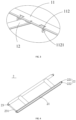
FIG. 2 is a perspective view of the mounting assembly ofFIG. 1 . -
FIG. 3 is a partial enlarged view ofFIG. 2 . -
FIG. 4 is a perspective view of the connection assembly ofFIG. 1 . -
FIG. 5 is a perspective view of the snap-fit assembly inFIG. 1 . -
FIG. 6 is a perspective view ofFIG. 1 with the connection assembly and the mounting assembly removed. -
FIG. 7 is a perspective view of the self-locking structure inFIG. 1 . -
FIG. 8 is a perspective view of the self-locking structure ofFIG. 7 from another angle. -
FIG. 9 is a perspective view of the second lock catch part inFIG. 1 . -
FIG. 10 is a perspective view of the lamp mounting structure according to second embodiment of the present application. -
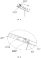
FIG. 11 is a perspective view of the mounting assembly ofFIG. 10 . -
FIG. 12 is a partial enlarged view ofFIG. 10 . -
FIG. 13 is another partial enlarged view ofFIG. 10 . -
FIG. 14 is a perspective view of the connection assembly ofFIG. 10 . -
FIG. 15 is a perspective view of the first connection assembly inFIG. 14 . -
FIG. 16 is a perspective view of the second connection assembly inFIG. 14 . -
FIG. 17 is a partial enlarged view ofFIG. 16 . -
FIG. 18 is another partial enlarged view ofFIG. 16 . -
FIG. 19 is a perspective view of the position limiting elastic piece and the disassembly assembly inFIG. 16 . -
FIG. 20 is a partial cross-sectional view ofFIG. 16 . -
FIG. 21 is a perspective view ofFIG. 10 with the connection assembly and the mounting assembly removed. -
FIG. 22 is a perspective view of the snap-fit assembly inFIG. 10 . -
FIG. 23 is a perspective view of the second lock catch part inFIG. 10 . - In order to make the purpose, technical solutions and advantages of the present application clearer, the present application will be described in detail below with reference to the accompanying drawings and specific embodiments.
- Here, it should be noted that, in order to avoid obscuring the present application with unnecessary details, only the structures and/or processing steps closely related to the solution of the present application are shown in the drawings, and other details that are less relevant to the present application are omitted.
- Additionally, it should be noted that the terms "comprise," "comprising," "include," "including," or any other variation thereof are intended to cover a non-exclusive inclusion, such that a process, method, article, or device that includes a list of elements includes not only those elements, but also includes other elements not expressly listed or includes that are inherent to the process, method, article or device.
- Please refer to
FIG. 1 to FIG. 9 , alamp mounting structure 100 is provided by the first embodiment of the present application. Thelamp mounting structure 100 includes amounting assembly 1, aconnection assembly 2, and achassis assembly 3. The mountingassembly 1 is fixedly installed on the mounting wall, and thechassis assembly 3 is fixedly connected to the lamp main body (not shown), and the mountingassembly 1, theconnection assembly 2, and thechassis assembly 3 are rotatably connected end-to-end in sequence to form a Z-shaped structure. This arrangement can solve the problems of poor viewing angle when aligning and installing the lamp, and at the same time realize the transposition requirements for suspended operations, making the installation process of lamps time-saving, labor-saving, efficient, safe, and can be installed and disassembled by a single person. - Please refer to
FIG. 2 , and in conjunction withFIG. 1 , the mountingassembly 1 is made of conventional plates and can be made into the required shape according to customer requirements and installation environment, such as round, square, I-shaped, etc., which is not limited by this application. In a preferred embodiment of the present application, the mountingassembly 1 includes a pair of first mountingparts 11 arranged in parallel and a second mountingpart 12 arranged vertically to the two first mountingparts 11 and arranged between the two first mountingparts 11. The two ends of the second mountingpart 12 are fixed to the middle parts of the two first mountingparts 11 respectively, so that the entire mountingassembly 1 has an I-shaped structure. By arranging the I-shaped mountingassembly 1, the mountingassembly 1 has a simplified structure, is convenient to produce, has the advantages of stable installation and strong load-bearing capacity, and can be widely used for installing various types of ceiling lamps, chandeliers and other lamps. Preferably, the two long sides of the first mountingpart 11 extend downwardly and inwardly from the edge part to the middle part, so that the first mountingpart 11 has an arc-shaped structure. A mountinghole 13 is provided in each first mountingpart 11, and the mountingassembly 1 is fixed on the mounting wall by using fasteners such as expansion screws. It can be understood that the mounting wall can be a wall, a suspended ceiling or a room ceiling, which is not limited in this application. - The mounting
assembly 1 is provided with a firstlock catch part 111, and thechassis assembly 3 is provided with at least one secondlock catch part 5 at a position corresponding to the firstlock catch part 111. The firstlock catch part 111 is connected with the secondlock catch part 5 in a lock catch manner. By arranging the locking engagement between the firstlock catch part 111 and the secondlock catch part 5, the installation difficulty of the lamp is reduced, the installation efficiency of the lamp is improved, single-person installation and disassembly is realized, and the installation cost is reduced. It should be noted that the specific number and arrangement positions of the firstlock catch parts 111 and the secondlock catch parts 5 are not limited in this application, as long as the firstlock catch part 111 and the secondlock catch part 5 are set correspondingly, and the firstlock catch part 111 and the secondlock catch part 5 can also be flexibly set according to the specific structure of the mountingassembly 1 and the lamp. - Please continue to refer to
FIG. 2 to FIG. 3 , the firstlock catch part 111 is provided on the side of the first mountingpart 11 away from the mounting wall. Four firstlock catch parts 111 are provided. Each firstlock catch part 111 is located at an end of the first mountingpart 11 and the firstlock catch parts 111 are symmetrically distributed on both sides of the first mountingpart 11. With this arrangement, the lamp can be hung on the mountingassembly 1 stably and with balanced force during the installation process. Of course, two firstlock catch parts 111 may also be provided. The two firstlock catch parts 111 are respectively provided on the first mountingpart 11 and are symmetrically provided on both sides of the second mountingpart 12. In addition, the firstlock catch part 111 may not be provided at the end of the first mountingpart 11, or may be provided at other positions of the first mountingpart 11, which is not limited in this application. - The end of each first mounting
part 11 at the side of the first mountingpart 11 away from the mounting wall extends downwardly to form an L-shaped firstlock catch part 111. Preferably, the L-shaped firstlock catch part 111 is an L-shaped hook. The horizontal extension direction of each hook is the same to facilitate locking engagement with the secondlock catch part 5 on thechassis assembly 3. Of course, the horizontal extension directions of the hooks located at the two ends of the first mountingpart 11 can also be different, as long as they can be connected with the secondlock catch part 5 in a locking manner. It should be noted that the firstlock catch part 111 can be integrally formed with the first mountingpart 11, or can be assembled and arranged on the first mountingpart 11. - Please refer to
FIG. 4 , theconnection assembly 2 includes a pair ofconnection rods 21 arranged in parallel and afirst connection part 22 and asecond connection part 23 located at both ends of theconnection rods 21. The mountingassembly 1 is rotatably connected to thefirst connection part 22, and thechassis assembly 3 is rotatably connected to thesecond connection part 23 to form a firstrotating part 223 and a secondrotating part 232 respectively. Such an arrangement can make theconnection assembly 2 have sufficient strength, and the lamp main body can be temporarily placed in the air to meet the transposition requirements of suspended operations. - The
first connection part 22 includes afirst connection hole 221 and aconnection piece 222. The side of the mountingassembly 1 away from the mounting wall extends downward at a position corresponding to thefirst connection part 22 to form a third connection part 112 (please refer toFIG. 2 andFIG. 3 ). Thethird connection part 112 is provided with asecond connection hole 1121 at a position corresponding to thefirst connection hole 221. Theconnection piece 222 passes through thefirst connection hole 221 and thesecond connection hole 1121 to rotatably connect the mountingassembly 1 and thefirst connection part 22. Theconnection piece 222 may be a rotating pin, a rotating rivet, a rotating shaft, etc., which is not limited in this application. Thefirst connection part 22 and thethird connection part 112 are rotatably connected through theconnection piece 222 so that theconnection assembly 2 can freely rotate around the firstrotating part 223 to drive thechassis assembly 3 to move closer to the mountingassembly 1. - The
second connection part 23 includes arotating shaft 231, and theconnection assembly 2 is rotatably connected to thechassis assembly 3 through therotating shaft 231. Theconnection assembly 2 can be directly and rotatably connected to thechassis assembly 3 through thesecond connection part 23, or can also be rotatably connected to thechassis assembly 3 through the snap-fit assembly 4. In one embodiment of the present application, a bracket (not shown) is provided on the side of thechassis assembly 3 facing theconnection assembly 2 at a position corresponding to thesecond connection part 23, and a third connection hole (not shown) is provided in the bracket. Therotating shaft 231 of thesecond connection part 23 passes through the third connection hole and is rotatably connected to the bracket. In order to improve the connection strength between theconnection assembly 2 and thechassis assembly 3, preferably, theconnection assembly 2 is rotatably connected to thechassis assembly 3 through the snap-fit assembly 4. - Please refer to
FIG. 5 , thelamp mounting structure 100 further includes a snap-fit assembly 4. The snap-fit assembly 4 is fixedly connected to the side of thechassis assembly 3 facing theconnection assembly 2 through welding, riveting fasteners, or the like. Thesecond connection part 23 is rotatably connected with thechassis assembly 3 through the snap-fit assembly 4. - The snap-
fit assembly 4 includes a first snap-fit member 41 and a second snap-fit member 42. Preferably, the first snap-fit member 41 is made of a hard material such as sheet metal, and the second snap-fit member 42 is made of an elastic material such as an elastic piece. Through the cooperation of the first snap-fit member 41 and the second snap-fit member 42, thesecond connection part 23 of theconnection assembly 2 is fixed in the snap-fit assembly 4, and thesecond connection part 23 can be freely rotated in the snap-fit assembly 4. - The first snap-
fit member 41 includes a plate-shaped first fixingpart 411. Thefirst fixing part 411 is fixedly connected to thechassis assembly 3 through fasteners. One end of the first fixingpart 411 close to theconnection assembly 2 is bent upward and inward to form abent part 412. A receivinggroove 413 is formed between thebent part 412 and the first fixingpart 411. Therotating shaft 231 of thesecond connection part 23 passes through the receivinggroove 413 and is rotatably connected to the first snap-fit member 41. The end of thebent part 412 extends obliquely towards a direction away from the first fixingpart 411 to form aguide part 414. Theguide part 414 can guide therotating shaft 231 of thesecond connection part 23 to quickly snap into the receivinggroove 413. - The second snap-
fit member 42 includes a plate-shaped second fixingpart 421, and thesecond fixing part 421 is fixedly connected to the first fixingpart 411. Preferably, a surface of thesecond fixing part 421 is attached on the first fixingpart 411, and thesecond fixing part 421 and the first fixingpart 411 are fixedly connected to thechassis assembly 3 through fasteners. The end of thesecond fixing part 421 close to thebent part 412 extends towards the interface part 415 where thebent part 412 and theguide part 414 are connected to form aposition limiting part 422. Theposition limiting part 422 is in contact with the interface part 415 for position limiting, so that therotating shaft 231 of thesecond connection part 23 is limited and fixed in the receivinggroove 413. Because the second snap-fit member 42 is an elastic piece, when therotating shaft 231 of thesecond connection part 23 enters the receivinggroove 413 under the guidance of theguide part 414 or when the rotating shaft is to be moved out of the receivinggroove 413, the elastic piece undergoes elastic deformation under the action of an external force, so as to facilitate therotating shaft 231 to enter the receivinggroove 413 or to move therotating shaft 231 out of the receivinggroove 413. When the external force disappears, the elastic deformation of the elastic piece disappears and the elastic piece returns to the original position. By arranging the second snap-fit member 42 to be made of elastic material, the connection and disassembly of theconnection assembly 2 and the snap-fit assembly 4 is facilitated and the installation efficiency is improved. - Please refer to
FIG. 6 , thechassis assembly 3 includes abottom plate 31 andside walls 32 surrounding thebottom plate 31 and located at a periphery of thebottom plate 31. Theside wall 32 extends in a direction from the periphery of thebottom plate 31 to a position close to the mountingassembly 1. Theside walls 32 and thebottom plate 31 jointly form a receivingspace 33 so as to receive the snap-fit assembly 4, the secondlock catch part 5, and theconnection assembly 2, so that thechassis assembly 3 can be installed on the mountingassembly 1 closely to improve the aesthetics of the lamp. - At least one second
lock catch part 5 is arranged on thechassis assembly 3 at a position corresponding to the firstlock catch part 111. The firstlock catch part 111 and the secondlock catch part 5 cooperate with each other in a lock catch manner to quickly lock thechassis assembly 3 with the mountingassembly 1 to complete the installation of the lamp. It can be understood that the shape of the secondlock catch part 5 can be realized by different structures, as long as it can be used and matched with the firstlock catch part 111. The number and position of the secondlock catch parts 5 also correspond to the firstlock catch parts 111, which are not limited by this application. - Please refer to
FIG. 7 to FIG. 8 , and in conjunction withFIG. 1 , in a preferred embodiment of the present application, the secondlock catch part 5 includes a self-lockingstructure 51 and adetachment assembly 52. Thedetachment assembly 52 includes a detachment button 521 and atransmission part 522. Through the locking engagement between the self-lockingstructure 51 and the firstlock catch part 111, and through the detachment button 521 and thetransmission part 522 quickly unlocking the locking engagement between the self-lockingstructure 51 and the firstlock catch part 111, quick installation and disassembly by a single person can be realized. - Please refer to
FIG. 7 to FIG. 8 , the self-lockingstructure 51 includes aslide rail 511, a slidingpart 512, anelastic member 513, and aposition limiting member 514. Theslide rail 511 includes a horizontal part 5111 parallel to the chassis structure and a pair ofposition limiting edges 5112 extending upward and bent from the edge of the horizontal part 5111. Theslide rail 511 is fixedly installed on thechassis assembly 3 through the horizontal part 5111. A slidingslot 5113 is formed between the horizontal part 5111 and theposition limiting edge 5112, and the slidingpart 512 is slidably connected to theslide rail 511 through the slidingslot 5113. Further, the slidingpart 512 includes a slidingcover 5121 and a side edge 5122 extending from an edge of the slidingcover 5121 towards a direction close to the horizontal part 5111. A pair of side edges 5122 corresponding to theposition limiting edge 5112 extends towards a connection direction of theposition limiting edge 5112 and the horizontal part 5111 to form a slidingedge 5123 parallel to the horizontal part 5111. The slidingedge 5123 is located and limited in the slidingslot 5113 under the action of theposition limiting edge 5112, and can slide freely in the slidingslot 5113. Abuckle part 5124 is provided at a position of the slidingpart 512 corresponding to the firstlock catch part 111 and is connected with the firstlock catch part 111 in a lock catch manner. Preferably, thebuckle part 5124 is an upside-down buckle that matches the L-shaped hook of the firstlock catch part 111. The firstlock catch part 111 and thebuckle part 5124 are locked and connected through the cooperation of the buckle and the hook. The side edge 5122 of the slidingpart 512 away from thebuckle part 5124 is provided with a throughhole 5125. Theposition limiting member 514 includes aposition limiting shaft 5141 and aposition limiting block 5142 vertically connected to theposition limiting shaft 5141. One end of theposition limiting shaft 5141 away from theposition limiting block 5142 passes through the throughhole 5125 and is slidably connected to the slidingpart 512. Theelastic member 513 is sleeved on theposition limiting shaft 5141 and is clamped between the slidingpart 512 and theposition limiting block 5142. Preferably, theelastic member 513 is a spring that maintains the tendency to return to its original position when subjected to elastic deformation. - Referring to
FIG. 9 , thetransmission part 522 includes afirst transmission part 5221 parallel to theside wall 32 of thechassis assembly 3 and asecond transmission part 5222 perpendicular to thefirst transmission part 5221. The fixing member passes through thethird fixing hole 322 to fixedly connect thefirst transmission part 5221 to theside wall 32 of thechassis assembly 3. The disassembly button 521 passes through thefirst fixing hole 321 in theside wall 32 of thechassis assembly 3 and is fixedly connected with thefirst transmission part 5221 of thetransmission part 522. The fixing member passes through thesecond fixing hole 5126 in the slidingcover 5121 to fixedly connect thesecond transmission part 5222 of thetransmission part 522 and the slidingcover 5121 to drive the slidingpart 512 to slide relative to theslide rail 511. - Furthermore, each self-locking
structure 51 can be provided with atransmission part 522 and a disassembly button 521. By pressing the disassembly button 521, the locking engagement between the secondlock catch part 5 and the firstlock catch part 111 can be quickly unlocked. Preferably, in order to save costs and improve disassembly efficiency, thetransmission part 522 is fixedly connected to the slidingparts 512 of the two self-lockingstructures 51 to drive the two slidingparts 512 to slide synchronously. - This application further provides a lamp, which includes a lamp main body (not shown) and the aforementioned
lamp mounting structure 100. The lamp main body and the side of thechassis assembly 3 facing away from theconnection assembly 2 are fixedly connected through fasteners such as screws. - When the lamp needs to be installed, first rotatably connect the
first connection part 22 of theconnection assembly 2 and the mountingassembly 1 through theconnection piece 222, then fix the mountingassembly 1 with theconnection assembly 2 on the mounting wall, and then fixedly install the snap-fit assembly 4 and the secondlock catch part 5 into the receivingspace 33 of thechassis assembly 3, and then fixedly connect the lamp main body to the side of thechassis assembly 3 facing away from theconnection assembly 2 through the fixing piece, then push up thechassis assembly 3 with the lamp main body so that thesecond connection part 23 of theconnection assembly 2 is rotatably connected to the snap-fit assembly 4. In this case, due to the effective engagement of theconnection assembly 2 and the snap-fit assembly 4, the lamp main body can be temporarily placed in the air to facilitate connection to the mains power, avoiding positioning difficulties due to line of sight, and improving visibility. Pushing thechassis assembly 3 upward again can cause thechassis assembly 3 to rotate around the firstrotating part 223 between theconnection assembly 2 and the mountingassembly 1, thereby realizing the upward rotational motion of the lamp main body around the rod, and at the same time realizing the transposition requirements for suspended operations. Through locking engagement of the secondlock catch part 5 and the firstlock catch part 111, the lamp main body is fixedly installed on the mountingassembly 1, and at the same time, theconnection assembly 2 is received in the receivingspace 33 of thechassis assembly 3, so as to improve the aesthetics of the lamp. - When it is necessary to disassemble the lamp main body, you only need to press the disassembly button 521. The disassembly button 521 drives the
transmission part 522 to move towards the slidingpart 512, so that the slidingcover 5121 moves on theposition limiting shaft 5141 towards theposition limiting block 5142, compressing theelastic member 513 to unlock the locking connection between thebuckle part 5124 and the firstlock catch part 111, and the lamp main body slowly leaves the mountingassembly 1, because theconnection assembly 2 and the snap-fit assembly 4 are effectively engaged, so that the lamp main body can be temporarily fixed in the air to prevent the lamp main body from falling quickly to damage the lamp main body or cause safety accidents, and to achieve quick installation and disassembly by one person. - Referring to
FIG. 10 to FIG. 23 , the second embodiment of the present application provides a lamp mounting structure 100', which includes: a mounting assembly 1', a connection assembly 2', and a chassis assembly 3'. The mounting assembly 1' is fixedly installed on the mounting wall, the chassis assembly 3' is fixedly connected to the lamp main body. The connection assembly 2' includes a first connection assembly 21' and a second connection assembly 22'. Both ends of the first connection assembly 21' are rotatably connected to the mounting assembly 1' and the chassis assembly 3', respectively, to form a first rotating part 2121' and a second rotating part 2131'; one end of the second connection assembly 22' is rotatably connected to an end of the first mounting part 11' away from the first rotating part 2121', and the other end of the second connection assembly 22' is rotatably connected to the second connection assembly 22' located between the first rotating part 2121' and the second rotating part 2131'. The mounting assembly 1' is provided with a first lock catch part 111', and a position of the chassis assembly 3' corresponding to the first lock catch part 111' is provided with at least one second lock catch part 5', and the first lock catch part 111' is connected with the second lock catch part 5' in a lock catch manner. By providing the connection assembly 2', the lamp can be installed in a time-saving, labor-saving, efficient and safe manner, especially for the lamp with a heavy weight. A single person can complete the installation and disassembly, which reduces the installation cost and avoids damage to the lamp during the installation process. Through the relative sliding and locking connection between the first sliding part 221' and the second sliding part 222' and the relative sliding, relative rotation and buckle connection between the first connection assembly 21' and the second connection assembly 22', it can realize the up and down reciprocating movement of the entire lamp mounting structure 100' and the space storage effect of the connection assembly 2'. Moreover, it can realize the self-locking effect of the lamp, avoid the risk of falling during installation process, and improve the convenience of installation. - Please refer to
FIG. 11 to FIG. 13 , the structure of the mounting assembly 1' of the present application is basically the same as that of first embodiment, and will not be described in detail here. The mounting assembly 1' includes a pair of first mounting parts 11' parallel to each other and a second mounting part 12' perpendicular to the first mounting parts 11' and located between the first mounting parts 11'. The first mounting part 11' is provided with a first lock catch part 111', the chassis assembly 3' is provided with at least one second lock catch part 5' at a position corresponding to the first lock catch part 111', and the first lock catch part 111' is connected with the second lock catch part 5' in a lock catch manner. By arranging the locking engagement between the first lock catch part 111' and the second lock catch part 5', the installation difficulty of the lamp is reduced, the installation efficiency of the lamp is improved, single-person installation and disassembly is realized, and the installation cost is reduced. It should be noted that the specific number and arrangement positions of the first lock catch parts 111' and the second lock catch parts 5' are not limited in this application, as long as the first lock catch part 111' and the second lock catch part 5' are arranged correspondingly, and the first lock catch part 111' and the second lock catch part 5' can also be flexibly determined according to the specific structure of the mounting assembly 1 ' and the lamp. - Preferably, a first lock catch part 111' is provided on the side of the first mounting part 11' facing away from the mounting wall. There are four first lock catch parts 111', each first lock catch part 111' is located at the end of the first mounting part 11', and first lock catch parts 111' are symmetrically distributed on both sides of the first mounting part 11'. With such an arrangement, the lamp can be hung on the mounting assembly 1' smoothly and with balanced force during the installation process.
- Same as first embodiment, the end of each first mounting part 11' at the side of the first mounting part 11' away from the mounting wall extends downwardly to form an L-shaped first lock catch part 111'. Preferably, the L-shaped first lock catch part 111' is an L-shaped hook. The horizontal extension directions of respective hooks are the same to facilitate locking engagement with the second lock catch part 5' on the chassis assembly 3'. The first lock catch part 111' is further provided with a second locking hole 114' for cooperating with the first locking hole 321' in the chassis assembly 3' to fixedly connect the chassis assembly 3' and the mounting assembly 1'.
- Please refer to
FIG. 13 in conjunction withFIG. 11 . The difference between the second embodiment and the first embodiment is that a fourth connection part 113' is arranged on the first installation part 11' that is not provided with the third connection part 112' at the position corresponding to the second connection assembly 22'. The end of the second connection assembly 22' away from the first connection assembly 21' is used to rotatably connect the first mounting part 11' and the second connection assembly 22' through a connection piece, so that the second connection assembly 22' can be rotated relative to the mounting assembly 1'. - Please refer to
FIG. 14 , the connection assembly 2' of the present application includes a first connection assembly 21' and a second connection assembly 22'. The two ends of the first connection assembly 21' are rotatably connected to the mounting assembly 1' and the chassis assembly 3', respectively to form a first rotating part 2121' and a second rotating part 2131'. One end of the second connection assembly 22' is rotatably connected to the end of the first mounting part 11' away from the first rotating part 2121', and the other end of the second connection assembly 22' is rotatably connected to the connection assembly 22' located between the first rotating part 2121' and the second rotating part 2131'. - Please refer to
FIG. 15 , the first connection assembly 21' has a structure similar to that of the connection assembly 2' in first embodiment, and includes a pair ofconnection rods 211' parallel to each other and a first connection part 212' and a second connection parts 213' located at both ends of theconnection rod 211', the mounting assembly 1' is rotatably connected to the first connection part 212', and the chassis assembly 3' is rotatably connected to the second connection part 213' to form the first rotating part 2121' and the second rotating part, respectively. A gap is provided between the twoconnection rods 211' of the first connection assembly 21', and the gap is used to receive the second connection assembly 22', so as to facilitate the space storage effect of the connection assembly 2' after the lamp is installed. - Please refer to
FIG. 16 to FIG. 20 , the second connection assembly 22' includes a first sliding part 221' and a second sliding part 222'. The first sliding part 221' is rotatably connected to the fourth connection part 113' of the mounting assembly 1' through a connection piece. The connection piece can be a rotating pin, a rotating rivet or a rotating shaft, etc., which is not limited to this in this application. The second sliding part 222' is rotatably connected to the second connection assembly 22' located between the first rotating part 2121' and the second rotating part 2131' through a second rotating shaft. - Furthermore, a guide groove 2211' is provided on the side of the first sliding part 221', and the guide groove 2211' extends from the connection position between the first sliding part 221' and the second sliding part 222' towards a direction close to the fourth connection part 113'. The second sliding part 222' is provided with a first guide shaft 2211' that is matched and connected with the guide groove 2211'. The first sliding part 221' and the second sliding part 222' can slide relative to each other through the cooperation of the guide groove 2211' and the first guide shaft 2211', so as to drive the second sliding part 222' and to move towards the first sliding part 221' to retract.
- Please refer to
FIG. 16 to FIG. 20 , the first sliding part 221' is further provided with a plurality of position limiting grooves 2212', and the plurality of position limiting grooves 2212' are spaced apart in a direction parallel to the first guide shaft 2211'. A position limiting elastic piece 2222' is provided at one end of the second sliding part 222' close to the first guide shaft 2211'. One end of the position limiting elastic piece 2222' is bent upward to form a buckle part 2223'. When the relative sliding between the second sliding part 222' and the first sliding part 222' parts 221' is stopped, the second sliding part 222' moves downward due to gravity, at this time, the buckle part 2223' of the position limiting elastic piece 2222' is automatically inserted into the position limiting groove 2212' closest to the position limiting elastic piece 2222' under the action of elastic force. The position limiting elastic piece 2222' is locked with the position limiting groove 2212' to complete the self-locking effect between the first sliding part 221' and the second sliding part 222'. - Further, one end of the second sliding part 222' away from the position limiting groove 2212' is rotatably connected to the first connection assembly 21' through the second guide shaft 214'. Specifically, a second guide rotating shaft 215' is fixedly arranged on the first connection assembly 21', and a rotating shaft slide groove 2224' is provided at one end of the second sliding part 222' close to the first connection assembly 21'. The second guide shaft 214' passes through the rotating shaft slide groove 2224', so that the second sliding part 222' can slide relative to the first connection assembly 21'. Preferably, a gap 2226' is provided between the top of the stuck slot 2225' and the top of the side surface of the rotating shaft slide groove 2224', and the second guide shaft 214' can slide relatively in the rotating shaft slide groove 2224' through the gap 2226'. Further, the stuck slot 2225' is provided at the bottom of the side surface of the rotating shaft slide groove 2224', and the stuck slot 2225' is snap-connected to the second guide shaft 214'. When an external force is applied to the second sliding part 222', the second guide shaft 214' relatively slides in the rotating shaft slide groove 2224' through the gap 2226' under the action of the external force. When the external force is quickly released, under the action of the gravity of the lamp main body, the second guide shaft 214' falls into the stuck slot 2225' in the rotating shaft slide groove 2224', and is connected with the stuck slot 2225' in a snap manner, so that the second sliding part 222' and the first connection assembly 21' complete self-locking effect.
- Please refer to
FIG. 19 to FIG. 20 , the lamp mounting structure 100' further includes a detachment assembly 52'. One end of the detachment assembly 52' is fixedly connected to the buckle part 2223', and the other end of the detachment assembly 52' extends out from the detachment hole in the second sliding part 222'. Preferably, the disassembly assembly 52' is a steel wire rivet. The steel wire is wrapped around the rivet. The rivet is fixedly connected to the buckle part 2223' of the position limiting elastic piece 2222'. The steel wire penetrates the position limiting elastic piece 2222' and the second sliding part 222' to protrude outward. The outward protruding part is received in the receiving space 33' of the chassis assembly 3', and the aesthetics of the lamp mounting structure 100' can be improved by setting rubber plugs on the protruding part, and can avoid being scratched or damaged by steel wires during the installation and disassembly process. When the steel wire rivet is pulled, the position limiting elastic piece 2222' can slide out from the position limiting groove 2212' to unlock the locking connection between the first sliding part 221' and the second sliding part 222'. At the same time, during the slow descent of the lamp main body, the first connection assembly 21' and the second connection assembly 22' are unlocked synchronously with the help of the weight of the lamp main body. By providing the disassembly assembly 52', the locking connection between the first sliding part 221' and the second sliding part 222' and the snap-fit connection between the first connection assembly 21' and the second connection assembly 22' can be easily released, thereby achieving free installation and tool-free disassembly. - Please refer to
FIG. 21 , the chassis assembly 3' includes a bottom plate 31' and side walls 32' surrounding the bottom plate 31' and located at a periphery of the bottom plate 31'. The side walls 32' extend from a periphery of thebottom plate 3 1' towards a direction close to the mounting assembly 1'. The walls 32' and the bottom plate 31' jointly form a receiving space 33' to receive the snap-fit assembly 4', the second lock catch part 5', and the connection assembly 2', so that the chassis assembly 3' can be installed on the mountingassembly 1 in a tight fit manner to improve the aesthetics of the lamp. - Please refer to
FIG. 22 , and in conjunction withFIG. 21 , the lamp mounting structure 100' further includes a snap-fit assembly 4', which is fixedly connected to the side of the chassis assembly 3' facing the connection assembly 2', and the end of the first connection assembly 21' away from the mounting assembly 1' is rotatably connected to the chassis assembly 3' through the snap-fit assembly 4'. The snap-fit assembly 4' may be the same as the snap-fit assembly 4' of first embodiment, or may be different, which is not limited in this application. Preferably, in this embodiment, the snap-fit assembly 4' is not exactly the same as the first embodiment. The snap-fit assembly 4' is not provided with the second snap-fit assembly 4', but is bent downward and inward at the intersection of the bent part 412' and the guide part 414' for limiting the rotating shaft 215' in the receiving groove 413'. Of course, the snap-fit assembly 4' can also be configured in other structures, as long as it can be effectively engaged with the connection assembly 2' to fix the lamp main body in the air and meet the transposition requirements for suspended operations. - Please refer to
FIG. 23 and in conjunction withFIG. 21 , the second lock catch part 5' of the second embodiment of the present application is shown. The second lock catch part 5' includes a joint part 511', a vertical part 512', and a clamping part 513' that are connected in sequence. The joint part 511' is fixedly connected to the chassis assembly 3', the vertical part 512' is perpendicular to the joint part 511', and the end of the vertical part 512' away from the joint part 511' is bent in a direction close to the vertical part 512' to form a clamping part 513', the clamping part 513' is connected to the first lock catch part 111' in a snap-fit manner to complete the locking connection between the chassis assembly 3' and the mounting assembly 1'. - The present application further provides a lamp with the aforementioned lamp mounting structure 100', including a lamp main body and the aforementioned lamp mounting structure 100'. The lamp main body is fixedly connected to the side of the chassis assembly 3' away from the connection assembly 2'.
- When the lamp needs to be installed, first rotatably connect the first connection part 212' of the first connection assembly 21' and the first sliding part 221' of the second connection assembly 22' to the third connection part 112' and the fourth connection part 113' of the mounting assembly 1', respectively, through the connection pieces, and then fixedly connect the mounting assembly 1' with the connection assembly 2' to the mounting wall, and then fixedly install the snap-fit assembly 4' and the second lock catch part 5' into the receiving space 33' of the chassis assembly 3', then fixedly connect the lamp main body to the side of the chassis assembly 3' away from the connection assembly 2' through a fixing piece. Pushing up the chassis assembly 3' with the lamp main body is performed so that the second connection part 213' of the second connection assembly 22' is rotatably connected to the snap-fit assembly 4'.
- At this time, due to the effective engagement of the connection assembly 2' and the snap-fit assembly 4', the lamp main body can be temporarily placed in the air to facilitate connection to the mains power, avoiding positioning difficulties due to line of sight, and providing higher visibility. When the chassis assembly 3' is pushed upward, due to the lateral separation between the first connection assembly 21' and the second connection assembly 22', the second sliding part 222' of the first connection assembly 21' slides inward relative to the first sliding part 221', stop pushing when it reaches a certain installation position. Because the external force disappears, the second sliding part 222' moves downward due to gravity, and the position limiting elastic piece 2222' automatically snaps into the nearest position limiting groove 2212' under the action of elastic force, to complete the self-locking effect of the first sliding part 221' and the second sliding part 222'. At this time, under the gravity of the lamp main body, the second guide shaft 214' falls into the
stuck slot 2225 in the rotating shaft slide groove 2224', and is snap-connected with the stuck slot 2225', so that the second sliding part 222' and the first connection assembly 21' complete the self-locking effect. With this arrangement, the lamp main body can be self-locked and stopped in the air at any time to facilitate connection to mains power or maintenance. Continue to push the chassis assembly 3' upward until the first guide shaft 2211' of the second sliding part 222' contacts the highest point of the guide groove 2211' of the first sliding part 221'. At this time, the first connection assembly 21' moves around the guide groove 2211' of the second connection assembly 22' with the second guide shaft 214' as a fulcrum to perform relatively sliding. The second connection assembly 22' is received in the first connection assembly 21'. The secondlock catch part 5 in the chassis assembly 3' completes the locking connection with the first lock catch part 111' of the mounting assembly 1 '. - At this time, the fastener passes through the first locking hole 321' in the chassis assembly 3' and the second locking hole 114' in the mounting assembly 1', and the chassis assembly 3' and the mounting assembly 1' are fastened and fixed again, to improve the stability of the lamp.
- When it is necessary to disassemble the lamp main body, remove the fasteners, remove the rubber plug, pull down the wire rivet, and the position limiting elastic piece 2222' slides downward from the position limiting groove 2212' to unlock the locking connection between the first sliding part 221' and the second sliding part 222'. At the same time, during the slow descent of the lamp main body, the first connection assembly 21' and the second connection assembly 22' are synchronously unlocked with the help of the weight of the lamp main body. Moreover, due to the unique connection method between the mounting assembly 1', the connection assembly 2', and the chassis assembly 3', when the first connection assembly 21' and the second connection assembly 22' are unlocked, the lamp main body is transposed at high altitude to unlock the locking connection between the clamping part and the first lock catch part 111', and the lamp main body slowly leaves the mounting assembly 1'. Because of the effective engagement between the connection assembly 2' and the snap-fit assembly 4', the lamp main body can be temporarily fixed in the air, thereby preventing the lamp main body from falling rapidly, which may damage the lamp main body or cause safety accidents, and enabling quick installation and disassembly by one single person.
- To sum up, in the
lamp mounting structure 100 of the present application and the lamp with thelamp mounting structure 100, by rotatably connecting the mountingassembly 1, theconnection assembly 2, and thechassis assembly 3 end-to-end in sequence to form a Z-shaped structure, solving the problems of poor viewing angle when aligning and installing the lamp, and at the same time realizing the transposition requirement for suspended operations, making the installation process of lamps time-saving, labor-saving, efficient, and safe. Especially when installing heavy lamps, a single person can complete the installation and disassembly, thereby reducing the installing cost, and avoiding damage to lamps during installation. By arranging the guide of theconnection assembly 2 and operating of the disassembly button 521, the installation efficiency can be improved, and the visibility of the installation process is high. In addition, thelamp mounting structure 100 and the lamp of the present application can be installed independently and sold independently, thereby improving the versatility of respective structures and reducing the cost of the lamp. - The above embodiments are only used to illustrate the technical solutions of the present application and are not construed as any limitation thereto. Although the present application has been described in detail with reference to the preferred embodiments, those of ordinary skill in the art should understand that the technical solutions of the present application can be modified or equivalently substituted without departing from the spirit and scope of the technical solution of this application.
Claims (10)
- A lamp mounting structure, for assembling a lamp on a mounting wall, comprising: a mounting assembly, a connection assembly, and a chassis assembly, the mounting assembly is fixedly installed on the mounting wall, the chassis assembly is fixedly connected to a lamp main body, the mounting assembly, the connection assembly, and the chassis assembly are rotatably connected end-to-end in sequence to form a Z-shaped structure, the mounting assembly is provided with a first lock catch part, and at least one second lock catch part is provided on the chassis assembly at a position corresponding to the first lock catch part, and the first lock catch part is connected to the second lock catch part in a lock catch manner.
- The lamp mounting structure according to claim 1, wherein the connection assembly comprises a pair of connection rods arranged in parallel and a first connection part and a second connection part respectively located at both ends of the connection rods, and the mounting assembly is rotatably connected with the first connection part, and the chassis assembly is rotatably connected with the second connection part.
- The lamp mounting structure according to claim 2, wherein the first connection part comprises a first connection hole and a connection piece, and a side of the mounting assembly away from the mounting wall extends downward at a position corresponding to the first connection part to form a third connection part, and a second connection hole is provided in the third connection part at a position corresponding to the first connection hole, and the connection piece passes through the first connection hole and the second connection hole to rotatably connect the mounting assembly and the first connection part.
- The lamp mounting structure according to claim 2, wherein the lamp mounting structure further comprises a snap-fit assembly, the snap-fit assembly is fixedly connected to a side of the chassis assembly facing the connection assembly, and the second connection part is rotatably connected to the chassis assembly through the snap-fit assembly.
- The lamp mounting structure according to claim 4, wherein the snap-fit assembly comprises a first snap-fit member and a second snap-fit member, the first snap-fit member comprises a first fixing part, and the first fixing part is fixedly connected to the chassis assembly, one end of the first fixing part is bent upward and inward to form a bent part, a receiving groove is formed between the bent part and the first fixing part, and a rotating shaft of the second connection part passes through the receiving groove and is rotatably connected to the first snap-fit member.
- The lamp mounting structure according to claim 5, wherein an end of the bent part extends towards a direction away from the first fixing part to form a guide part, and the second snap-fit member comprises a second fixing part, the second fixing part is fixedly connected to the first fixing part, and an end of the second fixing part close to the bent part extends towards an interface part where the bent part and the guide part are connected to form a position limiting part, the position limiting part is in contact with the interface part for position limiting.
- The lamp mounting structure according to claim 1, wherein the second lock catch part comprises a self-locking structure, the self-locking structure comprises a slide rail, a sliding part, an elastic member, and a position limiting member, and the slide rail is fixedly installed on the chassis assembly and is slidably connected with the sliding part, a position of the sliding part corresponding to the first lock catch part is provided with a buckle part that is connected with the first lock catch part in a lock catch manner, and a side of the sliding part away from the buckle part is provided with a through hole, the position limiting member comprises a position limiting shaft and a position limiting block vertically connected to the position limiting shaft, one end of the position limiting shaft away from the position limiting block passes through the through hole and is slidably connected to the sliding part, the elastic member is sleeved on the position limiting shaft and is clamped between the sliding part and the position limiting block.
- The lamp mounting structure according to claim 7, wherein the second lock catch part further comprises a detachment assembly, the detachment assembly comprises a detachment button and a transmission part, the transmission part is fixedly connected to the sliding part, and the disassembly button passes through the first fixing hole in a side wall of the chassis assembly and is fixedly connected to the transmission part to drive the sliding part to slide relative to the slide rail.
- The lamp mounting structure according to claim 8, wherein the transmission part is fixedly connected to sliding parts of two self-locking structures to drive the two sliding parts to slide synchronously.
- A lamp, comprising: a lamp main body and a lamp mounting structure according to any one of claims 1 to 9, wherein the lamp main body is fixedly connected to a side of the chassis assembly away from the connection assembly.
Applications Claiming Priority (3)
| Application Number | Priority Date | Filing Date | Title |
|---|---|---|---|
| CN202110917473.8A CN113587056B (en) | 2021-08-11 | 2021-08-11 | Lamp installation structure and lamp |
| CN202121867723.3U CN215929499U (en) | 2021-08-11 | 2021-08-11 | Lamp mounting structure and lamp |
| PCT/CN2022/111311 WO2023016475A1 (en) | 2021-08-11 | 2022-08-10 | Lamp mounting structure and lamp |
Publications (2)
| Publication Number | Publication Date |
|---|---|
| EP4386258A1 true EP4386258A1 (en) | 2024-06-19 |
| EP4386258A4 EP4386258A4 (en) | 2024-10-16 |
Family
ID=85199826
Family Applications (1)
| Application Number | Title | Priority Date | Filing Date |
|---|---|---|---|
| EP22855456.4A Pending EP4386258A4 (en) | 2021-08-11 | 2022-08-10 | Lamp mounting structure and lamp |
Country Status (3)
| Country | Link |
|---|---|
| US (1) | US20240240779A1 (en) |
| EP (1) | EP4386258A4 (en) |
| WO (1) | WO2023016475A1 (en) |
Family Cites Families (10)
| Publication number | Priority date | Publication date | Assignee | Title |
|---|---|---|---|---|
| JP2004171900A (en) * | 2002-11-19 | 2004-06-17 | Toshiba Lighting & Technology Corp | Lighting equipment lifting equipment, lighting equipment |
| US9464790B2 (en) * | 2012-05-08 | 2016-10-11 | Cooper Technologies Company | Systems, methods, and devices for providing rotatable light modules and hinged mount in a luminaire |
| CN203336496U (en) * | 2013-07-08 | 2013-12-11 | 东莞金准电器有限公司 | A push-type transfer hook |
| KR20160006001A (en) * | 2014-07-08 | 2016-01-18 | 동부라이텍 주식회사 | Lighting installation assembly |
| CN204387865U (en) * | 2015-01-13 | 2015-06-10 | 欧普照明股份有限公司 | A kind of light fixture |
| KR101942327B1 (en) * | 2018-03-09 | 2019-01-25 | 박병기 | A Lighting Device |
| US11041611B2 (en) * | 2019-10-28 | 2021-06-22 | Abl Ip Holding Llc | Lighting unit mounting assembly and method |
| CN111981368A (en) * | 2020-08-31 | 2020-11-24 | 深圳市兆驰照明股份有限公司 | Ceiling lamp with latch mechanism |
| CN215929499U (en) * | 2021-08-11 | 2022-03-01 | 欧普照明股份有限公司 | Lamp mounting structure and lamp |
| CN113551206B (en) * | 2021-08-11 | 2025-03-21 | 欧普照明股份有限公司 | Lamp installation structure and lamp |
-
2022
- 2022-08-10 WO PCT/CN2022/111311 patent/WO2023016475A1/en not_active Ceased
- 2022-08-10 EP EP22855456.4A patent/EP4386258A4/en active Pending
-
2024
- 2024-02-09 US US18/437,529 patent/US20240240779A1/en active Pending
Also Published As
| Publication number | Publication date |
|---|---|
| US20240240779A1 (en) | 2024-07-18 |
| EP4386258A4 (en) | 2024-10-16 |
| WO2023016475A1 (en) | 2023-02-16 |
Similar Documents
| Publication | Publication Date | Title |
|---|---|---|
| US5758959A (en) | Recessed lamp fixture | |
| US10537032B2 (en) | Mounting structure for display screen | |
| US11168872B2 (en) | Mounting clip for networked LED lighting system | |
| CN113587056B (en) | Lamp installation structure and lamp | |
| CN110670784B (en) | Stable suspended ceiling structure | |
| WO2017088356A1 (en) | Wall-mounting device for display device and display device | |
| US20250224099A1 (en) | Mounting accessories for luminaires | |
| US10788162B2 (en) | Retrofit kit and methods for conversion of fluorescent light assemblies to LED assemblies | |
| CN113551206B (en) | Lamp installation structure and lamp | |
| CN215929498U (en) | Lamp installation structure and lamps | |
| CN215929499U (en) | Lamp mounting structure and lamp | |
| US20240240779A1 (en) | Lamp mounting structure and lamp | |
| CN113251360B (en) | Ceiling lamp installation structure, ceiling lamp and ceiling lamp installation method | |
| CN216591361U (en) | Ceiling lamp mounting structure and ceiling lamp | |
| US8109648B2 (en) | Light fixture having socket track assemblies with detachable row aligner | |
| EP4368881A1 (en) | Lamp mounting structure and lamp | |
| KR20200132033A (en) | Mount assembly for lamp | |
| KR20140074497A (en) | ceiling lamps | |
| CN113932174A (en) | Ceiling lamp mounting structure and ceiling lamp | |
| US11473744B1 (en) | Panel lamp | |
| US8342722B1 (en) | Light system | |
| KR200493425Y1 (en) | Ceiling light | |
| CN113251359B (en) | Ceiling light installation structure, ceiling lights and their installation methods | |
| KR20210000086U (en) | Ceiling light | |
| US20200088388A1 (en) | Ceiling interface for luminaires |
Legal Events
| Date | Code | Title | Description |
|---|---|---|---|
| STAA | Information on the status of an ep patent application or granted ep patent |
Free format text: STATUS: THE INTERNATIONAL PUBLICATION HAS BEEN MADE |
|
| PUAI | Public reference made under article 153(3) epc to a published international application that has entered the european phase |
Free format text: ORIGINAL CODE: 0009012 |
|
| STAA | Information on the status of an ep patent application or granted ep patent |
Free format text: STATUS: REQUEST FOR EXAMINATION WAS MADE |
|
| 17P | Request for examination filed |
Effective date: 20240311 |
|
| AK | Designated contracting states |
Kind code of ref document: A1 Designated state(s): AL AT BE BG CH CY CZ DE DK EE ES FI FR GB GR HR HU IE IS IT LI LT LU LV MC MK MT NL NO PL PT RO RS SE SI SK SM TR |
|
| REG | Reference to a national code |
Ref country code: DE Ref legal event code: R079 Free format text: PREVIOUS MAIN CLASS: F21V0021140000 Ipc: F21V0021260000 |
|
| A4 | Supplementary search report drawn up and despatched |
Effective date: 20240913 |
|
| RIC1 | Information provided on ipc code assigned before grant |
Ipc: F21V 21/03 20060101ALN20240909BHEP Ipc: F21S 8/04 20060101ALN20240909BHEP Ipc: F21V 21/36 20060101ALI20240909BHEP Ipc: F21V 21/30 20060101ALI20240909BHEP Ipc: F21V 21/02 20060101ALI20240909BHEP Ipc: F21V 21/26 20060101AFI20240909BHEP |
|
| DAV | Request for validation of the european patent (deleted) | ||
| DAX | Request for extension of the european patent (deleted) |