EP4386245A1 - Système de fixation à manchon - Google Patents
Système de fixation à manchon Download PDFInfo
- Publication number
- EP4386245A1 EP4386245A1 EP23215286.8A EP23215286A EP4386245A1 EP 4386245 A1 EP4386245 A1 EP 4386245A1 EP 23215286 A EP23215286 A EP 23215286A EP 4386245 A1 EP4386245 A1 EP 4386245A1
- Authority
- EP
- European Patent Office
- Prior art keywords
- cylinder
- link
- tunnel
- hole
- sleeve fixing
- Prior art date
- Legal status (The legal status is an assumption and is not a legal conclusion. Google has not performed a legal analysis and makes no representation as to the accuracy of the status listed.)
- Granted
Links
Images


Classifications
-
- F—MECHANICAL ENGINEERING; LIGHTING; HEATING; WEAPONS; BLASTING
- F16—ENGINEERING ELEMENTS AND UNITS; GENERAL MEASURES FOR PRODUCING AND MAINTAINING EFFECTIVE FUNCTIONING OF MACHINES OR INSTALLATIONS; THERMAL INSULATION IN GENERAL
- F16L—PIPES; JOINTS OR FITTINGS FOR PIPES; SUPPORTS FOR PIPES, CABLES OR PROTECTIVE TUBING; MEANS FOR THERMAL INSULATION IN GENERAL
- F16L5/00—Devices for use where pipes, cables or protective tubing pass through walls or partitions
-
- F—MECHANICAL ENGINEERING; LIGHTING; HEATING; WEAPONS; BLASTING
- F16—ENGINEERING ELEMENTS AND UNITS; GENERAL MEASURES FOR PRODUCING AND MAINTAINING EFFECTIVE FUNCTIONING OF MACHINES OR INSTALLATIONS; THERMAL INSULATION IN GENERAL
- F16L—PIPES; JOINTS OR FITTINGS FOR PIPES; SUPPORTS FOR PIPES, CABLES OR PROTECTIVE TUBING; MEANS FOR THERMAL INSULATION IN GENERAL
- F16L41/00—Branching pipes; Joining pipes to walls
- F16L41/08—Joining pipes to walls or pipes, the joined pipe axis being perpendicular to the plane of a wall or to the axis of another pipe
-
- F—MECHANICAL ENGINEERING; LIGHTING; HEATING; WEAPONS; BLASTING
- F16—ENGINEERING ELEMENTS AND UNITS; GENERAL MEASURES FOR PRODUCING AND MAINTAINING EFFECTIVE FUNCTIONING OF MACHINES OR INSTALLATIONS; THERMAL INSULATION IN GENERAL
- F16L—PIPES; JOINTS OR FITTINGS FOR PIPES; SUPPORTS FOR PIPES, CABLES OR PROTECTIVE TUBING; MEANS FOR THERMAL INSULATION IN GENERAL
- F16L5/00—Devices for use where pipes, cables or protective tubing pass through walls or partitions
- F16L5/02—Sealing
- F16L5/027—Sealing by means of a joint of the quick-acting type
Definitions
- the present invention relates to a sleeve fixing system for fixing pipes through a support such as a beam, as well as an assembly comprising a beam, pipes and such a sleeve fixing system.
- An object of the present invention is to provide a sleeve fixing system which is arranged to be fixed within a hole passing through a joist.
- the cylinder carries a diversion pipe which is arranged on the side of the first opening in relation to the collar and which opens into the interior of the cylinder.
- the link takes the form of a self-locking clamp with teeth, and the hooking means has an anti-return pawl which cooperates with the teeth to block the removal of the link.
- the pawl is mounted on an elastic arm of the hooking means.
- the holding system comprises a support which extends the support surface towards the collar and intended to penetrate into the hole by passing between the roof of the tunnel and the surface of the hole.
- Fig. 1 shows an assembly 100 which includes a beam 102, here an IPE type beam, but any other type of beam is possible.
- a beam 102 here an IPE type beam, but any other type of beam is possible.
- the beam 102 includes a core 104 which is crossed by at least one hole 106a-b.
- a hole 106a of circular shape and a hole 106b of elliptical shape are possible.
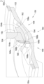
- the assembly 100 also includes a sleeve fixing system 150, one embodiment of which is shown in Fig. 2 and which is fixed to the beam 102 and receives two pipes 50a-b of said assembly 100 which are shown in partial section and in ghost lines on the Fig. 2 .
- the sleeve fixing system 150 consists of a flange 154 and a cylinder 152 having an axis X.
- the flange 154 is integral with the wall of the cylinder 152 and extends coaxially around said wall of the cylinder 152 so as to form an outer peripheral rib.
- the collar 154 is at a distance from each end of the cylinder 152 to allow the fitting of a pipe 50a-b on each of said ends, that is to say on either side of the collar 154.
- the wall of the cylinder 152 is dug with at least one tunnel 156 which has a first and a second openings 156a-b which open onto the exterior of the wall of the cylinder 152 and on either side of the collar 154.
- Each tunnel 156 extends parallel to the axis X.
- each tunnel 156 is sealed with respect to the interior of the cylinder 152. If the thickness of the wall of the cylinder 152 is sufficient, each tunnel 156 is dug in said wall of the cylinder 152 and if the thickness is insufficient, a reinforcement 158 is provided inside the wall of the cylinder 152 in order to sealingly delimit each tunnel 156.
- the wall of the cylinder 152, each reinforcement 158 and the tunnel 156 associated are conventionally made by molding a plastic material.
- the sleeve fixing system 150 comprises a holding system 160, 260, different embodiments of which are described below and which ensures the fixing of the cylinder 152 on the beam 102.
- one end of the cylinder 152 is fitted into a hole 106a-b of the core 104 of the beam 102 so as to bring the collar 154 against the edge of the hole 106a- b and against the core 104.
- the diameter of the collar 154 is greater than the internal dimension of the hole 106a-b to be able to lean against the beam 102.
- the collar 154 thus has a support face 154a ( Figs. 3 And 4 ) which rests against the beam 102 and a free face 154b opposite.
- the holding system 160, 260 comprises a link 164 and a shoe 162 secured to a first end of the link 164.
- the link 164 is housed in the tunnel 156 and has a second end which is opposite the shoe 162 and which is introduced into the tunnel 156 through the first opening 156a which is on the side of the free face 154b of the collar 154 to exit through the second opening 156b on the side of the support face 154a.
- the dimensions of the shoe 162 and the tunnel 156 are such that the shoe 162 cannot pass through the tunnel 156 and the shoe 162 is thus blocked at the level of the first opening 156a.
- the link 164 is preferably flexible to facilitate passage through the tunnel 156 and its second end exits through the second opening 156b.
- the holding system 160, 260 comprises a locking system 166, 266 which comprises a bearing surface 166a, 266a which, in use, bears against the core 104 of the beam 102 opposite the face d support 154a relative to the beam 102, and a hooking means 166b, 266b which attaches to the second end of the link 164 so as to block the link 164 in the tunnel 156 and thus prevent the removal of said link 164 at all by ensuring the tightening of the bearing surface 166a, 266a against the core 104.
- the second end of the link 164 is pulled so as to block the shoe 162 at the level of the first opening 156a of the tunnel 156, then the locking system 166, 266 is moved along the link 164 of its second end towards its first end so as to bring the support surface 166a, 266a against the beam 102 and thus tighten the beam 102 between the support face 154a of the collar 154 and the support surface 166a, 266a of the locking system 166, 266.
- the hooking means 166b, 266b attaches to the second end of the link 164 to block the shoe 162 and the support surface 166a, 266a.
- Each pipe 50a-b is fitted tightly onto one end of the cylinder 152.
- the seal is achieved by any appropriate means, such as for example the installation and tightening of a circular clamp around the pipe 50a- b, in particular in the case of a flexible pipe 50a-b, but the sealing can also be achieved by gluing, or the establishment of a seal between the cylinder 152 and the pipe 50a-b.
- the sleeve fixing system 150 is housed in a hole 106a-b of the beam 102 and no longer encroaches on the space available above or below said beam 102.
- the cylinder 152 carries a diversion pipe 202 which is arranged on the side of the first opening 156a relative to the flange 154, that is to say on the side opposite the support face 154a and which opens to the interior of the cylinder 152 and makes it possible to fluidly connect a diversion pipe.
- Fig. 3 shows a particular embodiment of the holding system 160.
- the link 164 takes the form of a self-locking clamp of the “Ty-Rap” ® type for example. That is to say that the link 164 has teeth 165 and the hooking means 166b has a slot 168a in which the link 164 is inserted and, inside the slot 168a, the hooking means 166b presents a non-return pawl 168b which cooperates with the teeth 165 to block the removal of the link 164 as soon as a tooth 165 of said link 164 is in engagement with said pawl 168b.
- the link 164 is thus sandwiched between one of the faces of the slot 168a and the pawl 168b.
- the hooking means 166b comprises a disengagement system which makes it possible to disengage the pawl 168b to allow the link 164 to be removed.
- a disengagement system consists for example of an elastic arm on which is mounted the pawl 168b and the tilting of the arm then makes it possible to move the pawl 168b away from the teeth 165 of the link 164.
- Fig. 4 and the Fig. 5 show another particular embodiment of the holding system 260.
- the link 164 also takes the form of a self-locking clamp with its teeth 165 and the hooking means 266b has a passage 268a under which passes the link 164 between the roof of said passage 268a and the wall of the cylinder 152.
- the hooking means 266b comprises an anti-return pawl 268b which cooperates with the teeth 165 to block the removal of the link 164 as soon as a tooth 165 of said link 164 engages with said pawl 268b.
- the link 164 is thus sandwiched between the wall of the cylinder 152 and the pawl 268b.
- the hooking means 266b comprises a disengagement system which makes it possible to disengage the pawl 268b to allow the link 164 to be removed.
- a disengagement system is constituted here by an elastic arm 267 of the means d the hook 266b on which the pawl 268b is mounted and the tilting of the arm 267 then makes it possible to move the pawl 268b away from the teeth 165 of the link 164.
- the diameter of the hole 106a-b of the core 104 is equal to the diameter of the roof of the tunnel 156, which ensures good positioning of the cylinder 152, but the diameter of the hole 106a-b can be larger as shown in there Fig. 4 .
- the holding system 260 then comprises a support 270 which extends the support surface 266a towards the flange 154 and penetrates into the hole 106a-b of the core 104 passing between the roof of the tunnel 156 and the surface of the hole 106a-b.
- the roof of tunnel 156 is the part which delimits tunnel 156 and which is oriented towards the outside of cylinder 152.
- the sleeve fastening system 150 can be preassembled before use by introducing the link 164 into the tunnel 156 and placing the holding system 160, 260 on the link 164 in a loose position. The sleeve fixing system 150 can then be placed in the hole 106a-b of the beam 102 and the holding system 160, 260 is actuated to ensure tightening.
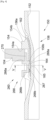
- FIG. 6 shows a sleeve fixing system 600 which is fixed to a beam 102 whose core 104 is pierced with a hole 106a and which receives two pipes 50a-b.
- the sleeve fixing system 600 comprises a cylinder 652, each end of which receives a pipe 50a-b by fitting and the cylinder 652 is fitted into the hole 106a of the beam 102.
- the sleeve fixing system 600 also comprises a flange 654 secured to the cylinder 652 and extending around the latter, where the flange 654 has a bearing face 654a which is opposite the beam 102 and a free face 654b to the opposite.
- the sleeve fixing system 600 also includes a holding system 660 comprising a washer 660a, in particular a flexible washer such as a Belleville washer, which is fitted onto the cylinder 652 and is positioned between the bearing face 654a and the beam 102 .
- a holding system 660 comprising a washer 660a, in particular a flexible washer such as a Belleville washer, which is fitted onto the cylinder 652 and is positioned between the bearing face 654a and the beam 102 .
- the sleeve fixing system 600 also comprises a plurality of links 664 where each has a first end secured to the washer 660a and a second free end opposite the washer 660a, where each link 664 takes the form of a collar self-locking clamp with teeth 665. Each link 664 extends outside along the wall of the cylinder 652. Each link 664 passes through the hole 106a.
- the sleeve fixing system 600 also includes a locking system 666 comprising a hooking means 666b which attaches to the teeth 665 from the second end of the link 664 and a bearing surface 666a which bears against the beam 102 on the other side relative to washer 660a.
- the hooking means 666b here takes the form of a ratchet which cooperates with the teeth 665.
Landscapes
- Engineering & Computer Science (AREA)
- General Engineering & Computer Science (AREA)
- Mechanical Engineering (AREA)
- Mutual Connection Of Rods And Tubes (AREA)
- Quick-Acting Or Multi-Walled Pipe Joints (AREA)
- Supports For Pipes And Cables (AREA)
- Forms Removed On Construction Sites Or Auxiliary Members Thereof (AREA)
- Pivots And Pivotal Connections (AREA)
- Clamps And Clips (AREA)
Abstract
Description
- La présente invention concerne un système de fixation à manchon permettant de fixer des canalisations à travers un support tel qu'une poutrelle, ainsi qu'un ensemble comportant une poutrelle, des canalisations et un tel système de fixation à manchon.
- Il existe de nombreux moyens pour fixer des canalisations. Par exemple, dans un aéronef, il existe des poutrelles horizontales et les canalisations, en particulier, les canalisations d'air conditionné, sont fixées aux poutrelles soit au-dessus ou au-dessous de celles-ci.
- Du fait du positionnement des canalisations, l'espace au-dessus et au-dessous des poutrelles est encombré, ce qui réduit l'habitabilité de l'aéronef.
- En outre, pour fixer les canalisations, il est souvent nécessaire de réaliser des perçages dans les poutrelles pour y fixer des ferrures auxquelles les canalisations sont attachées.
- Il est donc nécessaire de trouver un arrangement qui permette de limiter l'encombrement des canalisations et qui évite d'avoir à percer les poutrelles.
- Un objet de la présente invention est de proposer un système de fixation à manchon qui est arrangé pour être fixé à l'intérieur d'un trou traversant une poutrelle.
- À cet effet, est proposé un système de fixation à manchon destiné à être fixé à une poutrelle percée d'un trou et à recevoir deux canalisations, ledit système de fixation à manchon comportant
- un cylindre dont chaque extrémité est destinée à recevoir par emmanchement une canalisation, où la paroi dudit cylindre est creusée d'au moins un tunnel étanche par rapport à l'intérieur du cylindre, où le cylindre est destiné à être emmanché dans un trou de la poutrelle,
- une collerette solidaire du cylindre et s'étendant autour du cylindre, où chaque tunnel présente une première et une deuxième ouvertures qui débouchent sur l'extérieur de la paroi du cylindre et de part et d'autre de la collerette, où la collerette présente une face d'appui destinée à être en appui contre la poutrelle et une face libre à l'opposé, et
- pour chaque tunnel, un système de maintien comportant un lien, un sabot solidaire d'une première extrémité du lien et un système de verrouillage, où le lien est logé dans le tunnel de manière à ce que le sabot soit bloqué au niveau de la première ouverture qui est du côté de la face libre et à ce que la deuxième extrémité du lien sorte par la deuxième ouverture du côté de la face d'appui et où le système de verrouillage comporte un moyen d'accrochage qui s'accroche à la deuxième extrémité du lien et une surface d'appui destinée à venir en appui contre la poutrelle. Avec un tel arrangement, les canalisations passent à travers la poutrelle au niveau d'un trou déjà présent.
- Avantageusement, le cylindre porte une canalisation de dérivation qui est arrangée du côté de la première ouverture par rapport à la collerette et qui débouche à l'intérieur du cylindre. Avantageusement, le lien prend la forme d'un collier de serrage autobloquant avec des dents, et le moyen d'accrochage présente un cliquet anti-retour qui coopère avec les dents pour bloquer le retrait du lien.
- Avantageusement, le cliquet est monté sur un bras élastique du moyen d'accrochage. Avantageusement, le système de maintien comporte un support qui prolonge la surface d'appui vers la collerette et destiné à pénétrer dans le trou en passant entre le toit du tunnel et la surface du trou.
- L'invention propose également un ensemble comportant :
- une poutrelle traversée par un trou,
- deux canalisations, et
- un système de fixation à manchon selon l'une des variantes précédentes où le cylindre est emmanché dans le trou et la face d'appui de la collerette est en appui contre la poutrelle, où la surface d'appui est contre la poutrelle, et où une canalisation est emmanchée sur chaque extrémité du cylindre.
- Les caractéristiques de l'invention mentionnées ci-dessus, ainsi que d'autres, apparaîtront plus clairement à la lecture de la description suivante d'un exemple de réalisation, ladite description étant faite en relation avec les dessins joints, parmi lesquels :
- [
Fig. 1 ] montre une vue en perspective d'un ensemble selon un premier mode de réalisation de l'invention, - [
Fig. 2 ] montre une vue en perspective d'un système de fixation à manchon selon l'invention, - [
Fig. 3 ] montre une vue en coupe et en perspective de l'ensemble de laFig. 1 par le plan III de laFig. 1 , - [
Fig. 4 ] montre une vue en coupe d'un ensemble selon un deuxième mode de réalisation de l'invention, - [
Fig. 5 ] montre une vue en coupe selon la ligne V-V de laFig. 4 , et - [
Fig. 6 ] montre une vue en coupe d'un ensemble selon un mode de réalisation non revendiqué. - La
Fig. 1 montre un ensemble 100 qui comporte une poutrelle 102, ici une poutre de type IPE, mais tout autre type de poutrelles est envisageable. - La poutrelle 102 comporte une âme 104 qui est traversée par au moins un trou 106a-b. Ici, il y a un trou 106a de forme circulaire et un trou 106b de forme elliptique, mais toute forme de trou est possible.
- L'ensemble 100 comporte également un système de fixation à manchon 150 dont un mode de réalisation est représenté à la
Fig. 2 et qui est fixé à la poutrelle 102 et reçoit deux canalisations 50a-b dudit ensemble 100 qui sont représentées en coupe partielle et en traits fantômes sur laFig. 2 . - Le système de fixation à manchon 150 est constitué d'une collerette 154 et d'un cylindre 152 présentant un axe X. La collerette 154 est solidaire de la paroi du cylindre 152 et s'étend de manière coaxiale autour de ladite paroi du cylindre 152 de manière à former une nervure périphérique extérieure. La collerette 154 est à distance de chaque extrémité du cylindre 152 pour permettre l'emmanchement d'une canalisation 50a-b sur chacune desdites extrémités, c'est-à-dire de part et d'autre de la collerette 154.
- La paroi du cylindre 152 est creusée d'au moins un tunnel 156 qui présente une première et une deuxième ouvertures 156a-b qui débouchent sur l'extérieur de la paroi du cylindre 152 et de part et d'autre de la collerette 154. Dans le mode de réalisation de l'invention présenté ici, il y a trois tunnels 156 pour assurer un meilleur maintien du système de fixation à manchon 150 sur l'âme 104. Chaque tunnel 156 s'étend parallèlement à l'axe X.
- Dans le cas du transport de fluide à l'intérieur du cylindre 152, chaque tunnel 156 est étanche par rapport à l'intérieur du cylindre 152. Si l'épaisseur de la paroi du cylindre 152 est suffisante, chaque tunnel 156 est creusé dans ladite paroi du cylindre 152 et si l'épaisseur est insuffisante, un renfort 158 est prévu à l'intérieur de la paroi du cylindre 152 afin de délimiter de manière étanche chaque tunnel 156. La paroi du cylindre 152, chaque renfort 158 et le tunnel 156 associé sont réalisés classiquement par moulage d'une matière plastique.
- Pour chaque tunnel 156, le système de fixation à manchon 150 comporte un système de maintien 160, 260 dont différents modes de réalisation sont décrits ci-dessous et qui assure la fixation du cylindre 152 sur la poutrelle 102.
- Lors de la mise en place du système de fixation à manchon 150, une extrémité du cylindre 152 est emmanchée dans un trou 106a-b de l'âme 104 de la poutrelle 102 de manière à amener la collerette 154 contre la bordure du trou 106a-b et contre l'âme 104. Le diamètre de la collerette 154 est supérieur à la dimension intérieure du trou 106a-b pour pouvoir s'adosser à la poutrelle 102. La collerette 154 présente ainsi une face d'appui 154a (
Figs. 3 et4 ) qui est en appui contre la poutrelle 102 et une face libre 154b à l'opposé. - Comme cela est représenté sur les
Figs. 3 à 5 , le système de maintien 160, 260 comporte un lien 164 et un sabot 162 solidaire d'une première extrémité du lien 164. Le lien 164 est logé dans le tunnel 156 et présente une deuxième extrémité qui est à l'opposé du sabot 162 et qui est introduite dans le tunnel 156 par la première ouverture 156a qui est du côté de la face libre 154b de la collerette 154 pour ressortir par la deuxième ouverture 156b du côté de la face d'appui 154a. Les dimensions du sabot 162 et du tunnel 156 sont telles que le sabot 162 ne peut pas traverser le tunnel 156 et le sabot 162 est ainsi bloqué au niveau de la première ouverture 156a. Le lien 164 est de préférence souple pour faciliter le passage dans le tunnel 156 et sa deuxième extrémité sort par la deuxième ouverture 156b. - Le système de maintien 160, 260 comporte un système de verrouillage 166, 266 qui comporte une surface d'appui 166a, 266a qui, en utilisation, est en appui contre l'âme 104 de la poutrelle 102 à l'opposé de la face d'appui 154a par rapport à la poutrelle 102, et un moyen d'accrochage 166b, 266b qui s'accroche à la deuxième extrémité du lien 164 de manière à bloquer le lien 164 dans le tunnel 156 et ainsi éviter le retrait dudit lien 164 tout en assurant le serrage de la surface d'appui 166a, 266a contre l'âme 104.
- Lors de la mise en place, la deuxième extrémité du lien 164 est tirée de manière à bloquer le sabot 162 au niveau de la première ouverture 156a du tunnel 156, puis le système de verrouillage 166, 266 est déplacé le long du lien 164 de sa deuxième extrémité vers sa première extrémité de manière à amener la surface d'appui 166a, 266a contre la poutrelle 102 et ainsi réaliser un serrage de la poutrelle 102 entre la face d'appui 154a de la collerette 154 et la surface d'appui 166a, 266a du système de verrouillage 166, 266. Dans le même temps, le moyen d'accrochage 166b, 266b s'accroche à la deuxième extrémité du lien 164 pour bloquer le sabot 162 et la surface d'appui 166a, 266a.
- Chaque canalisation 50a-b est emmanchée de manière étanche sur une extrémité du cylindre 152. L'étanchéité est réalisée par tous moyens appropriés, comme par exemple la mise en place et le serrage d'un serre-joint circulaire autour de la canalisation 50a-b, en particulier dans le cas d'une canalisation50a-b souple, mais l'étanchéité peut également être réalisée par collage, ou la mise en place d'un joint entre le cylindre 152 et la canalisation 50a-b.
- Ainsi, le système de fixation à manchon 150 est logé dans un trou 106a-b de la poutrelle 102 et n'empiète plus sur l'espace disponible au-dessus ou au-dessous de ladite poutrelle 102.
- Dans le mode de réalisation de l'invention présenté à la
Fig. 2 , le cylindre 152 porte une canalisation de dérivation 202 qui est arrangée du côté de la première ouverture 156a par rapport à la collerette 154, c'est-à-dire du côté opposé à la face d'appui 154a et qui débouche à l'intérieur du cylindre 152 et permet de connecter fluidiquement une canalisation de dérivation. - La
Fig. 3 montre un mode de réalisation particulier du système de maintien 160. Dans ce mode de réalisation, le lien 164 prend la forme d'un collier de serrage autobloquant du type « Ty-Rap » ® par exemple. C'est-à-dire que le lien 164 présente des dents 165 et le moyen d'accrochage 166b présente une fente 168a dans laquelle est inséré le lien 164 et, à l'intérieur de la fente 168a, le moyen d'accrochage 166b présente un cliquet anti-retour 168b qui coopère avec les dents 165 pour bloquer le retrait du lien 164 dès qu'une dent 165 dudit lien 164 est en prise avec ledit cliquet 168b. Le lien 164 est ainsi pris en sandwich entre l'une des faces de la fente 168a et le cliquet 168b. - Selon un mode de réalisation particulier, le moyen d'accrochage 166b comporte un système de désengagement qui permet de désengager le cliquet 168b pour permettre de retirer le lien 164. Un tel système de désengagement est constitué par exemple d'un bras élastique sur lequel est monté le cliquet 168b et le basculement du bras permet alors d'éloigner le cliquet 168b des dents 165 du lien 164.
- La
Fig. 4 et laFig. 5 montrent un autre mode de réalisation particulier du système de maintien 260. Dans ce mode de réalisation, le lien 164 prend également la forme d'un collier de serrage autobloquant avec ses dents 165 et le moyen d'accrochage 266b présente un passage 268a sous lequel passe le lien 164 entre le toit dudit passage 268a et la paroi du cylindre 152. À la sortie du passage 268a, le moyen d'accrochage 266b comporte un cliquet anti-retour 268b qui coopère avec les dents 165 pour bloquer le retrait du lien 164 dès qu'une dent 165 dudit lien 164 est en prise avec ledit cliquet 268b. Le lien 164 est ainsi pris en sandwich entre la paroi du cylindre 152 et le cliquet 268b. - Dans ce mode de réalisation particulier, le moyen d'accrochage 266b comporte un système de désengagement qui permet de désengager le cliquet 268b pour permettre de retirer le lien 164. Un tel système de désengagement est constitué ici d'un bras élastique 267 du moyen d'accrochage 266b sur lequel est monté le cliquet 268b et le basculement du bras 267 permet alors d'éloigner le cliquet 268b des dents 165 du lien 164.
- Dans les modes de réalisation présentés à la
Fig. 3 , le diamètre du trou 106a-b de l'âme 104 est égal au diamètre du toit du tunnel 156, ce qui assure un bon positionnement du cylindre 152, mais le diamètre du trou 106a-b peut être plus grand comme cela est représenté à laFig. 4 . - Dans ce mode de réalisation, le système de maintien 260 comporte alors un support 270 qui prolonge la surface d'appui 266a vers la collerette 154 et pénètre dans le trou 106a-b de l'âme 104 en passant entre le toit du tunnel 156 et la surface du trou 106a-b. Le toit du tunnel 156 est la partie qui délimite le tunnel 156 et qui est orientée vers l'extérieur du cylindre 152.
- Le système de fixation à manchon 150 peut être préassemblé avant son utilisation par introduction du lien 164 dans le tunnel 156 et par mise en place du système de maintien 160, 260 sur le lien 164 dans une position non serrée. Le système de fixation à manchon 150 peut alors être mis en place dans le trou 106a-b de la poutrelle 102 et le système de maintien 160, 260 est actionné pour assurer le serrage.
- La
Fig. 6 montre un système de fixation à manchon 600 qui est fixé à une poutrelle 102 dont l'âme 104 est percée d'un trou 106a et qui reçoit deux canalisations 50a-b. Le système de fixation à manchon 600 comporte un cylindre 652 dont chaque extrémité reçoit par emmanchement une canalisation 50a-b et le cylindre 652 est emmanché dans le trou 106a de la poutrelle 102. - Le système de fixation à manchon 600 comporte également une collerette 654 solidaire du cylindre 652 et s'étendant autour de ce dernier, où la collerette 654 présente une face d'appui 654a qui est en regard de la poutrelle 102 et une face libre 654b à l'opposé.
- Le système de fixation à manchon 600 comporte également un système de maintien 660 comportant une rondelle 660a, en particulier une rondelle souple comme une rondelle Belleville, qui est emmanchée sur le cylindre 652 et se positionne entre la face d'appui 654a et la poutrelle 102.
- Le système de fixation à manchon 600 comporte également une pluralité de liens 664 où chacun présente une première extrémité solidaire de la rondelle 660a et une deuxième extrémité libre à l'opposé de la rondelle 660a, où chaque lien 664 prend la forme d'un collier de serrage autobloquant avec des dents 665. Chaque lien 664 s'étale à l'extérieur le long de la paroi du cylindre 652. Chaque lien 664 traverse le trou 106a.
- Le système de fixation à manchon 600 comporte également un système de verrouillage 666 comportant un moyen d'accrochage 666b qui s'accroche aux dents 665 à partir de la deuxième extrémité du lien 664 et une surface d'appui 666a qui vient en appui contre la poutrelle 102 de l'autre côté par rapport à la rondelle 660a. Le moyen d'accrochage 666b prend ici la forme d'un cliquet qui coopère avec les dents 665.
Claims (6)
- Système de fixation à manchon (150) destiné à être fixé à une poutrelle (102) percée d'un trou (106a-b) et à recevoir deux canalisations (50a-b), ledit système de fixation à manchon (150) comportant :- un cylindre (152) dont chaque extrémité est destinée à recevoir par emmanchement une canalisation (50a-b), où la paroi dudit cylindre (152) est creusée d'au moins un tunnel (156) étanche par rapport à l'intérieur du cylindre (152), où le cylindre (152) est destiné à être emmanché dans un trou (106a-b) de la poutrelle (102),- une collerette (154) solidaire du cylindre (152) et s'étendant autour du cylindre (152), où chaque tunnel (156) présente une première et une deuxième ouvertures (156a-b) qui débouchent sur l'extérieur de la paroi du cylindre (152) et de part et d'autre de la collerette (154), où la collerette (154) présente une face d'appui (154a) destinée à être en appui contre la poutrelle (102) et une face libre (154b) à l'opposé, et- pour chaque tunnel (156), un système de maintien (160, 260) comportant un lien (164), un sabot (162) solidaire d'une première extrémité du lien (164) et un système de verrouillage (166, 266), où le lien (164) est logé dans le tunnel (156) de manière à ce que le sabot (162) soit bloqué au niveau de la première ouverture (156a) qui est du côté de la face libre (154b) et à ce que la deuxième extrémité du lien (164) sorte par la deuxième ouverture (156b) du côté de la face d'appui (154a) et où le système de verrouillage (166, 266) comporte un moyen d'accrochage (166b, 266b) qui s'accroche à la deuxième extrémité du lien (164) et une surface d'appui (166a, 266a) destinée à venir en appui contre la poutrelle (102).
- Système de fixation à manchon (150) selon la revendication 1, caractérisé en ce que le cylindre (152) porte une canalisation de dérivation (202) qui est arrangée du côté de la première ouverture (156a) par rapport à la collerette (154) et qui débouche à l'intérieur du cylindre (152).
- Système de fixation à manchon (150) selon l'une des revendications 1 ou 2, caractérisé en ce que le lien (164) prend la forme d'un collier de serrage autobloquant avec des dents (165) et en ce que le moyen d'accrochage (166b, 266b) présente un cliquet anti-retour (168b, 268b) qui coopère avec les dents (165) pour bloquer le retrait du lien (164).
- Système de fixation à manchon (150) selon la revendication 3, caractérisé en ce que le cliquet (268b) est monté sur un bras élastique (267) du moyen d'accrochage (266b).
- Système de fixation à manchon (150) selon l'une des revendications 1 à 4, caractérisé en ce que le système de maintien (260) comporte un support (270) qui prolonge la surface d'appui (266a) vers la collerette (154) et destiné à pénétrer dans le trou (106a-b) en passant entre le toit du tunnel (156) et la surface du trou (106a-b).
- Ensemble (100) comportant :- une poutrelle (102) traversée par un trou (106a-b),- deux canalisations (50a-b), et- un système de fixation à manchon (150) selon l'une des revendications précédentes où le cylindre (152) est emmanché dans le trou (106a-b) et la face d'appui (154a) de la collerette (154) est en appui contre la poutrelle (102), où la surface d'appui (166a, 266a) est contre la poutrelle (102), et où une canalisation (50a-b) est emmanchée sur chaque extrémité du cylindre (152).
Applications Claiming Priority (1)
| Application Number | Priority Date | Filing Date | Title |
|---|---|---|---|
| FR2213534A FR3143708A1 (fr) | 2022-12-16 | 2022-12-16 | Système de fixation à manchon |
Publications (2)
| Publication Number | Publication Date |
|---|---|
| EP4386245A1 true EP4386245A1 (fr) | 2024-06-19 |
| EP4386245B1 EP4386245B1 (fr) | 2025-01-29 |
Family
ID=85937147
Family Applications (1)
| Application Number | Title | Priority Date | Filing Date |
|---|---|---|---|
| EP23215286.8A Active EP4386245B1 (fr) | 2022-12-16 | 2023-12-08 | Système de fixation à manchon |
Country Status (3)
| Country | Link |
|---|---|
| US (1) | US12565958B2 (fr) |
| EP (1) | EP4386245B1 (fr) |
| FR (1) | FR3143708A1 (fr) |
Citations (3)
| Publication number | Priority date | Publication date | Assignee | Title |
|---|---|---|---|---|
| EP1609637A1 (fr) * | 2004-06-21 | 2005-12-28 | J. Eberspächer GmbH & Co. KG | Tuyau de raccord pour un système de ventilation d'un véhicule |
| US20150010372A1 (en) * | 2013-07-08 | 2015-01-08 | Lockon Llc | Ratcheting fastener |
| US20210270392A1 (en) * | 2020-02-27 | 2021-09-02 | The Boeing Company | Apparatus and method for snap-fit clamping assembly |
Family Cites Families (8)
| Publication number | Priority date | Publication date | Assignee | Title |
|---|---|---|---|---|
| US1890006A (en) * | 1929-02-23 | 1932-12-06 | Taylor Instrument Co | Sanitary fitting for industrial thermometers |
| US3275347A (en) * | 1958-07-25 | 1966-09-27 | Gen Dynamics Corp | Coupling for conduits through bulkheads |
| US4225162A (en) * | 1978-09-20 | 1980-09-30 | Amp Incorporated | Liquid tight connector |
| DE60309311T2 (de) * | 2002-05-01 | 2007-05-31 | Mogens Vilhelmsen | Rohrabzweigung mit buchse mit einer keilförmigen nut und keil zum einführen in die buchse |
| US8474877B2 (en) * | 2007-09-19 | 2013-07-02 | Bridgeport Fittings, Inc. | Push-in fitting for electrical metallic tubing with enhanced sealing and continuity |
| TW201525248A (zh) * | 2013-10-23 | 2015-07-01 | Nichias Corp | 鋼樑之耐火被覆施工法及鋼樑之耐火被覆結構 |
| WO2015060388A1 (fr) * | 2013-10-23 | 2015-04-30 | ニチアス株式会社 | Structure à revêtement réfractaire pour des poutres en acier et matériau de manchette de pénétration pour un revêtement réfractaire |
| MX2019001822A (es) * | 2016-08-16 | 2019-08-01 | Dirk Johannes Van Den Berg Jan | Un dispositivo de sellado para sellar una fuga en una tuberia. |
-
2022
- 2022-12-16 FR FR2213534A patent/FR3143708A1/fr not_active Ceased
-
2023
- 2023-12-08 EP EP23215286.8A patent/EP4386245B1/fr active Active
- 2023-12-13 US US18/538,069 patent/US12565958B2/en active Active
Patent Citations (3)
| Publication number | Priority date | Publication date | Assignee | Title |
|---|---|---|---|---|
| EP1609637A1 (fr) * | 2004-06-21 | 2005-12-28 | J. Eberspächer GmbH & Co. KG | Tuyau de raccord pour un système de ventilation d'un véhicule |
| US20150010372A1 (en) * | 2013-07-08 | 2015-01-08 | Lockon Llc | Ratcheting fastener |
| US20210270392A1 (en) * | 2020-02-27 | 2021-09-02 | The Boeing Company | Apparatus and method for snap-fit clamping assembly |
Also Published As
| Publication number | Publication date |
|---|---|
| FR3143708A1 (fr) | 2024-06-21 |
| EP4386245B1 (fr) | 2025-01-29 |
| US20240200707A1 (en) | 2024-06-20 |
| US12565958B2 (en) | 2026-03-03 |
Similar Documents
| Publication | Publication Date | Title |
|---|---|---|
| EP0913613B1 (fr) | Manchon pour élément de tuyauterie | |
| EP1064489B1 (fr) | Raccord encliquetable pour tuyaux | |
| FR2788580A1 (fr) | Raccord pour tubes | |
| FR2554206A1 (fr) | Raccord a emboitement pour la connexion des extremites de deux tuyaux | |
| FR2588354A1 (fr) | Dispositif de raccordement d'un tuyau elastiquement deformable a un tube rigide | |
| FR2851634A1 (fr) | Pince de raccord et structure de raccordement de raccord destinees a verifier le raccordement complet entre un raccord et un tuyau | |
| FR2711761A1 (fr) | Dispositif de raccordement rapide. | |
| FR2863335A1 (fr) | Collier de serrage | |
| FR2683017A1 (fr) | Raccord pour tubes. | |
| EP4386245B1 (fr) | Système de fixation à manchon | |
| FR2920015A3 (fr) | Structure de vehicule automobile et procede de fixation d'un accessoire | |
| FR2707953A1 (fr) | Procédé pour coupler deux parties d'un boîtier, et boîtiers s'y rapportant, notamment pour installation de climatisation, chauffage et/ou ventilation d'automobile. | |
| FR2891889A1 (fr) | Embout de connexion etanche et piece terminale pour un tel embout | |
| EP0020213B1 (fr) | Raccord de branchement d'un drain sur un collecteur | |
| FR2662489A1 (fr) | Raccord de tuyaux pour rendre etanches des canalisations fuyantes. | |
| EP1925871B1 (fr) | Raccord de piquage, ensemble et assemblage correspondants | |
| EP1750047B1 (fr) | Support de pose pour des tuyaux, câbles, canalisations et autre circuits | |
| FR2496220A1 (fr) | Raccord a emboitement et son procede de montage | |
| FR2873800A1 (fr) | Echangeur de chaleur a assemblage mecanique et joint d'etancheite pour cet echangeur de chaleur | |
| EP4370818B1 (fr) | Dispositif de fixation d'un élément sur une partie d'un véhicule automobile | |
| EP4188756B1 (fr) | Attache pour fixation d'une conduite fluidique sur un bras | |
| FR2908710A1 (fr) | Dispositif de fixation d'un haut-parleur sur un panneau de vehicule | |
| EP0890775B1 (fr) | Dispositif de verrouillage pour un assemblage de deux éléments de canalisation, et assemblage d'éléments de canalisation en comportant application. | |
| FR2736976A1 (fr) | Attache pour goujon | |
| FR2785359A1 (fr) | Collier de prise en charge a bague anti-fluage de joint et procede de fabrication |
Legal Events
| Date | Code | Title | Description |
|---|---|---|---|
| PUAI | Public reference made under article 153(3) epc to a published international application that has entered the european phase |
Free format text: ORIGINAL CODE: 0009012 |
|
| STAA | Information on the status of an ep patent application or granted ep patent |
Free format text: STATUS: REQUEST FOR EXAMINATION WAS MADE |
|
| 17P | Request for examination filed |
Effective date: 20231208 |
|
| AK | Designated contracting states |
Kind code of ref document: A1 Designated state(s): AL AT BE BG CH CY CZ DE DK EE ES FI FR GB GR HR HU IE IS IT LI LT LU LV MC ME MK MT NL NO PL PT RO RS SE SI SK SM TR |
|
| GRAP | Despatch of communication of intention to grant a patent |
Free format text: ORIGINAL CODE: EPIDOSNIGR1 |
|
| STAA | Information on the status of an ep patent application or granted ep patent |
Free format text: STATUS: GRANT OF PATENT IS INTENDED |
|
| RIC1 | Information provided on ipc code assigned before grant |
Ipc: F16L 5/02 20060101ALN20241001BHEP Ipc: F16L 5/00 20060101AFI20241001BHEP |
|
| INTG | Intention to grant announced |
Effective date: 20241011 |
|
| GRAS | Grant fee paid |
Free format text: ORIGINAL CODE: EPIDOSNIGR3 |
|
| GRAA | (expected) grant |
Free format text: ORIGINAL CODE: 0009210 |
|
| STAA | Information on the status of an ep patent application or granted ep patent |
Free format text: STATUS: THE PATENT HAS BEEN GRANTED |
|
| AK | Designated contracting states |
Kind code of ref document: B1 Designated state(s): AL AT BE BG CH CY CZ DE DK EE ES FI FR GB GR HR HU IE IS IT LI LT LU LV MC ME MK MT NL NO PL PT RO RS SE SI SK SM TR |
|
| REG | Reference to a national code |
Ref country code: GB Ref legal event code: FG4D Free format text: NOT ENGLISH |
|
| REG | Reference to a national code |
Ref country code: CH Ref legal event code: EP |
|
| REG | Reference to a national code |
Ref country code: DE Ref legal event code: R096 Ref document number: 602023001919 Country of ref document: DE |
|
| REG | Reference to a national code |
Ref country code: IE Ref legal event code: FG4D Free format text: LANGUAGE OF EP DOCUMENT: FRENCH |
|
| REG | Reference to a national code |
Ref country code: NL Ref legal event code: MP Effective date: 20250129 |
|
| PG25 | Lapsed in a contracting state [announced via postgrant information from national office to epo] |
Ref country code: NL Free format text: LAPSE BECAUSE OF FAILURE TO SUBMIT A TRANSLATION OF THE DESCRIPTION OR TO PAY THE FEE WITHIN THE PRESCRIBED TIME-LIMIT Effective date: 20250129 |
|
| PG25 | Lapsed in a contracting state [announced via postgrant information from national office to epo] |
Ref country code: RS Free format text: LAPSE BECAUSE OF FAILURE TO SUBMIT A TRANSLATION OF THE DESCRIPTION OR TO PAY THE FEE WITHIN THE PRESCRIBED TIME-LIMIT Effective date: 20250429 |
|
| PG25 | Lapsed in a contracting state [announced via postgrant information from national office to epo] |
Ref country code: FI Free format text: LAPSE BECAUSE OF FAILURE TO SUBMIT A TRANSLATION OF THE DESCRIPTION OR TO PAY THE FEE WITHIN THE PRESCRIBED TIME-LIMIT Effective date: 20250129 |
|
| PG25 | Lapsed in a contracting state [announced via postgrant information from national office to epo] |
Ref country code: PL Free format text: LAPSE BECAUSE OF FAILURE TO SUBMIT A TRANSLATION OF THE DESCRIPTION OR TO PAY THE FEE WITHIN THE PRESCRIBED TIME-LIMIT Effective date: 20250129 |
|
| PG25 | Lapsed in a contracting state [announced via postgrant information from national office to epo] |
Ref country code: ES Free format text: LAPSE BECAUSE OF FAILURE TO SUBMIT A TRANSLATION OF THE DESCRIPTION OR TO PAY THE FEE WITHIN THE PRESCRIBED TIME-LIMIT Effective date: 20250129 |
|
| REG | Reference to a national code |
Ref country code: LT Ref legal event code: MG9D |
|
| PG25 | Lapsed in a contracting state [announced via postgrant information from national office to epo] |
Ref country code: IS Free format text: LAPSE BECAUSE OF FAILURE TO SUBMIT A TRANSLATION OF THE DESCRIPTION OR TO PAY THE FEE WITHIN THE PRESCRIBED TIME-LIMIT Effective date: 20250529 Ref country code: NO Free format text: LAPSE BECAUSE OF FAILURE TO SUBMIT A TRANSLATION OF THE DESCRIPTION OR TO PAY THE FEE WITHIN THE PRESCRIBED TIME-LIMIT Effective date: 20250429 |
|
| REG | Reference to a national code |
Ref country code: AT Ref legal event code: MK05 Ref document number: 1763738 Country of ref document: AT Kind code of ref document: T Effective date: 20250129 |
|
| PG25 | Lapsed in a contracting state [announced via postgrant information from national office to epo] |
Ref country code: HR Free format text: LAPSE BECAUSE OF FAILURE TO SUBMIT A TRANSLATION OF THE DESCRIPTION OR TO PAY THE FEE WITHIN THE PRESCRIBED TIME-LIMIT Effective date: 20250129 |
|
| PG25 | Lapsed in a contracting state [announced via postgrant information from national office to epo] |
Ref country code: PT Free format text: LAPSE BECAUSE OF FAILURE TO SUBMIT A TRANSLATION OF THE DESCRIPTION OR TO PAY THE FEE WITHIN THE PRESCRIBED TIME-LIMIT Effective date: 20250529 Ref country code: LV Free format text: LAPSE BECAUSE OF FAILURE TO SUBMIT A TRANSLATION OF THE DESCRIPTION OR TO PAY THE FEE WITHIN THE PRESCRIBED TIME-LIMIT Effective date: 20250129 |
|
| PG25 | Lapsed in a contracting state [announced via postgrant information from national office to epo] |
Ref country code: BG Free format text: LAPSE BECAUSE OF FAILURE TO SUBMIT A TRANSLATION OF THE DESCRIPTION OR TO PAY THE FEE WITHIN THE PRESCRIBED TIME-LIMIT Effective date: 20250129 Ref country code: GR Free format text: LAPSE BECAUSE OF FAILURE TO SUBMIT A TRANSLATION OF THE DESCRIPTION OR TO PAY THE FEE WITHIN THE PRESCRIBED TIME-LIMIT Effective date: 20250430 |
|
| PG25 | Lapsed in a contracting state [announced via postgrant information from national office to epo] |
Ref country code: AT Free format text: LAPSE BECAUSE OF FAILURE TO SUBMIT A TRANSLATION OF THE DESCRIPTION OR TO PAY THE FEE WITHIN THE PRESCRIBED TIME-LIMIT Effective date: 20250129 |
|
| PG25 | Lapsed in a contracting state [announced via postgrant information from national office to epo] |
Ref country code: SE Free format text: LAPSE BECAUSE OF FAILURE TO SUBMIT A TRANSLATION OF THE DESCRIPTION OR TO PAY THE FEE WITHIN THE PRESCRIBED TIME-LIMIT Effective date: 20250129 |
|
| PG25 | Lapsed in a contracting state [announced via postgrant information from national office to epo] |
Ref country code: SM Free format text: LAPSE BECAUSE OF FAILURE TO SUBMIT A TRANSLATION OF THE DESCRIPTION OR TO PAY THE FEE WITHIN THE PRESCRIBED TIME-LIMIT Effective date: 20250129 |
|
| PG25 | Lapsed in a contracting state [announced via postgrant information from national office to epo] |
Ref country code: DK Free format text: LAPSE BECAUSE OF FAILURE TO SUBMIT A TRANSLATION OF THE DESCRIPTION OR TO PAY THE FEE WITHIN THE PRESCRIBED TIME-LIMIT Effective date: 20250129 |
|
| PG25 | Lapsed in a contracting state [announced via postgrant information from national office to epo] |
Ref country code: IT Free format text: LAPSE BECAUSE OF FAILURE TO SUBMIT A TRANSLATION OF THE DESCRIPTION OR TO PAY THE FEE WITHIN THE PRESCRIBED TIME-LIMIT Effective date: 20250129 |
|
| PG25 | Lapsed in a contracting state [announced via postgrant information from national office to epo] |
Ref country code: EE Free format text: LAPSE BECAUSE OF FAILURE TO SUBMIT A TRANSLATION OF THE DESCRIPTION OR TO PAY THE FEE WITHIN THE PRESCRIBED TIME-LIMIT Effective date: 20250129 Ref country code: CZ Free format text: LAPSE BECAUSE OF FAILURE TO SUBMIT A TRANSLATION OF THE DESCRIPTION OR TO PAY THE FEE WITHIN THE PRESCRIBED TIME-LIMIT Effective date: 20250129 |
|
| PG25 | Lapsed in a contracting state [announced via postgrant information from national office to epo] |
Ref country code: RO Free format text: LAPSE BECAUSE OF FAILURE TO SUBMIT A TRANSLATION OF THE DESCRIPTION OR TO PAY THE FEE WITHIN THE PRESCRIBED TIME-LIMIT Effective date: 20250129 |
|
| PG25 | Lapsed in a contracting state [announced via postgrant information from national office to epo] |
Ref country code: SK Free format text: LAPSE BECAUSE OF FAILURE TO SUBMIT A TRANSLATION OF THE DESCRIPTION OR TO PAY THE FEE WITHIN THE PRESCRIBED TIME-LIMIT Effective date: 20250129 |
|
| REG | Reference to a national code |
Ref country code: DE Ref legal event code: R097 Ref document number: 602023001919 Country of ref document: DE |
|
| PLBE | No opposition filed within time limit |
Free format text: ORIGINAL CODE: 0009261 |
|
| STAA | Information on the status of an ep patent application or granted ep patent |
Free format text: STATUS: NO OPPOSITION FILED WITHIN TIME LIMIT |
|
| 26N | No opposition filed |
Effective date: 20251030 |
|
| PGFP | Annual fee paid to national office [announced via postgrant information from national office to epo] |
Ref country code: FR Payment date: 20251229 Year of fee payment: 3 |