EP4386239A1 - Temperature control system, vehicle, energy storage system, and multi-port valve - Google Patents
Temperature control system, vehicle, energy storage system, and multi-port valve Download PDFInfo
- Publication number
- EP4386239A1 EP4386239A1 EP23216907.8A EP23216907A EP4386239A1 EP 4386239 A1 EP4386239 A1 EP 4386239A1 EP 23216907 A EP23216907 A EP 23216907A EP 4386239 A1 EP4386239 A1 EP 4386239A1
- Authority
- EP
- European Patent Office
- Prior art keywords
- port
- separation
- valve
- valve core
- separation cavity
- Prior art date
- Legal status (The legal status is an assumption and is not a legal conclusion. Google has not performed a legal analysis and makes no representation as to the accuracy of the status listed.)
- Granted
Links
Images





Classifications
-
- B—PERFORMING OPERATIONS; TRANSPORTING
- B60—VEHICLES IN GENERAL
- B60K—ARRANGEMENT OR MOUNTING OF PROPULSION UNITS OR OF TRANSMISSIONS IN VEHICLES; ARRANGEMENT OR MOUNTING OF PLURAL DIVERSE PRIME-MOVERS IN VEHICLES; AUXILIARY DRIVES FOR VEHICLES; INSTRUMENTATION OR DASHBOARDS FOR VEHICLES; ARRANGEMENTS IN CONNECTION WITH COOLING, AIR INTAKE, GAS EXHAUST OR FUEL SUPPLY OF PROPULSION UNITS IN VEHICLES
- B60K11/00—Arrangement in connection with cooling of propulsion units
- B60K11/02—Arrangement in connection with cooling of propulsion units with liquid cooling
-
- F—MECHANICAL ENGINEERING; LIGHTING; HEATING; WEAPONS; BLASTING
- F16—ENGINEERING ELEMENTS AND UNITS; GENERAL MEASURES FOR PRODUCING AND MAINTAINING EFFECTIVE FUNCTIONING OF MACHINES OR INSTALLATIONS; THERMAL INSULATION IN GENERAL
- F16K—VALVES; TAPS; COCKS; ACTUATING-FLOATS; DEVICES FOR VENTING OR AERATING
- F16K11/00—Multiple-way valves, e.g. mixing valves; Pipe fittings incorporating such valves
- F16K11/02—Multiple-way valves, e.g. mixing valves; Pipe fittings incorporating such valves with all movable sealing faces moving as one unit
- F16K11/08—Multiple-way valves, e.g. mixing valves; Pipe fittings incorporating such valves with all movable sealing faces moving as one unit comprising only taps or cocks
- F16K11/085—Multiple-way valves, e.g. mixing valves; Pipe fittings incorporating such valves with all movable sealing faces moving as one unit comprising only taps or cocks with cylindrical plug
-
- B—PERFORMING OPERATIONS; TRANSPORTING
- B60—VEHICLES IN GENERAL
- B60H—ARRANGEMENTS OF HEATING, COOLING, VENTILATING OR OTHER AIR-TREATING DEVICES SPECIALLY ADAPTED FOR PASSENGER OR GOODS SPACES OF VEHICLES
- B60H1/00—Heating, cooling or ventilating devices
- B60H1/00271—HVAC devices specially adapted for particular vehicle parts or components and being connected to the vehicle HVAC unit
- B60H1/00278—HVAC devices specially adapted for particular vehicle parts or components and being connected to the vehicle HVAC unit for the battery
-
- B—PERFORMING OPERATIONS; TRANSPORTING
- B60—VEHICLES IN GENERAL
- B60H—ARRANGEMENTS OF HEATING, COOLING, VENTILATING OR OTHER AIR-TREATING DEVICES SPECIALLY ADAPTED FOR PASSENGER OR GOODS SPACES OF VEHICLES
- B60H1/00—Heating, cooling or ventilating devices
- B60H1/00357—Air-conditioning arrangements specially adapted for particular vehicles
- B60H1/00385—Air-conditioning arrangements specially adapted for particular vehicles for vehicles having an electrical drive, e.g. hybrid or fuel cell
- B60H1/00392—Air-conditioning arrangements specially adapted for particular vehicles for vehicles having an electrical drive, e.g. hybrid or fuel cell for electric vehicles having only electric drive means
-
- B—PERFORMING OPERATIONS; TRANSPORTING
- B60—VEHICLES IN GENERAL
- B60H—ARRANGEMENTS OF HEATING, COOLING, VENTILATING OR OTHER AIR-TREATING DEVICES SPECIALLY ADAPTED FOR PASSENGER OR GOODS SPACES OF VEHICLES
- B60H1/00—Heating, cooling or ventilating devices
- B60H1/00485—Valves for air-conditioning devices, e.g. thermostatic valves
-
- B—PERFORMING OPERATIONS; TRANSPORTING
- B60—VEHICLES IN GENERAL
- B60H—ARRANGEMENTS OF HEATING, COOLING, VENTILATING OR OTHER AIR-TREATING DEVICES SPECIALLY ADAPTED FOR PASSENGER OR GOODS SPACES OF VEHICLES
- B60H1/00—Heating, cooling or ventilating devices
- B60H1/00507—Details, e.g. mounting arrangements, desaeration devices
- B60H1/00557—Details of ducts or cables
- B60H1/00571—Details of ducts or cables of liquid ducts, e.g. for coolant liquids or refrigerants
-
- B—PERFORMING OPERATIONS; TRANSPORTING
- B60—VEHICLES IN GENERAL
- B60L—PROPULSION OF ELECTRICALLY-PROPELLED VEHICLES; SUPPLYING ELECTRIC POWER FOR AUXILIARY EQUIPMENT OF ELECTRICALLY-PROPELLED VEHICLES; ELECTRODYNAMIC BRAKE SYSTEMS FOR VEHICLES IN GENERAL; MAGNETIC SUSPENSION OR LEVITATION FOR VEHICLES; MONITORING OPERATING VARIABLES OF ELECTRICALLY-PROPELLED VEHICLES; ELECTRIC SAFETY DEVICES FOR ELECTRICALLY-PROPELLED VEHICLES
- B60L58/00—Methods or circuit arrangements for monitoring or controlling batteries or fuel cells, specially adapted for electric vehicles
- B60L58/10—Methods or circuit arrangements for monitoring or controlling batteries or fuel cells, specially adapted for electric vehicles for monitoring or controlling batteries
- B60L58/24—Methods or circuit arrangements for monitoring or controlling batteries or fuel cells, specially adapted for electric vehicles for monitoring or controlling batteries for controlling the temperature of batteries
-
- B—PERFORMING OPERATIONS; TRANSPORTING
- B60—VEHICLES IN GENERAL
- B60L—PROPULSION OF ELECTRICALLY-PROPELLED VEHICLES; SUPPLYING ELECTRIC POWER FOR AUXILIARY EQUIPMENT OF ELECTRICALLY-PROPELLED VEHICLES; ELECTRODYNAMIC BRAKE SYSTEMS FOR VEHICLES IN GENERAL; MAGNETIC SUSPENSION OR LEVITATION FOR VEHICLES; MONITORING OPERATING VARIABLES OF ELECTRICALLY-PROPELLED VEHICLES; ELECTRIC SAFETY DEVICES FOR ELECTRICALLY-PROPELLED VEHICLES
- B60L58/00—Methods or circuit arrangements for monitoring or controlling batteries or fuel cells, specially adapted for electric vehicles
- B60L58/10—Methods or circuit arrangements for monitoring or controlling batteries or fuel cells, specially adapted for electric vehicles for monitoring or controlling batteries
- B60L58/24—Methods or circuit arrangements for monitoring or controlling batteries or fuel cells, specially adapted for electric vehicles for monitoring or controlling batteries for controlling the temperature of batteries
- B60L58/26—Methods or circuit arrangements for monitoring or controlling batteries or fuel cells, specially adapted for electric vehicles for monitoring or controlling batteries for controlling the temperature of batteries by cooling
-
- B—PERFORMING OPERATIONS; TRANSPORTING
- B60—VEHICLES IN GENERAL
- B60L—PROPULSION OF ELECTRICALLY-PROPELLED VEHICLES; SUPPLYING ELECTRIC POWER FOR AUXILIARY EQUIPMENT OF ELECTRICALLY-PROPELLED VEHICLES; ELECTRODYNAMIC BRAKE SYSTEMS FOR VEHICLES IN GENERAL; MAGNETIC SUSPENSION OR LEVITATION FOR VEHICLES; MONITORING OPERATING VARIABLES OF ELECTRICALLY-PROPELLED VEHICLES; ELECTRIC SAFETY DEVICES FOR ELECTRICALLY-PROPELLED VEHICLES
- B60L58/00—Methods or circuit arrangements for monitoring or controlling batteries or fuel cells, specially adapted for electric vehicles
- B60L58/10—Methods or circuit arrangements for monitoring or controlling batteries or fuel cells, specially adapted for electric vehicles for monitoring or controlling batteries
- B60L58/24—Methods or circuit arrangements for monitoring or controlling batteries or fuel cells, specially adapted for electric vehicles for monitoring or controlling batteries for controlling the temperature of batteries
- B60L58/27—Methods or circuit arrangements for monitoring or controlling batteries or fuel cells, specially adapted for electric vehicles for monitoring or controlling batteries for controlling the temperature of batteries by heating
-
- F—MECHANICAL ENGINEERING; LIGHTING; HEATING; WEAPONS; BLASTING
- F16—ENGINEERING ELEMENTS AND UNITS; GENERAL MEASURES FOR PRODUCING AND MAINTAINING EFFECTIVE FUNCTIONING OF MACHINES OR INSTALLATIONS; THERMAL INSULATION IN GENERAL
- F16K—VALVES; TAPS; COCKS; ACTUATING-FLOATS; DEVICES FOR VENTING OR AERATING
- F16K11/00—Multiple-way valves, e.g. mixing valves; Pipe fittings incorporating such valves
- F16K11/02—Multiple-way valves, e.g. mixing valves; Pipe fittings incorporating such valves with all movable sealing faces moving as one unit
- F16K11/08—Multiple-way valves, e.g. mixing valves; Pipe fittings incorporating such valves with all movable sealing faces moving as one unit comprising only taps or cocks
- F16K11/085—Multiple-way valves, e.g. mixing valves; Pipe fittings incorporating such valves with all movable sealing faces moving as one unit comprising only taps or cocks with cylindrical plug
- F16K11/0856—Multiple-way valves, e.g. mixing valves; Pipe fittings incorporating such valves with all movable sealing faces moving as one unit comprising only taps or cocks with cylindrical plug having all the connecting conduits situated in more than one plane perpendicular to the axis of the plug
-
- F—MECHANICAL ENGINEERING; LIGHTING; HEATING; WEAPONS; BLASTING
- F16—ENGINEERING ELEMENTS AND UNITS; GENERAL MEASURES FOR PRODUCING AND MAINTAINING EFFECTIVE FUNCTIONING OF MACHINES OR INSTALLATIONS; THERMAL INSULATION IN GENERAL
- F16K—VALVES; TAPS; COCKS; ACTUATING-FLOATS; DEVICES FOR VENTING OR AERATING
- F16K27/00—Construction of housing; Use of materials therefor
- F16K27/06—Construction of housing; Use of materials therefor of taps or cocks
- F16K27/065—Construction of housing; Use of materials therefor of taps or cocks with cylindrical plugs
-
- Y—GENERAL TAGGING OF NEW TECHNOLOGICAL DEVELOPMENTS; GENERAL TAGGING OF CROSS-SECTIONAL TECHNOLOGIES SPANNING OVER SEVERAL SECTIONS OF THE IPC; TECHNICAL SUBJECTS COVERED BY FORMER USPC CROSS-REFERENCE ART COLLECTIONS [XRACs] AND DIGESTS
- Y02—TECHNOLOGIES OR APPLICATIONS FOR MITIGATION OR ADAPTATION AGAINST CLIMATE CHANGE
- Y02E—REDUCTION OF GREENHOUSE GAS [GHG] EMISSIONS, RELATED TO ENERGY GENERATION, TRANSMISSION OR DISTRIBUTION
- Y02E60/00—Enabling technologies; Technologies with a potential or indirect contribution to GHG emissions mitigation
- Y02E60/10—Energy storage using batteries
Definitions
- This application relates to the field of shunting system technologies, and specifically, to a temperature control system, a vehicle, an energy storage system, and a multi-port valve.
- a thermal management system With booming development of industries such as new energy vehicles, energy storage stations, and the like, importance and complexity of a thermal management system gradually increase. Especially, complexity of a liquid pipeline greatly increases.
- functional modules that may use a liquid pipeline include: battery cooling, battery heat pump heating, battery thermistor heating, load (power conversion system, PCS) cooling, energy storage cabinet dehumidification, and the like.
- PCS power conversion system
- motor cooling, passenger cabin cooling, heating, and the like are further involved.
- To implement temperature control at different positions of an entire device by using a thermal management system many electromagnetic three-port valves need to be disposed in a liquid cooling pipeline of the thermal management system. Use of a plurality of three-port valves may cause problems of complex control, complex installation, and high costs. In addition, relatively large space is occupied.
- This application provides a temperature control system, a vehicle, an energy storage system, and a multi-port valve, to help simplify a structure of the multi-port valve and reduce a volume of the multi-port valve.
- a simple structure of the multi-port valve also helps reduce a leakage risk of the temperature control system.
- this application provides a temperature control system, where the temperature control system includes a plurality of liquid pipelines and a multi-port valve.
- the multi-port valve includes a valve body and a valve core.
- the valve body has a mounting cavity, and the valve core is mounted in the mounting cavity.
- the valve body includes a body and a block-shaped additional portion, the mounting cavity is located on the body, and the block-shaped additional portion is attached to at least a part of a side wall of the body.
- the valve body includes a plurality of vias, and each via penetrates the block-shaped additional portion and a corresponding side wall of the body.
- Each liquid pipeline is configured to communicate with one via, there is a battery pack on at least one liquid pipeline, and the temperature control system is configured to control a temperature of the battery pack.
- a peripheral side of the valve core includes a plurality of separation cavities, at least two separation cavities are arranged in an axial direction of the valve core, and each separation cavity is configured to communicate with one or more vias.
- the temperature control system further includes a heat exchanger, there is the heat exchanger on at least one liquid pipeline, and the heat exchanger is further located on a heat exchange loop including a compressor.
- a temperature of liquid in the liquid pipeline is controlled by using the heat exchanger, to control the temperature of the battery pack by using the liquid pipeline.
- a plurality of first openings are provided on an inner side wall of the body, and the first opening is an inner port of the via.
- the plurality of separation cavities of the valve core include a first separation cavity, and the first separation cavity communicates with a plurality of inner ports arranged in a circumferential direction of the valve core. Specifically, the first separation cavity communicates with two or more inner ports arranged in the circumferential direction of the valve core.
- the plurality of separation cavities of the valve core include a second separation cavity, and the second separation cavity communicates with two inner ports arranged in the axial direction of the valve core.
- the second separation cavity communicates with two or more inner ports arranged in the axial direction of the valve core.
- the multi-port valve is an eight-port valve, for example, a three-phase eight-port valve.
- the valve body includes eight vias, eight inner ports are arranged into a matrix of two rows and four columns, and inner ports in each row are arranged in the circumferential direction of the valve core.
- the valve core In a working mode of the multi-port valve, the valve core includes four first separation cavities, and the four first separation cavities are arranged into a matrix of two rows and two columns. Each first separation cavity communicates with two inner ports arranged in the circumferential direction of the valve core, and each first separation cavity communicates with every two inner ports in the eight inner ports, so that every two inner ports communicate with each other through a first separation cavity.
- the valve core in another working mode of the multi-port valve, includes two first separation cavities and two second separation cavities, the two first separation cavities are arranged in the axial direction of the valve core, and the two second separation cavities are arranged in the circumferential direction of the valve core.
- Each first separation cavity communicates with the two inner ports arranged in the circumferential direction of the valve core, and each second separation cavity is arranged in the axial direction of the valve core.
- Each first separation cavity communicates with two inner ports in the eight inner ports, and the two inner ports are arranged in the circumferential direction of the valve core.
- Each second separation cavity communicates with two inner ports in the eight inner ports, and the two inner ports are arranged in the axial direction of the valve core.
- the multi-port valve is a ten-port valve, for example, a four-phase ten-port valve.
- the valve body of the multi-port valve includes ten vias, and inner ports that are of the ten vias and that are on the side wall of the body are respectively a first port, a second port, a third port, a fourth port, a fifth port, a sixth port, a seventh port, an eighth port, a ninth port, and a tenth port.
- the first port and the second port are sequentially arranged in a first direction
- the third port, the fourth port, and the fifth port are sequentially arranged in the first direction
- the sixth port and the seventh port are sequentially arranged in the first direction
- the eighth port, the ninth port, and the tenth port are sequentially arranged in the first direction
- two ends of the valve core in the axial direction are a first end and a second end
- the first direction is a direction in which the first end faces the second end.
- the first port, the fourth port, the seventh port, and the tenth port are sequentially arranged in the circumferential direction of the valve core.
- the plurality of separation cavities of the valve core may further include a third separation cavity and a fourth separation cavity.
- the third separation cavity is an L-shaped separation cavity
- the third separation cavity includes a first part and a second part
- the first part communicates with two inner ports arranged in the circumferential direction of the valve core
- the second part communicates with two inner ports arranged in the axial direction of the valve core.
- the third separation cavity communicates with three inner ports.
- the two inner ports communicating with the first part and the two inner ports communicating with the second part are completely different.
- the third separation cavity communicates with the four inner ports.
- the first port and the second port communicate with each other through a second separation cavity, and the second separation cavity communicates with two inner ports arranged in the axial direction of the valve core.
- the fourth port, the fifth port, and the seventh port communicate with each other through a third separation cavity, and the third separation cavity communicates with three inner ports.
- the third port and the sixth port communicate with each other through a first separation cavity, and the first separation cavity communicates with two inner ports arranged in the circumferential direction of the valve core.
- the eighth port, the ninth port, and the tenth port communicate with each other through another second separation cavity, and the another second separation cavity communicates with three inner ports arranged in the axial direction of the valve core.
- Each inner port is in a working state.
- the second port and the fifth port communicate with each other through a first separation cavity, and the first separation cavity communicates with two inner ports arranged in the circumferential direction of the valve core.
- the third port, the fourth port, and the seventh port communicate with each other through a third separation cavity, and the third separation cavity communicates with three inner ports.
- the eighth port, the ninth port, and the tenth port communicate with each other through a second separation cavity, and the second separation cavity communicates with three inner ports arranged in the axial direction of the valve core.
- the second port and the fifth port communicate with each other through a first separation cavity, and the first separation cavity communicates with two inner ports arranged in the circumferential direction of the valve core.
- the third port and the fourth port communicate with each other through a second separation cavity, and the second separation cavity communicates with two inner ports arranged in the axial direction of the valve core.
- the ninth port and the tenth port communicate with each other through another second separation cavity, and the second separation cavity communicates with two inner ports arranged in the axial direction of the valve core.
- the two second separation cavities each communicate with two inner ports arranged in the axial direction of the valve core.
- the first port and the fourth port communicate with each other through a first separation cavity, and the first separation cavity communicates with two inner ports arranged in the circumferential direction of the valve core.
- the second port and the fifth port communicate with each other through another first separation cavity, and the first separation cavity communicates with two inner ports arranged in the circumferential direction of the valve core.
- the seventh port and the tenth port communicate with each other through still another first separation cavity, and the first separation cavity communicates with two inner ports arranged in the circumferential direction of the valve core.
- the sixth port and the ninth port communicate with each other through yet another first separation cavity, and the first separation cavity communicates with two inner ports arranged in the circumferential direction of the valve core.
- the third port and the eighth port communicate with each other through a third separation cavity, and the third separation cavity can communicate with four inner ports and is configured to communicate with only two inner ports herein.
- the four working modes of the four-phase ten-port valve in the specific technical solution are as described above.
- the valve core may be driven to rotate by a specified angle relative to the valve body, to adjust the four working modes of the four-phase ten-port valve.
- the valve core may include a plurality of separation plates.
- the plurality of separation plates include a first separation plate and a second separation plate, the first separation plate is perpendicular to the axial direction of the valve core, the second separation plate is parallel to the axial direction of the valve core, and the plurality of separation plates form the plurality of separation cavities. Separation cavities of different properties may be formed when a separation plate is disposed or not disposed at each position based on a requirement.
- the via extends along a straight line, extends in a bending manner, or extends in a curving manner.
- a position relationship or a communication manner between an inner port and an outer port is not limited in this application.
- a layout of outer ports is not limited by a layout of inner ports. The layout of outer ports may be configured based on an actual application scenario, to simplify pipeline disposition of the temperature control system.
- each liquid pipeline communicates with one second opening.
- an opening that is of the via and that is on the block-shaped additional portion is an outer port, and a plurality of outer ports are located in a same plane. This helps communicate with an external liquid pipeline, and simplifies a layout manner of the liquid pipelines in the temperature control system.
- an opening that is of the via and that is on the body is an inner port, and two inner ports adjacent in a circumferential direction of the mounting cavity are spaced by a preset distance.
- the via is provided, so that the layout of inner ports may be not limited by the layout of outer ports, either, and a distance between the two inner ports adjacent in the circumferential direction may be relatively large. In this way, a requirement for precision of controlling a rotation angle of the valve core is relatively low, sealing between the valve body and the valve core is improved, and a leakage case of the multi-port valve is reduced.
- the body is a cylinder
- the block-shaped additional portion has a groove portion
- the groove portion accommodates at least a part of a side wall of the cylinder.
- the body and the block-shaped additional portion are of an integrally formed structure. This helps simplify the structure of the valve body and reduce a volume of the valve body.
- this application further provides a vehicle.
- the vehicle includes at least a battery pack and the temperature control system according to the first aspect.
- the temperature control system is configured to control a temperature of the battery pack. Mounting space reserved for the temperature control system in the vehicle is relatively small, and is not easily affected by liquid leakage.
- this application further provides an energy storage system.
- the energy storage system includes at least a battery pack and the temperature control system according to the first aspect.
- the temperature control system is configured to control a temperature of the battery pack. Mounting space reserved for the temperature control system in the energy storage system is relatively small, and is not easily affected by liquid leakage.
- this application provides a multi-port valve.
- the multi-port valve includes a valve body and a valve core.
- the valve body has a mounting cavity, and the valve core is mounted in the mounting cavity.
- the valve body includes a body and a block-shaped additional portion, the mounting cavity is located on the body, and the block-shaped additional portion is attached to at least a part of a side wall of the body.
- the valve body includes a plurality of vias, and each via penetrates the block-shaped additional portion and a corresponding side wall of the body.
- a peripheral side of the valve core includes a plurality of separation cavities, at least two separation cavities are arranged in an axial direction of the valve core, and each of at least one separation cavity is configured to communicate with one or more vias.
- a first opening is provided on an inner side wall of the body, and the first opening is an inner port of the via.
- the plurality of separation cavities of the valve core include a first separation cavity, and the first separation cavity communicates with a plurality of inner ports arranged in a circumferential direction of the valve core. This helps the multi-port valve adapt to distribution of liquid pipelines in the temperature control system, and communicate with the liquid pipelines in the temperature control system.
- a first opening is provided on an inner side wall of the body, and the first opening is an inner port of the via.
- the plurality of separation cavities of the valve core include a second separation cavity, and the second separation cavity communicates with a plurality of inner ports arranged in the axial direction of the valve core.
- the multi-port valve is an eight-port valve, for example, a three-phase eight-port valve.
- the valve body includes eight vias, eight inner ports are arranged into a matrix of two rows and four columns, and inner ports in each row are arranged in the circumferential direction of the valve core.
- the valve core In a working mode of the multi-port valve, the valve core includes four first separation cavities, and the four first separation cavities are arranged into a matrix of two rows and two columns. Each first separation cavity communicates with every two inner ports in the eight inner ports, so that every two inner ports communicate with each other through a first separation cavity.
- the valve core in another working mode of the multi-port valve, includes two first separation cavities and two second separation cavities, the two first separation cavities are arranged in the axial direction of the valve core, and the two second separation cavities are arranged in the circumferential direction of the valve core.
- Each first separation cavity communicates with two inner ports in the eight inner ports, and the two inner ports are arranged in the circumferential direction of the valve core.
- Each second separation cavity communicates with two inner ports in the eight inner ports, and the two inner ports are arranged in the axial direction of the valve core.
- the multi-port valve is a ten-port valve, for example, a four-phase ten-port valve.
- the valve body of the multi-port valve includes ten vias, and inner ports that are of the ten vias and that are on the side wall of the body are respectively a first port, a second port, a third port, a fourth port, a fifth port, a sixth port, a seventh port, an eighth port, a ninth port, and a tenth port.
- the first port and the second port are sequentially arranged in a first direction
- the third port, the fourth port, and the fifth port are sequentially arranged in the first direction
- the sixth port and the seventh port are sequentially arranged in the first direction
- the eighth port, the ninth port, and the tenth port are sequentially arranged in the first direction
- two ends of the valve core in the axial direction are a first end and a second end
- the first direction is a direction in which the first end faces the second end.
- the first port, the fourth port, the seventh port, and the tenth port are sequentially arranged in the circumferential direction of the valve core.
- the plurality of separation cavities of the valve core may further include a third separation cavity.
- the third separation cavity is an L-shaped separation cavity
- the third separation cavity includes a first part and a second part
- the first part communicates with two inner ports arranged in the circumferential direction of the valve core
- the second part communicates with two inner ports arranged in the axial direction of the valve core.
- the fourth separation cavity communicates with three inner ports arranged in the axial direction of the valve core.
- the third separation cavity communicates with three inner ports.
- the two inner ports communicating with the first part and the two inner ports communicating with the second part are completely different.
- the third separation cavity communicates with the four inner ports.
- the first port and the second port communicate with each other through a second separation cavity
- the fourth port, the fifth port, and the seventh port communicate with each other through a third separation cavity
- the third port and the sixth port communicate with each other through a first separation cavity
- the eighth port, the ninth port, and the tenth port communicate with each other through a fourth separation cavity.
- Each inner port is in a working state.
- the second port and the fifth port communicate with each other through a first separation cavity
- the third port, the fourth port, and the seventh port communicate with each other through a third separation cavity
- the eighth port, the ninth port, and the tenth port communicate with each other through a second separation cavity.
- the second port and the fifth port communicate with each other through a first separation cavity
- the third port and the fourth port communicate with each other through a second separation cavity
- the ninth port and the tenth port communicate with each other through another second separation cavity.
- the first port and the fourth port communicate with each other through a first separation cavity
- the second port and the fifth port communicate with each other through another first separation cavity
- the seventh port and the tenth port communicate with each other through still another first separation cavity
- the sixth port and the ninth port communicate with each other through yet another first separation cavity
- the third port and the eighth port communicate with each other through a third separation cavity.
- the four working modes of the four-phase ten-port valve in the specific technical solution are as described above.
- the valve core may be driven to rotate by a specified angle relative to the valve body, to adjust the four working modes of the four-phase ten-port valve.
- the valve core may include a plurality of separation plates.
- the plurality of separation plates include a first separation plate and a second separation plate, the first separation plate is perpendicular to the axial direction of the valve core, the second separation plate is parallel to the axial direction of the valve core, and the plurality of separation plates form the plurality of separation cavities. Separation cavities of different properties may be formed when a separation plate is disposed or not disposed at each position based on a requirement.
- the via extends along a straight line, extends in a bending manner, or extends in a curving manner.
- a position relationship or a communication manner between an inner port and an outer port is not limited in this application.
- a layout of outer ports is not limited by a layout of inner ports. The layout of outer ports may be configured based on an actual application scenario, to simplify pipeline disposition of the temperature control system.
- An opening that is of the via and that is on the block-shaped additional portion is an outer port, and a plurality of outer ports are located in a same plane. This helps communicate with an external liquid pipeline, and simplifies a layout manner of the liquid pipelines in the temperature control system.
- an opening that is of the via and that is on the body is an inner port, and two inner ports adjacent in a circumferential direction of the mounting cavity are spaced by a preset distance.
- the via is provided, so that the layout of inner ports may be not limited by the layout of outer ports, either, and a distance between the two inner ports adjacent in the circumferential direction may be relatively large. In this way, a requirement for precision of controlling a rotation angle of the valve core is relatively low, sealing between the valve body and the valve core is improved, and a leakage case of the multi-port valve is reduced.
- the body is a cylinder
- the block-shaped additional portion has a groove portion
- the groove portion accommodates at least a part of a side wall of the cylinder.
- the body and the block-shaped additional portion are of an integrally formed structure. This helps simplify the structure of the valve body and reduce a volume of the valve body.
- the temperature control system may be specifically a liquid cooling system, a heating system, a hydraulic system, or the like.
- the temperature control system includes a plurality of liquid pipelines. Liquid diversion, liquid confluence, and the like are involved between the plurality of liquid pipelines, and a pipeline in which liquid flowing needs to be adjusted.
- a temperature control system of the vehicle or a temperature control system of the energy storage system may use the temperature control system in embodiments of this application.
- the temperature control system of the vehicle may be configured to control a temperature of the temperature control system of the vehicle
- the temperature control system of the energy storage system may be configured to control a temperature of the temperature control system of the energy storage system.
- a valve group including a plurality of three-port valves may be disposed for implementation.
- a control process is relatively complex, a quantity of connected components is relatively large, and a leakage risk is relatively high.
- the valve group of the temperature control system has a large volume and occupies more space.
- FIG. 1(a) and FIG. 1(b) are a schematic diagram of two topologies of a temperature control system according to an embodiment of this application.
- the temperature control system includes a plurality of liquid pipelines and a multi-port valve 900.
- the liquid pipelines communicate with the multi-port valve.
- the temperature control system may dissipate heat for the battery pack or heat the battery pack based on an actual working environment, so that the battery pack works under an appropriate temperature condition.
- the heat exchanger is further located on a heat exchange loop 300 including a compressor.
- the temperature control system may be further configured to control a temperature of a load 200.
- the multi-port valve 900 in this embodiment is a ten-port valve.
- the temperature control system includes the heat exchange loop 300, a warming loop 400, a first cooling loop 500, a second cooling loop 600, a battery pack temperature control loop 700, and a load temperature control loop 800.
- the warming loop 400 and the first cooling loop 500 are both connected to the heat exchange loop 300 for heat exchange.
- the warming loop 400 exchanges heat with the heat exchange loop 300 by using a heat exchanger
- the first cooling loop 500 exchanges heat with the heat exchange loop 300 by using another heat exchanger.
- the battery pack temperature control loop 700 is connected to the battery pack 100 for heat conduction, and is configured to control the temperature of the battery pack 100.
- the load temperature control loop 800 is connected to the load 200 for heat conduction, and is configured to control the temperature of the load 200.
- the first cooling loop 500, the second cooling loop 600, the battery pack temperature control loop 700, and the load temperature control loop 800 are all connected to valve ports of the multi-port valve 900. In this way, the multi-port valve can be controlled based on an actual application scenario, so that different loops communicate with each other.
- the multi-port valve 900 is an eight-port valve. A difference between this embodiment and the embodiment shown in FIG. 1(a) lies only in that neither the load 200 nor the load temperature control loop 800 is included.
- the temperature control system may be a temperature control system of a vehicle.
- the vehicle includes at least a battery pack and the temperature control system, and the temperature control system is configured to control a temperature of the battery pack of the vehicle.
- the temperature control system may alternatively be a temperature control system of an energy storage system.
- the energy storage system includes a battery pack and the temperature control system, and the temperature control system is configured to control a temperature of the battery pack of the energy storage system.
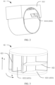
- FIG. 2 is a schematic diagram of a structure of a valve body of a multi-port valve according to an embodiment of this application.
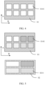
- FIG. 3 is a schematic diagram of a structure of a valve core of a multi-port valve according to an embodiment of this application.
- the valve body shown in FIG. 2 and the valve core shown in FIG. 3 are assembled to form a main body part of the multi-port valve in this embodiment of this application.
- the multi-port valve includes a valve body 01 and a valve core 02.
- the valve body 01 has a mounting cavity 011, and the valve core 02 is mounted in the mounting cavity 011.
- the valve body 01 includes a body 012 and a block-shaped additional portion 013.
- the body 012 and the block-shaped additional portion 013 are fastened to form the valve body 01.
- the mounting cavity 011 is located on the body 012.
- the valve body 01 includes a plurality of vias 014 communicating with the mounting cavity 011.
- each liquid pipeline is configured to communicate with one via.
- the block-shaped additional portion 013 is attached to at least a part of a side wall of the body 012, and each via 014 penetrates the block-shaped additional portion 013 and a corresponding side wall of the body 012.
- “configured to” indicates a capability of a structure, and is different from an actual connection relationship. For example, "A is configured for B” indicates that A has a related capability and can perform a function of B. However, actually, in a scenario or various scenarios, A may not implement the function of B.
- the body 012 is of a cylindrical structure.
- the block-shaped additional portion 013 is of a block structure including a groove portion
- the body 012 that is of a cylindrical structure is clamped into the groove portion of the block-shaped additional portion 013, and a part of the side wall of the body 012 is in contact with a concave surface of the groove portion of the block-shaped additional portion 013.
- an outer surface of the block-shaped additional portion 013 is a plane, and the outer surface of the block-shaped additional portion 013 is a surface that is of the block-shaped additional portion 013 and that is away from the groove portion.
- a peripheral side of the valve core 02 includes a plurality of separation cavities 021, at least two separation cavities 021 are arranged in an axial direction A of the valve core, and each separation cavity 021 is configured to communicate with one or more vias 014.
- a relative position relationship between the valve core 02 and the valve body 01 is adjusted, so that the separation cavity 021 can communicate with different vias 014, to change a communication relationship of a pipeline communicating with the multi-port valve.
- only one valve core 02 needs to be mounted in the valve body 01 of the multi-port valve, to implement adjustment in a mode of a liquid path communicating with the multi-port valve.
- This solution helps simplify a structure of the multi-port valve and reduce a volume of the multi-port valve.
- a simple structure of the multi-port valve also helps reduce a leakage risk of a temperature control system.
- a first opening that is of the via 014 and that is on the body 012 is an inner port 0141, or a first opening that is of the via 014 and that is on the side wall that is of the valve body 0 1 and that is on the periphery side of the mounting cavity 011 is an inner port 0141.
- the inner port 0141 is configured to communicate with the separation cavity 021 of the valve core 02.
- a second opening that is of the via 014 and that is on the block-shaped additional portion 013 is an outer port 0142, or a second opening that is of the via 014 and that is on a surface that is of the block-shaped additional portion 013 and that is away from the mounting cavity 011 is an outer port 0142.
- the outer port 0142 is configured to communicate with an external liquid pipeline, so that the multi-port valve is connected to the temperature control system.
- the inner port 0141 communicates with the outer port 0142 through the via 014.
- the block-shaped additional portion 013 has a preset volume, to enable the via 014 to have at least specific disposition space.
- the block-shaped additional portion 013 may not be specifically a square block. Selection may be performed based on an actual requirement. In other words, there is a preset distance between a surface of the mounting cavity 011 and the surface that is of the block-shaped additional portion 013 and on which the outer port 0142 is provided, to properly provide the via 014 based on a requirement.
- a position of the outer port 0142 may be specified based on a requirement. This facilitates communication between the multi-port valve and the pipeline, and helps improve pipeline communication regularity.
- the plurality of separation cavities 021 of the valve core 02 include a first separation cavity 021 1 and a second separation cavity 0212.
- the first separation cavity 0211 extends in a circumferential direction B of the valve core, so that the first separation cavity 0211 can communicate with a plurality of inner ports 0141 arranged in the circumferential direction B of the valve core.
- Adjacent first separation cavities 0211 are arranged in the axial direction A of the valve core.
- the second separation cavity 0212 can communicate with a plurality of inner ports 0141 arranged in the axial direction A of the valve core.
- Adjacent second separation cavities 0212 are arranged in the circumferential direction B of the valve core.
- the first separation cavity 0211 and the second separation cavity 0212 are properly provided, so that the inner ports 0141 arranged in the circumferential direction B of the valve core can communicate with each other, and the inner ports 0141 arranged in the axial direction A of the valve core can also communicate with each other.
- This helps the multi-port valve adapt to distribution of liquid pipelines in the temperature control system, and communicate with the liquid pipelines in the temperature control system.
- the separation cavity 021 of the valve core 02 communicates with at least two inner ports 0141.
- the separation cavity 021 may communicate with two inner ports 0141, or may communicate with three inner ports 0141, or may communicate with more inner ports 0141. This is not limited in this application. Selection may be performed based on an actual requirement.
- the valve core 02 may include a plurality of separation plates.
- the plurality of separation plates include a first separation plate 022 and a second separation plate 023.
- the first separation plate 022 is perpendicular to the axial direction A of the valve core
- the second separation plate 023 is parallel to the axial direction A of the valve core
- the plurality of separation plates form the plurality of separation cavities 021.
- the first separation plate 022 and the second separation plate 023 may be arranged based on a requirement, to form different layouts of the separation cavities 021, so as to implement the multi-port valve having different shunting manners.
- the mounting cavity 011 is a cylindrical mounting cavity 011
- the valve core 02 is a cylindrical valve core 02
- the valve core 02 and the mounting cavity 011 are mounted in a coaxial manner.
- the valve core 02 is mounted in the mounting cavity 011 of the valve body 01, and may circumferentially rotate in the mounting cavity 011.
- the multi-port valve may further include a driver.
- the driver is connected to the valve core 02, and is configured to drive the valve core 02 to rotate by a specified angle in the mounting cavity 011 of the valve body 01.
- the valve core 02 rotates to a specified position
- at least two inner ports 0141 communicate with one separation cavity 021, so that the inner ports 0141 communicating with the separation cavity 021 communicate with each other.
- the valve core 02 is controlled to rotate to different positions, so that different inner ports 0141 can communicate with each other, to change a communication solution of the multi-port valve.
- the body 012 and the block-shaped additional portion 013 may be of an integrally formed structure.
- the valve body 01 is a valve body 01 made of a plastic material
- the valve body 01 that is of the integrally formed structure may be prepared by using an injection molding process
- the valve body 01 is a valve body 01 made of a metal material
- the valve body 01 that is of the integrally formed structure may be prepared by using a casting process.
- the body 012 and the block-shaped additional portion 013 may alternatively be of a split structure, and the body 012 and the block-shaped additional portion 013 are fastened by using a soldering process or the like, to form the valve body 01.
- the via 014 between the inner port 0141 and the outer port 0142 may extend along a straight line, extend in a bending manner, or extend in a curving manner. This is not limited in this application. Specifically, the via 014 between the inner port 0141 and the outer port 0142 extends along a straight line. That the inner port 0141 and the outer port 0142 extend in a bending manner means that the via 014 is formed by a plurality of straight-line sub-vias 014 communicating with each other. Alternatively, the inner port 0141 and the outer port 0142 extend in a curving manner means that the via 014 extends along a curve.
- a position relationship or a communication manner between the inner port 0141 and the outer port 0142 is not limited in this application.
- a layout of outer ports 0142 is not limited by a layout of inner ports 0141. Therefore, the layout of outer ports 0142 may be configured based on an actual application scenario, to simplify pipeline disposition of the temperature control system.
- the plurality of outer ports 0142 may be located in a same plane. This helps communicate with an external liquid pipeline, and simplifies a layout manner of the liquid pipelines in the temperature control system.
- the via 014 is provided, so that the layout of inner ports 0141 may be not limited by the layout of outer ports 0142, either, and two inner ports 0141 adjacent in a circumferential direction of the mounting cavity 011 may be spaced by a preset distance.
- a distance between the two inner ports 0141 adjacent in the circumferential direction may be relatively large. In this way, a requirement for precision of controlling a rotation angle of the valve core 02 is relatively low, sealing between the valve body 0 1 and the valve core 02 is improved, and a leakage case of the multi-port valve is reduced.
- the body 012 is a cylinder, and the mounting cavity 011 is located inside the cylinder.
- An outline of the body 012 is consistent with a shape of the internal mounting cavity 011. This helps reduce a volume of the valve body 01.
- the block-shaped additional portion 013 has the groove portion, and the groove portion accommodates at least a part of a side wall of the cylinder.
- the outer surface of the block-shaped additional portion 013 is a plane. This helps improve overall shape regularity of the multi-port valve and enable the plurality of outer ports 0142 to be located on a same plane.
- the multi-port valve in this embodiment of this application is a three-phase eight-port valve.
- the valve body 01 of the multi-port valve includes eight vias 014.
- the valve body 01 includes eight inner ports 0141 and eight outer ports 0142 that communicate with each other in a one-to-one correspondence manner.
- the valve core 02 includes two layers of separation cavities 021 arranged in the axial direction A of the valve core.
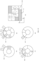
- FIG. 4 is a schematic diagram of expansion of the surface of the mounting cavity 011 of the valve body 0 1 according to an embodiment of this application.
- eight vias 014 are arranged into a matrix of two rows and four columns at an opening of the side wall of the body 012, that is, the eight inner ports 0141 are arranged into a matrix of two rows and four columns.
- four inner ports 0141 are arranged in a row in the circumferential direction of the mounting cavity 011, and the circumferential direction of the mounting cavity 011 may be specifically the circumferential direction B of the valve core.
- Two inner ports 0141 are arranged in a row in an axial direction of the mounting cavity 011, and the axial direction of the mounting cavity 011 may be specifically the axial direction A of the valve core.
- FIG. 5 is a schematic diagram of a correspondence between an inner port 0141 of the valve body 01 of the multi-port valve and a separation cavity 021 according to an embodiment of this application.
- a separation cavity 021 communicates with an inner port 0141 having a same filling pattern as the separation cavity 021.
- the valve core 02 includes four first separation cavities 0211, and the four first separation cavities 0211 are arranged into a matrix of two rows and two columns.
- Each first separation cavity 0211 communicates with every two inner ports 0141 in the eight inner ports 0141, so that every two inner ports 0141 communicate with each other through a first separation cavity 0211, and each inner port 0141 communicates with the first separation cavity 0211, to serve as a working status of the multi-port valve.
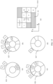
- FIG. 6 is a schematic diagram of another correspondence between an inner port 0141 of the valve body 01 of the multi-port valve and a separation cavity 021 according to an embodiment of this application.
- FIG. 7 is a schematic diagram of still another correspondence between an inner port 0141 of the valve body 01 of the multi-port valve and a separation cavity 021 according to an embodiment of this application.
- a separation cavity 021 communicates with an inner port 0141 having a same filling pattern as the separation cavity 021.
- the valve core 02 includes two first separation cavities 0211 and two second separation cavities 0212.
- the two first separation cavities 0211 are arranged in the axial direction A of the valve core, and the two second separation cavities 0212 are arranged in the circumferential direction B of the valve core.
- Each first separation cavity 0211 communicates with two inner ports 0141 in the eight inner ports 0141, and the two inner ports 0141 are arranged in the circumferential direction B of the valve core.
- Each second separation cavity 0212 communicates with two inner ports 0141 in the eight inner ports 0141, and the two inner ports 0141 are arranged in the axial direction A of the valve core.
- An arrangement relationship between the first separation cavity 0211 and the second separation cavity 0212 is not limited. For example, in the embodiment shown in FIG.
- the separation cavities 021 of the valve core 02 are sequentially the two second separation cavities 0212 and the two first separation cavities 0211.
- the separation cavities 021 of the valve core 02 are sequentially the two first separation cavities 0211 and the two second separation cavities 0212.
- FIG. 5 , FIG. 6, and FIG. 7 show three working modes of the three-phase eight-port valve in this embodiment of this application.
- the valve core 02 may be driven to rotate by a specified angle relative to the valve body 01, to adjust the three working modes of the three-phase eight-port valve.
- FIG. 8 is a schematic diagram of a structure of the valve body according to an embodiment of this application.
- FIG. 9 is a schematic diagram of a structure of the valve core according to an embodiment of this application.
- the multi-port valve in this embodiment is a four-phase ten-port valve.
- the valve body 01 includes the body 012 and the block-shaped additional portion 013 that are of an integrally formed structure.
- the body 012 is a cylinder, and the outer surface of the block-shaped additional portion 013 is a plane.
- the valve body 01 includes ten vias 014, and further includes ten inner ports 0141 and ten outer ports 0142 that communicate with each other in a one-to-one correspondence manner.
- the inner ports 0141 are located on a circumferential side wall of the mounting cavity 011, the outer ports 0142 are located on the surface that is of the block-shaped additional portion 013 and that is away from the mounting cavity 011, and the ten outer ports 0142 are located on a same plane.
- the inner port 0141 and the outer port 0142 communicate with each other through a straight-line via 014, and an extension direction of the straight-line via 014 is perpendicular to an axial direction of the mounting cavity 011.
- a preset distance between adjacent inner ports 0141 in the circumferential direction is relatively large. This helps improve sealing of the multi-port valve, and it is not easy to leak.
- the valve core 02 in this embodiment of this application is a cylindrical valve core, and the valve core 02 is mounted in the mounting cavity 011 of the valve body 01.
- the multi-port valve may further include a driver.
- the driver is connected to the valve body 01, and is configured to drive the valve core 02 to rotate by a specified angle in the mounting cavity 011 of the valve body 01.
- the valve core 02 includes a core portion, a plurality of first separation plates 022, and a plurality of second separation plates 023.
- the first separation plate 022 is perpendicular to the axial direction A of the valve core, and the first separation plate 022 extends in the circumferential direction B of the valve core.
- the first separation plate 022 does not necessarily extend in the circumferential direction B of the valve core to an entire circumference of the valve core 02, and may locally extend.
- the second separation plate 023 is parallel to the axial direction A of the valve core, and the second separation plate 023 extends in the axial direction A of the valve core.
- the second separation plate 023 only needs to connect two adjacent first separation plates 022.
- the plurality of first separation plates 022, the plurality of second separation plates 023, and the core portion fit to form the plurality of separation cavities 021.
- the separation cavity 021 of the multi-port valve may have a plurality of forms.
- the separation cavity 021 includes a first separation cavity 0211, a second separation cavity 0212, and a third separation cavity.
- the first separation cavity 0211 communicates with a plurality of inner ports 0141 arranged in the circumferential direction B of the valve core
- the second separation cavity 0212 can communicate with a plurality of inner ports 0141 arranged in the axial direction A of the valve core.
- Inner ports 0141 that communicate with a same separation cavity 021 communicate with each other.
- the third separation cavity is an L-shaped separation cavity, and the third separation cavity includes a first part and a second part. It may be considered that the first part and the second part are perpendicularly disposed.
- the first part extends in the circumferential direction B of the valve core. Specifically, the first part communicates with two inner ports 0141 arranged in the circumferential direction B of the valve core.
- the second part extends in the axial direction A of the valve core. Specifically, the second part communicates with two inner ports 0141 arranged in the axial direction A of the valve core.
- the third separation cavity communicates with three inner ports 0141.
- the two inner ports 0141 communicating with the first part and the two inner ports 0141 communicating with the second part are completely different. In other words, the third separation cavity communicates with the four inner ports 0141.
- the valve core 02 includes four layers of cavities arranged in the axial direction A of the valve core, and the four layers of cavities are sequentially a fourth layer of cavity 027, a third layer of cavity 026, a second layer of cavity 025, and a first layer of cavity 024 in the axial direction A of the valve core.
- FIG. 10 is a schematic diagram of expansion of a surface of the mounting cavity 011 of the valve body 01 according to an embodiment of this application.
- the valve body 01 includes ten vias 014, and inner ports 0141 that are of the ten vias 014 and that are on the side wall of the body 012 are respectively a first port 1, a second port 2, a third port 3, a fourth port 4, a fifth port 5, a sixth port 6, a seventh port 7, an eighth port 8, a ninth port 9, and a tenth port 10.
- the first port 1 and the second port 2 are sequentially arranged in a first direction X.
- the third port 3, the fourth port 4, and the fifth port 5 are sequentially arranged in the first direction X.
- the sixth port 6 and the seventh port 7 are sequentially arranged in the first direction X.
- the eighth port 8, the ninth port 9, and the tenth port 10 are sequentially arranged in the first direction X.
- Two ends of the valve body 01 in the axial direction of the mounting cavity 011 are a first end 015 and a second end 016, and the first direction X is a direction in which the first end 015 faces the second end 016.
- the first direction X extends in the axial direction of the mounting cavity 011, and has a fixed pointing direction.
- the first port 1, the fourth port 4, the seventh port 7, and the tenth port 10 are sequentially arranged in the circumferential direction B of the valve core.
- the openings are located at several point positions in a matrix of four rows and four columns.
- FIG. 11 is a schematic diagram of a working mode of the multi-port valve according to an embodiment of this application.
- (a), (b), (c), and (d) in FIG. 11 are respectively sectional views of the first layer of cavity 024, the second layer of cavity 025, the third layer of cavity 026, and the fourth layer of cavity 027.
- a part marked with a ring in the figure means that the part communicates with a part of a next layer of cavity at this position or a first separation plate 022 between the part and a next layer of cavity has an opening, to form a second separation cavity 0212 or a third separation cavity.
- (e) in FIG. 11 is a schematic diagram of communication of inner ports 0141 in the working mode. Inner ports 0141 marked by arrows in the figure communicate with each other through a separation cavity 021.
- the first port 1 and the second port 2 communicate with each other through a second separation cavity 0212, and the second separation cavity 0212 communicates with two inner ports 0141;
- the fourth port 4, the fifth port 5, and the seventh port 7 communicate with each other through a third separation cavity, and the third separation cavity communicates with three inner ports 0141;
- the third port 3 and the sixth port 6 communicate with each other through a first separation cavity 0211, and the first separation cavity 0211 communicates with two inner ports 0141;
- the eighth port 8, the ninth port 9, and the tenth port 10 communicate with each other through a second separation cavity 0212, and the second separation cavity 0212 communicates with three inner ports 0141.
- each inner port 0141 is in a working state.
- FIG. 12 is a schematic diagram of another working mode of the multi-port valve according to an embodiment of this application.
- (a), (b), (c), and (d) in FIG. 12 are respectively sectional views of the first layer of cavity 024, the second layer of cavity 025, the third layer of cavity 026, and the fourth layer of cavity 027.
- a part marked with a ring in the figure means that the part communicates with a part of a next layer of cavity at this position or a first separation plate 022 between the part and a next layer of cavity has an opening, to form a second separation cavity 0212 or a third separation cavity.
- (e) in FIG. 12 is a schematic diagram of communication of inner ports 0141 in the working mode. Inner ports 0141 marked by arrows in the figure communicate with each other through a separation cavity 021.
- the second port 2 and the fifth port 5 communicate with each other through a first separation cavity 0211, and the first separation cavity 0211 communicates with two inner ports 0141; the third port 3, the fourth port 4, and the seventh port 7 communicate with each other through a third separation cavity, and the third separation cavity communicates with three inner ports 0141; and the eighth port 8, the ninth port 9, and the tenth port 10 communicate with each other through a second separation cavity 0212, and the second separation cavity 0212 communicates with three inner ports 0141.
- neither the first port 1 nor the sixth port 6 communicates with any inner port 0141 through a separation cavity.
- the first port 1 and the sixth port 6 each may communicate with one separation cavity 021.
- the separation cavity 021 communicating with the first port 1 communicates with only the first port 1
- the separation cavity 021 communicating with the sixth port 6 communicates with only the sixth port 6.
- FIG. 13 is a schematic diagram of still another working mode of the multi-port valve according to an embodiment of this application.
- (a), (b), (c), and (d) in FIG. 13 are respectively sectional views of the first layer of cavity 024, the second layer of cavity 025, the third layer of cavity 026, and the fourth layer of cavity 027.
- a part marked with a ring in the figure means that the part communicates with a part of a next layer of cavity at this position or a first separation plate 022 between the part and a next layer of cavity has an opening, to form a second separation cavity 0212 or a third separation cavity.
- (e) in FIG. 13 is a schematic diagram of communication of inner ports 0141 in the working mode. Inner ports 0141 marked by arrows in the figure communicate with each other through a separation cavity 021.
- the second port 2 and the fifth port 5 communicate with each other through a first separation cavity 0211, and the first separation cavity 0211 communicates with two inner ports 0141; the third port 3 and the fourth port 4 communicate with each other through a second separation cavity 0212, and the second separation cavity 0212 communicates with two inner ports 0141; and the ninth port 9 and the tenth port 10 communicate with each other through another second separation cavity 0212, and the second separation cavity 0212 communicates with two inner ports 0141.
- none of the first port 1, the sixth port 6, and the seventh port 7 communicates with any inner port 0141 through a separation cavity 021.
- the first port 1, the sixth port 6, and the seventh port 7 each may communicate with only one separation cavity 021.
- the separation cavity 021 communicating with the first port 1 communicates with only the first port 1
- the separation cavity 021 communicating with the sixth port 6 communicates with only the sixth port 6, and the separation cavity 021 communicating with the seventh port 7 communicates with only the seventh port 7.
- FIG. 14 is a schematic diagram of yet another working mode of the multi-port valve according to an embodiment of this application.
- (a), (b), (c), and (d) in FIG. 14 are respectively sectional views of the first layer of cavity 024, the second layer of cavity 025, the third layer of cavity 026, and the fourth layer of cavity 027.
- a part marked with a ring in the figure means that the part communicates with a part of a next layer of cavity at this position or a first separation plate 022 between the part and a next layer of cavity has an opening, to form a second separation cavity 0212 or a third separation cavity.
- (e) in FIG. 14 is a schematic diagram of communication of inner ports 0141 in the working mode. Inner ports 0141 marked by arrows in the figure communicate with each other through a separation cavity 021.
- the first port 1 and the fourth port 4 communicate with each other through a first separation cavity 0211, and the first separation cavity 0211 communicates with two inner ports 0141;
- the second port 2 and the fifth port 5 communicate with each other through another first separation cavity 0211, and the first separation cavity 0211 communicates with two inner ports 0141;
- the seventh port 7 and the tenth port 10 communicate with each other through still another first separation cavity 0211, and the first separation cavity 0211 communicates with two inner ports 0141;
- the sixth port 6 and the ninth port 9 communicate with each other through yet another first separation cavity 0211, and the first separation cavity 0211 communicates with two inner ports 0141;
- the third port 3 and the eighth port 8 communicate with each other through a third separation cavity, and the third separation cavity communicates with two inner ports 0141.
- the third separation cavity can communicate with four inner ports and is configured to communicate with only two inner ports herein.
- each inner port 0141 is in a working state.
- FIG. 11 , FIG. 12 , FIG. 13 , and FIG. 14 show four working modes of the four-phase ten-port valve in this embodiment of this application.
- the valve core 02 may be driven to rotate by a specified angle relative to the valve body 01, to adjust the four working modes of the four-phase ten-port valve.
Landscapes
- Engineering & Computer Science (AREA)
- Mechanical Engineering (AREA)
- General Engineering & Computer Science (AREA)
- Thermal Sciences (AREA)
- Physics & Mathematics (AREA)
- Transportation (AREA)
- Life Sciences & Earth Sciences (AREA)
- Sustainable Energy (AREA)
- Sustainable Development (AREA)
- Power Engineering (AREA)
- Chemical & Material Sciences (AREA)
- Combustion & Propulsion (AREA)
- Multiple-Way Valves (AREA)
- Cooling, Air Intake And Gas Exhaust, And Fuel Tank Arrangements In Propulsion Units (AREA)
- Secondary Cells (AREA)
- Electric Propulsion And Braking For Vehicles (AREA)
Abstract

Description
- This application relates to the field of shunting system technologies, and specifically, to a temperature control system, a vehicle, an energy storage system, and a multi-port valve.
- With booming development of industries such as new energy vehicles, energy storage stations, and the like, importance and complexity of a thermal management system gradually increase. Especially, complexity of a liquid pipeline greatly increases. For example, in an energy storage system, functional modules that may use a liquid pipeline include: battery cooling, battery heat pump heating, battery thermistor heating, load (power conversion system, PCS) cooling, energy storage cabinet dehumidification, and the like. In an automobile field, motor cooling, passenger cabin cooling, heating, and the like are further involved. To implement temperature control at different positions of an entire device by using a thermal management system, many electromagnetic three-port valves need to be disposed in a liquid cooling pipeline of the thermal management system. Use of a plurality of three-port valves may cause problems of complex control, complex installation, and high costs. In addition, relatively large space is occupied.
- This application provides a temperature control system, a vehicle, an energy storage system, and a multi-port valve, to help simplify a structure of the multi-port valve and reduce a volume of the multi-port valve. A simple structure of the multi-port valve also helps reduce a leakage risk of the temperature control system.
- According to a first aspect, this application provides a temperature control system, where the temperature control system includes a plurality of liquid pipelines and a multi-port valve. The multi-port valve includes a valve body and a valve core. The valve body has a mounting cavity, and the valve core is mounted in the mounting cavity. The valve body includes a body and a block-shaped additional portion, the mounting cavity is located on the body, and the block-shaped additional portion is attached to at least a part of a side wall of the body. The valve body includes a plurality of vias, and each via penetrates the block-shaped additional portion and a corresponding side wall of the body. Each liquid pipeline is configured to communicate with one via, there is a battery pack on at least one liquid pipeline, and the temperature control system is configured to control a temperature of the battery pack. A peripheral side of the valve core includes a plurality of separation cavities, at least two separation cavities are arranged in an axial direction of the valve core, and each separation cavity is configured to communicate with one or more vias. This solution helps simplify a structure of the multi-port valve and reduce a volume of the multi-port valve. A simple structure of the multi-port valve also helps reduce a leakage risk of the temperature control system.
- In a further technical solution, the temperature control system further includes a heat exchanger, there is the heat exchanger on at least one liquid pipeline, and the heat exchanger is further located on a heat exchange loop including a compressor. In this solution, a temperature of liquid in the liquid pipeline is controlled by using the heat exchanger, to control the temperature of the battery pack by using the liquid pipeline.
- In a specific technical solution, a plurality of first openings are provided on an inner side wall of the body, and the first opening is an inner port of the via. The plurality of separation cavities of the valve core include a first separation cavity, and the first separation cavity communicates with a plurality of inner ports arranged in a circumferential direction of the valve core. Specifically, the first separation cavity communicates with two or more inner ports arranged in the circumferential direction of the valve core.
- In addition, when the plurality of first openings are provided on the inner side wall of the body, and the first opening is the inner port of the via, the plurality of separation cavities of the valve core include a second separation cavity, and the second separation cavity communicates with two inner ports arranged in the axial direction of the valve core. Specifically, the second separation cavity communicates with two or more inner ports arranged in the axial direction of the valve core. This helps the multi-port valve adapt to distribution of the liquid pipelines in the temperature control system, and communicate with the liquid pipelines in the temperature control system.
- In a specific technical solution, the multi-port valve is an eight-port valve, for example, a three-phase eight-port valve. In this technical solution, the valve body includes eight vias, eight inner ports are arranged into a matrix of two rows and four columns, and inner ports in each row are arranged in the circumferential direction of the valve core.
- In a working mode of the multi-port valve, the valve core includes four first separation cavities, and the four first separation cavities are arranged into a matrix of two rows and two columns. Each first separation cavity communicates with two inner ports arranged in the circumferential direction of the valve core, and each first separation cavity communicates with every two inner ports in the eight inner ports, so that every two inner ports communicate with each other through a first separation cavity.
- In another working mode of the multi-port valve, the valve core includes two first separation cavities and two second separation cavities, the two first separation cavities are arranged in the axial direction of the valve core, and the two second separation cavities are arranged in the circumferential direction of the valve core. Each first separation cavity communicates with the two inner ports arranged in the circumferential direction of the valve core, and each second separation cavity is arranged in the axial direction of the valve core. Each first separation cavity communicates with two inner ports in the eight inner ports, and the two inner ports are arranged in the circumferential direction of the valve core. Each second separation cavity communicates with two inner ports in the eight inner ports, and the two inner ports are arranged in the axial direction of the valve core.
- In another specific technical solution, the multi-port valve is a ten-port valve, for example, a four-phase ten-port valve. The valve body of the multi-port valve includes ten vias, and inner ports that are of the ten vias and that are on the side wall of the body are respectively a first port, a second port, a third port, a fourth port, a fifth port, a sixth port, a seventh port, an eighth port, a ninth port, and a tenth port. The first port and the second port are sequentially arranged in a first direction, the third port, the fourth port, and the fifth port are sequentially arranged in the first direction, the sixth port and the seventh port are sequentially arranged in the first direction, the eighth port, the ninth port, and the tenth port are sequentially arranged in the first direction, two ends of the valve core in the axial direction are a first end and a second end, and the first direction is a direction in which the first end faces the second end. The first port, the fourth port, the seventh port, and the tenth port are sequentially arranged in the circumferential direction of the valve core.
- When the valve core is specifically disposed, the plurality of separation cavities of the valve core may further include a third separation cavity and a fourth separation cavity. The third separation cavity is an L-shaped separation cavity, the third separation cavity includes a first part and a second part, the first part communicates with two inner ports arranged in the circumferential direction of the valve core, and the second part communicates with two inner ports arranged in the axial direction of the valve core. There may be an overlapping inner port in the two inner ports communicating with the first part and the two inner ports communicating with the second part. In other words, the third separation cavity communicates with three inner ports. Alternatively, the two inner ports communicating with the first part and the two inner ports communicating with the second part are completely different. In other words, the third separation cavity communicates with the four inner ports.
- In a working mode of the multi-port valve, the first port and the second port communicate with each other through a second separation cavity, and the second separation cavity communicates with two inner ports arranged in the axial direction of the valve core. The fourth port, the fifth port, and the seventh port communicate with each other through a third separation cavity, and the third separation cavity communicates with three inner ports. The third port and the sixth port communicate with each other through a first separation cavity, and the first separation cavity communicates with two inner ports arranged in the circumferential direction of the valve core. The eighth port, the ninth port, and the tenth port communicate with each other through another second separation cavity, and the another second separation cavity communicates with three inner ports arranged in the axial direction of the valve core. Each inner port is in a working state.
- In another working mode of the multi-port valve, the second port and the fifth port communicate with each other through a first separation cavity, and the first separation cavity communicates with two inner ports arranged in the circumferential direction of the valve core. The third port, the fourth port, and the seventh port communicate with each other through a third separation cavity, and the third separation cavity communicates with three inner ports. The eighth port, the ninth port, and the tenth port communicate with each other through a second separation cavity, and the second separation cavity communicates with three inner ports arranged in the axial direction of the valve core.
- In still another working mode of the multi-port valve, the second port and the fifth port communicate with each other through a first separation cavity, and the first separation cavity communicates with two inner ports arranged in the circumferential direction of the valve core. The third port and the fourth port communicate with each other through a second separation cavity, and the second separation cavity communicates with two inner ports arranged in the axial direction of the valve core. The ninth port and the tenth port communicate with each other through another second separation cavity, and the second separation cavity communicates with two inner ports arranged in the axial direction of the valve core. In this technical solution, the two second separation cavities each communicate with two inner ports arranged in the axial direction of the valve core.
- In yet another working mode of the multi-port valve, the first port and the fourth port communicate with each other through a first separation cavity, and the first separation cavity communicates with two inner ports arranged in the circumferential direction of the valve core. The second port and the fifth port communicate with each other through another first separation cavity, and the first separation cavity communicates with two inner ports arranged in the circumferential direction of the valve core. The seventh port and the tenth port communicate with each other through still another first separation cavity, and the first separation cavity communicates with two inner ports arranged in the circumferential direction of the valve core. The sixth port and the ninth port communicate with each other through yet another first separation cavity, and the first separation cavity communicates with two inner ports arranged in the circumferential direction of the valve core. The third port and the eighth port communicate with each other through a third separation cavity, and the third separation cavity can communicate with four inner ports and is configured to communicate with only two inner ports herein.
- The four working modes of the four-phase ten-port valve in the specific technical solution are as described above. Specifically, the valve core may be driven to rotate by a specified angle relative to the valve body, to adjust the four working modes of the four-phase ten-port valve.
- Specifically, when the separation cavities of the valve core are formed, the valve core may include a plurality of separation plates. The plurality of separation plates include a first separation plate and a second separation plate, the first separation plate is perpendicular to the axial direction of the valve core, the second separation plate is parallel to the axial direction of the valve core, and the plurality of separation plates form the plurality of separation cavities. Separation cavities of different properties may be formed when a separation plate is disposed or not disposed at each position based on a requirement.
- When the valve body is specifically formed, the via extends along a straight line, extends in a bending manner, or extends in a curving manner. A position relationship or a communication manner between an inner port and an outer port is not limited in this application. A layout of outer ports is not limited by a layout of inner ports. The layout of outer ports may be configured based on an actual application scenario, to simplify pipeline disposition of the temperature control system.
- There are a plurality of second openings on an outer surface of the block-shaped additional portion, the second opening is an outer port of the via, and each liquid pipeline communicates with one second opening.
- Specifically, an opening that is of the via and that is on the block-shaped additional portion is an outer port, and a plurality of outer ports are located in a same plane. This helps communicate with an external liquid pipeline, and simplifies a layout manner of the liquid pipelines in the temperature control system.
- In addition, an opening that is of the via and that is on the body is an inner port, and two inner ports adjacent in a circumferential direction of the mounting cavity are spaced by a preset distance. The via is provided, so that the layout of inner ports may be not limited by the layout of outer ports, either, and a distance between the two inner ports adjacent in the circumferential direction may be relatively large. In this way, a requirement for precision of controlling a rotation angle of the valve core is relatively low, sealing between the valve body and the valve core is improved, and a leakage case of the multi-port valve is reduced.
- In a specific technical solution, the body is a cylinder, the block-shaped additional portion has a groove portion, and the groove portion accommodates at least a part of a side wall of the cylinder.
- To simplify a structure of the valve body, the body and the block-shaped additional portion are of an integrally formed structure. This helps simplify the structure of the valve body and reduce a volume of the valve body.
- According to a second aspect, this application further provides a vehicle. The vehicle includes at least a battery pack and the temperature control system according to the first aspect. The temperature control system is configured to control a temperature of the battery pack. Mounting space reserved for the temperature control system in the vehicle is relatively small, and is not easily affected by liquid leakage.
- According to a third aspect, this application further provides an energy storage system. The energy storage system includes at least a battery pack and the temperature control system according to the first aspect. The temperature control system is configured to control a temperature of the battery pack. Mounting space reserved for the temperature control system in the energy storage system is relatively small, and is not easily affected by liquid leakage.
- According to a fourth aspect, this application provides a multi-port valve. The multi-port valve includes a valve body and a valve core. The valve body has a mounting cavity, and the valve core is mounted in the mounting cavity. The valve body includes a body and a block-shaped additional portion, the mounting cavity is located on the body, and the block-shaped additional portion is attached to at least a part of a side wall of the body. The valve body includes a plurality of vias, and each via penetrates the block-shaped additional portion and a corresponding side wall of the body. A peripheral side of the valve core includes a plurality of separation cavities, at least two separation cavities are arranged in an axial direction of the valve core, and each of at least one separation cavity is configured to communicate with one or more vias. This solution helps simplify a structure of the multi-port valve and reduce a volume of the multi-port valve. A simple structure of the multi-port valve also helps reduce a leakage risk of a temperature control system.
- In a specific technical solution, a first opening is provided on an inner side wall of the body, and the first opening is an inner port of the via. The plurality of separation cavities of the valve core include a first separation cavity, and the first separation cavity communicates with a plurality of inner ports arranged in a circumferential direction of the valve core. This helps the multi-port valve adapt to distribution of liquid pipelines in the temperature control system, and communicate with the liquid pipelines in the temperature control system.
- In another specific technical solution, a first opening is provided on an inner side wall of the body, and the first opening is an inner port of the via. The plurality of separation cavities of the valve core include a second separation cavity, and the second separation cavity communicates with a plurality of inner ports arranged in the axial direction of the valve core.
- In a specific technical solution, the multi-port valve is an eight-port valve, for example, a three-phase eight-port valve. In this technical solution, the valve body includes eight vias, eight inner ports are arranged into a matrix of two rows and four columns, and inner ports in each row are arranged in the circumferential direction of the valve core.
- In a working mode of the multi-port valve, the valve core includes four first separation cavities, and the four first separation cavities are arranged into a matrix of two rows and two columns. Each first separation cavity communicates with every two inner ports in the eight inner ports, so that every two inner ports communicate with each other through a first separation cavity.
- In another working mode of the multi-port valve, the valve core includes two first separation cavities and two second separation cavities, the two first separation cavities are arranged in the axial direction of the valve core, and the two second separation cavities are arranged in the circumferential direction of the valve core. Each first separation cavity communicates with two inner ports in the eight inner ports, and the two inner ports are arranged in the circumferential direction of the valve core. Each second separation cavity communicates with two inner ports in the eight inner ports, and the two inner ports are arranged in the axial direction of the valve core.
- In another specific technical solution, the multi-port valve is a ten-port valve, for example, a four-phase ten-port valve. The valve body of the multi-port valve includes ten vias, and inner ports that are of the ten vias and that are on the side wall of the body are respectively a first port, a second port, a third port, a fourth port, a fifth port, a sixth port, a seventh port, an eighth port, a ninth port, and a tenth port. The first port and the second port are sequentially arranged in a first direction, the third port, the fourth port, and the fifth port are sequentially arranged in the first direction, the sixth port and the seventh port are sequentially arranged in the first direction, the eighth port, the ninth port, and the tenth port are sequentially arranged in the first direction, two ends of the valve core in the axial direction are a first end and a second end, and the first direction is a direction in which the first end faces the second end. The first port, the fourth port, the seventh port, and the tenth port are sequentially arranged in the circumferential direction of the valve core.
- When the valve core is specifically disposed, the plurality of separation cavities of the valve core may further include a third separation cavity. The third separation cavity is an L-shaped separation cavity, the third separation cavity includes a first part and a second part, the first part communicates with two inner ports arranged in the circumferential direction of the valve core, and the second part communicates with two inner ports arranged in the axial direction of the valve core. The fourth separation cavity communicates with three inner ports arranged in the axial direction of the valve core. There may be an overlapping inner port in the two inner ports communicating with the first part and the two inner ports communicating with the second part. In other words, the third separation cavity communicates with three inner ports. Alternatively, the two inner ports communicating with the first part and the two inner ports communicating with the second part are completely different. In other words, the third separation cavity communicates with the four inner ports.
- In a working mode of the multi-port valve, the first port and the second port communicate with each other through a second separation cavity, the fourth port, the fifth port, and the seventh port communicate with each other through a third separation cavity, the third port and the sixth port communicate with each other through a first separation cavity, and the eighth port, the ninth port, and the tenth port communicate with each other through a fourth separation cavity. Each inner port is in a working state.
- In another working mode of the multi-port valve, the second port and the fifth port communicate with each other through a first separation cavity, the third port, the fourth port, and the seventh port communicate with each other through a third separation cavity, and the eighth port, the ninth port, and the tenth port communicate with each other through a second separation cavity.
- In still another working mode of the multi-port valve, the second port and the fifth port communicate with each other through a first separation cavity, the third port and the fourth port communicate with each other through a second separation cavity, and the ninth port and the tenth port communicate with each other through another second separation cavity.
- In yet another working mode of the multi-port valve, the first port and the fourth port communicate with each other through a first separation cavity, the second port and the fifth port communicate with each other through another first separation cavity, the seventh port and the tenth port communicate with each other through still another first separation cavity, the sixth port and the ninth port communicate with each other through yet another first separation cavity, and the third port and the eighth port communicate with each other through a third separation cavity.
- The four working modes of the four-phase ten-port valve in the specific technical solution are as described above. Specifically, the valve core may be driven to rotate by a specified angle relative to the valve body, to adjust the four working modes of the four-phase ten-port valve.
- Specifically, when the separation cavities of the valve core are formed, the valve core may include a plurality of separation plates. The plurality of separation plates include a first separation plate and a second separation plate, the first separation plate is perpendicular to the axial direction of the valve core, the second separation plate is parallel to the axial direction of the valve core, and the plurality of separation plates form the plurality of separation cavities. Separation cavities of different properties may be formed when a separation plate is disposed or not disposed at each position based on a requirement.
- When the valve body is specifically formed, the via extends along a straight line, extends in a bending manner, or extends in a curving manner. A position relationship or a communication manner between an inner port and an outer port is not limited in this application. A layout of outer ports is not limited by a layout of inner ports. The layout of outer ports may be configured based on an actual application scenario, to simplify pipeline disposition of the temperature control system.
- An opening that is of the via and that is on the block-shaped additional portion is an outer port, and a plurality of outer ports are located in a same plane. This helps communicate with an external liquid pipeline, and simplifies a layout manner of the liquid pipelines in the temperature control system.
- In addition, an opening that is of the via and that is on the body is an inner port, and two inner ports adjacent in a circumferential direction of the mounting cavity are spaced by a preset distance. The via is provided, so that the layout of inner ports may be not limited by the layout of outer ports, either, and a distance between the two inner ports adjacent in the circumferential direction may be relatively large. In this way, a requirement for precision of controlling a rotation angle of the valve core is relatively low, sealing between the valve body and the valve core is improved, and a leakage case of the multi-port valve is reduced.
- In a specific technical solution, the body is a cylinder, the block-shaped additional portion has a groove portion, and the groove portion accommodates at least a part of a side wall of the cylinder.
- To simplify a structure of the valve body, the body and the block-shaped additional portion are of an integrally formed structure. This helps simplify the structure of the valve body and reduce a volume of the valve body.
-
-
FIG. 1(a) andFIG. 1(b) are a schematic diagram of topologies of a temperature control system according to an embodiment of this application; -
FIG. 2 is a schematic diagram of a structure of a valve body of a multi-port valve according to an embodiment of this application; -
FIG. 3 is a schematic diagram of a structure of a valve core of a multi-port valve according to an embodiment of this application; -
FIG. 4 is a schematic diagram of expansion of a surface of a mounting cavity of a valve body according to an embodiment of this application; -
FIG. 5 is a schematic diagram of a correspondence between an inner port of a valve body of a multi-port valve and a separation cavity according to an embodiment of this application; -
FIG. 6 is a schematic diagram of another correspondence between an inner port of a valve body of a multi-port valve and a separation cavity according to an embodiment of this application; -
FIG. 7 is a schematic diagram of still another correspondence between an inner port of a valve body of a multi-port valve and a separation cavity according to an embodiment of this application; -
FIG. 8 is a schematic diagram of another structure of a valve body according to an embodiment of this application; -
FIG. 9 is a schematic diagram of another structure of a valve core according to an embodiment of this application; -
FIG. 10 is a schematic diagram of expansion of a surface of a mounting cavity of a valve body according to an embodiment of this application; -
FIG. 11 is a schematic diagram of a working mode of a multi-port valve according to an embodiment of this application; -
FIG. 12 is a schematic diagram of another working mode of a multi-port valve according to an embodiment of this application; -
FIG. 13 is a schematic diagram of still another working mode of a multi-port valve according to an embodiment of this application; and -
FIG. 14 is a schematic diagram of yet another working mode of a multi-port valve according to an embodiment of this application. -
- 100: battery pack; 200: load; 300: heat exchange loop; 400: warming loop;
- 500: first cooling loop; 600: second cooling loop; 700: battery pack temperature control loop;
- 800: load temperature control loop; 900: multi-port valve; 01: valve body; 011: mounting cavity; 012: body; 013: block-shaped additional portion; 014: via; 0141: inner port; 0142: outer port; 015: first end; 016: second end; 02: valve core; 021: separation cavity; 0211: first separation cavity; 0212: second separation cavity; 022: first separation plate; 023: second separation plate;
- 024: a first layer of cavity; 025: a second layer of cavity; 026: a third layer of cavity; 027: a fourth layer of cavity;
- A: axial direction of the valve core; B: circumferential direction of the valve core; X: first direction; 1: first port; 2: second port; 3: third port; 4: fourth port; 5: fifth port; 6: sixth port; 7: seventh port; 8: eighth port; 9: ninth port; 10: tenth port.
- To make the objectives, technical solutions, and advantages of this application clearer, the following further describes this application in detail with reference to the accompanying drawings. However, example implementations may be implemented in a plurality of forms and should not be construed as being limited to implementations described herein. On the contrary, these implementations are provided such that this application is more comprehensive and complete and fully conveys the concept of the example implementations to a person skilled in the art. Same reference numerals in the accompanying drawings denote same or similar structures. Therefore, repeated description thereof is omitted. Expressions of positions and directions in this application are described by using the accompanying drawings as an example. However, changes may also be made as required, and all the changes fall within the protection scope of this application. The accompanying drawings in this application are merely used to illustrate relative position relationships and do not represent an actual scale.
- Terms used in the following embodiments are merely intended to describe specific embodiments, but are not intended to limit this application. As used in the specification and appended claims of this application, singular expressions "one", "a", "the foregoing", "the", and "the one" are also intended to include expressions such as "one or more", unless the contrary is clearly indicated in the context. It should be further understood that in the following embodiments of this application, "at least one" and "one or more" mean one, two, or more.
- Reference to "an embodiment", "some embodiments", or the like described in this specification indicates that one or more embodiments of this application include a specific feature, structure, or characteristic described with reference to the embodiments. Therefore, statements such as "in an embodiment", "in some embodiments", "in some other embodiments", "in other embodiments", and the like that appear at different places in this specification do not necessarily mean reference to a same embodiment. Instead, the statements mean "one or more but not all of embodiments", unless otherwise specifically emphasized in another manner. The terms "include", "contain", "have", and their variants all mean "include but are not limited to", unless otherwise specifically emphasized in another manner.
- In addition, descriptions of "first", "second", "third", and the like in embodiments of this application are merely intended to distinguish between different specific structures, and the structures may have a same feature.
- It should be noted that specific details are set forth in the following description to provide a thorough understanding of this application. However, this application can be implemented in numerous other manners different from those described herein, and a person skilled in the art may make similar inferences without departing from the connotation of this application. Therefore, this application is not limited to specific implementations disclosed below. Example implementations of this application are subsequently described in this specification, but the description is intended to describe general principles of this application and is not intended to limit the scope of this application. The protection scope of this application is subject to the appended claims.
- To facilitate understanding of a temperature control system, a vehicle, an energy storage system, and a multi-port valve provided in embodiments of this application, the following describes application scenarios of the temperature control system, the vehicle, the energy storage system, and the multi-port valve. The temperature control system may be specifically a liquid cooling system, a heating system, a hydraulic system, or the like. In conclusion, the temperature control system includes a plurality of liquid pipelines. Liquid diversion, liquid confluence, and the like are involved between the plurality of liquid pipelines, and a pipeline in which liquid flowing needs to be adjusted. For example, a temperature control system of the vehicle or a temperature control system of the energy storage system may use the temperature control system in embodiments of this application. Specifically, the temperature control system of the vehicle may be configured to control a temperature of the temperature control system of the vehicle, and the temperature control system of the energy storage system may be configured to control a temperature of the temperature control system of the energy storage system. In the conventional technology, a valve group including a plurality of three-port valves may be disposed for implementation. However, according to this solution, a control process is relatively complex, a quantity of connected components is relatively large, and a leakage risk is relatively high. In addition, the valve group of the temperature control system has a large volume and occupies more space.
-
FIG. 1(a) andFIG. 1(b) are a schematic diagram of two topologies of a temperature control system according to an embodiment of this application. The temperature control system includes a plurality of liquid pipelines and amulti-port valve 900. The liquid pipelines communicate with the multi-port valve. There is abattery pack 100 on at least one liquid pipeline, and the temperature control system is configured to control a temperature of the battery pack. Specifically, the temperature control system may dissipate heat for the battery pack or heat the battery pack based on an actual working environment, so that the battery pack works under an appropriate temperature condition. - As shown in
FIG. 1(a) , in a specific embodiment, there is a heat exchanger on at least one liquid pipeline, and the heat exchanger is further located on aheat exchange loop 300 including a compressor. The temperature control system may be further configured to control a temperature of aload 200. Themulti-port valve 900 in this embodiment is a ten-port valve. The temperature control system includes theheat exchange loop 300, awarming loop 400, afirst cooling loop 500, asecond cooling loop 600, a battery packtemperature control loop 700, and a loadtemperature control loop 800. Thewarming loop 400 and thefirst cooling loop 500 are both connected to theheat exchange loop 300 for heat exchange. For example, thewarming loop 400 exchanges heat with theheat exchange loop 300 by using a heat exchanger, and thefirst cooling loop 500 exchanges heat with theheat exchange loop 300 by using another heat exchanger. The battery packtemperature control loop 700 is connected to thebattery pack 100 for heat conduction, and is configured to control the temperature of thebattery pack 100. The loadtemperature control loop 800 is connected to theload 200 for heat conduction, and is configured to control the temperature of theload 200. Thefirst cooling loop 500, thesecond cooling loop 600, the battery packtemperature control loop 700, and the loadtemperature control loop 800 are all connected to valve ports of themulti-port valve 900. In this way, the multi-port valve can be controlled based on an actual application scenario, so that different loops communicate with each other. - As shown in
FIG. 1(b) , in another specific embodiment, themulti-port valve 900 is an eight-port valve. A difference between this embodiment and the embodiment shown inFIG. 1(a) lies only in that neither theload 200 nor the loadtemperature control loop 800 is included. - The temperature control system may be a temperature control system of a vehicle. Specifically, the vehicle includes at least a battery pack and the temperature control system, and the temperature control system is configured to control a temperature of the battery pack of the vehicle. In addition, the temperature control system may alternatively be a temperature control system of an energy storage system. The energy storage system includes a battery pack and the temperature control system, and the temperature control system is configured to control a temperature of the battery pack of the energy storage system.
-
FIG. 2 is a schematic diagram of a structure of a valve body of a multi-port valve according to an embodiment of this application.FIG. 3 is a schematic diagram of a structure of a valve core of a multi-port valve according to an embodiment of this application. The valve body shown inFIG. 2 and the valve core shown inFIG. 3 are assembled to form a main body part of the multi-port valve in this embodiment of this application. As shown inFIG. 2 and FIG. 3 , in this embodiment of this application, the multi-port valve includes avalve body 01 and avalve core 02. Thevalve body 01 has a mountingcavity 011, and thevalve core 02 is mounted in the mountingcavity 011. Thevalve body 01 includes abody 012 and a block-shapedadditional portion 013. Thebody 012 and the block-shapedadditional portion 013 are fastened to form thevalve body 01. Specifically, the mountingcavity 011 is located on thebody 012. Thevalve body 01 includes a plurality ofvias 014 communicating with the mountingcavity 011. Specifically, each liquid pipeline is configured to communicate with one via. The block-shapedadditional portion 013 is attached to at least a part of a side wall of thebody 012, and each via 014 penetrates the block-shapedadditional portion 013 and a corresponding side wall of thebody 012. - In embodiments of this application, "configured to" indicates a capability of a structure, and is different from an actual connection relationship. For example, "A is configured for B" indicates that A has a related capability and can perform a function of B. However, actually, in a scenario or various scenarios, A may not implement the function of B.
- Optionally, as shown in
FIG. 2 , thebody 012 is of a cylindrical structure. - Optionally, as shown in
FIG. 2 , the block-shapedadditional portion 013 is of a block structure including a groove portion, thebody 012 that is of a cylindrical structure is clamped into the groove portion of the block-shapedadditional portion 013, and a part of the side wall of thebody 012 is in contact with a concave surface of the groove portion of the block-shapedadditional portion 013. - Optionally, as shown in
FIG. 2 , an outer surface of the block-shapedadditional portion 013 is a plane, and the outer surface of the block-shapedadditional portion 013 is a surface that is of the block-shapedadditional portion 013 and that is away from the groove portion. - A peripheral side of the
valve core 02 includes a plurality ofseparation cavities 021, at least twoseparation cavities 021 are arranged in an axial direction A of the valve core, and eachseparation cavity 021 is configured to communicate with one ormore vias 014. In this embodiment of this application, a relative position relationship between thevalve core 02 and thevalve body 01 is adjusted, so that theseparation cavity 021 can communicate withdifferent vias 014, to change a communication relationship of a pipeline communicating with the multi-port valve. Specifically, in this embodiment of this application, only onevalve core 02 needs to be mounted in thevalve body 01 of the multi-port valve, to implement adjustment in a mode of a liquid path communicating with the multi-port valve. This solution helps simplify a structure of the multi-port valve and reduce a volume of the multi-port valve. A simple structure of the multi-port valve also helps reduce a leakage risk of a temperature control system. - A first opening that is of the via 014 and that is on the body 012 (specifically, a first opening on an inner side wall of the body 012) is an
inner port 0141, or a first opening that is of the via 014 and that is on the side wall that is of the valve body 0 1 and that is on the periphery side of the mountingcavity 011 is aninner port 0141. Theinner port 0141 is configured to communicate with theseparation cavity 021 of thevalve core 02. A second opening that is of the via 014 and that is on the block-shaped additional portion 013 (specifically, a second opening on the outer surface of the block-shaped additional portion 013) is anouter port 0142, or a second opening that is of the via 014 and that is on a surface that is of the block-shapedadditional portion 013 and that is away from the mountingcavity 011 is anouter port 0142. Theouter port 0142 is configured to communicate with an external liquid pipeline, so that the multi-port valve is connected to the temperature control system. Theinner port 0141 communicates with theouter port 0142 through thevia 014. - The block-shaped
additional portion 013 has a preset volume, to enable the via 014 to have at least specific disposition space. In this case, the block-shapedadditional portion 013 may not be specifically a square block. Selection may be performed based on an actual requirement. In other words, there is a preset distance between a surface of the mountingcavity 011 and the surface that is of the block-shapedadditional portion 013 and on which theouter port 0142 is provided, to properly provide the via 014 based on a requirement. According to this solution, a position of theouter port 0142 may be specified based on a requirement. This facilitates communication between the multi-port valve and the pipeline, and helps improve pipeline communication regularity. - As shown in
FIG. 3 , the plurality ofseparation cavities 021 of thevalve core 02 include afirst separation cavity 021 1 and asecond separation cavity 0212. Thefirst separation cavity 0211 extends in a circumferential direction B of the valve core, so that thefirst separation cavity 0211 can communicate with a plurality ofinner ports 0141 arranged in the circumferential direction B of the valve core. Adjacentfirst separation cavities 0211 are arranged in the axial direction A of the valve core. Thesecond separation cavity 0212 can communicate with a plurality ofinner ports 0141 arranged in the axial direction A of the valve core. Adjacentsecond separation cavities 0212 are arranged in the circumferential direction B of the valve core. In this solution, thefirst separation cavity 0211 and thesecond separation cavity 0212 are properly provided, so that theinner ports 0141 arranged in the circumferential direction B of the valve core can communicate with each other, and theinner ports 0141 arranged in the axial direction A of the valve core can also communicate with each other. This helps the multi-port valve adapt to distribution of liquid pipelines in the temperature control system, and communicate with the liquid pipelines in the temperature control system. - In a specific embodiment, the
separation cavity 021 of thevalve core 02 communicates with at least twoinner ports 0141. Specifically, theseparation cavity 021 may communicate with twoinner ports 0141, or may communicate with threeinner ports 0141, or may communicate with moreinner ports 0141. This is not limited in this application. Selection may be performed based on an actual requirement. - Still refer to
FIG. 3 . To form the plurality ofseparation cavities 021 of thevalve core 02, thevalve core 02 may include a plurality of separation plates. The plurality of separation plates include afirst separation plate 022 and asecond separation plate 023. Thefirst separation plate 022 is perpendicular to the axial direction A of the valve core, thesecond separation plate 023 is parallel to the axial direction A of the valve core, and the plurality of separation plates form the plurality ofseparation cavities 021. In a specific embodiment, thefirst separation plate 022 and thesecond separation plate 023 may be arranged based on a requirement, to form different layouts of theseparation cavities 021, so as to implement the multi-port valve having different shunting manners. - In a specific embodiment, the mounting
cavity 011 is a cylindrical mountingcavity 011, thevalve core 02 is acylindrical valve core 02, and thevalve core 02 and the mountingcavity 011 are mounted in a coaxial manner. Thevalve core 02 is mounted in the mountingcavity 011 of thevalve body 01, and may circumferentially rotate in the mountingcavity 011. Specifically, the multi-port valve may further include a driver. The driver is connected to thevalve core 02, and is configured to drive thevalve core 02 to rotate by a specified angle in the mountingcavity 011 of thevalve body 01. When thevalve core 02 rotates to a specified position, at least twoinner ports 0141 communicate with oneseparation cavity 021, so that theinner ports 0141 communicating with theseparation cavity 021 communicate with each other. Thevalve core 02 is controlled to rotate to different positions, so that differentinner ports 0141 can communicate with each other, to change a communication solution of the multi-port valve. - In a specific embodiment, the
body 012 and the block-shapedadditional portion 013 may be of an integrally formed structure. For example, if thevalve body 01 is avalve body 01 made of a plastic material, thevalve body 01 that is of the integrally formed structure may be prepared by using an injection molding process; or if thevalve body 01 is avalve body 01 made of a metal material, thevalve body 01 that is of the integrally formed structure may be prepared by using a casting process. - In another specific embodiment, the
body 012 and the block-shapedadditional portion 013 may alternatively be of a split structure, and thebody 012 and the block-shapedadditional portion 013 are fastened by using a soldering process or the like, to form thevalve body 01. - The via 014 between the
inner port 0141 and theouter port 0142 may extend along a straight line, extend in a bending manner, or extend in a curving manner. This is not limited in this application. Specifically, the via 014 between theinner port 0141 and theouter port 0142 extends along a straight line. That theinner port 0141 and theouter port 0142 extend in a bending manner means that the via 014 is formed by a plurality of straight-line sub-vias 014 communicating with each other. Alternatively, theinner port 0141 and theouter port 0142 extend in a curving manner means that the via 014 extends along a curve. - In conclusion, a position relationship or a communication manner between the
inner port 0141 and theouter port 0142 is not limited in this application. A layout ofouter ports 0142 is not limited by a layout ofinner ports 0141. Therefore, the layout ofouter ports 0142 may be configured based on an actual application scenario, to simplify pipeline disposition of the temperature control system. - Specifically, the plurality of
outer ports 0142 may be located in a same plane. This helps communicate with an external liquid pipeline, and simplifies a layout manner of the liquid pipelines in the temperature control system. - In addition, the via 014 is provided, so that the layout of
inner ports 0141 may be not limited by the layout ofouter ports 0142, either, and twoinner ports 0141 adjacent in a circumferential direction of the mountingcavity 011 may be spaced by a preset distance. In this solution, a distance between the twoinner ports 0141 adjacent in the circumferential direction may be relatively large. In this way, a requirement for precision of controlling a rotation angle of thevalve core 02 is relatively low, sealing between the valve body 0 1 and thevalve core 02 is improved, and a leakage case of the multi-port valve is reduced. - As shown in
FIG. 2 and FIG. 3 , in a specific embodiment, thebody 012 is a cylinder, and the mountingcavity 011 is located inside the cylinder. An outline of thebody 012 is consistent with a shape of the internal mountingcavity 011. This helps reduce a volume of thevalve body 01. In addition, the block-shapedadditional portion 013 has the groove portion, and the groove portion accommodates at least a part of a side wall of the cylinder. The outer surface of the block-shapedadditional portion 013 is a plane. This helps improve overall shape regularity of the multi-port valve and enable the plurality ofouter ports 0142 to be located on a same plane. - As shown in
FIG. 2 and FIG. 3 , in a specific embodiment, the multi-port valve in this embodiment of this application is a three-phase eight-port valve. Thevalve body 01 of the multi-port valve includes eightvias 014. Correspondingly, thevalve body 01 includes eightinner ports 0141 and eightouter ports 0142 that communicate with each other in a one-to-one correspondence manner. Thevalve core 02 includes two layers ofseparation cavities 021 arranged in the axial direction A of the valve core. -
FIG. 4 is a schematic diagram of expansion of the surface of the mountingcavity 011 of the valve body 0 1 according to an embodiment of this application. As shown inFIG. 4 , in this embodiment, eightvias 014 are arranged into a matrix of two rows and four columns at an opening of the side wall of thebody 012, that is, the eightinner ports 0141 are arranged into a matrix of two rows and four columns. In a specific embodiment, fourinner ports 0141 are arranged in a row in the circumferential direction of the mountingcavity 011, and the circumferential direction of the mountingcavity 011 may be specifically the circumferential direction B of the valve core. Twoinner ports 0141 are arranged in a row in an axial direction of the mountingcavity 011, and the axial direction of the mountingcavity 011 may be specifically the axial direction A of the valve core. -
FIG. 5 is a schematic diagram of a correspondence between aninner port 0141 of thevalve body 01 of the multi-port valve and aseparation cavity 021 according to an embodiment of this application. In the figure, aseparation cavity 021 communicates with aninner port 0141 having a same filling pattern as theseparation cavity 021. As shown inFIG. 5 , in an embodiment, thevalve core 02 includes fourfirst separation cavities 0211, and the fourfirst separation cavities 0211 are arranged into a matrix of two rows and two columns. Eachfirst separation cavity 0211 communicates with every twoinner ports 0141 in the eightinner ports 0141, so that every twoinner ports 0141 communicate with each other through afirst separation cavity 0211, and eachinner port 0141 communicates with thefirst separation cavity 0211, to serve as a working status of the multi-port valve. -
FIG. 6 is a schematic diagram of another correspondence between aninner port 0141 of thevalve body 01 of the multi-port valve and aseparation cavity 021 according to an embodiment of this application.FIG. 7 is a schematic diagram of still another correspondence between aninner port 0141 of thevalve body 01 of the multi-port valve and aseparation cavity 021 according to an embodiment of this application. In the figure, aseparation cavity 021 communicates with aninner port 0141 having a same filling pattern as theseparation cavity 021. As shown inFIG. 6 and FIG. 7 , in another embodiment, thevalve core 02 includes twofirst separation cavities 0211 and twosecond separation cavities 0212. The twofirst separation cavities 0211 are arranged in the axial direction A of the valve core, and the twosecond separation cavities 0212 are arranged in the circumferential direction B of the valve core. Eachfirst separation cavity 0211 communicates with twoinner ports 0141 in the eightinner ports 0141, and the twoinner ports 0141 are arranged in the circumferential direction B of the valve core. Eachsecond separation cavity 0212 communicates with twoinner ports 0141 in the eightinner ports 0141, and the twoinner ports 0141 are arranged in the axial direction A of the valve core. An arrangement relationship between thefirst separation cavity 0211 and thesecond separation cavity 0212 is not limited. For example, in the embodiment shown inFIG. 6 , theseparation cavities 021 of thevalve core 02 are sequentially the twosecond separation cavities 0212 and the twofirst separation cavities 0211. In the embodiment shown inFIG. 7 , theseparation cavities 021 of thevalve core 02 are sequentially the twofirst separation cavities 0211 and the twosecond separation cavities 0212. - In a specific embodiment,
FIG. 5 ,FIG. 6, and FIG. 7 show three working modes of the three-phase eight-port valve in this embodiment of this application. Specifically, thevalve core 02 may be driven to rotate by a specified angle relative to thevalve body 01, to adjust the three working modes of the three-phase eight-port valve. -
FIG. 8 is a schematic diagram of a structure of the valve body according to an embodiment of this application.FIG. 9 is a schematic diagram of a structure of the valve core according to an embodiment of this application. As shown inFIG. 8 and FIG. 9 , the multi-port valve in this embodiment is a four-phase ten-port valve. In this embodiment, thevalve body 01 includes thebody 012 and the block-shapedadditional portion 013 that are of an integrally formed structure. Thebody 012 is a cylinder, and the outer surface of the block-shapedadditional portion 013 is a plane. Thevalve body 01 includes tenvias 014, and further includes teninner ports 0141 and tenouter ports 0142 that communicate with each other in a one-to-one correspondence manner. Theinner ports 0141 are located on a circumferential side wall of the mountingcavity 011, theouter ports 0142 are located on the surface that is of the block-shapedadditional portion 013 and that is away from the mountingcavity 011, and the tenouter ports 0142 are located on a same plane. In addition, as shown inFIG. 8 , theinner port 0141 and theouter port 0142 communicate with each other through a straight-line via 014, and an extension direction of the straight-line via 014 is perpendicular to an axial direction of the mountingcavity 011. A preset distance between adjacentinner ports 0141 in the circumferential direction is relatively large. This helps improve sealing of the multi-port valve, and it is not easy to leak. - As shown in
FIG. 9 , thevalve core 02 in this embodiment of this application is a cylindrical valve core, and thevalve core 02 is mounted in the mountingcavity 011 of thevalve body 01. The multi-port valve may further include a driver. The driver is connected to thevalve body 01, and is configured to drive thevalve core 02 to rotate by a specified angle in the mountingcavity 011 of thevalve body 01. Thevalve core 02 includes a core portion, a plurality offirst separation plates 022, and a plurality ofsecond separation plates 023. Thefirst separation plate 022 is perpendicular to the axial direction A of the valve core, and thefirst separation plate 022 extends in the circumferential direction B of the valve core. However, thefirst separation plate 022 does not necessarily extend in the circumferential direction B of the valve core to an entire circumference of thevalve core 02, and may locally extend. Thesecond separation plate 023 is parallel to the axial direction A of the valve core, and thesecond separation plate 023 extends in the axial direction A of the valve core. Similarly, thesecond separation plate 023 only needs to connect two adjacentfirst separation plates 022. The plurality offirst separation plates 022, the plurality ofsecond separation plates 023, and the core portion fit to form the plurality ofseparation cavities 021. - The
separation cavity 021 of the multi-port valve may have a plurality of forms. For example, theseparation cavity 021 includes afirst separation cavity 0211, asecond separation cavity 0212, and a third separation cavity. Thefirst separation cavity 0211 communicates with a plurality ofinner ports 0141 arranged in the circumferential direction B of the valve core, and thesecond separation cavity 0212 can communicate with a plurality ofinner ports 0141 arranged in the axial direction A of the valve core.Inner ports 0141 that communicate with asame separation cavity 021 communicate with each other. The third separation cavity is an L-shaped separation cavity, and the third separation cavity includes a first part and a second part. It may be considered that the first part and the second part are perpendicularly disposed. The first part extends in the circumferential direction B of the valve core. Specifically, the first part communicates with twoinner ports 0141 arranged in the circumferential direction B of the valve core. The second part extends in the axial direction A of the valve core. Specifically, the second part communicates with twoinner ports 0141 arranged in the axial direction A of the valve core. In a specific embodiment, there may be an overlapping inner port in the twoinner ports 0141 communicating with the first part and the twoinner ports 0141 communicating with the second part. In other words, the third separation cavity communicates with threeinner ports 0141. Alternatively, the twoinner ports 0141 communicating with the first part and the twoinner ports 0141 communicating with the second part are completely different. In other words, the third separation cavity communicates with the fourinner ports 0141. - Still refer to
FIG. 9 . Thevalve core 02 includes four layers of cavities arranged in the axial direction A of the valve core, and the four layers of cavities are sequentially a fourth layer ofcavity 027, a third layer ofcavity 026, a second layer ofcavity 025, and a first layer ofcavity 024 in the axial direction A of the valve core. There is afirst separation plate 022 between any two adjacent cavities, and thefirst separation plate 022 may have an opening, so that cavities at adjacent layers can communicate with each other, to form asecond separation cavity 0212, a third separation cavity, or the like. -
FIG. 10 is a schematic diagram of expansion of a surface of the mountingcavity 011 of thevalve body 01 according to an embodiment of this application. As shown inFIG. 10 , in this embodiment, thevalve body 01 includes tenvias 014, andinner ports 0141 that are of the tenvias 014 and that are on the side wall of thebody 012 are respectively afirst port 1, asecond port 2, athird port 3, afourth port 4, afifth port 5, asixth port 6, aseventh port 7, aneighth port 8, aninth port 9, and atenth port 10. Thefirst port 1 and thesecond port 2 are sequentially arranged in a first direction X. Thethird port 3, thefourth port 4, and thefifth port 5 are sequentially arranged in the first direction X. Thesixth port 6 and theseventh port 7 are sequentially arranged in the first direction X. Theeighth port 8, theninth port 9, and thetenth port 10 are sequentially arranged in the first direction X. Two ends of thevalve body 01 in the axial direction of the mountingcavity 011 are afirst end 015 and asecond end 016, and the first direction X is a direction in which thefirst end 015 faces thesecond end 016. In other words, the first direction X extends in the axial direction of the mountingcavity 011, and has a fixed pointing direction. Thefirst port 1, thefourth port 4, theseventh port 7, and thetenth port 10 are sequentially arranged in the circumferential direction B of the valve core. The openings are located at several point positions in a matrix of four rows and four columns. -
FIG. 11 is a schematic diagram of a working mode of the multi-port valve according to an embodiment of this application. (a), (b), (c), and (d) inFIG. 11 are respectively sectional views of the first layer ofcavity 024, the second layer ofcavity 025, the third layer ofcavity 026, and the fourth layer ofcavity 027. A part marked with a ring in the figure means that the part communicates with a part of a next layer of cavity at this position or afirst separation plate 022 between the part and a next layer of cavity has an opening, to form asecond separation cavity 0212 or a third separation cavity. (e) inFIG. 11 is a schematic diagram of communication ofinner ports 0141 in the working mode.Inner ports 0141 marked by arrows in the figure communicate with each other through aseparation cavity 021. - As shown in
FIG. 11 , in an embodiment, thefirst port 1 and thesecond port 2 communicate with each other through asecond separation cavity 0212, and thesecond separation cavity 0212 communicates with twoinner ports 0141; thefourth port 4, thefifth port 5, and theseventh port 7 communicate with each other through a third separation cavity, and the third separation cavity communicates with threeinner ports 0141; thethird port 3 and thesixth port 6 communicate with each other through afirst separation cavity 0211, and thefirst separation cavity 0211 communicates with twoinner ports 0141; and theeighth port 8, theninth port 9, and thetenth port 10 communicate with each other through asecond separation cavity 0212, and thesecond separation cavity 0212 communicates with threeinner ports 0141. In this embodiment, eachinner port 0141 is in a working state. -
FIG. 12 is a schematic diagram of another working mode of the multi-port valve according to an embodiment of this application. (a), (b), (c), and (d) inFIG. 12 are respectively sectional views of the first layer ofcavity 024, the second layer ofcavity 025, the third layer ofcavity 026, and the fourth layer ofcavity 027. A part marked with a ring in the figure means that the part communicates with a part of a next layer of cavity at this position or afirst separation plate 022 between the part and a next layer of cavity has an opening, to form asecond separation cavity 0212 or a third separation cavity. (e) inFIG. 12 is a schematic diagram of communication ofinner ports 0141 in the working mode.Inner ports 0141 marked by arrows in the figure communicate with each other through aseparation cavity 021. - As shown in
FIG. 12 , in another embodiment, thesecond port 2 and thefifth port 5 communicate with each other through afirst separation cavity 0211, and thefirst separation cavity 0211 communicates with twoinner ports 0141; thethird port 3, thefourth port 4, and theseventh port 7 communicate with each other through a third separation cavity, and the third separation cavity communicates with threeinner ports 0141; and theeighth port 8, theninth port 9, and thetenth port 10 communicate with each other through asecond separation cavity 0212, and thesecond separation cavity 0212 communicates with threeinner ports 0141. In this embodiment, neither thefirst port 1 nor thesixth port 6 communicates with anyinner port 0141 through a separation cavity. Specifically, thefirst port 1 and thesixth port 6 each may communicate with oneseparation cavity 021. Specifically, theseparation cavity 021 communicating with thefirst port 1 communicates with only thefirst port 1, and theseparation cavity 021 communicating with thesixth port 6 communicates with only thesixth port 6. -
FIG. 13 is a schematic diagram of still another working mode of the multi-port valve according to an embodiment of this application. (a), (b), (c), and (d) inFIG. 13 are respectively sectional views of the first layer ofcavity 024, the second layer ofcavity 025, the third layer ofcavity 026, and the fourth layer ofcavity 027. A part marked with a ring in the figure means that the part communicates with a part of a next layer of cavity at this position or afirst separation plate 022 between the part and a next layer of cavity has an opening, to form asecond separation cavity 0212 or a third separation cavity. (e) inFIG. 13 is a schematic diagram of communication ofinner ports 0141 in the working mode.Inner ports 0141 marked by arrows in the figure communicate with each other through aseparation cavity 021. - As shown in
FIG. 13 , in still another embodiment, thesecond port 2 and thefifth port 5 communicate with each other through afirst separation cavity 0211, and thefirst separation cavity 0211 communicates with twoinner ports 0141; thethird port 3 and thefourth port 4 communicate with each other through asecond separation cavity 0212, and thesecond separation cavity 0212 communicates with twoinner ports 0141; and theninth port 9 and thetenth port 10 communicate with each other through anothersecond separation cavity 0212, and thesecond separation cavity 0212 communicates with twoinner ports 0141. In this embodiment, none of thefirst port 1, thesixth port 6, and theseventh port 7 communicates with anyinner port 0141 through aseparation cavity 021. Specifically, thefirst port 1, thesixth port 6, and theseventh port 7 each may communicate with only oneseparation cavity 021. Specifically, theseparation cavity 021 communicating with thefirst port 1 communicates with only thefirst port 1, theseparation cavity 021 communicating with thesixth port 6 communicates with only thesixth port 6, and theseparation cavity 021 communicating with theseventh port 7 communicates with only theseventh port 7. -
FIG. 14 is a schematic diagram of yet another working mode of the multi-port valve according to an embodiment of this application. (a), (b), (c), and (d) inFIG. 14 are respectively sectional views of the first layer ofcavity 024, the second layer ofcavity 025, the third layer ofcavity 026, and the fourth layer ofcavity 027. A part marked with a ring in the figure means that the part communicates with a part of a next layer of cavity at this position or afirst separation plate 022 between the part and a next layer of cavity has an opening, to form asecond separation cavity 0212 or a third separation cavity. (e) inFIG. 14 is a schematic diagram of communication ofinner ports 0141 in the working mode.Inner ports 0141 marked by arrows in the figure communicate with each other through aseparation cavity 021. - As shown in
FIG. 14 , in yet another embodiment, thefirst port 1 and thefourth port 4 communicate with each other through afirst separation cavity 0211, and thefirst separation cavity 0211 communicates with twoinner ports 0141; thesecond port 2 and thefifth port 5 communicate with each other through anotherfirst separation cavity 0211, and thefirst separation cavity 0211 communicates with twoinner ports 0141; theseventh port 7 and thetenth port 10 communicate with each other through still anotherfirst separation cavity 0211, and thefirst separation cavity 0211 communicates with twoinner ports 0141; thesixth port 6 and theninth port 9 communicate with each other through yet anotherfirst separation cavity 0211, and thefirst separation cavity 0211 communicates with twoinner ports 0141; and thethird port 3 and theeighth port 8 communicate with each other through a third separation cavity, and the third separation cavity communicates with twoinner ports 0141. The third separation cavity can communicate with four inner ports and is configured to communicate with only two inner ports herein. In this embodiment, eachinner port 0141 is in a working state. - In a specific embodiment,
FIG. 11 ,FIG. 12 ,FIG. 13 , andFIG. 14 show four working modes of the four-phase ten-port valve in this embodiment of this application. Specifically, thevalve core 02 may be driven to rotate by a specified angle relative to thevalve body 01, to adjust the four working modes of the four-phase ten-port valve. - It is clear that a person skilled in the art can make various modifications and variations to this application without departing from the scope of this application. This application is intended to cover these modifications and variations of this application provided that they fall within the scope of protection defined by the claims of this application and their equivalent technologies.
Claims (15)
- A temperature control system, comprising a plurality of liquid pipelines and a multi-port valve, wherein the multi-port valve comprises a valve body and a valve core, whereinthe valve body has a mounting cavity, the valve core is mounted in the mounting cavity, the valve body comprises a body and a block-shaped additional portion, the mounting cavity is located on the body, the block-shaped additional portion is attached to at least a part of a side wall of the body, the valve body comprises a plurality of vias, each via penetrates the block-shaped additional portion and a corresponding side wall of the body, each liquid pipeline is configured to communicate with one via, and there is a battery pack on at least one liquid pipeline; anda peripheral side of the valve core comprises a plurality of separation cavities, at least two separation cavities are arranged in an axial direction of the valve core, and each separation cavity is configured to communicate with one or more vias.
- The temperature control system according to claim 1, wherein there is a heat exchanger on at least one liquid pipeline, and the heat exchanger is further located on a heat exchange loop comprising a compressor.
- The temperature control system according to claim 1, wherein a plurality of first openings are provided on an inner side wall of the body, the first opening is an inner port of the via, the plurality of separation cavities of the valve core comprise a first separation cavity, and the first separation cavity communicates with a plurality of inner ports arranged in a circumferential direction of the valve core.
- The temperature control system according to any one of claims 1 to 3, wherein a plurality of first openings are provided on an inner side wall of the body, the first opening is an inner port of the via, the plurality of separation cavities of the valve core comprise a second separation cavity, and the second separation cavity communicates with a plurality of inner ports arranged in the axial direction of the valve core.
- The temperature control system according to claim 3 or 4, wherein the valve body comprises eight vias, eight inner ports are arranged into a matrix of two rows and four columns, and inner ports in each row are arranged in the circumferential direction of the valve core.
- The temperature control system according to claim 5, wherein the valve core comprises four first separation cavities, the four first separation cavities are arranged into a matrix of two rows and two columns, and each first separation cavity communicates with two inner ports arranged in the circumferential direction of the valve core.
- The temperature control system according to claim 5 or 6, wherein the valve core comprises two first separation cavities and two second separation cavities, the two first separation cavities are arranged in the axial direction of the valve core, the two second separation cavities are arranged in the circumferential direction of the valve core, each first separation cavity communicates with the two inner ports arranged in the circumferential direction of the valve core, and each second separation cavity communicates with two inner ports arranged in the axial direction of the valve core.
- The temperature control system according to claim 3 or 4, wherein the valve body comprises ten vias, and inner ports that are of the ten vias and that are on the side wall of the body are respectively a first port, a second port, a third port, a fourth port, a fifth port, a sixth port, a seventh port, an eighth port, a ninth port, and a tenth port, whereinthe first port and the second port are sequentially arranged in a first direction, the third port, the fourth port, and the fifth port are sequentially arranged in the first direction, the sixth port and the seventh port are sequentially arranged in the first direction, the eighth port, the ninth port, and the tenth port are sequentially arranged in the first direction, two ends of the valve core in the axial direction are a first end and a second end, and the first direction is a direction in which the first end faces the second end; andthe first port, the fourth port, the seventh port, and the tenth port are sequentially arranged in the circumferential direction of the valve core.
- The temperature control system according to claim 8, wherein the plurality of separation cavities of the valve core further comprise a third separation cavity, wherein
the third separation cavity is an L-shaped separation cavity, the third separation cavity comprises a first part and a second part, the first part communicates with two inner ports arranged in the circumferential direction of the valve core, and the second part communicates with two inner ports arranged in the axial direction of the valve core. - The temperature control system according to claim 9, wherein the first port and the second port communicate with each other through a second separation cavity, the fourth port, the fifth port, and the seventh port communicate with each other through a third separation cavity, the third port and the sixth port communicate with each other through a first separation cavity, and the eighth port, the ninth port, and the tenth port communicate with each other through another second separation cavity.
- The temperature control system according to claim 9 or 10, wherein the second port and the fifth port communicate with each other through a first separation cavity, the third port, the fourth port, and the seventh port communicate with each other through a third separation cavity, and the eighth port, the ninth port, and the tenth port communicate with each other through a second separation cavity.
- The temperature control system according to any one of claims 9 to 11, wherein the second port and the fifth port communicate with each other through a first separation cavity, the third port and the fourth port communicate with each other through a second separation cavity, and the ninth port and the tenth port communicate with each other through another second separation cavity.
- The temperature control system according to any one of claims 9 to 12, wherein the first port and the fourth port communicate with each other through a first separation cavity, the second port and the fifth port communicate with each other through another first separation cavity, the seventh port and the tenth port communicate with each other through still another first separation cavity, the sixth port and the ninth port communicate with each other through yet another first separation cavity, and the third port and the eighth port communicate with each other through a third separation cavity.
- The temperature control system according to any one of claims 1 to 13, wherein there are a plurality of second openings on an outer surface of the block-shaped additional portion, the second opening is an outer port of the via, and each liquid pipeline communicates with one second opening.
- An energy storage system, comprising a battery pack and the temperature control system according to any one of claims 1 to 14, wherein the temperature control system is configured to control a temperature of the battery pack.
Applications Claiming Priority (1)
| Application Number | Priority Date | Filing Date | Title |
|---|---|---|---|
| CN202211637056.9A CN116160915A (en) | 2022-12-15 | 2022-12-15 | Temperature control system, vehicle, energy storage system and multi-way valve |
Publications (2)
| Publication Number | Publication Date |
|---|---|
| EP4386239A1 true EP4386239A1 (en) | 2024-06-19 |
| EP4386239B1 EP4386239B1 (en) | 2025-08-13 |
Family
ID=86417392
Family Applications (1)
| Application Number | Title | Priority Date | Filing Date |
|---|---|---|---|
| EP23216907.8A Active EP4386239B1 (en) | 2022-12-15 | 2023-12-14 | Temperature control system, vehicle, energy storage system, and multi-port valve |
Country Status (6)
| Country | Link |
|---|---|
| US (1) | US20240200669A1 (en) |
| EP (1) | EP4386239B1 (en) |
| JP (1) | JP2024086671A (en) |
| CN (1) | CN116160915A (en) |
| ES (1) | ES3041583T3 (en) |
| WO (1) | WO2024125149A1 (en) |
Families Citing this family (4)
| Publication number | Priority date | Publication date | Assignee | Title |
|---|---|---|---|---|
| CN116160915A (en) * | 2022-12-15 | 2023-05-26 | 华为数字能源技术有限公司 | Temperature control system, vehicle, energy storage system and multi-way valve |
| CN116677795A (en) * | 2023-05-30 | 2023-09-01 | 海拉(厦门)电气有限公司 | A kind of multi-way valve and automobile thermal management system |
| CN116706344A (en) * | 2023-06-28 | 2023-09-05 | 阳光储能技术有限公司 | Energy storage system |
| WO2025248414A1 (en) * | 2024-05-27 | 2025-12-04 | Marelli Europe S.P.A. | Thermal management system for thermal controlling of a vehicle, preferably a hybrid or electric vehicle, provided with a thermal module |
Citations (3)
| Publication number | Priority date | Publication date | Assignee | Title |
|---|---|---|---|---|
| CN113864490A (en) * | 2021-09-27 | 2021-12-31 | 浙江吉利控股集团有限公司 | Multi-way valve |
| CN115111398A (en) * | 2022-08-26 | 2022-09-27 | 宁波和鑫光电科技有限公司 | Eight-way valve for cooling control and heat management |
| CN115143306A (en) * | 2022-05-20 | 2022-10-04 | 美的集团(上海)有限公司 | Twelve-port valve, thermal management system and vehicle |
Family Cites Families (17)
| Publication number | Priority date | Publication date | Assignee | Title |
|---|---|---|---|---|
| JP6064753B2 (en) * | 2013-04-05 | 2017-01-25 | 株式会社デンソー | Thermal management system for vehicles |
| CN107521305A (en) * | 2017-08-23 | 2017-12-29 | 成都雅骏新能源汽车科技股份有限公司 | A kind of new-energy automobile heat management system |
| KR20200067008A (en) * | 2018-12-03 | 2020-06-11 | 현대자동차주식회사 | Six-way valve and vehicle thermal management system having the same |
| CN115218005A (en) * | 2021-04-16 | 2022-10-21 | 浙江三花汽车零部件有限公司 | Control valve |
| CN115218001B (en) * | 2021-04-16 | 2025-11-11 | 浙江三花汽车零部件有限公司 | Control valve |
| CN115218004B (en) * | 2021-04-16 | 2026-04-03 | 浙江三花汽车零部件有限公司 | control valve |
| CN216131420U (en) * | 2021-05-21 | 2022-03-25 | 华为技术有限公司 | Multi-way valve, thermal management system and car |
| US11454330B1 (en) * | 2021-06-25 | 2022-09-27 | Robert Bosch Llc | Multi-level rotary plug valve |
| CN114001175B (en) * | 2021-10-28 | 2022-11-25 | 浙江银轮机械股份有限公司 | Multi-way valve |
| CN216742987U (en) * | 2021-12-10 | 2022-06-14 | 盾安汽车热管理科技有限公司 | Valve element and multi-way valve |
| CN216715302U (en) * | 2021-12-31 | 2022-06-10 | 广东美的白色家电技术创新中心有限公司 | Control valve, heat exchange system and car |
| CN114458789B (en) * | 2022-01-06 | 2024-06-25 | 浙江银轮机械股份有限公司 | Multi-way valve and thermal management system with same |
| CN217381743U (en) * | 2022-01-27 | 2022-09-06 | 安徽威灵汽车部件有限公司 | Multi-port valves, thermal management systems and vehicles |
| CN217301734U (en) * | 2022-04-06 | 2022-08-26 | 盾安汽车热管理科技有限公司 | Valve element part and multi-way valve |
| CN217874329U (en) * | 2022-09-05 | 2022-11-22 | 浙江凌昇动力科技有限公司 | Control valve and thermal management system |
| CN218031576U (en) * | 2022-09-29 | 2022-12-13 | 浙江吉利控股集团有限公司 | Multi-way valve and vehicle |
| CN116160915A (en) * | 2022-12-15 | 2023-05-26 | 华为数字能源技术有限公司 | Temperature control system, vehicle, energy storage system and multi-way valve |
-
2022
- 2022-12-15 CN CN202211637056.9A patent/CN116160915A/en active Pending
-
2023
- 2023-11-02 WO PCT/CN2023/129354 patent/WO2024125149A1/en not_active Ceased
- 2023-12-12 US US18/536,558 patent/US20240200669A1/en active Pending
- 2023-12-14 EP EP23216907.8A patent/EP4386239B1/en active Active
- 2023-12-14 ES ES23216907T patent/ES3041583T3/en active Active
- 2023-12-14 JP JP2023211132A patent/JP2024086671A/en active Pending
Patent Citations (3)
| Publication number | Priority date | Publication date | Assignee | Title |
|---|---|---|---|---|
| CN113864490A (en) * | 2021-09-27 | 2021-12-31 | 浙江吉利控股集团有限公司 | Multi-way valve |
| CN115143306A (en) * | 2022-05-20 | 2022-10-04 | 美的集团(上海)有限公司 | Twelve-port valve, thermal management system and vehicle |
| CN115111398A (en) * | 2022-08-26 | 2022-09-27 | 宁波和鑫光电科技有限公司 | Eight-way valve for cooling control and heat management |
Also Published As
| Publication number | Publication date |
|---|---|
| CN116160915A (en) | 2023-05-26 |
| ES3041583T3 (en) | 2025-11-13 |
| EP4386239B1 (en) | 2025-08-13 |
| US20240200669A1 (en) | 2024-06-20 |
| JP2024086671A (en) | 2024-06-27 |
| WO2024125149A1 (en) | 2024-06-20 |
Similar Documents
| Publication | Publication Date | Title |
|---|---|---|
| EP4386239A1 (en) | Temperature control system, vehicle, energy storage system, and multi-port valve | |
| EP4325102B1 (en) | Multi-way valve | |
| CN216200823U (en) | Integrated multi-way valve of automobile thermal management module and fluid loop | |
| US20250389336A1 (en) | Temperature control system, vehicle, energy storage system, and multi-way valve | |
| CN114923003B (en) | Control valve that can switch the flow status of multiple channels | |
| EP4357650A1 (en) | Multi-port valve and thermal management system having multi-port valve | |
| CN116557591A (en) | Multi-way switching valve, thermal management system and vehicle | |
| CN115628304A (en) | Eight-way valve for new energy automobile thermal management system | |
| CN116557582A (en) | Multi-way valve, thermal management system and vehicle | |
| CN218440809U (en) | Vehicle thermal management multi-way valve and vehicle thermal management system | |
| CN114413031B (en) | Integrated proportional adjustable multi-way valve | |
| CN219911842U (en) | Multi-way valve and automobile thermal management system | |
| KR102755907B1 (en) | Multi-way valve | |
| CN217355662U (en) | Control valve that can switch the flow status of multiple channels | |
| US20250327524A1 (en) | Control valve | |
| CN216692265U (en) | Multi-way valve integrating proportional regulation | |
| EP4560168A1 (en) | Four-way valve, temperature control system, and energy storage system | |
| CN221374565U (en) | Three-way water valve | |
| CN221221528U (en) | Multi-way valve, new energy vehicle thermal management system and vehicle | |
| CN116557584A (en) | Multi-way valve, thermal management system and vehicle | |
| CN218954104U (en) | Integrated cooling liquid path switching valve and thermal management system with same | |
| CN223212190U (en) | Integrated thermal management module and automobile | |
| US12486914B2 (en) | Switching device | |
| CN220134683U (en) | a water valve | |
| CN219954296U (en) | A multi-way coolant control valve |
Legal Events
| Date | Code | Title | Description |
|---|---|---|---|
| PUAI | Public reference made under article 153(3) epc to a published international application that has entered the european phase |
Free format text: ORIGINAL CODE: 0009012 |
|
| STAA | Information on the status of an ep patent application or granted ep patent |
Free format text: STATUS: THE APPLICATION HAS BEEN PUBLISHED |
|
| AK | Designated contracting states |
Kind code of ref document: A1 Designated state(s): AL AT BE BG CH CY CZ DE DK EE ES FI FR GB GR HR HU IE IS IT LI LT LU LV MC ME MK MT NL NO PL PT RO RS SE SI SK SM TR |
|
| STAA | Information on the status of an ep patent application or granted ep patent |
Free format text: STATUS: REQUEST FOR EXAMINATION WAS MADE |
|
| 17P | Request for examination filed |
Effective date: 20241219 |
|
| GRAP | Despatch of communication of intention to grant a patent |
Free format text: ORIGINAL CODE: EPIDOSNIGR1 |
|
| STAA | Information on the status of an ep patent application or granted ep patent |
Free format text: STATUS: GRANT OF PATENT IS INTENDED |
|
| RIC1 | Information provided on ipc code assigned before grant |
Ipc: F16K 11/085 20060101AFI20250225BHEP |
|
| INTG | Intention to grant announced |
Effective date: 20250324 |
|
| GRAS | Grant fee paid |
Free format text: ORIGINAL CODE: EPIDOSNIGR3 |
|
| GRAA | (expected) grant |
Free format text: ORIGINAL CODE: 0009210 |
|
| STAA | Information on the status of an ep patent application or granted ep patent |
Free format text: STATUS: THE PATENT HAS BEEN GRANTED |
|
| AK | Designated contracting states |
Kind code of ref document: B1 Designated state(s): AL AT BE BG CH CY CZ DE DK EE ES FI FR GB GR HR HU IE IS IT LI LT LU LV MC ME MK MT NL NO PL PT RO RS SE SI SK SM TR |
|
| REG | Reference to a national code |
Ref country code: GB Ref legal event code: FG4D |
|
| REG | Reference to a national code |
Ref country code: CH Ref legal event code: EP |
|
| REG | Reference to a national code |
Ref country code: DE Ref legal event code: R096 Ref document number: 602023005706 Country of ref document: DE |
|
| P01 | Opt-out of the competence of the unified patent court (upc) registered |
Free format text: CASE NUMBER: UPC_APP_1874_4386239/2025 Effective date: 20250731 |
|
| REG | Reference to a national code |
Ref country code: IE Ref legal event code: FG4D |
|
| REG | Reference to a national code |
Ref country code: NL Ref legal event code: FP |
|
| REG | Reference to a national code |
Ref country code: ES Ref legal event code: FG2A Ref document number: 3041583 Country of ref document: ES Kind code of ref document: T3 Effective date: 20251113 |
|
| PG25 | Lapsed in a contracting state [announced via postgrant information from national office to epo] |
Ref country code: IS Free format text: LAPSE BECAUSE OF FAILURE TO SUBMIT A TRANSLATION OF THE DESCRIPTION OR TO PAY THE FEE WITHIN THE PRESCRIBED TIME-LIMIT Effective date: 20251213 |
|
| PGFP | Annual fee paid to national office [announced via postgrant information from national office to epo] |
Ref country code: DE Payment date: 20251104 Year of fee payment: 3 |
|
| PG25 | Lapsed in a contracting state [announced via postgrant information from national office to epo] |
Ref country code: NO Free format text: LAPSE BECAUSE OF FAILURE TO SUBMIT A TRANSLATION OF THE DESCRIPTION OR TO PAY THE FEE WITHIN THE PRESCRIBED TIME-LIMIT Effective date: 20251113 |
|
| REG | Reference to a national code |
Ref country code: LT Ref legal event code: MG9D |
|
| PG25 | Lapsed in a contracting state [announced via postgrant information from national office to epo] |
Ref country code: PT Free format text: LAPSE BECAUSE OF FAILURE TO SUBMIT A TRANSLATION OF THE DESCRIPTION OR TO PAY THE FEE WITHIN THE PRESCRIBED TIME-LIMIT Effective date: 20251215 |
|
| PG25 | Lapsed in a contracting state [announced via postgrant information from national office to epo] |
Ref country code: FI Free format text: LAPSE BECAUSE OF FAILURE TO SUBMIT A TRANSLATION OF THE DESCRIPTION OR TO PAY THE FEE WITHIN THE PRESCRIBED TIME-LIMIT Effective date: 20250813 |
|
| PG25 | Lapsed in a contracting state [announced via postgrant information from national office to epo] |
Ref country code: HR Free format text: LAPSE BECAUSE OF FAILURE TO SUBMIT A TRANSLATION OF THE DESCRIPTION OR TO PAY THE FEE WITHIN THE PRESCRIBED TIME-LIMIT Effective date: 20250813 |
|
| PG25 | Lapsed in a contracting state [announced via postgrant information from national office to epo] |
Ref country code: GR Free format text: LAPSE BECAUSE OF FAILURE TO SUBMIT A TRANSLATION OF THE DESCRIPTION OR TO PAY THE FEE WITHIN THE PRESCRIBED TIME-LIMIT Effective date: 20251114 |
|
| PG25 | Lapsed in a contracting state [announced via postgrant information from national office to epo] |
Ref country code: SE Free format text: LAPSE BECAUSE OF FAILURE TO SUBMIT A TRANSLATION OF THE DESCRIPTION OR TO PAY THE FEE WITHIN THE PRESCRIBED TIME-LIMIT Effective date: 20250813 |
|
| PG25 | Lapsed in a contracting state [announced via postgrant information from national office to epo] |
Ref country code: LV Free format text: LAPSE BECAUSE OF FAILURE TO SUBMIT A TRANSLATION OF THE DESCRIPTION OR TO PAY THE FEE WITHIN THE PRESCRIBED TIME-LIMIT Effective date: 20250813 |
|
| PG25 | Lapsed in a contracting state [announced via postgrant information from national office to epo] |
Ref country code: BG Free format text: LAPSE BECAUSE OF FAILURE TO SUBMIT A TRANSLATION OF THE DESCRIPTION OR TO PAY THE FEE WITHIN THE PRESCRIBED TIME-LIMIT Effective date: 20250813 Ref country code: PL Free format text: LAPSE BECAUSE OF FAILURE TO SUBMIT A TRANSLATION OF THE DESCRIPTION OR TO PAY THE FEE WITHIN THE PRESCRIBED TIME-LIMIT Effective date: 20250813 |
|
| PG25 | Lapsed in a contracting state [announced via postgrant information from national office to epo] |
Ref country code: RS Free format text: LAPSE BECAUSE OF FAILURE TO SUBMIT A TRANSLATION OF THE DESCRIPTION OR TO PAY THE FEE WITHIN THE PRESCRIBED TIME-LIMIT Effective date: 20251113 |
|
| REG | Reference to a national code |
Ref country code: AT Ref legal event code: MK05 Ref document number: 1824960 Country of ref document: AT Kind code of ref document: T Effective date: 20250813 |
|
| PG25 | Lapsed in a contracting state [announced via postgrant information from national office to epo] |
Ref country code: RO Free format text: LAPSE BECAUSE OF FAILURE TO SUBMIT A TRANSLATION OF THE DESCRIPTION OR TO PAY THE FEE WITHIN THE PRESCRIBED TIME-LIMIT Effective date: 20250813 |
|
| PG25 | Lapsed in a contracting state [announced via postgrant information from national office to epo] |
Ref country code: SM Free format text: LAPSE BECAUSE OF FAILURE TO SUBMIT A TRANSLATION OF THE DESCRIPTION OR TO PAY THE FEE WITHIN THE PRESCRIBED TIME-LIMIT Effective date: 20250813 |
|
| PGFP | Annual fee paid to national office [announced via postgrant information from national office to epo] |
Ref country code: ES Payment date: 20260113 Year of fee payment: 3 |
|
| PG25 | Lapsed in a contracting state [announced via postgrant information from national office to epo] |
Ref country code: DK Free format text: LAPSE BECAUSE OF FAILURE TO SUBMIT A TRANSLATION OF THE DESCRIPTION OR TO PAY THE FEE WITHIN THE PRESCRIBED TIME-LIMIT Effective date: 20250813 |
|
| PG25 | Lapsed in a contracting state [announced via postgrant information from national office to epo] |
Ref country code: AT Free format text: LAPSE BECAUSE OF FAILURE TO SUBMIT A TRANSLATION OF THE DESCRIPTION OR TO PAY THE FEE WITHIN THE PRESCRIBED TIME-LIMIT Effective date: 20250813 |
|
| PG25 | Lapsed in a contracting state [announced via postgrant information from national office to epo] |
Ref country code: IT Free format text: LAPSE BECAUSE OF FAILURE TO SUBMIT A TRANSLATION OF THE DESCRIPTION OR TO PAY THE FEE WITHIN THE PRESCRIBED TIME-LIMIT Effective date: 20250813 |
|
| PG25 | Lapsed in a contracting state [announced via postgrant information from national office to epo] |
Ref country code: CZ Free format text: LAPSE BECAUSE OF FAILURE TO SUBMIT A TRANSLATION OF THE DESCRIPTION OR TO PAY THE FEE WITHIN THE PRESCRIBED TIME-LIMIT Effective date: 20250813 |
|
| PG25 | Lapsed in a contracting state [announced via postgrant information from national office to epo] |
Ref country code: SK Free format text: LAPSE BECAUSE OF FAILURE TO SUBMIT A TRANSLATION OF THE DESCRIPTION OR TO PAY THE FEE WITHIN THE PRESCRIBED TIME-LIMIT Effective date: 20250813 Ref country code: EE Free format text: LAPSE BECAUSE OF FAILURE TO SUBMIT A TRANSLATION OF THE DESCRIPTION OR TO PAY THE FEE WITHIN THE PRESCRIBED TIME-LIMIT Effective date: 20250813 |