EP4386238A1 - Valves with multi-piece sleeves - Google Patents
Valves with multi-piece sleeves Download PDFInfo
- Publication number
- EP4386238A1 EP4386238A1 EP23216446.7A EP23216446A EP4386238A1 EP 4386238 A1 EP4386238 A1 EP 4386238A1 EP 23216446 A EP23216446 A EP 23216446A EP 4386238 A1 EP4386238 A1 EP 4386238A1
- Authority
- EP
- European Patent Office
- Prior art keywords
- sleeve
- piston
- assembly
- pieces
- seal carrier
- Prior art date
- Legal status (The legal status is an assumption and is not a legal conclusion. Google has not performed a legal analysis and makes no representation as to the accuracy of the status listed.)
- Granted
Links
Images



Classifications
-
- F—MECHANICAL ENGINEERING; LIGHTING; HEATING; WEAPONS; BLASTING
- F16—ENGINEERING ELEMENTS AND UNITS; GENERAL MEASURES FOR PRODUCING AND MAINTAINING EFFECTIVE FUNCTIONING OF MACHINES OR INSTALLATIONS; THERMAL INSULATION IN GENERAL
- F16K—VALVES; TAPS; COCKS; ACTUATING-FLOATS; DEVICES FOR VENTING OR AERATING
- F16K3/00—Gate valves or sliding valves, i.e. cut-off apparatus with closing members having a sliding movement along the seat for opening and closing
- F16K3/22—Gate valves or sliding valves, i.e. cut-off apparatus with closing members having a sliding movement along the seat for opening and closing with sealing faces shaped as surfaces of solids of revolution
- F16K3/24—Gate valves or sliding valves, i.e. cut-off apparatus with closing members having a sliding movement along the seat for opening and closing with sealing faces shaped as surfaces of solids of revolution with cylindrical valve members
- F16K3/246—Combination of a sliding valve and a lift valve
-
- F—MECHANICAL ENGINEERING; LIGHTING; HEATING; WEAPONS; BLASTING
- F16—ENGINEERING ELEMENTS AND UNITS; GENERAL MEASURES FOR PRODUCING AND MAINTAINING EFFECTIVE FUNCTIONING OF MACHINES OR INSTALLATIONS; THERMAL INSULATION IN GENERAL
- F16K—VALVES; TAPS; COCKS; ACTUATING-FLOATS; DEVICES FOR VENTING OR AERATING
- F16K11/00—Multiple-way valves, e.g. mixing valves; Pipe fittings incorporating such valves
- F16K11/02—Multiple-way valves, e.g. mixing valves; Pipe fittings incorporating such valves with all movable sealing faces moving as one unit
- F16K11/06—Multiple-way valves, e.g. mixing valves; Pipe fittings incorporating such valves with all movable sealing faces moving as one unit comprising only sliding valves, i.e. sliding closure elements
- F16K11/065—Multiple-way valves, e.g. mixing valves; Pipe fittings incorporating such valves with all movable sealing faces moving as one unit comprising only sliding valves, i.e. sliding closure elements with linearly sliding closure members
- F16K11/07—Multiple-way valves, e.g. mixing valves; Pipe fittings incorporating such valves with all movable sealing faces moving as one unit comprising only sliding valves, i.e. sliding closure elements with linearly sliding closure members with cylindrical slides
- F16K11/0712—Multiple-way valves, e.g. mixing valves; Pipe fittings incorporating such valves with all movable sealing faces moving as one unit comprising only sliding valves, i.e. sliding closure elements with linearly sliding closure members with cylindrical slides comprising particular spool-valve sealing means
-
- F—MECHANICAL ENGINEERING; LIGHTING; HEATING; WEAPONS; BLASTING
- F16—ENGINEERING ELEMENTS AND UNITS; GENERAL MEASURES FOR PRODUCING AND MAINTAINING EFFECTIVE FUNCTIONING OF MACHINES OR INSTALLATIONS; THERMAL INSULATION IN GENERAL
- F16K—VALVES; TAPS; COCKS; ACTUATING-FLOATS; DEVICES FOR VENTING OR AERATING
- F16K27/00—Construction of housing; Use of materials therefor
- F16K27/04—Construction of housing; Use of materials therefor of sliding valves
- F16K27/041—Construction of housing; Use of materials therefor of sliding valves cylindrical slide valves
-
- F—MECHANICAL ENGINEERING; LIGHTING; HEATING; WEAPONS; BLASTING
- F16—ENGINEERING ELEMENTS AND UNITS; GENERAL MEASURES FOR PRODUCING AND MAINTAINING EFFECTIVE FUNCTIONING OF MACHINES OR INSTALLATIONS; THERMAL INSULATION IN GENERAL
- F16K—VALVES; TAPS; COCKS; ACTUATING-FLOATS; DEVICES FOR VENTING OR AERATING
- F16K3/00—Gate valves or sliding valves, i.e. cut-off apparatus with closing members having a sliding movement along the seat for opening and closing
- F16K3/22—Gate valves or sliding valves, i.e. cut-off apparatus with closing members having a sliding movement along the seat for opening and closing with sealing faces shaped as surfaces of solids of revolution
- F16K3/24—Gate valves or sliding valves, i.e. cut-off apparatus with closing members having a sliding movement along the seat for opening and closing with sealing faces shaped as surfaces of solids of revolution with cylindrical valve members
- F16K3/243—Packings
-
- F—MECHANICAL ENGINEERING; LIGHTING; HEATING; WEAPONS; BLASTING
- F16—ENGINEERING ELEMENTS AND UNITS; GENERAL MEASURES FOR PRODUCING AND MAINTAINING EFFECTIVE FUNCTIONING OF MACHINES OR INSTALLATIONS; THERMAL INSULATION IN GENERAL
- F16K—VALVES; TAPS; COCKS; ACTUATING-FLOATS; DEVICES FOR VENTING OR AERATING
- F16K31/00—Actuating devices; Operating means; Releasing devices
- F16K31/12—Actuating devices; Operating means; Releasing devices actuated by fluid
- F16K31/122—Actuating devices; Operating means; Releasing devices actuated by fluid the fluid acting on a piston
Definitions
- the present disclosure relates to valves, and more particularly to spool and sleeve valves.
- Spool and sleeve valves are used for most hydraulic valve applications.
- the architecture required by these valves have become increasingly complicated.
- schematic requirements are driving a need for multi-piece sleeve designs with multi-piece spools.
- Spools typically are the smaller component and neck down to small diameters, which can be a challenge for structural sizing.
- the tensile strength of a small axial connection between multi-piece spool parts can end up limiting the pressure differential a given valve can handle before breaking the axial connection.
- a valve assembly includes a first sleeve defining a piston bore therein.
- a second sleeve defines a piston bore therein.
- the piston bore of the first sleeve and the piston bore of the second sleeve are axially aligned.
- a piston is slidingly engaged in the piston bores of the first and second sleeves.
- a seal carrier with a plurality of pieces is axially between the first sleeve and the second sleeve. The plurality of pieces of the multi-piece seal carrier are circumferentially spaced apart from one another.
- the piston can be spool shaped, with a first piston end engaged with the first sleeve, a second piston end engaged with the second sleeve, and a spool section connecting between the first and second piston ends.
- the spool section can have a smaller diameter that both of the first and second piston ends.
- the first piston end, the spool section, and the second piston end can all be a single, monolithic piece.
- the first sleeve can include a first port radially extending therethrough for fluid communication of a control fluid to act on an outer face of the first piston end.
- the second sleeve can include a second port radially extending therethrough for fluid communication of a control fluid to act on an outer face of the second piston end.
- a face seal can be seated in the seal carrier, sealing between seal carrier and second sleeve.
- Each piece of the seal carrier can include a groove with a matching diameter, wherein the face seal is seated in the groove of each piece.
- the first sleeve can include a third port radially extending therethrough for fluid communication of a control fluid into a volume with the spool section between the first and second piston ends.
- the second sleeve can include a fourth port radially extending therethrough for fluid communication of a control fluid therethrough. In a first position of the piston, the second piston end can seal against the face seal preventing flow from the third port to the fourth port.
- the second piston end In a second position of the piston, the second piston end can be spaced apart from the face seal to allow fluid communication between the third port and the fourth port.
- the face seal In the first position of the piston, the face seal can seal around a full circumference of the second piston end and of the second sleeve.
- a housing can be included that houses the first and second sleeves therein.
- a radial seal around the second sleeve can be included to seal against the second sleeve and against the housing to stop flow between circumferential gaps between pieces of the seal carrier.
- a snap ring can be engaged about the two pieces to hold the two pieces of the seal carrier together.
- An o-ring can be engaged about the two pieces to hold the two pieces of the seal carrier together.
- Each piece can include a locating pin seated in a pin bore of the other piece. The two pieces can be bolted together across the gaps.
- FIG. 1 a partial view of an embodiment of a valve assembly in accordance with the disclosure is shown in Fig. 1 and is designated generally by reference character 100.
- FIGs. 2-9 Other embodiments of systems in accordance with the disclosure, or aspects thereof, are provided in Figs. 2-9 , as will be described.
- the systems and methods described herein can be used to provide for multi-piece seal carriers in valve assemblies, which allow for one-piece piston spools construction.
- the valve assembly 100 includes a first sleeve 102 defining a piston bore 104 therein.
- a second sleeve 106 defines a piston bore 108 therein.
- the piston bore 104 of the first sleeve 102 and the piston bore 108 of the second sleeve 106 are axially aligned along axis A.
- a piston 110 is slidingly engaged in the piston bores 104, 108.
- a multi-piece seal carrier 112 is engaged axially between the first sleeve 102 and the second sleeve 106.
- the plurality of pieces 114, 116 (labeled in Fig.
- the seal carrier 112 extends circumferentially around the piston 110.
- the seal carrier 112 includes axially extending tabs 120 that seat inside a radially inward surface 122 of at least one of the first sleeve 102 and the second sleeve 106 to prevent radial expansion of the seal carrier 112 which could put face seal 124 in tension.
- the piston bore 104 of the first sleeve 102 has a diameter equal to that of the piston bore 108 of the second sleeve 106.
- the piston 110 is spool shaped, with a first piston 126 end engaged with the first sleeve 102, a second piston end 128 engaged with the second sleeve 106.
- a spool section 130 of the piston connects between the first and second piston ends 126, 128.
- the spool section 130 has a smaller diameter that both of the first and second piston ends 126, 128.
- the first piston end 126, the spool section 130, and the second piston end 128 are all a single, monolithic piece.
- the outer diameters of both piston ends 126 and 128 are the same size, so that equal pressures P1 and P4 acting on the outward facing surfaces 134, 136 of the piston ends 126, 128 result in canceled forces on the piston 110.
- the case of unequal diameters for bores 104, 108 is described above, in which case, the pressures P1 and P4 will not exactly balance, but the resulting force pressure imbalance can be balanced with a spring force or other motive
- the first sleeve 102 includes a first port 132 radially extending therethrough for fluid communication of a control fluid at pressure P1 to act on an outer face 134 of the first piston end 126 on an opposite side of the first piston end 126 from the spool section 130.
- the second sleeve 106 includes a second port 138 radially extending therethrough for fluid communication of a control fluid at pressure P4 to act on an outer face 136 of the second piston end 128 on an opposite side of the second piston end 128 from the spool section 130. Pressure differentials between pressure P1 and pressure P4 result in a force imbalance on the piston 110 for movement of the piston 110.
- a face seal 124 is seated is in the seal carrier 112, sealing between seal carrier 112 and the second sleeve 106.
- Each piece 114, 116 (labeled in Fig. 3 ) of the seal carrier includes a circumferential groove 140 (labeled in Fig. 3 ) with a matching diameter among the pieces 114, 116.
- the face seal 124 is seated in the groove 140 of each piece 114, 116 as labeled in Fig. 3 .
- the first sleeve 102 includes a third port 142 radially extending therethrough for fluid communication of a control fluid at pressure P2 into a volume 144 between the first and second piston ends 134, 136, sharing the volume 144 with the spool section 130.
- the second sleeve 106 includes a fourth port 146 radially extending therethrough for fluid communication of a control fluid therethrough at pressure P3.
- the second piston end 128 seals against the face seal 124 preventing flow from the third port 142 to the fourth port 146.
- a housing 148 houses the first and second sleeves 102, 106 therein.
- a radial seal 150 around the second sleeve 106 seals against the second sleeve 106 and against the housing 148 to stop flow between circumferential gaps 118 (labeled in Fig. 3 ) between pieces 114, 116 (labeled in Fig. 3 ) of the seal carrier 112.
- FIG. 1 indicates how the face seal 124 and the radial seal 150 block flow from passing from port 142 to port 146 when the piston 110 is in the first position.
- the second piston end 128 in a second position of the piston 110, is spaced apart from the face seal 124 to allow fluid communication between the third port 142 and the fourth port 146.
- the large flow arrow in Fig. 2 indicates the flow of fluid from port 142 to port 146.
- the face seal seals around a full circumference of the second piston end 128 and of the second sleeve 106.
- the size of the gaps 118 can be designed so the face seal 124 never becomes overstuffed by inward compression of pieces 114, 116 into gaps 118.
- a snap ring 152 can be engaged about the two pieces 114, 116 of the ring carrier 122 to hold the two pieces 114, 116 of the seal carrier 112 together.
- the snap ring 152 can be engaged into the grove 154 labeled in Fig. 5 after assembly of the pieces 114, 116 into the first sleeve 102 of Fig. 1 .
- an o-ring 156 can be engaged about the two pieces 114, 116 to hold the two pieces 114, 116 of the seal carrier 112 together as shown in Fig. 6 .
- the o-ring 156 can be assembled on the seal carrier in the groove 154 after assembly of the two pieces 114, 116 together, and the seal carrier 112 can then be fit to the bore of the housing 148 as shown in Fig. 7 .
- each piece 114, 116 of the seal carrier 112 can include a locating pin 158, which can be seated in a pin bore 160 of the other piece 114, 116.
- the pins 158 and bores 160 are in circumferential faces of the pieces 114, 116 and reduce the effects of assembly tolerances when the pieces 114, 116 are assembled together prior to seating in the housing 148 shown in Fig. 1 .
- the two pieces 114, 116 can be bolted together using bolts 162, e.g. threaded bolts, in the bores 164, e.g. threaded bores, across the gaps 118. This retains the pieces 114, 116 together during assembly into the housing 148 of Fig. 1 , and reduces the effects of assembly tolerances.
- bolts 162 e.g. threaded bolts
- bores 164 e.g. threaded bores
- This split collar of the seal carrier 112 allows the use of a single piece spool, e.g. piston 110, rather than multi-piece spool. This can improve ease of assembly. This can also remove the need to structurally size an interface in the spool where there is less space, e.g. eliminates the need to assemble the piston ends and the spool section of the piston together with a fastener that can break.
Landscapes
- Engineering & Computer Science (AREA)
- General Engineering & Computer Science (AREA)
- Mechanical Engineering (AREA)
- Multiple-Way Valves (AREA)
Abstract
Description
- The present disclosure relates to valves, and more particularly to spool and sleeve valves.
- Spool and sleeve valves are used for most hydraulic valve applications. The architecture required by these valves have become increasingly complicated. In some cases, schematic requirements are driving a need for multi-piece sleeve designs with multi-piece spools. Spools typically are the smaller component and neck down to small diameters, which can be a challenge for structural sizing. The tensile strength of a small axial connection between multi-piece spool parts can end up limiting the pressure differential a given valve can handle before breaking the axial connection.
- The conventional techniques have been considered satisfactory for their intended purpose. However, there is an ever present need for improved systems and methods for spool valves. This disclosure provides a solution for this need.
- A valve assembly includes a first sleeve defining a piston bore therein. A second sleeve defines a piston bore therein. The piston bore of the first sleeve and the piston bore of the second sleeve are axially aligned. A piston is slidingly engaged in the piston bores of the first and second sleeves. A seal carrier with a plurality of pieces is axially between the first sleeve and the second sleeve. The plurality of pieces of the multi-piece seal carrier are circumferentially spaced apart from one another.
- The seal carrier can extend circumferentially around the piston. The seal carrier can include axially extending tabs that seat inside a radially inward surface of at least one of the first sleeve and the second sleeve. The piston bore of the first sleeve can have a diameter equal to that of the piston bore of the second sleeve.
- The piston can be spool shaped, with a first piston end engaged with the first sleeve, a second piston end engaged with the second sleeve, and a spool section connecting between the first and second piston ends. The spool section can have a smaller diameter that both of the first and second piston ends. The first piston end, the spool section, and the second piston end can all be a single, monolithic piece.
- The first sleeve can include a first port radially extending therethrough for fluid communication of a control fluid to act on an outer face of the first piston end. The second sleeve can include a second port radially extending therethrough for fluid communication of a control fluid to act on an outer face of the second piston end.
- A face seal can be seated in the seal carrier, sealing between seal carrier and second sleeve. Each piece of the seal carrier can include a groove with a matching diameter, wherein the face seal is seated in the groove of each piece. The first sleeve can include a third port radially extending therethrough for fluid communication of a control fluid into a volume with the spool section between the first and second piston ends. The second sleeve can include a fourth port radially extending therethrough for fluid communication of a control fluid therethrough. In a first position of the piston, the second piston end can seal against the face seal preventing flow from the third port to the fourth port. In a second position of the piston, the second piston end can be spaced apart from the face seal to allow fluid communication between the third port and the fourth port. In the first position of the piston, the face seal can seal around a full circumference of the second piston end and of the second sleeve.
- A housing can be included that houses the first and second sleeves therein. A radial seal around the second sleeve can be included to seal against the second sleeve and against the housing to stop flow between circumferential gaps between pieces of the seal carrier. There can be two pieces of the seal carrier, wherein two circumferential gaps space apart the two pieces from one another.
- A snap ring can be engaged about the two pieces to hold the two pieces of the seal carrier together. An o-ring can be engaged about the two pieces to hold the two pieces of the seal carrier together. Each piece can include a locating pin seated in a pin bore of the other piece. The two pieces can be bolted together across the gaps.
- These and other features of the systems and methods of the subject disclosure will become more readily apparent to those skilled in the art from the following detailed description of the preferred embodiments taken in conjunction with the drawings.
- So that those skilled in the art to which the subject disclosure appertains will readily understand how to make and use the devices and methods of the subject disclosure without undue experimentation, preferred embodiments thereof will be described in detail herein below with reference to certain figures, wherein:
-
Fig. 1 is a schematic cross-sectional side view of an embodiment of a valve assembly constructed in accordance with the present disclosure, showing the piston, sleeves, and multi-piece seal carrier; -
Fig. 2 is a schematic cross-sectional side view of the valve assembly ofFig. 1 , showing the piston in a second position; -
Fig. 3 is a schematic partial cross-sectional end view of the valve assembly ofFig. 1 , showing the face seal and the gaps between the pieces of the multi-piece seal carrier; -
Fig. 4 is a schematic end view of the multi-piece seal carrier ofFig. 1 , showing a snap ring retaining the pieces of the multi-piece seal carrier together; -
Fig. 5 is a schematic cross-sectional side view of the multi-piece seal carrier and snap rig ofFig. 4 , showing the snap ring seat; -
Fig. 6 is a schematic partial cross-sectional end view of the multi-piece seal carrier ofFig. 1 , showing an o-ring retaining the pieces of the multi-piece seal carrier together; -
Fig. 7 is a schematic cross-sectional side view of the multi-piece seal carrier and snap rig ofFig. 4 , showing the o-ring seat; -
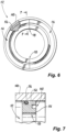
Fig. 8 is a schematic end view of the multi-piece seal carrier ofFig. 1 , showing locating pins of the pieces of the multi-piece seal carrier together for alignment; and -
Fig. 9 is a schematic end view of the multi-piece seal carrier ofFig. 1 , showing bolts for joining the pieces of the multi-piece seal carrier together. - Reference will now be made to the drawings wherein like reference numerals identify similar structural features or aspects of the subject disclosure. For purposes of explanation and illustration, and not limitation, a partial view of an embodiment of a valve assembly in accordance with the disclosure is shown in
Fig. 1 and is designated generally byreference character 100. Other embodiments of systems in accordance with the disclosure, or aspects thereof, are provided inFigs. 2-9 , as will be described. The systems and methods described herein can be used to provide for multi-piece seal carriers in valve assemblies, which allow for one-piece piston spools construction. - The
valve assembly 100 includes afirst sleeve 102 defining apiston bore 104 therein. Asecond sleeve 106 defines apiston bore 108 therein. The piston bore 104 of thefirst sleeve 102 and the piston bore 108 of thesecond sleeve 106 are axially aligned along axis A. Apiston 110 is slidingly engaged in thepiston bores multi-piece seal carrier 112 is engaged axially between thefirst sleeve 102 and thesecond sleeve 106. The plurality ofpieces 114, 116 (labeled inFig. 3 ) of theseal carrier 112 are circumferentially spaced apart from one another withcircumferential gaps 118 spacing thepieces - The
seal carrier 112 extends circumferentially around thepiston 110. Theseal carrier 112 includes axially extendingtabs 120 that seat inside a radiallyinward surface 122 of at least one of thefirst sleeve 102 and thesecond sleeve 106 to prevent radial expansion of theseal carrier 112 which could putface seal 124 in tension. The piston bore 104 of thefirst sleeve 102 has a diameter equal to that of the piston bore 108 of thesecond sleeve 106. - However, those skilled in the art will readily appreciate that these two diameters do not necessarily need to be equal for systems and methods disclosed herein to operate. The systems and methods herein can be applicable to any scenario where it is desirable to add a face seal into a intermediate pressure in a valve assembly (driven by tight or zero leakage requirements), and when the diameters are similar. One diameter needs to grow by about 0.200 inches (0.508 cm) before it is no longer necessary to use a multi-piece seal carrier and there can just be two sleeves. A common face seal geometry is dictated by SAE ARP1234, so the requirement on diameter alignment can be that the two diameters are such that one cannot fit a face seal per industry standard in the end of the smaller sleeve without interrupting the diameters (of
bores 104 or 108). - The
piston 110 is spool shaped, with afirst piston 126 end engaged with thefirst sleeve 102, asecond piston end 128 engaged with thesecond sleeve 106. Aspool section 130 of the piston connects between the first and second piston ends 126, 128. Thespool section 130 has a smaller diameter that both of the first and second piston ends 126, 128. Thefirst piston end 126, thespool section 130, and thesecond piston end 128 are all a single, monolithic piece. The outer diameters of both piston ends 126 and 128 are the same size, so that equal pressures P1 and P4 acting on the outward facing surfaces 134, 136 of the piston ends 126, 128 result in canceled forces on thepiston 110. The case of unequal diameters forbores - The
first sleeve 102 includes afirst port 132 radially extending therethrough for fluid communication of a control fluid at pressure P1 to act on anouter face 134 of thefirst piston end 126 on an opposite side of thefirst piston end 126 from thespool section 130. Thesecond sleeve 106 includes asecond port 138 radially extending therethrough for fluid communication of a control fluid at pressure P4 to act on anouter face 136 of thesecond piston end 128 on an opposite side of thesecond piston end 128 from thespool section 130. Pressure differentials between pressure P1 and pressure P4 result in a force imbalance on thepiston 110 for movement of thepiston 110. - A
face seal 124 is seated is in theseal carrier 112, sealing betweenseal carrier 112 and thesecond sleeve 106. Eachpiece 114, 116 (labeled inFig. 3 ) of the seal carrier includes a circumferential groove 140 (labeled inFig. 3 ) with a matching diameter among thepieces face seal 124 is seated in thegroove 140 of eachpiece Fig. 3 . Thefirst sleeve 102 includes athird port 142 radially extending therethrough for fluid communication of a control fluid at pressure P2 into avolume 144 between the first and second piston ends 134, 136, sharing thevolume 144 with thespool section 130. Thesecond sleeve 106 includes afourth port 146 radially extending therethrough for fluid communication of a control fluid therethrough at pressure P3. - In a first position of the
piston 110 shown inFig. 1 , the second piston end 128 seals against theface seal 124 preventing flow from thethird port 142 to thefourth port 146. Ahousing 148 houses the first andsecond sleeves radial seal 150 around thesecond sleeve 106 seals against thesecond sleeve 106 and against thehousing 148 to stop flow between circumferential gaps 118 (labeled inFig. 3 ) betweenpieces 114, 116 (labeled inFig. 3 ) of theseal carrier 112. The large, two-headed arrow inFig. 1 indicates how theface seal 124 and theradial seal 150 block flow from passing fromport 142 toport 146 when thepiston 110 is in the first position. With reference toFig. 2 , in a second position of thepiston 110, thesecond piston end 128 is spaced apart from theface seal 124 to allow fluid communication between thethird port 142 and thefourth port 146. The large flow arrow inFig. 2 indicates the flow of fluid fromport 142 toport 146. - As shown in
Fig. 3 , in the first position of thepiston 110, the face seal seals around a full circumference of thesecond piston end 128 and of thesecond sleeve 106. The size of thegaps 118 can be designed so theface seal 124 never becomes overstuffed by inward compression ofpieces gaps 118. - With reference now to
Figs. 4 and 5 , asnap ring 152 can be engaged about the twopieces ring carrier 122 to hold the twopieces seal carrier 112 together. Thesnap ring 152 can be engaged into thegrove 154 labeled inFig. 5 after assembly of thepieces first sleeve 102 ofFig. 1 . - With reference to
Figs. 6 and 7 , an o-ring 156 can be engaged about the twopieces pieces seal carrier 112 together as shown inFig. 6 . The o-ring 156 can be assembled on the seal carrier in thegroove 154 after assembly of the twopieces seal carrier 112 can then be fit to the bore of thehousing 148 as shown inFig. 7 . - With reference now to
Fig. 8 , eachpiece seal carrier 112 can include a locatingpin 158, which can be seated in apin bore 160 of theother piece pins 158 and bores 160 are in circumferential faces of thepieces pieces housing 148 shown inFig. 1 . - With reference now to
Fig. 9 , the twopieces bolts 162, e.g. threaded bolts, in thebores 164, e.g. threaded bores, across thegaps 118. This retains thepieces housing 148 ofFig. 1 , and reduces the effects of assembly tolerances. - Potential benefits of systems and methods as disclosed herein include the following. This split collar of the
seal carrier 112 allows the use of a single piece spool,e.g. piston 110, rather than multi-piece spool. This can improve ease of assembly. This can also remove the need to structurally size an interface in the spool where there is less space, e.g. eliminates the need to assemble the piston ends and the spool section of the piston together with a fastener that can break. - The methods and systems of the present disclosure, as described above and shown in the drawings, provide for multi-piece seal carriers in valve assemblies, which allow for one-piece piston spools construction. While the apparatus and methods of the subject disclosure have been shown and described with reference to preferred embodiments, those skilled in the art will readily appreciate that changes and/or modifications may be made thereto without departing from the scope of the invention as defined by the claims.
Claims (15)
- A valve assembly comprising:a first sleeve (102) defining a piston bore (104) therein;a second sleeve (106) defining a piston bore (108) therein, wherein the piston bore of the first sleeve and the piston bore of the second sleeve are axially aligned;a piston (110) slidingly engaged in the piston bores of the first and second sleeves; anda seal carrier (112) with a plurality of pieces, wherein the seal carrier is axially between the first sleeve and the second sleeve, wherein the plurality of pieces of the multi-piece seal carrier are circumferentially spaced apart from one another.
- The assembly as recited in claim 1, wherein the seal carrier (112) extends circumferentially around the piston.
- The assembly as recited in claim 1 or 2, wherein the seal carrier (112) includes axially extending tabs (120) that seat inside a radially inward surface (122) of at least one of the first sleeve and the second sleeve.
- The assembly as recited in any preceding claim, wherein the piston bore of the first sleeve has a diameter equal to that of the piston bore of the second sleeve.
- The assembly as recite in any preceding claim, wherein the piston is spool shaped, with a first piston end (126) engaged with the first sleeve, a second piston end (128) engaged with the second sleeve, and a spool section (130) connecting between the first and second piston ends, wherein the spool section has a smaller diameter that both of the first and second piston ends, and optionally wherein the first piston end, the spool section, and the second piston end are all a single, monolithic piece.
- The assembly as recited in any preceding claim, wherein the first sleeve includes a first port (132) radially extending therethrough for fluid communication of a control fluid to act on an outer face of the first piston end.
- The assembly as recited in claim 6, wherein the second sleeve includes a second port (138) radially extending therethrough for fluid communication of a control fluid to act on an outer face of the second piston end.
- The assembly as recited in claim 7, further comprising a face seal seated in the seal carrier, sealing between seal carrier and second sleeve, and optionally wherein each piece of the seal carrier includes a groove (154) with a matching diameter, wherein the face seal (124) is seated in the groove of each piece.
- The assembly as recited in claim 8, wherein the first sleeve includes a third port (142) radially extending therethrough for fluid communication of a control fluid into a volume with the spool section between the first and second piston ends.
- The assembly as recited in claim 9, wherein the second sleeve includes a fourth port (146) radially extending therethrough for fluid communication of a control fluid therethrough, wherein in a first position of the piston, the second piston end seals against the face seal preventing flow from the third port to the fourth port, and wherein in a second position of the piston, the second piston end is spaced apart from the face seal to allow fluid communication between the third port and the fourth port, and optionally wherein in the first position of the piston, the face seal seals around a full circumference of the second piston end and of the second sleeve.
- The assembly as recited in claim 8, further comprising a housing (148) that houses the first and second sleeves therein, and optionally further comprising a radial seal around the second sleeve sealing against the second sleeve and against the housing (148) to stop flow between circumferential gaps between pieces of the seal carrier.
- The assembly as recited in any preceding claim, wherein there are two pieces (114, 116) of the seal carrier, wherein two circumferential gaps (118) space apart the two pieces from one another.
- The assembly as recited in claim 12, further comprising a snap ring (152) engaged about the two pieces to hold the two pieces of the seal carrier together, or further comprising an o-ring (156) engaged about the two pieces to hold the two pieces of the seal carrier together.
- The assembly as recited in claim 12 or 13, wherein each piece includes a locating pin (158) seated in a pin bore (160) of the other piece.
- The assembly as recited in claim 12, 13 or 14, wherein the two pieces are bolted together across the gaps.
Applications Claiming Priority (1)
| Application Number | Priority Date | Filing Date | Title |
|---|---|---|---|
| US18/080,320 US11927272B1 (en) | 2022-12-13 | 2022-12-13 | Valves with multi-piece sleeves |
Publications (2)
| Publication Number | Publication Date |
|---|---|
| EP4386238A1 true EP4386238A1 (en) | 2024-06-19 |
| EP4386238B1 EP4386238B1 (en) | 2026-01-28 |
Family
ID=89222704
Family Applications (1)
| Application Number | Title | Priority Date | Filing Date |
|---|---|---|---|
| EP23216446.7A Active EP4386238B1 (en) | 2022-12-13 | 2023-12-13 | Valves with multi-piece sleeves |
Country Status (2)
| Country | Link |
|---|---|
| US (1) | US11927272B1 (en) |
| EP (1) | EP4386238B1 (en) |
Citations (6)
| Publication number | Priority date | Publication date | Assignee | Title |
|---|---|---|---|---|
| US2205788A (en) * | 1939-12-29 | 1940-06-25 | Florence Pipe Foundry & Machin | Valve construction |
| US3283783A (en) * | 1963-10-25 | 1966-11-08 | Clary Corp | Multi-way valve |
| US20100319779A1 (en) * | 2009-06-23 | 2010-12-23 | Kent David Harms | Three-position fluid valve for downhole use |
| US20200340584A1 (en) * | 2019-04-23 | 2020-10-29 | Parker-Hannifin Corporation | Segmented seal puzzle joint seal |
| CN215172535U (en) * | 2021-07-16 | 2021-12-14 | 杭州瑞能科技设备有限公司 | Novel low oil pressure emergency safety device |
| WO2022249705A1 (en) * | 2021-05-26 | 2022-12-01 | ジャパン マリンユナイテッド株式会社 | Bow-side sealing structure of stern tube and vessel |
Family Cites Families (10)
| Publication number | Priority date | Publication date | Assignee | Title |
|---|---|---|---|---|
| US2938704A (en) * | 1957-04-02 | 1960-05-31 | Specialties Dev Corp | Seal for reciprocating valve |
| US3565115A (en) * | 1968-09-23 | 1971-02-23 | Beckett Harcum Co | Spool valve |
| US3951381A (en) * | 1974-06-12 | 1976-04-20 | Whitener Robert V | Disc valves |
| US4070005A (en) * | 1974-08-19 | 1978-01-24 | Mcjones Robert W | Valve having an improved seat |
| DE8107889U1 (en) | 1981-03-18 | 1981-10-22 | Festo-Maschinenfabrik Gottlieb Stoll, 7300 Esslingen | PNEUMATIC VALVE ARRANGEMENT |
| US4664151A (en) | 1985-07-08 | 1987-05-12 | Futurecraft Corporation | Valve |
| US9194291B2 (en) * | 2012-08-24 | 2015-11-24 | Hamilton Sundstrand Corporation | Turbomachine windmill bypass valve |
| US10133282B2 (en) * | 2015-09-16 | 2018-11-20 | Proserv Operations, Inc. | Shuttle valve with durable soft seal |
| US10371267B2 (en) * | 2017-01-20 | 2019-08-06 | Hamilton Sundstrand Corporation | Rotary adjustable orifice plate valve |
| US11560813B2 (en) | 2021-03-18 | 2023-01-24 | Schaeffler Technologies AG & Co. KG | Recirculating hydraulic fluid control valve |
-
2022
- 2022-12-13 US US18/080,320 patent/US11927272B1/en active Active
-
2023
- 2023-12-13 EP EP23216446.7A patent/EP4386238B1/en active Active
Patent Citations (6)
| Publication number | Priority date | Publication date | Assignee | Title |
|---|---|---|---|---|
| US2205788A (en) * | 1939-12-29 | 1940-06-25 | Florence Pipe Foundry & Machin | Valve construction |
| US3283783A (en) * | 1963-10-25 | 1966-11-08 | Clary Corp | Multi-way valve |
| US20100319779A1 (en) * | 2009-06-23 | 2010-12-23 | Kent David Harms | Three-position fluid valve for downhole use |
| US20200340584A1 (en) * | 2019-04-23 | 2020-10-29 | Parker-Hannifin Corporation | Segmented seal puzzle joint seal |
| WO2022249705A1 (en) * | 2021-05-26 | 2022-12-01 | ジャパン マリンユナイテッド株式会社 | Bow-side sealing structure of stern tube and vessel |
| CN215172535U (en) * | 2021-07-16 | 2021-12-14 | 杭州瑞能科技设备有限公司 | Novel low oil pressure emergency safety device |
Also Published As
| Publication number | Publication date |
|---|---|
| EP4386238B1 (en) | 2026-01-28 |
| US11927272B1 (en) | 2024-03-12 |
Similar Documents
| Publication | Publication Date | Title |
|---|---|---|
| US20220364645A1 (en) | Hydraulic fluid pump and stuffing box assembly for same | |
| CN111201397B (en) | Multi-channel rotary joint | |
| AU668415B2 (en) | Probe member for undersea hydraulic coupling | |
| EP3857020B1 (en) | Piston load ring seal configurations | |
| US20160356382A1 (en) | High pressure dynamic sealing arrangement | |
| US20150129076A1 (en) | Fuel supply routing assembly for engine to detect fuel leakage | |
| US6162031A (en) | Seal seat for high pressure pumps and vessels | |
| US11261978B2 (en) | Annulus safety valve system and method | |
| US12338702B2 (en) | Oilfield unitized wellhead with integrated internal hanger retainer system | |
| EP4386238B1 (en) | Valves with multi-piece sleeves | |
| US11940053B2 (en) | Shutoff seal assemblies and related valve assemblies and methods | |
| US11493161B2 (en) | Dual-fuel multi-port connector | |
| US20200271230A1 (en) | Valve seat and cage assembly | |
| GB2386167A (en) | Undersea hydraulic coupling with radial seals on probe member | |
| GB2558001A (en) | Seal ring and joint | |
| US20140260956A1 (en) | Circumferential sealing of piston assembly in a piston actuator | |
| US7549678B2 (en) | Systems for actuating a pipe connection | |
| US12313163B2 (en) | Interlocking rotary union seal | |
| US4384728A (en) | Fluid sealing arrangement | |
| US20230235839A1 (en) | Rotary union having pressure sleeve | |
| US12305779B2 (en) | Tube connector systems | |
| GB2549335A (en) | A sealing arrangement | |
| EP2302160A1 (en) | Apparatus to mechanically load a compression member | |
| WO2019134108A1 (en) | Improved spool valve | |
| HK40032137B (en) | Multiple passage rotary union |
Legal Events
| Date | Code | Title | Description |
|---|---|---|---|
| PUAI | Public reference made under article 153(3) epc to a published international application that has entered the european phase |
Free format text: ORIGINAL CODE: 0009012 |
|
| STAA | Information on the status of an ep patent application or granted ep patent |
Free format text: STATUS: THE APPLICATION HAS BEEN PUBLISHED |
|
| AK | Designated contracting states |
Kind code of ref document: A1 Designated state(s): AL AT BE BG CH CY CZ DE DK EE ES FI FR GB GR HR HU IE IS IT LI LT LU LV MC ME MK MT NL NO PL PT RO RS SE SI SK SM TR |
|
| STAA | Information on the status of an ep patent application or granted ep patent |
Free format text: STATUS: REQUEST FOR EXAMINATION WAS MADE |
|
| 17P | Request for examination filed |
Effective date: 20241218 |
|
| GRAP | Despatch of communication of intention to grant a patent |
Free format text: ORIGINAL CODE: EPIDOSNIGR1 |
|
| STAA | Information on the status of an ep patent application or granted ep patent |
Free format text: STATUS: GRANT OF PATENT IS INTENDED |
|
| INTG | Intention to grant announced |
Effective date: 20250731 |
|
| GRAS | Grant fee paid |
Free format text: ORIGINAL CODE: EPIDOSNIGR3 |
|
| GRAA | (expected) grant |
Free format text: ORIGINAL CODE: 0009210 |
|
| STAA | Information on the status of an ep patent application or granted ep patent |
Free format text: STATUS: THE PATENT HAS BEEN GRANTED |
|
| AK | Designated contracting states |
Kind code of ref document: B1 Designated state(s): AL AT BE BG CH CY CZ DE DK EE ES FI FR GB GR HR HU IE IS IT LI LT LU LV MC ME MK MT NL NO PL PT RO RS SE SI SK SM TR |
|
| REG | Reference to a national code |
Ref country code: CH Ref legal event code: F10 Free format text: ST27 STATUS EVENT CODE: U-0-0-F10-F00 (AS PROVIDED BY THE NATIONAL OFFICE) Effective date: 20260128 Ref country code: GB Ref legal event code: FG4D |
|
| REG | Reference to a national code |
Ref country code: DE Ref legal event code: R096 Ref document number: 602023011277 Country of ref document: DE |
|
| REG | Reference to a national code |
Ref country code: IE Ref legal event code: FG4D |
|
| REG | Reference to a national code |
Ref country code: NL Ref legal event code: MP Effective date: 20260128 |
|
| PG25 | Lapsed in a contracting state [announced via postgrant information from national office to epo] |
Ref country code: NL Free format text: LAPSE BECAUSE OF FAILURE TO SUBMIT A TRANSLATION OF THE DESCRIPTION OR TO PAY THE FEE WITHIN THE PRESCRIBED TIME-LIMIT Effective date: 20260128 |
|
| REG | Reference to a national code |
Ref country code: AT Ref legal event code: MK05 Ref document number: 1881632 Country of ref document: AT Kind code of ref document: T Effective date: 20260128 |
|
| PG25 | Lapsed in a contracting state [announced via postgrant information from national office to epo] |
Ref country code: RS Free format text: LAPSE BECAUSE OF FAILURE TO SUBMIT A TRANSLATION OF THE DESCRIPTION OR TO PAY THE FEE WITHIN THE PRESCRIBED TIME-LIMIT Effective date: 20260428 |
|
| PG25 | Lapsed in a contracting state [announced via postgrant information from national office to epo] |
Ref country code: ES Free format text: LAPSE BECAUSE OF FAILURE TO SUBMIT A TRANSLATION OF THE DESCRIPTION OR TO PAY THE FEE WITHIN THE PRESCRIBED TIME-LIMIT Effective date: 20260128 |
|
| PG25 | Lapsed in a contracting state [announced via postgrant information from national office to epo] |
Ref country code: PL Free format text: LAPSE BECAUSE OF FAILURE TO SUBMIT A TRANSLATION OF THE DESCRIPTION OR TO PAY THE FEE WITHIN THE PRESCRIBED TIME-LIMIT Effective date: 20260128 |
|
| PG25 | Lapsed in a contracting state [announced via postgrant information from national office to epo] |
Ref country code: GR Free format text: LAPSE BECAUSE OF FAILURE TO SUBMIT A TRANSLATION OF THE DESCRIPTION OR TO PAY THE FEE WITHIN THE PRESCRIBED TIME-LIMIT Effective date: 20260429 |
|
| REG | Reference to a national code |
Ref country code: LT Ref legal event code: MG9D |
|
| PG25 | Lapsed in a contracting state [announced via postgrant information from national office to epo] |
Ref country code: LT Free format text: LAPSE BECAUSE OF FAILURE TO SUBMIT A TRANSLATION OF THE DESCRIPTION OR TO PAY THE FEE WITHIN THE PRESCRIBED TIME-LIMIT Effective date: 20260128 |
|
| PG25 | Lapsed in a contracting state [announced via postgrant information from national office to epo] |
Ref country code: NO Free format text: LAPSE BECAUSE OF FAILURE TO SUBMIT A TRANSLATION OF THE DESCRIPTION OR TO PAY THE FEE WITHIN THE PRESCRIBED TIME-LIMIT Effective date: 20260428 |
|
| PG25 | Lapsed in a contracting state [announced via postgrant information from national office to epo] |
Ref country code: SE Free format text: LAPSE BECAUSE OF FAILURE TO SUBMIT A TRANSLATION OF THE DESCRIPTION OR TO PAY THE FEE WITHIN THE PRESCRIBED TIME-LIMIT Effective date: 20260128 Ref country code: AT Free format text: LAPSE BECAUSE OF FAILURE TO SUBMIT A TRANSLATION OF THE DESCRIPTION OR TO PAY THE FEE WITHIN THE PRESCRIBED TIME-LIMIT Effective date: 20260128 Ref country code: FI Free format text: LAPSE BECAUSE OF FAILURE TO SUBMIT A TRANSLATION OF THE DESCRIPTION OR TO PAY THE FEE WITHIN THE PRESCRIBED TIME-LIMIT Effective date: 20260128 |
|
| PG25 | Lapsed in a contracting state [announced via postgrant information from national office to epo] |
Ref country code: HR Free format text: LAPSE BECAUSE OF FAILURE TO SUBMIT A TRANSLATION OF THE DESCRIPTION OR TO PAY THE FEE WITHIN THE PRESCRIBED TIME-LIMIT Effective date: 20260128 |
|
| PG25 | Lapsed in a contracting state [announced via postgrant information from national office to epo] |
Ref country code: IS Free format text: LAPSE BECAUSE OF FAILURE TO SUBMIT A TRANSLATION OF THE DESCRIPTION OR TO PAY THE FEE WITHIN THE PRESCRIBED TIME-LIMIT Effective date: 20260528 Ref country code: PT Free format text: LAPSE BECAUSE OF FAILURE TO SUBMIT A TRANSLATION OF THE DESCRIPTION OR TO PAY THE FEE WITHIN THE PRESCRIBED TIME-LIMIT Effective date: 20260528 |
|
| PG25 | Lapsed in a contracting state [announced via postgrant information from national office to epo] |
Ref country code: LV Free format text: LAPSE BECAUSE OF FAILURE TO SUBMIT A TRANSLATION OF THE DESCRIPTION OR TO PAY THE FEE WITHIN THE PRESCRIBED TIME-LIMIT Effective date: 20260128 |
|
| PG25 | Lapsed in a contracting state [announced via postgrant information from national office to epo] |
Ref country code: BG Free format text: LAPSE BECAUSE OF FAILURE TO SUBMIT A TRANSLATION OF THE DESCRIPTION OR TO PAY THE FEE WITHIN THE PRESCRIBED TIME-LIMIT Effective date: 20260128 |