EP4386235A1 - Speed-changing device - Google Patents
Speed-changing device Download PDFInfo
- Publication number
- EP4386235A1 EP4386235A1 EP21959348.0A EP21959348A EP4386235A1 EP 4386235 A1 EP4386235 A1 EP 4386235A1 EP 21959348 A EP21959348 A EP 21959348A EP 4386235 A1 EP4386235 A1 EP 4386235A1
- Authority
- EP
- European Patent Office
- Prior art keywords
- shift
- angle
- drum
- driven
- engagement portion
- Prior art date
- Legal status (The legal status is an assumption and is not a legal conclusion. Google has not performed a legal analysis and makes no representation as to the accuracy of the status listed.)
- Granted
Links
Images







Classifications
-
- F—MECHANICAL ENGINEERING; LIGHTING; HEATING; WEAPONS; BLASTING
- F16—ENGINEERING ELEMENTS AND UNITS; GENERAL MEASURES FOR PRODUCING AND MAINTAINING EFFECTIVE FUNCTIONING OF MACHINES OR INSTALLATIONS; THERMAL INSULATION IN GENERAL
- F16H—GEARING
- F16H63/00—Control outputs from the control unit to change-speed- or reversing-gearings for conveying rotary motion or to other devices than the final output mechanism
- F16H63/02—Final output mechanisms therefor; Actuating means for the final output mechanisms
- F16H63/08—Multiple final output mechanisms being moved by a single common final actuating mechanism
- F16H63/16—Multiple final output mechanisms being moved by a single common final actuating mechanism the final output mechanisms being successively actuated by progressive movement of the final actuating mechanism
- F16H63/18—Multiple final output mechanisms being moved by a single common final actuating mechanism the final output mechanisms being successively actuated by progressive movement of the final actuating mechanism the final actuating mechanism comprising cams
-
- B—PERFORMING OPERATIONS; TRANSPORTING
- B62—LAND VEHICLES FOR TRAVELLING OTHERWISE THAN ON RAILS
- B62M—RIDER PROPULSION OF WHEELED VEHICLES OR SLEDGES; POWERED PROPULSION OF SLEDGES OR SINGLE-TRACK CYCLES; TRANSMISSIONS SPECIALLY ADAPTED FOR SUCH VEHICLES
- B62M25/00—Actuators for gearing speed-change mechanisms specially adapted for cycles
- B62M25/02—Actuators for gearing speed-change mechanisms specially adapted for cycles with mechanical transmitting systems, e.g. cables, levers
-
- F—MECHANICAL ENGINEERING; LIGHTING; HEATING; WEAPONS; BLASTING
- F16—ENGINEERING ELEMENTS AND UNITS; GENERAL MEASURES FOR PRODUCING AND MAINTAINING EFFECTIVE FUNCTIONING OF MACHINES OR INSTALLATIONS; THERMAL INSULATION IN GENERAL
- F16H—GEARING
- F16H61/00—Control functions within control units of change-speed- or reversing-gearings for conveying rotary motion ; Control of exclusively fluid gearing, friction gearing, gearings with endless flexible members or other particular types of gearing
- F16H61/26—Generation or transmission of movements for final actuating mechanisms
- F16H61/28—Generation or transmission of movements for final actuating mechanisms with at least one movement of the final actuating mechanism being caused by a non-mechanical force, e.g. power-assisted
- F16H61/32—Electric motors , actuators or related electrical control means therefor
-
- B—PERFORMING OPERATIONS; TRANSPORTING
- B60—VEHICLES IN GENERAL
- B60Y—INDEXING SCHEME RELATING TO ASPECTS CROSS-CUTTING VEHICLE TECHNOLOGY
- B60Y2200/00—Type of vehicle
- B60Y2200/10—Road Vehicles
- B60Y2200/12—Motorcycles, Trikes; Quads; Scooters
-
- B—PERFORMING OPERATIONS; TRANSPORTING
- B62—LAND VEHICLES FOR TRAVELLING OTHERWISE THAN ON RAILS
- B62M—RIDER PROPULSION OF WHEELED VEHICLES OR SLEDGES; POWERED PROPULSION OF SLEDGES OR SINGLE-TRACK CYCLES; TRANSMISSIONS SPECIALLY ADAPTED FOR SUCH VEHICLES
- B62M25/00—Actuators for gearing speed-change mechanisms specially adapted for cycles
- B62M2025/006—Actuators for gearing speed-change mechanisms specially adapted for cycles with auxiliary shift assisting means
-
- F—MECHANICAL ENGINEERING; LIGHTING; HEATING; WEAPONS; BLASTING
- F16—ENGINEERING ELEMENTS AND UNITS; GENERAL MEASURES FOR PRODUCING AND MAINTAINING EFFECTIVE FUNCTIONING OF MACHINES OR INSTALLATIONS; THERMAL INSULATION IN GENERAL
- F16H—GEARING
- F16H57/00—General details of gearing
- F16H57/02—Gearboxes; Mounting gearing therein
- F16H2057/0203—Gearboxes; Mounting gearing therein the gearbox is associated or combined with a crank case of an engine
-
- F—MECHANICAL ENGINEERING; LIGHTING; HEATING; WEAPONS; BLASTING
- F16—ENGINEERING ELEMENTS AND UNITS; GENERAL MEASURES FOR PRODUCING AND MAINTAINING EFFECTIVE FUNCTIONING OF MACHINES OR INSTALLATIONS; THERMAL INSULATION IN GENERAL
- F16H—GEARING
- F16H59/00—Control inputs to control units of change-speed- or reversing-gearings for conveying rotary motion
- F16H59/68—Inputs being a function of gearing status
- F16H2059/6807—Status of gear-change operation, e.g. clutch fully engaged
-
- F—MECHANICAL ENGINEERING; LIGHTING; HEATING; WEAPONS; BLASTING
- F16—ENGINEERING ELEMENTS AND UNITS; GENERAL MEASURES FOR PRODUCING AND MAINTAINING EFFECTIVE FUNCTIONING OF MACHINES OR INSTALLATIONS; THERMAL INSULATION IN GENERAL
- F16H—GEARING
- F16H61/00—Control functions within control units of change-speed- or reversing-gearings for conveying rotary motion ; Control of exclusively fluid gearing, friction gearing, gearings with endless flexible members or other particular types of gearing
- F16H2061/0075—Control functions within control units of change-speed- or reversing-gearings for conveying rotary motion ; Control of exclusively fluid gearing, friction gearing, gearings with endless flexible members or other particular types of gearing characterised by a particular control method
- F16H2061/0087—Adaptive control, e.g. the control parameters adapted by learning
-
- F—MECHANICAL ENGINEERING; LIGHTING; HEATING; WEAPONS; BLASTING
- F16—ENGINEERING ELEMENTS AND UNITS; GENERAL MEASURES FOR PRODUCING AND MAINTAINING EFFECTIVE FUNCTIONING OF MACHINES OR INSTALLATIONS; THERMAL INSULATION IN GENERAL
- F16H—GEARING
- F16H61/00—Control functions within control units of change-speed- or reversing-gearings for conveying rotary motion ; Control of exclusively fluid gearing, friction gearing, gearings with endless flexible members or other particular types of gearing
- F16H61/26—Generation or transmission of movements for final actuating mechanisms
- F16H61/28—Generation or transmission of movements for final actuating mechanisms with at least one movement of the final actuating mechanism being caused by a non-mechanical force, e.g. power-assisted
- F16H2061/283—Adjustment or calibration of actuator positions, e.g. neutral position
-
- F—MECHANICAL ENGINEERING; LIGHTING; HEATING; WEAPONS; BLASTING
- F16—ENGINEERING ELEMENTS AND UNITS; GENERAL MEASURES FOR PRODUCING AND MAINTAINING EFFECTIVE FUNCTIONING OF MACHINES OR INSTALLATIONS; THERMAL INSULATION IN GENERAL
- F16H—GEARING
- F16H2200/00—Transmissions for multiple ratios
- F16H2200/003—Transmissions for multiple ratios characterised by the number of forward speeds
- F16H2200/0052—Transmissions for multiple ratios characterised by the number of forward speeds the gear ratios comprising six forward speeds
-
- F—MECHANICAL ENGINEERING; LIGHTING; HEATING; WEAPONS; BLASTING
- F16—ENGINEERING ELEMENTS AND UNITS; GENERAL MEASURES FOR PRODUCING AND MAINTAINING EFFECTIVE FUNCTIONING OF MACHINES OR INSTALLATIONS; THERMAL INSULATION IN GENERAL
- F16H—GEARING
- F16H3/00—Toothed gearings for conveying rotary motion with variable gear ratio or for reversing rotary motion
- F16H3/006—Toothed gearings for conveying rotary motion with variable gear ratio or for reversing rotary motion power being selectively transmitted by parallel flow paths, e.g. dual clutch transmissions
Definitions
- the present invention relates to a transmission apparatus that changes a transmission gear ratio of a transmission by driving a shift motor and rotating a shift drum.
- Patent Document 1 JP 2016-70357 A
- the transmission apparatus disclosed in Patent Document 1 includes the pole ratchet mechanism to rotate the shift drum, and newly includes the speed increasing mechanism and the second sensor shaft in addition to the first angle sensor corresponding to the drum angle sensor in order to accurately detect the rotation angle of the shift drum, such that the second angle sensor detects the rotation angle of the second sensor shaft.
- the present invention provides
- the difference angle between the drum shaft conversion spindle integration angle and the detected drum angle reflects deviation between the drum center and the shift driven gear when the drum center is set at the gear position, the difference angle being obtained when it is clear that a relative positional relationship between the drum center and the shift driven gear is a relative positional relationship in which the drive engagement portion and the driven engagement portion are in contact with each other.
- the control value of the shift motor is corrected and learned based on the difference angle, and thereby the deviation between the drum center and the shift driven gear is corrected to accurately control the rotation of the shift drum by the shift motor.
- the fixed state of the drum center can be easily set, and the difference angle between the drum shaft conversion spindle integration angle and the detected drum angle can be accurately learned.
- the fixed state of the drum center can be easily set, and the difference angle between the drum shaft conversion spindle integration angle and the detected drum angle can be accurately learned.
- the average of the difference angles obtained by averaging the difference angle learned at the time of shift-up from the top gear state and the difference angle learned at the time of shift-down from the neutral state can be subtracted from the detected spindle angle to correct the drum shaft conversion spindle integration angle based on the corrected detected spindle angle, and the difference angle between the drum shaft conversion spindle integration angle and the detected drum angle can be learned with higher accuracy by using the corrected drum shaft conversion spindle integration angle.
- the stopped state after the drive engagement portion of the shift driven gear reduces the play angle to abut on the driven engagement portion of the drum center to accompany the driven engagement portion is maintained until the shifting is completed.
- the difference angle between the drum shaft conversion spindle integration angle and the detected drum angle can be learned over a predetermined learning time from the stopped state, and the difference angle between the drum shaft conversion spindle integration angle and the detected drum angle can be accurately learned while the drum center is in the stopped state.
- the shift control device learns the difference angle between the drum shaft conversion spindle integration angle obtained by converting the detected spindle angle into the drum angle and the detected drum angle, over the predetermined learning time from when the shift motor is driven, and the drive engagement portion of the shift driven gear reduces the play angle to abut on the driven engagement portion of the drum center to accompany the driven engagement portion such that the difference angle is maintained as a constant value.
- the difference angle between the drum shaft conversion spindle integration angle and the detected drum angle reflects deviation between the drum center and the shift driven gear when the drum center is set at the gear position, the difference angle being obtained when it is clear that a relative positional relationship between the drum center and the shift driven gear is a relative positional relationship in which the drive engagement portion and the driven engagement portion are in contact with each other.
- the control value of the shift motor is corrected and learned based on the difference angle, and thereby the deviation between the drum center and the shift driven gear is corrected to accurately drive the shift motor.
- the front, rear, left, and right directions are in accordance with a normal standard in which a straight traveling direction of the motorcycle 1 according to the present embodiment is the front, and in the drawings, FR indicates the front, RR indicates the rear, LH indicates the left, and RH indicates the right.
- a rear wheel 23 is rotatably supported by a rear end of the swing arm 21 via a rear wheel axle 22.
- An occupant seat 24 is attached above the seat rail 14, and a fuel tank 25 is mounted in front of the occupant seat 24 and above the main frame 12.
- the power unit P that drives the rear wheel 23 is supported by a plurality of mounting brackets 10a provided on the vehicle body frame 10 and is mounted horizontally with a rotation axis of a crankshaft 32 directed in a right-left vehicle body width direction.
- the power unit P integrally includes a water-cooled two-cylinder four-stroke cycle internal combustion engine 3 and a transmission apparatus 4 connected to the rear side of the internal combustion engine 3.
- the transmission apparatus 4 that shifts a drive force of the internal combustion engine 3 to a predetermined shift stage includes a constant mesh transmission 40, a variable speed drive mechanism 60 that operates shift stages of the transmission 40, and a clutch mechanism 53.
- the drive sprocket 42a is fitted to the left end of the counter shaft 42.
- the clutch outer shaft 41C covers the main-shaft inner shaft 41A from the center toward a right end thereof to be relatively rotatable via the needle bearing 49.
- the main shaft 41 is provided with six drive gears m1 to m6 having transmission ratios from a first speed to a sixth speed, and the counter shaft 42 is provided with six driven gears c1 to c6 from the first speed to the sixth speed.
- gears m1 to m6 and the driven gears c1 to c6 are arranged in the order of the second speed, the sixth speed, the fourth speed, the third speed, the fifth speed, and first speed from the right side and mesh with each other, and the drive gears m1 to m6 and the driven gears c1 to c6 constitute the gear group 50.
- the drive gears m2, m4, and m6 of even-numbered shift stages are provided on the main-shaft outer shaft 41B, and the drive gears m1, m3, and m5 of odd-numbered shift stages are provided on the main-shaft inner shaft 41A.
- a subscript x attached to the reference numerals of the drive gears m1 to m6 and the driven gears c1 to c6 represents a fixed gear integrally molded with the shaft 41
- a subscript w represents a free gear supported to be relatively rotatable with respect to the supported shafts 41 and 42
- a subscript s represents a shifter gear that is rotated integrally with the supported shafts 41 and 42 and is movable in an axial direction.
- a dog clutch 51 is provided between each of the shifter gears m3, m4, c5, and c6 and each of the free gears m5, m6, c1, c2, c3, and c4 adjacent to each of the shifter gears m3, m4, c5, and c6.
- the dog clutch 51 meshes with each of the approaching gears, so that both the approaching gears are connected to each other to be relatively non-rotatable.
- a fork groove 52 with which a fork portion of a shift fork 87 to be described below engages is formed along a circumferential direction of the outer circumferential surface.
- Power of the crankshaft 32 is transmitted to the clutch mechanism 53 via the primary drive gear 33 fitted to the crankshaft 32 and the primary driven gear 54, and the power is transmitted from the crankshaft 32 to the main-shaft inner shaft 41A and the main-shaft outer shaft 41B by selectively connecting the first hydraulic clutch 53A and the second hydraulic clutch 53B by the hydraulic circuit 55.
- an outer diameter of a right side portion of the cylindrical portion 82a is increased to form an increased diameter disk portion 82b
- an outer diameter of a right opening end portion of the cylindrical portion 82a on the right side from the increased diameter disk portion 82b is increased to form a star-shaped cam 82c
- a fan-shaped driven engagement portion 82d is formed at the cylindrical portion 82a on the left side from the increased diameter disk portion 82b to expand outward in a radial direction with a rotation center axis as a fan core and project leftward from the increased diameter disk portion 82b.
- the fan-shaped recessed portion 83c is recessed in and penetrates the hollow disk portion 83b in the rotation axis direction.
- the shift spindle 75 is directed in the right-left direction, bridges a space between the left case side wall 31D L and the right case side wall 31D R of the lower crankcase 31D, and is rotatably supported.
- the shift drive gear 76 meshes with (the gear teeth 83e of) the shift driven gear 83 loosely fitted to the drum center 82 integrally attached to a right end of the shift drum 80 to be relatively rotatable with a play angle in the circumferential direction.
- a stopper mechanism 90 in which a stopper roller 93 pivotally supported by a distal end of a swing-biased stopper arm 92 is pressed is provided at the uneven cam surface of the star-shaped cam 82c.
- the shift motor 61 is driven to control the shift driven gear 83 to be rotated toward the neutral position (target position) of the next-stage gear position.
- the shift driven gear 83 is located at the neutral position where the first play angle ⁇ 1 and the second play angle ⁇ 2 on both sides of the driven engagement portion 82d are equal.
- a difference angle ⁇ between the drum shaft conversion spindle integration angle ⁇ s and the detected drum angle ⁇ d when a certain gear position is set does not indicate the deviation of the shift driven gear 83 from the neutral position with respect to the drum center 82.
- the difference angle ⁇ between the drum shaft conversion spindle integration angle ⁇ s and the detected drum angle ⁇ d learned when the drive engagement portion 83d of the shift driven gear 83 reduces the play angle to be in contact with the driven engagement portion 82d of the drum center 82 reflects the deviation between the drum center 82 and the shift driven gear 83 when the drum center 82 is positioned at the gear position.
- the shift motor 61 is further driven in the shift-up direction, and the difference angle ⁇ between the drum shaft conversion spindle integration angle ⁇ s and the detected drum angle ⁇ d is learned, so that the learning can be performed with little influence on shifting work.
- the difference angle ⁇ between the drum shaft conversion spindle integration angle ⁇ s and the detected drum angle ⁇ d learned when the drive engagement portion 83d of the shift driven gear 83 reduces the play angle to be in contact with the driven engagement portion 82d of the drum center 82 reflects the deviation between the drum center 82 and the shift driven gear 83 when the drum center 82 is positioned at the gear position.
Landscapes
- Engineering & Computer Science (AREA)
- General Engineering & Computer Science (AREA)
- Mechanical Engineering (AREA)
- Chemical & Material Sciences (AREA)
- Combustion & Propulsion (AREA)
- Transportation (AREA)
- Gear-Shifting Mechanisms (AREA)
- Control Of Transmission Device (AREA)
Abstract
Description
- The present invention relates to a transmission apparatus that changes a transmission gear ratio of a transmission by driving a shift motor and rotating a shift drum.
-
Patent Document 1 discloses an example of a transmission apparatus that accurately detects a rotation angle of a shift drum. - Patent Document 1:
JP 2016-70357 A - The transmission apparatus disclosed in
Patent Document 1 includes a dual-clutch transmission, and a variable speed drive mechanism that shifts the transmission changes and shifts a gear pair that transmits power of the transmission by the movement of a shift fork guided to a shift drum when the shift drum is rotated by driving a shift motor. - When the shift motor is driven, a shift spindle is rotated via a reduction gear mechanism, and a pole ratchet mechanism intermittently rotates the shift drum by the rotation of a master arm integrated with the shift spindle.
- In a transmission apparatus including a dual-clutch transmission, when many shift stages are set, the number of gear positions of the shift drum is further increased, and intervals between the gear positions become narrower.
- As gear position intervals of the shift drum become narrower, it is required to accurately control the rotation of the shift drum, and for this purpose, it is necessary to accurately detect a rotation angle of the shift drum.
- In this respect, a shift drum angle detection device in the transmission apparatus according to
Patent Document 1 includes a first angle sensor (corresponding to a drum angle sensor) that detects a rotation angle of a first sensor shaft integrated with the shift drum, and particularly includes a second angle sensor that detects a rotation angle of a second sensor shaft subjected to a speed increase of the rotation of the first sensor shaft via a speed increasing mechanism, thereby accurately detecting the rotation angle of the shift drum by using the rotation angles detected by each of the first angle sensor and the second angle sensor. - The transmission apparatus disclosed in
Patent Document 1 includes the pole ratchet mechanism to rotate the shift drum, and newly includes the speed increasing mechanism and the second sensor shaft in addition to the first angle sensor corresponding to the drum angle sensor in order to accurately detect the rotation angle of the shift drum, such that the second angle sensor detects the rotation angle of the second sensor shaft. - As described above, in
Patent Document 1, the number of components such as the pole ratchet mechanism in the variable speed drive mechanism is large, and a complicated structure is configured. In this manner, the speed increasing mechanism and the second sensor shaft for detecting the rotation angle of the shift drum are further provided, thereby, further increasing the number of components and increasing costs. - The present invention has been made in view of such points, and an object of the present invention is to provide, at a low cost, a transmission apparatus that accurately controls rotation of a shift drum by a shift motor while decreasing the number of components of a variable speed drive mechanism.
- In order to achieve the above object, the present invention provides
- a transmission apparatus including: a transmission including a gear pair having different transmission gear ratios for transmitting power; and
- a variable speed drive mechanism that changes and shifts the gear pair that transmits power of the transmission by movement of a shift fork guided to a shift drum when the shift drum is rotated by being driven by a shift motor, in which
- the variable speed drive mechanism includes
- a drum center that is provided at an end portion of the shift drum and is rotated together with the shift drum,
- a stopper mechanism that positions the drum center at an angular position of each gear position,
- a shift driven gear that is rotated in synchronization with the shift motor and is disposed to be engageable with the drum center,
- a shift spindle that is rotated in synchronization with the shift motor and integrally has a shift drive gear that meshes with the shift driven gear at a predetermined reduction ratio, and
- a configuration in which a drive engagement portion formed in the shift driven gear and a driven engagement portion formed in the drum center are engageable with each other in a circumferential direction with a play angle between the drive engagement portion and the driven engagement portion in the circumferential direction, the variable speed drive mechanism including
- a drum angle sensor that detects a rotation angle of the shift drum,
- a spindle angle sensor that detects a rotation angle of the shift spindle, and
- a shift control device that controls driving of the shift motor based on a control value for rotating the shift driven gear to a target position, and
- the shift control device corrects and learns the control value based on a difference angle between a drum shaft conversion spindle integration angle obtained by converting a detected spindle angle detected by the spindle angle sensor into a drum angle and a detected drum angle detected by the drum angle sensor, over a predetermined learning time from when the shift motor is driven, and the drive engagement portion of the shift driven gear reduces the play angle to abut on the driven engagement portion of the drum center to accompany the driven engagement portion.
- According to this configuration, the variable speed drive mechanism is provided in which the shift drive gear provided integrally to the shift spindle that is rotated in synchronization with the shift motor meshes with the shift driven gear at the predetermined reduction ratio, and the drum center that is rotated by loosely being fitted in the shift driven gear in the circumferential direction rotates the shift drum integrally. Hence, the pole ratchet mechanism and the like can be eliminated to reduce the number of components and simplify the structure, the spindle angle sensor only needs to detect the rotation angle of the shift spindle, and there is no need to provide a mechanism for another angle sensor. Hence, the number of components can be further reduced to achieve a simple structure and cost reduction.
- In addition, the shift control device learns the difference angle between the drum shaft conversion spindle integration angle obtained by converting the detected spindle angle into the drum angle and the detected drum angle, over the predetermined learning time from when the shift motor is driven, and the drive engagement portion of the shift driven gear reduces the play angle to abut on the driven engagement portion of the drum center to accompany the driven engagement portion such that the difference angle is maintained as a constant value. Hence, it can be estimated that the difference angle between the drum shaft conversion spindle integration angle and the detected drum angle reflects deviation between the drum center and the shift driven gear when the drum center is set at the gear position, the difference angle being obtained when it is clear that a relative positional relationship between the drum center and the shift driven gear is a relative positional relationship in which the drive engagement portion and the driven engagement portion are in contact with each other. In addition, the control value of the shift motor is corrected and learned based on the difference angle, and thereby the deviation between the drum center and the shift driven gear is corrected to accurately control the rotation of the shift drum by the shift motor.
- In a preferred embodiment of the present invention,
- the shift control device performs
- learning of the difference angle between the drum shaft conversion spindle integration angle and the detected drum angle, over a predetermined learning time from a stopped state after the shift motor is further driven in a shift-up direction when the transmission is set in a top gear state, and the drive engagement portion of the shift driven gear reduces the play angle to abut on the driven engagement portion of the drum center to accompany the driven engagement portion.
- According to this configuration, the stopped state after the shift motor is further driven in the shift-up direction when the transmission is set in the top gear state, and the drive engagement portion of the shift driven gear reduces the play angle to abut on the driven engagement portion of the drum center to accompany the driven engagement portion is stable, with the drum center entering a fixed state. Hence, the fixed state of the drum center can be easily set, and the difference angle between the drum shaft conversion spindle integration angle and the detected drum angle can be accurately learned.
- When the transmission is set in the top gear state, the shift motor is further driven in the shift-up direction, and the difference angle between the drum shaft conversion spindle integration angle and the detected drum angle is learned, so that the learning can be performed with little influence on shifting work.
- In the preferred embodiment of the present invention,
- the shift control device performs
- learning of the difference angle between the drum shaft conversion spindle integration angle and the detected drum angle, over a predetermined learning time from a stopped state after the shift motor is further driven in a shift-down direction when the transmission is set in a neutral state, and the drive engagement portion of the shift driven gear reduces the play angle to abut on the driven engagement portion of the drum center to accompany the driven engagement portion.
- According to this configuration, the stopped state after the shift motor is further driven in the shift-down direction when the transmission is set in the neutral state, and the drive engagement portion of the shift driven gear reduces the play angle to abut on the driven engagement portion of the drum center to accompany the driven engagement portion is stable, with the drum center entering a fixed state. Hence, the fixed state of the drum center can be easily set, and the difference angle between the drum shaft conversion spindle integration angle and the detected drum angle can be accurately learned.
- When the transmission is set in the neutral state, the shift motor is further driven in the shift-down direction, and the difference angle between the drum shaft conversion spindle integration angle and the detected drum angle is learned, so that the learning can be performed with little influence on shifting work.
- In the preferred embodiment of the present invention,
- the shift control device performs
- learning of the difference angle between the drum shaft conversion spindle integration angle and the detected drum angle, over a predetermined learning time from a stopped state after the shift motor is further driven in a shift-up direction when the transmission is set in a top gear state, and the drive engagement portion of the shift driven gear reduces the play angle to abut on the driven engagement portion of the drum center to accompany the driven engagement portion,
- learning of the difference angle between the drum shaft conversion spindle integration angle and the detected drum angle, over a predetermined learning time from a stopped state after the shift motor is further driven in a shift-down direction when the transmission is set in a neutral state, and the drive engagement portion of the shift driven gear reduces the play angle to abut on the driven engagement portion of the drum center to accompany the driven engagement portion, and
- correcting of the drum shaft conversion spindle integration angle based on an average of difference angles obtained by averaging the difference angle learned at the time of shift-up from the top gear state and the difference angle learned at the time of shift-down from the neutral state, and learning of the difference angle between the corrected drum shaft conversion spindle integration angle and the detected drum angle detected by the drum angle sensor.
- According to this configuration, the average of the difference angles obtained by averaging the difference angle learned at the time of shift-up from the top gear state and the difference angle learned at the time of shift-down from the neutral state can be subtracted from the detected spindle angle to correct the drum shaft conversion spindle integration angle based on the corrected detected spindle angle, and the difference angle between the drum shaft conversion spindle integration angle and the detected drum angle can be learned with higher accuracy by using the corrected drum shaft conversion spindle integration angle.
- In the preferred embodiment of the present invention,
- the shift control device performs
- learning of the difference angle between the drum shaft conversion spindle integration angle and the detected drum angle, over a predetermined learning time from a stopped state after the shift motor is driven to shift the transmission, and the drive engagement portion of the shift driven gear reduces the play angle to abut on the driven engagement portion of the drum center to accompany the driven engagement portion.
- According to this configuration, when the shift motor is driven to shift the transmission, the stopped state after the drive engagement portion of the shift driven gear reduces the play angle to abut on the driven engagement portion of the drum center to accompany the driven engagement portion is maintained until the shifting is completed. Hence, the difference angle between the drum shaft conversion spindle integration angle and the detected drum angle can be learned over a predetermined learning time from the stopped state, and the difference angle between the drum shaft conversion spindle integration angle and the detected drum angle can be accurately learned while the drum center is in the stopped state.
- According to the present invention, the variable speed drive mechanism is provided in which the shift drive gear provided integrally to the shift spindle that is rotated in synchronization with the shift motor meshes with the shift driven gear at the predetermined reduction ratio, and the drum center that is rotated by loosely being fitted in the shift driven gear in the circumferential direction rotates the shift drum integrally. Hence, the number of components can be reduced to simplify the structure, and further, the spindle angle sensor only needs to detect the rotation angle of the existing shift spindle, and thus the number of components can be further reduced to achieve a simple structure.
- In addition, the shift control device learns the difference angle between the drum shaft conversion spindle integration angle obtained by converting the detected spindle angle into the drum angle and the detected drum angle, over the predetermined learning time from when the shift motor is driven, and the drive engagement portion of the shift driven gear reduces the play angle to abut on the driven engagement portion of the drum center to accompany the driven engagement portion such that the difference angle is maintained as a constant value. Hence, it can be estimated that the difference angle between the drum shaft conversion spindle integration angle and the detected drum angle reflects deviation between the drum center and the shift driven gear when the drum center is set at the gear position, the difference angle being obtained when it is clear that a relative positional relationship between the drum center and the shift driven gear is a relative positional relationship in which the drive engagement portion and the driven engagement portion are in contact with each other. In addition, the control value of the shift motor is corrected and learned based on the difference angle, and thereby the deviation between the drum center and the shift driven gear is corrected to accurately drive the shift motor.
-
-
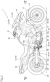
Fig. 1 is a right side view of a motorcycle equipped with a power unit according to an embodiment of the present invention. -
Fig. 2 is a right side view of the power unit. -
Fig. 3 is a left side view of the power unit. -
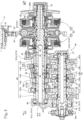
Fig. 4 is a developed cross-sectional view of the power unit along an arrow line IV-IV inFig. 2 . -
Fig. 5 is a left side view illustrating a reduction gear mechanism part of the power unit. -
Fig. 6 is a partial right side view of a lower crankcase of the power unit. -
Fig. 7 is a developed cross-sectional view of a main part of the power unit along an arrow line VII-VII inFig. 5 . -
Fig. 8 is a right side view of a drum center. -
Fig. 9 is a left side view of the drum center. -
Fig. 10 is a cross-sectional view of the drum center along an arrow line X-X inFigs. 8 and 9 . -
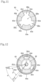
Fig. 11 is a left side view of a shift driven gear. -
Fig. 12 is a left side view illustrating a loosely fitted state of the drum center in the shift driven gear when one gear position is set. -
Fig. 13 is a left side view illustrating a state of the drum center and the shift driven gear when a drive engagement portion of the shift driven gear abuts on a driven engagement portion of the drum center. -
Fig. 14 is a left side view illustrating a loosely fitted state of the drum center in the shift driven gear when movement is performed and the next-stage gear position is set. -
Fig. 15 is a simplified block diagram of a control system of a shift control device. -
Fig. 16 is a graph illustrating changes of a drum shaft conversion spindle integration angle and a detected drum angle at the time of shift-up direction learning. -
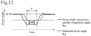
Fig. 17 is a graph illustrating changes of the drum shaft conversion spindle integration angle and the detected drum angle at the time of shift-down direction learning. -
Fig. 18 is a graph illustrating changes of the drum shaft conversion spindle integration angle and the detected drum angle at the time of shifting process learning. - Hereinafter, an embodiment according to the present invention will be described with reference to
Figs. 1 to 16 . -
Fig. 1 is a side view of amotorcycle 1 that is a saddle-type vehicle equipped with a power unit according to an embodiment to which the present invention is applied. - In the description of the present specification, the front, rear, left, and right directions are in accordance with a normal standard in which a straight traveling direction of the
motorcycle 1 according to the present embodiment is the front, and in the drawings, FR indicates the front, RR indicates the rear, LH indicates the left, and RH indicates the right. - As illustrated in
Fig. 1 , avehicle body frame 10 of themotorcycle 1 includes ahead pipe 11 disposed in a front portion, amain frame 12 that extends rearward and obliquely downward from thehead pipe 11 and is curved halfway to extend rearward, acenter frame 13 extending downward from a rear end of themain frame 12, aseat rail 14 extending rearward from an upper portion of thecenter frame 13, a mid-stay 15 bridging a space between a rear portion of thecenter frame 13 and a rear portion of theseat rail 14, and adown frame 16 extending downward from thehead pipe 11. - The
head pipe 11 steerably supports afront fork 17 that rotatably supports afront wheel 18 at a lower end portion. - A steering
handlebar 19 is connected to an upper end portion of thefront fork 17. Aswing arm 21 is swingably supported by thecenter frame 13 via apivot shaft 20. - A
rear wheel 23 is rotatably supported by a rear end of theswing arm 21 via arear wheel axle 22. - An
occupant seat 24 is attached above theseat rail 14, and afuel tank 25 is mounted in front of theoccupant seat 24 and above themain frame 12. - In the
motorcycle 1, the power unit P that drives therear wheel 23 is supported by a plurality of mountingbrackets 10a provided on thevehicle body frame 10 and is mounted horizontally with a rotation axis of acrankshaft 32 directed in a right-left vehicle body width direction. - An
endless chain 26 bridges a space between adrive sprocket 42a fit-attached to an output shaft (counter shaft 42) of the power unit P and a drivensprocket 22a fit-attached to the rear wheel axle 22 (seeFig. 3 ). - As illustrated in
Fig. 2 , the power unit P integrally includes a water-cooled two-cylinder four-stroke cycleinternal combustion engine 3 and a transmission apparatus 4 connected to the rear side of theinternal combustion engine 3. - In the power unit P, a
crankcase 31 rotatably supporting thecrankshaft 32 extends rearward to house the transmission apparatus 4. - The
crankcase 31 is configured to be divided vertically into anupper crankcase 31U and alower crankcase 31D. - The
upper crankcase 31U is configured to include a leftcase side wall 31UL and a rightcase side wall 31UR facing each other on the left and right sides and an upper case peripheral wall 31Us integrally formed by extending toward the left and right sides to both upper peripheral edges excluding split surfaces of the left and right case side walls. Thelower crankcase 31D is configured to include a leftcase side wall 31DL and a rightcase side wall 31DR facing each other on the left and right sides and a lower caseperipheral wall 31DS integrally formed by extending toward the left and right sides to both lower peripheral edges excluding split surfaces of the left and right case side walls. - On a front half portion of the upper case peripheral wall 31Us of the
upper crankcase 31U, acylinder block 34, acylinder head 35, and ahead cover 36 are sequentially overlapped and is tilted forward to project forward and obliquely upward. - A bottom portion of the lower case
peripheral wall 31DS of thelower crankcase 31D is opened, and anoil pan 37 is provided to bulge downward. - An opening on a right side of a cylinder wall formed by combining the upper case peripheral wall 31Us and the lower case
peripheral wall 31DS of thecrankcase 31 is covered with a right crankcase cover 38R (seeFig. 4 ), and an opening on a left side of the cylinder wall is covered with aleft crankcase cover 38L. - The
crankshaft 32 directed in the right-left vehicle body width direction is pivotally supported by the split surfaces of theupper crankcase 31U and thelower crankcase 31D. - That is, the left
case side wall 31UL and the rightcase side wall 31UR facing each other on the left and right sides of theupper crankcase 31U are combined with the leftcase side wall 31DL and the rightcase side wall 31DR facing each other on the left and right sides of thelower crankcase 31D, respectively, by the split surfaces and pivotally support thecrankshaft 32 to sandwich the crankshaft. - The transmission apparatus 4 that shifts a drive force of the
internal combustion engine 3 to a predetermined shift stage includes aconstant mesh transmission 40, a variable speed drive mechanism 60 that operates shift stages of thetransmission 40, and aclutch mechanism 53. - With reference to
Fig. 4 , thetransmission 40 includes a constantmesh gear group 50 provided on amain shaft 41 and thecounter shaft 42. - As illustrated in
Figs. 2 and4 , themain shaft 41 is disposed in theupper crankcase 31U to be parallel to the rotation axis of thecrankshaft 32, obliquely above the rear side of thecrankshaft 32. - The
main shaft 41 is rotatably supported at a left end thereof by the leftcase side wall 31UL of theupper crankcase 31U via aball bearing 43, at a center thereof by the rightcase side wall 31UR of theupper crankcase 31U via aball bearing 44, and at a right end thereof by the right crankcase cover 38R via aball bearing 45. - The
counter shaft 42 is disposed to be parallel to themain shaft 41 by being sandwiched between the upper andlower crankcases main shaft 41. - The
counter shaft 42 is rotatably supported such that a left end thereof penetrates aball bearing 46, a portion thereof close to the left end is sandwiched between the upper andlower crankcases ball bearing 46, and a right end thereof is sandwiched between the upper andlower crankcases needle bearing 47. - The
drive sprocket 42a is fitted to the left end of thecounter shaft 42. - As illustrated in
Fig. 4 , themain shaft 41 includes a long main-shaft inner shaft 41A, a main-shaftouter shaft 41B, and a clutchouter shaft 41C. - The main-shaft
outer shaft 41B covers the main-shaft inner shaft 41A from a center to a center of a left half portion of the main-shaft inner shaft 41A to be relatively rotatable via aneedle bearing 48. - The clutch
outer shaft 41C covers the main-shaft inner shaft 41A from the center toward a right end thereof to be relatively rotatable via theneedle bearing 49. - The
main shaft 41 is provided with six drive gears m1 to m6 having transmission ratios from a first speed to a sixth speed, and thecounter shaft 42 is provided with six driven gears c1 to c6 from the first speed to the sixth speed. - Of the drive gears m1 to m6 and the driven gears c1 to c6, corresponding gears are arranged in the order of the second speed, the sixth speed, the fourth speed, the third speed, the fifth speed, and first speed from the right side and mesh with each other, and the drive gears m1 to m6 and the driven gears c1 to c6 constitute the
gear group 50. - The drive gears m2, m4, and m6 of even-numbered shift stages are provided on the main-shaft
outer shaft 41B, and the drive gears m1, m3, and m5 of odd-numbered shift stages are provided on the main-shaft inner shaft 41A. - In
Fig. 4 , a subscript x attached to the reference numerals of the drive gears m1 to m6 and the driven gears c1 to c6 represents a fixed gear integrally molded with theshaft 41, a subscript w represents a free gear supported to be relatively rotatable with respect to the supportedshafts shafts - That is, the first speed drive gear m1 and the second speed drive gear m2 are fixed gears, the fifth speed drive gear m5, the sixth speed drive gear m6, the first speed driven gear c1, the second speed driven gear c2, the third speed driven gear c3, and the fourth speed driven gear c4 are free gears, and the third speed drive gear m3, the fourth speed drive gear m4, the fifth speed driven gear c5, and the sixth speed driven gear c6 are shifter gears.
- A
dog clutch 51 is provided between each of the shifter gears m3, m4, c5, and c6 and each of the free gears m5, m6, c1, c2, c3, and c4 adjacent to each of the shifter gears m3, m4, c5, and c6. When the shifter gears m3, m4, c5, and c6 approach the adjacent free gears m5, m6, c1, c2, c3, and c4, thedog clutch 51 meshes with each of the approaching gears, so that both the approaching gears are connected to each other to be relatively non-rotatable. - In an outer circumferential surface of each of the shifter gears m3, m4, c5, and c6, a
fork groove 52 with which a fork portion of ashift fork 87 to be described below engages is formed along a circumferential direction of the outer circumferential surface. - A right half portion of the
main shaft 41 is provided with theclutch mechanism 53 of a dual-clutch transmission which includes a first hydraulic clutch 53A and a second hydraulic clutch 53B arranged with a primary drivengear 54 interposed therebetween, the primary drivengear 54 being fitted to a center of a clutchouter shaft 41C to be relatively non-rotatable. - Power of the
crankshaft 32 is transmitted to theclutch mechanism 53 via theprimary drive gear 33 fitted to thecrankshaft 32 and the primary drivengear 54, and the power is transmitted from thecrankshaft 32 to the main-shaft inner shaft 41A and the main-shaftouter shaft 41B by selectively connecting the first hydraulic clutch 53A and the second hydraulic clutch 53B by thehydraulic circuit 55. - As illustrated in
Fig. 7 , the variable speed drive mechanism 60 that moves each of the shifter gears m3, m4, c5, and c6 of thetransmission 40 to switch between shift stages includes ashift motor 61, areduction gear mechanism 70, ashift spindle 75, ashift drum 80, ashift fork shaft 86, and theshift fork 87. - The
shift drum 80 includes a cylindrical drummain body 80A and a drum leftshaft portion 80B, and the drum leftshaft portion 80B is pivotally supported by the leftcase side wall 31DL and theleft crankcase cover 38L via aneedle bearing 84. - A
drum center 82 is coaxially fixed to, with abolt 81, a right end portion of a rightcylindrical portion 80AR on the right side of a portion of the drummain body 80A where alead groove 80v is formed, and a joint portion between the drum center and the right cylindrical portion is pivotally supported by the rightcase side wall 31DR via aball bearing 85. - The
shift drum 80 is disposed below themain shaft 41 to be parallel to themain shaft 41, that is, to be directed in a right-left direction, and is rotatably supported by theneedle bearing 84 and theball bearing 85. - An end portion of the drum left
shaft portion 80B penetrating theneedle bearing 84 of theshift drum 80 is attached to adrum angle sensor 89 provided at a gear case cover 65 to be described below. - The
drum angle sensor 89 detects a rotation angle of theshift drum 80. - With reference to
Figs. 8 to 10 , in thedrum center 82 fixed to a right end portion of theshift drum 80, an outer diameter of a right side portion of thecylindrical portion 82a is increased to form an increaseddiameter disk portion 82b, an outer diameter of a right opening end portion of thecylindrical portion 82a on the right side from the increaseddiameter disk portion 82b is increased to form a star-shapedcam 82c, and a fan-shaped drivenengagement portion 82d is formed at thecylindrical portion 82a on the left side from the increaseddiameter disk portion 82b to expand outward in a radial direction with a rotation center axis as a fan core and project leftward from the increaseddiameter disk portion 82b. - Three driven
engagement portions 82d radially project from an outer circumferential surface of thecylindrical portion 82a at equal intervals in a circumferential direction thereof. - In the
drum center 82, adecreased diameter portion 82e formed by decreasing a diameter of an end portion of a left opening of thecylindrical portion 82a comes into contact with the right end portion of the rightcylindrical portion 80AR of theshift drum 80 and is fixed with abolt 81. - A shift driven
gear 83 is pivotally supported on the outer circumferential surface of thecylindrical portion 82a of thedrum center 82 in a relatively rotatable manner. - As illustrated in
Fig. 11 , the shift drivengear 83 has a hollow disk shape, and a fan-shaped recessedportion 83c recessed in a rotation axis direction is formed in ahollow disk portion 83b on an outer circumference of ahollow circle 83a of the shift driven gear. The fan-shaped recessedportion 83c expands outward in the radial direction with the rotation center axis as a fan core. - The fan-shaped recessed
portion 83c is recessed in and penetrates thehollow disk portion 83b in the rotation axis direction. - A pair of side edge portions forming a pair of side edges of the fan shape of the fan-shaped recessed
portion 83c in thehollow disk portion 83b of the shift drivengear 83 is a pair ofdrive engagement portions 83d. - Three fan-shaped recessed
portions 83c of the shift drivengear 83 are radially formed to project from thehollow circle 83a at equal intervals in the circumferential direction. -
Gear teeth 83e are formed on an outer circumferential edge of thehollow disk portion 83b of the shift drivengear 83. - With reference to
Fig. 12 , an inner diameter of thehollow disk portion 83b of the shift driven gear 83 (an outer diameter of thehollow circle 83a) is substantially equal to an outer diameter of thecylindrical portion 82a of thedrum center 82, thecylindrical portion 82a of thedrum center 82 is fitted in thehollow circle 83a inside thehollow disk portion 83b of the shift drivengear 83, and the three drivenengagement portions 82d of thedrum center 82 are fitted in the three fan-shaped recessedportions 83c of the shift drivengear 83. - An angle α between a pair of side edges of the fan-shaped recessed
portion 83c of the shift driven gear 83 (an angle between a pair ofdrive engagement portions 83d opened in a fan shape) is larger than an angle β between a pair of side edges of the fan-shaped drivenengagement portion 82d of thedrum center 82, and the drivenengagement portion 82d of thedrum center 82 is loosely fitted to be relatively rotatable with a play angle θ in the circumferential direction between a pair ofdrive engagement portions 83d which is a pair of side edge portions of the shift drivengear 83. -
Fig. 12 illustrates a state where the vehicle is stopped at a certain gear position, and there are a first play angle Θ1 and a second play angle Θ2 on both sides of the drivenengagement portion 82d. - The sum of the first play angle Θ1 and the second play angle θ2 is a so-called play angle θ (= θ1 + θ2 = α - β).
- As illustrated in
Fig. 3 , aleft crankcase cover 38L covering the left side of the leftcase side wall 31DL of thelower crankcase 31D is provided with thereduction gear mechanism 70 covered with the gear case cover 65 provided slightly rearward from the center. - As illustrated in
Fig. 7 , thereduction gear mechanism 70 is provided as a reduction gear train in a gear case between theleft crankcase cover 38L and the gear case cover 65 attached to the left side thereof. - The
shift motor 61 is attached to a lower portion of the gear case cover 65 to project leftward, and adrive gear 71 formed on a drive shaft of theshift motor 61 penetrates the gear case cover 65 rightward and projects in a gear case (seeFig. 7 ). - On the other hand, in the vicinity of the lower side of the
shift drum 80, theshift spindle 75 is directed in the right-left direction, bridges a space between the leftcase side wall 31DL and the rightcase side wall 31DR of thelower crankcase 31D, and is rotatably supported. - As illustrated in
Fig. 7 , theshift spindle 75 penetrates the rightcase side wall 31DR rightward, and a right end of the shift spindle reaches theright crankcase cover 38R and is attached to aspindle angle sensor 78 provided in theright crankcase cover 38R. - A rotation angle of the
shift spindle 75 is detected by thespindle angle sensor 78. - A
shift drive gear 76 is fit-attached to a portion of theshift spindle 75, the portion penetrating the rightcase side wall 31DR rightward. - The
shift drive gear 76 meshes with (thegear teeth 83e of) the shift drivengear 83 loosely fitted to thedrum center 82 integrally attached to a right end of theshift drum 80 to be relatively rotatable with a play angle in the circumferential direction. - The shift driven
gear 83 has more teeth than theshift drive gear 76, is decelerated, and transmits power. - As illustrated in
Fig. 7 , theshift spindle 75 penetrates the leftcase side wall 31DL leftward, and a left end of theshift spindle 75 is inserted into the gear case. - The
reduction gear mechanism 70 is formed between a spindle drivengear 74 fit-attached to the left end of theshift spindle 75 and thedrive gear 71 of the drive shaft of theshift motor 61. - Two first and
second gear shafts drive gear 71 and the spindle drivengear 74 to be directed in the right-left direction, and both ends of each of the first and second gear shafts are supported by thegear case cover 65 and theleft crankcase cover 38L to rotatably bridge a space therebetween. - The
drive gear 71 of theshift motor 61 meshes with a large-diameter gear 72L of thefirst gear shaft 72, a small-diameter gear 72S of thefirst gear shaft 72 meshes with an idle gear 73I of thesecond gear shaft 73, and the idle gear 73I of thesecond gear shaft 73 meshes with the spindle drivengear 74 of theshift spindle 75 such that thereduction gear mechanism 70 is configured. - Hence, rotation of a drive gear 62 of the
shift motor 61 is decelerated via the reduction gear train of thereduction gear mechanism 70 and transmitted to rotation of theshift spindle 75, and the rotation of theshift spindle 75 results in rotation of the shift drivengear 83 meshing with theshift drive gear 76. - The rotation of the shift driven
gear 83 results in integral rotation of thedrum center 82 with theshift drum 80, thedrum center 82 being loosely fitted to be relatively rotatable with the play angle θ in the circumferential direction. - The rotation of the
shift drum 80 results in movement of theshift fork 87 in the axial direction by being guided by thelead groove 80v formed in the outer circumferential surface of theshift drum 80, and the shifter gears m3, m4, c5, and c6 of thetransmission 40 are moved in the axial direction to switch between the shift stages of thetransmission 40. - With reference to
Fig. 8 , the star-shapedcam 82c formed in thedrum center 82 fixed to the right end of theshift drum 80 has an uneven cam surface in which a plurality of protrusions and depressions are alternately arranged at regular intervals on the outer circumferential surface of the star-shaped cam. - As illustrated in
Fig. 6 , astopper mechanism 90 in which astopper roller 93 pivotally supported by a distal end of a swing-biasedstopper arm 92 is pressed is provided at the uneven cam surface of the star-shapedcam 82c. - The
stopper mechanism 90 positions theshift drum 80 at a rotational position of a suitable shift stage by fitting thestopper roller 93 into a recess of the uneven cam surface of the star-shapedcam 82c. - In a dual-clutch transmission, in a case of shifting from the first speed to the second speed, a gear position of a shift drum is switched from a first speed position (1-N) to a second speed position (N-2) via a preliminary first speed-second speed shift position (1-2).
- Since the
transmission 40 is of a dual-clutch type and has the six shift stages, 12 gear positions (N-N, 1-N, 1-2, N-2, 3-2, 3-N, 3-4, N-4, 5-4, 5-N, 5-6, N-6) from a neutral position to six speed positions and individual preliminary shift positions are set in theshift drum 80, and thus gear position intervals are set to 30-degree intervals. - Hence, 12 recesses are formed at 30-degree intervals in the uneven cam surface of the star-shaped
cam 82c for positioning theshift drum 80 by thestopper mechanism 90. - As described above, with reference to
Fig. 12 , thedrum center 82 integrated with theshift drum 80 and the shift drivengear 83 are loosely fitted to be relatively rotatable with the play angle θ in the circumferential direction. - In order to smoothly transmit power from the shift driven
gear 83 to theshift drum 80, the play angle θ (= α - β) is desirably about 10 to 30% of the gear position interval. - In the transmission apparatus 4, since the gear position interval is 30 degrees, the play angle θ is set to about 3 to 9 degrees.
- The variable speed drive mechanism 60 is provided in which the
shift drive gear 76 provided integrally to theshift spindle 75 that is rotated in synchronization with theshift motor 61 meshes with the shift drivengear 83 at a predetermined reduction ratio, and thedrum center 82 that is rotated by loosely being fitted in the shift drivengear 83 in the circumferential direction rotates theshift drum 80 integrally. Hence, a pole ratchet mechanism and the like can be eliminated to reduce the number of components and simplify the structure, thespindle angle sensor 78 only needs to detect the rotation angle of theshift spindle 75, and there is no need to provide a mechanism for another angle sensor. Hence, the number of components can be further reduced to achieve a simple structure and cost reduction. -
Fig. 12 illustrates a state of stopping at a certain gear position, in which thedrum center 82 is positioned by thestopper mechanism 90, and the shift drivengear 83 indicates a neutral position where the first play angle Θ1 and the second play angle Θ2 on both sides of the drivenengagement portion 82d are equal. - In order to switch the gear position from this state, the
shift motor 61 is driven to control the shift drivengear 83 to be rotated toward the neutral position (target position) of the next-stage gear position. - When the shift driven
gear 83 is rotated by the drive of theshift motor 61 via thereduction gear mechanism 70, theshift spindle 75, and theshift drive gear 76, onedrive engagement portion 83d on the rear side in the rotation direction of the pair ofdrive engagement portions 83d of the shift drivengear 83 reduces the first play angle Θ1 to abut on the drivenengagement portion 82d of thedrum center 82. -
Fig. 13 illustrates a state in which thedrive engagement portion 83d abuts on the drivenengagement portion 82d. - The
drive engagement portion 83d of the shift drivengear 83 abuts on the drivenengagement portion 82d of thedrum center 82 and then pushes and accompany the drivenengagement portion 82d. Thereafter, thedrum center 82 is positioned at a position where the drivenengagement portion 82d is separated from thedrive engagement portion 83d by thestopper mechanism 90 and is rotated by 30 degrees to the next-stage gear position. When the shift drivengear 83 is rotated to the neutral position of the next-stage gear position with a delay, the shift driven gear stops and reaches the next-stage gear position illustrated inFig. 14 . - Also in the state illustrated in
Fig. 14 , the shift drivengear 83 is located at the neutral position where the first play angle Θ1 and the second play angle Θ2 on both sides of the drivenengagement portion 82d are equal. - The description provided above represents ideal gear position state and operation when the gear position is switched.
- However, in practice, when the gear position is set to a certain gear position, the shift driven
gear 83 is not necessarily located at the neutral position where the first play angle Θ1 and the second play angle Θ2 on both sides of the drivenengagement portion 82d of thedrum center 82 are equal, that is, the shift drivengear 83 is not necessarily located at the neutral position with respect to thedrum center 82 positioned by thestopper mechanism 90. - Therefore, when the shift driven
gear 83 is displaced from the neutral position with respect to thedrum center 82, the shift drivengear 83 is controlled to be rotated to a position displaced from the neutral position of the next-stage gear position, in the driving of theshift motor 61 based on a control value of the shift drivengear 83 that rotates the shift drivengear 83 toward the neutral position (target position) of the next-stage gear position. - In this respect, the
shift control device 100 of the variable speed drive mechanism 60 performs control to find the deviation of the shift drivengear 83 from the neutral position with respect to thedrum center 82, correct the control value of the shift drivengear 83, and correct the deviation of the shift drivengear 83 from the neutral position of the next-stage gear position. -
Fig. 15 is a simplified block diagram of a control system of theshift control device 100. - The
shift control device 100 receives inputs of a shift instruction signal, a detected drum angle obtained by detecting the rotation angle of theshift drum 80 from thedrum angle sensor 89, and a detected spindle angle obtained by detecting the rotation angle of theshift spindle 75 from thespindle angle sensor 78. - The
shift control device 100 performs arithmetic processing on the basis of these items of data to perform drive control of theshift motor 61. - A rotation angle of the
drum center 82 integrated with theshift drum 80 can be detected by thedrum angle sensor 89, and the detected drum angle is defined as the rotation angle of thedrum center 82. - On the other hand, the rotation angle of the shift driven
gear 83 can be calculated from the rotation angle of theshift spindle 75 integrally including theshift drive gear 76 meshing with the shift drivengear 83, and the rotation angle of theshift spindle 75 can be detected by thespindle angle sensor 78. - The shift driven
gear 83 has more teeth than theshift drive gear 76, is decelerated, and transmits power. - In this respect, the
shift control device 100 converts the detected spindle angle detected by thespindle angle sensor 78 into the rotation angle of the shift drivengear 83 on the drum shaft at a reduction ratio at which deceleration is performed and the power is transmitted, calculates a drum shaft conversion spindle integration angle ϕs obtained by integrating conversion values so far, and sets the drum shaft conversion spindle integration angle ϕs as the rotation angle of the shift drivengear 83 that can be compared with the detected drum angle ϕd of thedrum angle sensor 89. - At a certain gear position, as illustrated in
Fig. 12 , when the shift drivengear 83 is located at the neutral position where the first play angle Θ1 and the second play angle Θ2 are equal to each other with respect to thedrum center 82, the drum shaft conversion spindle integration angle ϕs of the shift drivengear 83 and the detected drum angle ϕd of thedrum center 82 are ideally equal to each other, but in practice are not necessarily equal to each other. - That is, a difference angle Δϕ between the drum shaft conversion spindle integration angle ϕs and the detected drum angle ϕd when a certain gear position is set does not indicate the deviation of the shift driven
gear 83 from the neutral position with respect to thedrum center 82. - In this respect, the
shift control device 100 learns the difference angle Δϕ between the drum shaft conversion spindle integration angle ϕs and the detected drum angle ϕd, over a predetermined learning time T from a stopped state after theshift motor 61 is further driven in a shift-up direction when thetransmission 40 is set in a top gear state (sixth speed state), and thedrive engagement portion 83d of the shift drivengear 83 reduces the play angle to abut on the drivenengagement portion 82d of thedrum center 82 to accompany the drivenengagement portion 82d (referred to as shift-up direction learning). -
Fig. 16 is a graph illustrating changes in the drum shaft conversion spindle integration angle ϕs and the detected drum angle ϕd when theshift motor 61 is driven in the shift-up direction in order to perform the shift-up direction learning. - The horizontal axis represents time, and the vertical axis represents a drum angle.
- With reference to
Fig. 16 , when the sixth speed gear position (N-6) is set at first, and theshift motor 61 is driven further in the shift-up direction from the sixth speed, the shift drivengear 83 is rotated to increase the drum shaft conversion spindle integration angle ϕs. In addition, when thedrive engagement portion 83d of the shift drivengear 83 reduces the play angle to abut on the drivenengagement portion 82d of thedrum center 82, the drivenengagement portion 82d is accompanied such that the detected drum angle ϕd is also increased together with the drum shaft conversion spindle integration angle ϕs. - Thereafter, since the
shift drum 80 and thedrum center 82 reach a rotation limit position and are stopped and fixed, the shift drivengear 83 is also stopped, and both the drum shaft conversion spindle integration angle ϕs and the detected drum angle ϕd are maintained in a constant state. - The difference angles Δϕ between the drum shaft conversion spindle integration angles ϕs and the detected drum angles ϕd is learned over the predetermined learning time T from when the
drum center 82 and the shift drivengear 83 are stopped, and both the drum shaft conversion spindle integration angle ϕs and the detected drum angle ϕd are maintained in the constant state. - The learned difference angles Δϕ are averaged over the predetermined learning time T.
- The difference angle Δϕ between the drum shaft conversion spindle integration angle ϕs and the detected drum angle ϕd is learned over the predetermined learning time T from a stopped and fixed state after the
drive engagement portion 83d of the shift drivengear 83 reduces the play angle to abut on the drivenengagement portion 82d of thedrum center 82 to accompany the drivenengagement portion 82d. Hence, the learning is performed when a clear relative positional relationship is set between thedrum center 82 and the shift drivengear 83, that is, when thedrive engagement portion 83d of the shift drivengear 83 reduces the play angle to be in contact with the drivenengagement portion 82d of thedrum center 82. - It can be estimated that the difference angle Δϕ between the drum shaft conversion spindle integration angle ϕs and the detected drum angle ϕd learned when the
drive engagement portion 83d of the shift drivengear 83 reduces the play angle to be in contact with the drivenengagement portion 82d of thedrum center 82 reflects the deviation between thedrum center 82 and the shift drivengear 83 when thedrum center 82 is positioned at the gear position. - By correcting the control value of the
shift motor 61 by the average difference angle obtained by averaging the learned difference angles Δϕ, it is possible to correct the deviation between thedrum center 82 and the shift drivengear 83 when the drum center is positioned at the gear position and to accurately control the rotation of theshift drum 80 by theshift motor 61. - When the
transmission 40 is set in the top gear state, theshift motor 61 is further driven in the shift-up direction, and the difference angle Δϕ between the drum shaft conversion spindle integration angle ϕs and the detected drum angle ϕd is learned, so that a fixed state of thedrum center 82 can be simply set, and the highly accurate difference angle Δϕ can be learned. - When the
transmission 40 is set in the top gear state, theshift motor 61 is further driven in the shift-up direction, and the difference angle Δϕ between the drum shaft conversion spindle integration angle ϕs and the detected drum angle ϕd is learned, so that the learning can be performed with little influence on shifting work. - In addition, the
shift control device 100 according to another embodiment learns the difference angle Δϕ between the drum shaft conversion spindle integration angle ϕs and the detected drum angle ϕd, over the predetermined learning time T from a stopped state after theshift motor 61 is further driven in a shift-down direction when thetransmission 40 is set in the neutral state, and thedrive engagement portion 83d of the shift drivengear 83 reduces the play angle to abut on the drivenengagement portion 82d of thedrum center 82 to accompany the drivenengagement portion 82d (referred to as shift-down direction learning). -
Fig. 17 is a graph illustrating changes in the drum shaft conversion spindle integration angle ϕs and the detected drum angle ϕd when theshift motor 61 is driven in the shift-down direction in order to perform the shift-down direction learning. - With reference to
Fig. 17 , when the gear position (N-N) of the neutral state is set at first, and theshift motor 61 is driven further in the shift-down direction from the neutral state, the shift drivengear 83 is rotated to decrease the drum shaft conversion spindle integration angle ϕs. In addition, when thedrive engagement portion 83d of the shift drivengear 83 reduces the play angle to abut on the drivenengagement portion 82d of thedrum center 82, the drivenengagement portion 82d is accompanied such that the detected drum angle ϕd is also decreased together with the drum shaft conversion spindle integration angle ϕs. - Thereafter, since the
shift drum 80 and thedrum center 82 reach a rotation limit position and are stopped and fixed, the shift drivengear 83 is also stopped, and both the drum shaft conversion spindle integration angle s and the detected drum angle ϕd are maintained in a constant state. - The difference angles Δϕ between the drum shaft conversion spindle integration angles ϕs and the detected drum angles ϕd are learned over the predetermined learning time T from when both the drum shaft conversion spindle integration angle ϕs and the detected drum angle ϕd are maintained in the constant state in which the
drum center 82 and the shift drivengear 83 are stopped. - The learned difference angles Δϕ are averaged over the predetermined learning time T.
- It can be estimated that the difference angle Δϕ between the drum shaft conversion spindle integration angle ϕs and the detected drum angle ϕd learned when the
drive engagement portion 83d of the shift drivengear 83 reduces the play angle to be in contact with the drivenengagement portion 82d of thedrum center 82 reflects the deviation between thedrum center 82 and the shift drivengear 83 when thedrum center 82 is positioned at the gear position. - By correcting the control value of the
shift motor 61 by the average difference angle obtained by averaging the learned difference angles Δϕ, it is possible to correct the deviation between thedrum center 82 and the shift drivengear 83 and to accurately control the rotation of theshift drum 80 by theshift motor 61. - When the
transmission 40 is set in the neutral state, theshift motor 61 is further driven in the shift-down direction, and the difference angle Δϕ between the drum shaft conversion spindle integration angle ϕs and the detected drum angle ϕd is learned, so that a fixed state of thedrum center 82 can be simply set, and the highly accurate difference angle Δϕ can be learned. - When the
transmission 40 is set in the neutral state, theshift motor 61 is further driven in the shift-down direction, and the difference angle Δϕ between the drum shaft conversion spindle integration angle ϕs and the detected drum angle ϕd is learned, so that the learning can be performed with little influence on shifting work during the learning. - In addition, as another embodiment, the difference angle Δϕ between the drum shaft conversion spindle integration angle ϕs and the detected drum angle ϕd may be learned by combining the shift-up direction learning and the shift-down direction learning.
- Now, the deviation between the
drum center 82 and the shift drivengear 83 is represented by Z. - In the shift-up direction learning, in the stopped state after the
drive engagement portion 83d of the shift drivengear 83 reduces the play angle to abut on the drivenengagement portion 82d of thedrum center 82 to accompany the drivenengagement portion 82d, the difference angle Δϕ (= ϕs - ϕd) is θ when no deviation Z occurs and is θ - Z when the deviation Z occurs. - On the other hand, in the shift-down direction learning, in the stopped state after the
drive engagement portion 83d of the shift drivengear 83 reduces the play angle to abut on the drivenengagement portion 82d of thedrum center 82 to accompany the drivenengagement portion 82d, the difference angle Δϕ (= ϕs - (pd) is -θ - Z when the deviation Z occurs. - Hence, when the difference angle Δϕ at the time of the shift-up direction learning and the difference angle Δϕ at the time of the shift-down direction learning are averaged,

- Hence, an ideally corrected detected spindle angle can be obtained by subtracting the average -Z of the difference angles Δϕ from the current detected spindle angle, that is, by adding Z.
- Hence, the deviation Z includes not only mechanical deviation but also deviation of an individual output difference of the
spindle angle sensor 78 that detects the detected spindle angle. - The drum shaft conversion spindle integration angle ϕs is calculated using the corrected detected spindle angle, and the difference angle Δϕ between the corrected drum shaft conversion spindle integration angle ϕs and the detected drum angle ϕd can be learned with higher accuracy. By correcting the control value of the
shift motor 61 with the difference angle Δϕ, it is possible to correct the deviation between thedrum center 82 and the shift drivengear 83 when the gear position is set, and to control the rotation of theshift drum 80 by theshift motor 61 with higher accuracy. - Further, the
shift control device 100 according to still another embodiment learns the difference angle Δϕ between the drum shaft conversion spindle integration angle ϕs and the detected drum angle ϕd is learned over the predetermined learning time T from when theshift motor 61 is driven to shift thetransmission 40, and thedrive engagement portion 83d of the shift drivengear 83 reduces the play angle to abut on the drivenengagement portion 82d of thedrum center 82 to accompany the drivenengagement portion 82d (referred to as shifting process learning) -
Fig. 18 is a graph illustrating changes in the drum shaft conversion spindle integration angle ϕs and the detected drum angle ϕd when theshift motor 61 is driven to perform shifting in order to perform the shifting process learning. -
Fig. 18 illustrates an example of the case of shifting from the first speed to the second speed. - As described above, in the dual-clutch transmission, in the case of shifting from the first speed to the second speed, the gear position of the shift drum is switched from the first speed position (1-N) to the second speed position (N-2) via the preliminary first speed-second speed shift position (1-2).
- With reference to
Fig. 18 , when the first speed gear position (1-N) is set at first, and theshift motor 61 is driven further in the shift-up direction from the first speed, the shift drivengear 83 is rotated to increase the drum shaft conversion spindle integration angle ϕs. In addition, when thedrive engagement portion 83d of the shift drivengear 83 reduces the play angle to abut on the drivenengagement portion 82d of thedrum center 82, the drivenengagement portion 82d is accompanied such that the detected drum angle ϕd is also increased together with the drum shaft conversion spindle integration angle ϕs. - Thereafter, the
shift drum 80 and thedrum center 82 are stopped by the positioning of thestopper mechanism 90, thedrive engagement portion 83d of the shift drivengear 83 which is once separated abuts on the drivenengagement portion 82d of thedrum center 82 again and is stopped, and both the drum shaft conversion spindle integration angle ϕs and the detected drum angle ϕd are maintained in the constant state. - Approximately at that time, the
dog clutch 51 at the second speed meshes. - The difference angle Δϕ between the drum shaft conversion spindle integration angle ϕs and the detected drum angle ϕd can be learned, and the difference angle Δϕ that maintains a constant value can be learned with accuracy, over the predetermined learning time T from when the
drive engagement portion 83d of the shift drivengear 83 reduces the play angle to abut on the drivenengagement portion 82d of thedrum center 82 to accompany the drivenengagement portion 82d such that the difference angle Δϕ is maintained as the constant value. - Subsequently, the driven
engagement portion 82d of thedrum center 82 with which thedrive engagement portion 83d of the shift drivengear 83 is in contact is accompanied, and the detected drum angle ϕd is also increased together with the drum shaft conversion spindle integration angle ϕs. - When the gear position is set at the preliminary first speed-second speed shift position (1-2), the
shift drum 80 and thedrum center 82 are stopped by the positioning of thestopper mechanism 90, and the shift drivengear 83 is stopped later. - Approximately from that time, the
dog clutch 51 at the first speed starts to be detached by switching the hydraulic clutch of the dual-clutch transmission. - The
shift motor 61 is driven from the preliminary first speed-second speed shift position (1-2), and thereby the shift drivengear 83 is rotated to increase the drum shaft conversion spindle integration angle ϕs. In addition, when thedrive engagement portion 83d of the shift drivengear 83 reduces the play angle to abut on the drivenengagement portion 82d of thedrum center 82, the drivenengagement portion 82d is accompanied such that the detected drum angle ϕd is also increased together with the drum shaft conversion spindle integration angle ϕs. - Thereafter, the
shift drum 80 and thedrum center 82 are stopped by the positioning of thestopper mechanism 90, thedrive engagement portion 83d of the shift drivengear 83 which is once separated abuts on the drivenengagement portion 82d of thedrum center 82 again and is stopped, and both the drum shaft conversion spindle integration angle ϕs and the detected drum angle ϕd are maintained in the constant state. - The difference angle Δϕ between the drum shaft conversion spindle integration angle ϕs and the detected drum angle ϕd can be learned, and the difference angle Δϕ that maintains a constant value can be learned with accuracy, over the predetermined learning time T from when the
drive engagement portion 83d of the shift drivengear 83 reduces the play angle to abut on the drivenengagement portion 82d of thedrum center 82 to accompany the drivenengagement portion 82d such that the difference angle Δϕ is maintained as the constant value. - Subsequently, the driven
engagement portion 82d of thedrum center 82 with which thedrive engagement portion 83d of the shift drivengear 83 is in contact is accompanied, and the detected drum angle ϕd is also increased together with the drum shaft conversion spindle integration angle ϕs. - The learning time T may include a time until both the detected drum angle ϕd and the drum shaft conversion spindle integration angle ϕs start to be increased.
- When the gear position is set at the second speed position (2-N), the
shift drum 80 and thedrum center 82 are stopped by the positioning of thestopper mechanism 90, and the shift drivengear 83 is stopped later. - The detachment of the
dog clutch 51 at the first speed is ended by putting effort to set the gear position at the second speed position (2-N). - In the shifting process from the first speed to the second speed, the shifting process learning is performed in front and behind the preliminary first speed-second speed shift position (1-2), but may be performed either in front or behind the preliminary first speed-second speed shift position.
- In both the shifting process learning performed in front and behind the preliminary first speed-second speed shift position, the difference angles Δϕ between the drum shaft conversion spindle integration angle ϕs and the detected drum angle ϕd can be learned with high accuracy when the
drum center 82 is set in the stopped state, and the learned difference angles Δϕ are averaged over the predetermined learning time T. The control value of theshift motor 61 is corrected by the average difference angle obtained by performing the averaging process, so that it is possible to correct the deviation between thedrum center 82 and the shift drivengear 83 when the gear position is set, and it is possible to control the rotation of theshift drum 80 by theshift motor 61 with high accuracy. - It is possible to accurately learn the difference angle Δϕ between the drum shaft conversion spindle integration angle ϕs and the detected drum angle ϕd in the same manner not only in the shift-up process from the first speed to the second speed but also in other shift-up processes.
- Further, also in a shift-down process, the
drive engagement portion 83d of the shift drivengear 83 reduces the play angle to abut on the drivenengagement portion 82d of thedrum center 82 to accompany the drivenengagement portion 82d such that the difference angle Δϕ is maintained in a constant value state, and the difference angle Δϕ between the drum shaft conversion spindle integration angle ϕs and the detected drum angle ϕd can be learned with accuracy over the predetermined learning time T from when the difference angle Δϕ is maintained as a constant value. - In the shift-down process, by averaging the difference angles Δϕ learned over the predetermined learning time T and correcting the control value of the
shift motor 61 by the average difference angle obtained by performing the averaging process, it is possible to correct the deviation between thedrum center 82 and the shift drivengear 83 when the gear position is set and to accurately control the rotation of theshift drum 80 by theshift motor 61. - In addition, the difference angle Δϕ between the drum shaft conversion spindle integration angle ϕs and the detected drum angle ϕd may be learned by combining both the shifting process learning of the shift-up process and the shifting process learning of the shift-down process.
- At that time, an average (corresponding to -Z described above) of the difference angles Δϕ obtained by averaging the difference angle Δϕ obtained by the shifting process learning in the shift-up process and the difference angle Δϕ obtained by the shifting process learning in the shift-down process is subtracted from the current detected spindle angle, and thereby an ideally corrected detected spindle angle can be obtained.
- The drum shaft conversion spindle integration angle ϕs can be calculated using the corrected detected spindle angle, and the difference angle Δϕ between the corrected drum shaft conversion spindle integration angle ϕs and the detected drum angle ϕd can be learned with higher accuracy using the corrected drum shaft conversion spindle integration angle ϕs. In addition, by correcting the control value of the
shift motor 61 with the difference angle Δϕ, it is possible to correct the deviation between thedrum center 82 and the shift drivengear 83 when the gear position is set, and to control the rotation of theshift drum 80 by theshift motor 61 with higher accuracy. - Although the transmission apparatus according to the embodiment of the present invention has been described above, the aspect of the present invention is not limited to the above-described embodiment, and the prevent invention can be embodied in various aspects within the scope of the gist of the present invention.
-
- P
- power unit
- m1 to m6
- drive gear
- c1 to c6
- driven gear
- m3, m4, c5, c6
- shifter gear
- 1
- motorcycle
- 3
- internal combustion engine
- 4
- transmission apparatus
- 10
- vehicle body frame
- 11
- head pipe
- 12
- main frame
- 13
- center frame
- 14
- seat rail
- 15
- mid-stay
- 16
- down frame
- 17
- front fork
- 19
- steering handlebar
- 20
- pivot shaft
- 23
- rear wheel
- 24
- occupant seat
- 25
- fuel tank
- 31
- crankcase
- 31U
- upper crankcase
- 31UL
- left case side wall
- 31UR
- right case side wall
- 31Us
- upper case peripheral wall
- 31D
- lower crankcase
- 31DL
- left case side wall
- 31DR
- right case side wall
- 31DS
- lower case peripheral wall
- 31DSR
- right rear case peripheral wall portion
- 32
- crankshaft
- 33
- primary drive gear
- 34
- cylinder block
- 35
- cylinder head
- 36
- head cover
- 37
- oil pan
- 38R
- right crankcase cover
- 38L
- left crankcase cover
- 40
- transmission
- 41
- main shaft
- 42
- counter shaft
- 43
- ball bearing
- 44
- ball bearing
- 45
- ball bearing
- 46
- ball bearing
- 47
- needle bearing
- 50
- gear group
- 51
- dog clutch
- 52
- fork groove
- 53
- clutch mechanism
- 54
- primary driven gear
- 55
- hydraulic circuit
- 60
- variable speed drive mechanism
- 61
- shift motor
- 62
- drive gear
- 65
- gear case cover
- 70
- reduction gear mechanism
- 71
- drive gear
- 72
- first gear shaft
- 72L
- large-diameter gear
- 72S
- small-diameter gear
- 73
- second gear shaft
- 73I
- idle gear
- 74
- spindle driven gear
- 75
- shift spindle
- 76
- shift drive gear
- 78
- spindle angle sensor
- 80
- shift drum
- 80A
- drum main body
- 80v
- lead groove
- 80AR
- right cylindrical portion
- 80B
- drum left shaft portion
- 80d
- recess
- 81
- bolt
- 82
- drum center
- 82a
- cylindrical portion
- 82b
- increased diameter disk portion
- 82c
- star-shaped cam
- 82d
- driven engagement portion
- 82e
- decreased diameter portion
- 83
- shift driven gear
- 83b
- hollow disk portion
- 83c
- fan-shaped recessed portion
- 83d
- drive engagement portion
- 83e
- gear teeth
- 84
- needle bearing
- 85
- ball bearing
- 86
- shift fork shaft
- 87
- shift fork
- 88
- neutral switch
- 89
- drum angle sensor
- 90
- stopper mechanism
- 92
- stopper arm
- 93
- stopper roller
- 100
- shift control device
Claims (5)
- A transmission apparatus comprising:a transmission (40) including a gear pair having different transmission gear ratios for transmitting power; anda variable speed drive mechanism (60) that changes and shifts the gear pair that transmits power of the transmission (40) by movement of a shift fork (87) guided by a shift drum (80) when the shift drum (80) is rotated by being driven by a shift motor (61), whereinthe variable speed drive mechanism (60) includesa drum center (82) that is provided at an end portion of the shift drum (80) and is rotated together with the shift drum (80),a stopper mechanism (90) that positions the drum center (82) at an angular position of each gear position,a shift driven gear (83) that is rotated in synchronization with the shift motor (61) and is disposed to be engageable with the drum center (82),a shift spindle (75) that is rotated in synchronization with the shift motor (61) and integrally has a shift drive gear (76) that meshes with the shift driven gear (83) at a predetermined reduction ratio, anda configuration in which a drive engagement portion (83d) formed in the shift driven gear (83) and a driven engagement portion (82d) formed in the drum center (82) are engageable with each other in a circumferential direction with a play angle between the drive engagement portion (83d) and the driven engagement portion (82d) in the circumferential direction,the variable speed drive mechanism (60) includinga drum angle sensor (89) that detects a rotation angle of the shift drum (80),a spindle angle sensor (78) that detects a rotation angle of the shift spindle (75), anda shift control device (100) that controls driving of the shift motor (61) based on a control value for rotating the shift driven gear (83) to a target position, andthe shift control device (100) corrects and learns the control value based on a difference angle (Δϕ) between a drum shaft conversion spindle integration angle (ϕs) obtained by converting a detected spindle angle detected by the spindle angle sensor (78) into a drum angle and a detected drum angle (ϕd) detected by the drum angle sensor (89), over a predetermined learning time (T) from when the shift motor (61) is driven, and the drive engagement portion (83d) of the shift driven gear (83) reduces the play angle to abut on the driven engagement portion (82d) of the drum center (82) to accompany the driven engagement portion (82d).
- The transmission apparatus as claimed in claim 1, wherein the shift control device (100) learns the difference angle (Δϕ) between the drum shaft conversion spindle integration angle (ϕs) and the detected drum angle (ϕd), over a predetermined learning time (T) from a stopped state after the shift motor (61) is further driven in a shift-up direction when the transmission (40) is set in a top gear state, and the drive engagement portion (83d) of the shift driven gear (83) reduces the play angle to abut on the driven engagement portion (82d) of the drum center (82) to accompany the driven engagement portion (82d).
- The transmission apparatus as claimed in claim 1, wherein the shift control device (100) learns the difference angle (Δϕ) between the drum shaft conversion spindle integration angle (ϕs) and the detected drum angle (ϕd), over a predetermined learning time (T) from a stopped state after the shift motor (61) is further driven in a shift-down direction when the transmission (40) is set in a neutral state, and the drive engagement portion (83d) of the shift driven gear (83) reduces the play angle to abut on the driven engagement portion (82d) of the drum center (82) to accompany the driven engagement portion (82d).
- The transmission apparatus as claimed in claim 1, wherein the shift control device (100) performslearning of the difference angle (Δϕ) between the drum shaft conversion spindle integration angle (ϕs) and the detected drum angle (ϕd), over a predetermined learning time (T) from a stopped state after the shift motor (61) is further driven in a shift-up direction when the transmission (40) is set in a top gear state, and the drive engagement portion (83d) of the shift driven gear (83) reduces the play angle to abut on the driven engagement portion (82d) of the drum center (82) to accompany the driven engagement portion (82d),learning of the difference angle (Δϕ) between the drum shaft conversion spindle integration angle (ϕs) and the detected drum angle (ϕd), over a predetermined learning time (T) from a stopped state after the shift motor (61) is further driven in a shift-down direction when the transmission (40) is set in a neutral state, and the drive engagement portion (83d) of the shift driven gear (83) reduces the play angle to abut on the driven engagement portion (82d) of the drum center (82) to accompany the driven engagement portion (82d), andcorrecting of the drum shaft conversion spindle integration angle (ϕs) based on an average of difference angles obtained by averaging the difference angle (Δϕ) learned at the time of shift-up from the top gear state and the difference angle (Δϕ) learned at the time of shift-down from the neutral state, and learning of the difference angle (Δϕ) between the corrected drum shaft conversion spindle integration angle (ϕs) and the detected drum angle (ϕd) detected by the drum angle sensor (89).
- The transmission apparatus as claimed in claim 1, wherein the shift control device (100) learns the difference angle (Δϕ) between the drum shaft conversion spindle integration angle (ϕs) and the detected drum angle (ϕd), over a predetermined learning time (T) from when the shift motor (61) is driven to shift the transmission (40), and the drive engagement portion (83d) of the shift driven gear (83) reduces the play angle to abut on the driven engagement portion (82d) of the drum center (82) to accompany the driven engagement portion (82d).
Applications Claiming Priority (1)
| Application Number | Priority Date | Filing Date | Title |
|---|---|---|---|
| PCT/JP2021/036002 WO2023053306A1 (en) | 2021-09-29 | 2021-09-29 | Speed-changing device |
Publications (3)
| Publication Number | Publication Date |
|---|---|
| EP4386235A1 true EP4386235A1 (en) | 2024-06-19 |
| EP4386235A4 EP4386235A4 (en) | 2024-10-30 |
| EP4386235B1 EP4386235B1 (en) | 2025-12-31 |
Family
ID=85780496
Family Applications (1)
| Application Number | Title | Priority Date | Filing Date |
|---|---|---|---|
| EP21959348.0A Active EP4386235B1 (en) | 2021-09-29 | 2021-09-29 | SPEED CHANGE DEVICE |
Country Status (4)
| Country | Link |
|---|---|
| US (1) | US12330742B2 (en) |
| EP (1) | EP4386235B1 (en) |
| JP (1) | JP7524486B2 (en) |
| WO (1) | WO2023053306A1 (en) |
Families Citing this family (1)
| Publication number | Priority date | Publication date | Assignee | Title |
|---|---|---|---|---|
| CN117366221B (en) * | 2023-10-09 | 2026-02-27 | 东风汽车集团股份有限公司 | Methods, devices, equipment, and storage media for controlling the angle of the shift drum. |
Family Cites Families (15)
| Publication number | Priority date | Publication date | Assignee | Title |
|---|---|---|---|---|
| JP4302039B2 (en) | 2004-11-02 | 2009-07-22 | 株式会社デンソー | Motor control device |
| US7963183B2 (en) * | 2009-04-06 | 2011-06-21 | Dean Pick | Sequential transmission shift system |
| EP2818768B1 (en) * | 2013-06-28 | 2019-01-09 | Honda Motor Co., Ltd. | Shift position detecting device |
| JP6032613B2 (en) * | 2013-06-28 | 2016-11-30 | 本田技研工業株式会社 | Shift position detector |
| JP6226848B2 (en) | 2014-09-30 | 2017-11-08 | 本田技研工業株式会社 | Shift drum angle detection device for transmission |
| JP6218771B2 (en) * | 2015-03-30 | 2017-10-25 | 本田技研工業株式会社 | Vehicle transmission |
| JP6196254B2 (en) * | 2015-03-30 | 2017-09-13 | 本田技研工業株式会社 | Vehicle transmission |
| JP6339960B2 (en) * | 2015-03-30 | 2018-06-06 | 本田技研工業株式会社 | Vehicle transmission |
| JP6124938B2 (en) | 2015-03-31 | 2017-05-10 | 本田技研工業株式会社 | Twin clutch transmission |
| JP6736442B2 (en) * | 2016-09-29 | 2020-08-05 | 本田技研工業株式会社 | Gear change operation detector |
| JP6526142B2 (en) * | 2017-09-28 | 2019-06-05 | 本田技研工業株式会社 | Arrangement structure of gear position detection sensor |
| JP6680823B2 (en) * | 2018-04-05 | 2020-04-15 | 本田技研工業株式会社 | Power unit |
| US11078967B2 (en) * | 2019-02-13 | 2021-08-03 | Toyota Jidosha Kabushiki Kaisha | Vehicle transmission and control device for vehicle transmission |
| JP2021014894A (en) * | 2019-07-12 | 2021-02-12 | 川崎重工業株式会社 | Transmission mechanism having shift drum and actuator unit coaxially arranged |
| US11692626B2 (en) * | 2020-08-03 | 2023-07-04 | Dana Heavy Vehicle Systems Group, Llc | Methods and systems for a transmission shift assembly |
-
2021
- 2021-09-29 US US18/691,079 patent/US12330742B2/en active Active
- 2021-09-29 WO PCT/JP2021/036002 patent/WO2023053306A1/en not_active Ceased
- 2021-09-29 EP EP21959348.0A patent/EP4386235B1/en active Active
- 2021-09-29 JP JP2023550874A patent/JP7524486B2/en active Active
Also Published As
| Publication number | Publication date |
|---|---|
| EP4386235B1 (en) | 2025-12-31 |
| EP4386235A4 (en) | 2024-10-30 |
| US20240375751A1 (en) | 2024-11-14 |
| US12330742B2 (en) | 2025-06-17 |
| WO2023053306A1 (en) | 2023-04-06 |
| JPWO2023053306A1 (en) | 2023-04-06 |
| JP7524486B2 (en) | 2024-07-29 |
Similar Documents
| Publication | Publication Date | Title |
|---|---|---|
| JP6226848B2 (en) | Shift drum angle detection device for transmission | |
| JP6567983B2 (en) | Bicycle control device and bicycle transmission system | |
| US10190678B2 (en) | Twin-clutch transmission | |
| US20140083228A1 (en) | Shift drum structure for drum-type transmission | |
| US9157510B2 (en) | Gearbox of saddle-ridden vehicle | |
| EP2713072B1 (en) | Twin clutch controlling apparatus | |
| JP6716625B2 (en) | Gearbox | |
| JP6026990B2 (en) | Vehicle drive device | |
| US11519501B2 (en) | Transmission with shift drum, angular sensor outputting rotation of shift drum as output value and control unit correcting output value | |
| US11585649B2 (en) | Shift drum angle detecting device for transmission | |
| US11415220B2 (en) | Transmission device of saddle riding vehicle | |
| US20190309828A1 (en) | Vehicle power unit | |
| EP4386235B1 (en) | SPEED CHANGE DEVICE | |
| EP2713079B1 (en) | Twin clutch controlling apparatus | |
| US9920816B2 (en) | Vehicle transmission | |
| EP2713071B1 (en) | Twin clutch controlling apparatus | |
| JP2010059801A (en) | Torque estimation system and vehicle | |
| JP7557084B2 (en) | Power Unit | |
| JP2011196517A (en) | Shift position detecting device | |
| JP2021063541A (en) | Vehicle control device | |
| US10995823B2 (en) | Power unit for saddled vehicle | |
| JPH0412139A (en) | Transmission for vehicle | |
| JP2012237346A (en) | Vehicle having shift shock reducing structure |
Legal Events
| Date | Code | Title | Description |
|---|---|---|---|
| STAA | Information on the status of an ep patent application or granted ep patent |
Free format text: STATUS: THE INTERNATIONAL PUBLICATION HAS BEEN MADE |
|
| PUAI | Public reference made under article 153(3) epc to a published international application that has entered the european phase |
Free format text: ORIGINAL CODE: 0009012 |
|
| STAA | Information on the status of an ep patent application or granted ep patent |
Free format text: STATUS: REQUEST FOR EXAMINATION WAS MADE |
|
| 17P | Request for examination filed |
Effective date: 20240313 |
|
| AK | Designated contracting states |
Kind code of ref document: A1 Designated state(s): AL AT BE BG CH CY CZ DE DK EE ES FI FR GB GR HR HU IE IS IT LI LT LU LV MC MK MT NL NO PL PT RO RS SE SI SK SM TR |
|
| A4 | Supplementary search report drawn up and despatched |
Effective date: 20240925 |
|
| RIC1 | Information provided on ipc code assigned before grant |
Ipc: F16H 61/00 20060101ALN20240920BHEP Ipc: F16H 61/28 20060101ALN20240920BHEP Ipc: F16H 59/68 20060101ALN20240920BHEP Ipc: F16H 3/00 20060101ALN20240920BHEP Ipc: F16H 61/02 20060101ALN20240920BHEP Ipc: F16H 57/02 20120101ALN20240920BHEP Ipc: F16H 61/32 20060101ALI20240920BHEP Ipc: F16H 63/18 20060101AFI20240920BHEP |
|
| DAV | Request for validation of the european patent (deleted) | ||
| DAX | Request for extension of the european patent (deleted) | ||
| GRAP | Despatch of communication of intention to grant a patent |
Free format text: ORIGINAL CODE: EPIDOSNIGR1 |
|
| RAP3 | Party data changed (applicant data changed or rights of an application transferred) |
Owner name: HONDA MOTOR CO., LTD. |
|
| STAA | Information on the status of an ep patent application or granted ep patent |
Free format text: STATUS: GRANT OF PATENT IS INTENDED |
|
| RIC1 | Information provided on ipc code assigned before grant |
Ipc: F16H 63/18 20060101AFI20250717BHEP Ipc: F16H 61/32 20060101ALI20250717BHEP Ipc: F16H 57/02 20120101ALN20250717BHEP Ipc: F16H 61/02 20060101ALN20250717BHEP Ipc: F16H 3/00 20060101ALN20250717BHEP Ipc: F16H 59/68 20060101ALN20250717BHEP Ipc: F16H 61/28 20060101ALN20250717BHEP Ipc: F16H 61/00 20060101ALN20250717BHEP |
|
| INTG | Intention to grant announced |
Effective date: 20250724 |
|
| GRAS | Grant fee paid |
Free format text: ORIGINAL CODE: EPIDOSNIGR3 |
|
| GRAA | (expected) grant |
Free format text: ORIGINAL CODE: 0009210 |
|
| STAA | Information on the status of an ep patent application or granted ep patent |
Free format text: STATUS: THE PATENT HAS BEEN GRANTED |
|
| AK | Designated contracting states |
Kind code of ref document: B1 Designated state(s): AL AT BE BG CH CY CZ DE DK EE ES FI FR GB GR HR HU IE IS IT LI LT LU LV MC MK MT NL NO PL PT RO RS SE SI SK SM TR |
|
| REG | Reference to a national code |
Ref country code: CH Ref legal event code: F10 Free format text: ST27 STATUS EVENT CODE: U-0-0-F10-F00 (AS PROVIDED BY THE NATIONAL OFFICE) Effective date: 20251231 Ref country code: GB Ref legal event code: FG4D |
|
| REG | Reference to a national code |
Ref country code: DE Ref legal event code: R096 Ref document number: 602021045835 Country of ref document: DE |
|
| REG | Reference to a national code |
Ref country code: IE Ref legal event code: FG4D |
|
| REG | Reference to a national code |
Ref country code: LT Ref legal event code: MG9D |
|
| PG25 | Lapsed in a contracting state [announced via postgrant information from national office to epo] |
Ref country code: NO Free format text: LAPSE BECAUSE OF FAILURE TO SUBMIT A TRANSLATION OF THE DESCRIPTION OR TO PAY THE FEE WITHIN THE PRESCRIBED TIME-LIMIT Effective date: 20260331 |
|
| PG25 | Lapsed in a contracting state [announced via postgrant information from national office to epo] |
Ref country code: HR Free format text: LAPSE BECAUSE OF FAILURE TO SUBMIT A TRANSLATION OF THE DESCRIPTION OR TO PAY THE FEE WITHIN THE PRESCRIBED TIME-LIMIT Effective date: 20251231 Ref country code: FI Free format text: LAPSE BECAUSE OF FAILURE TO SUBMIT A TRANSLATION OF THE DESCRIPTION OR TO PAY THE FEE WITHIN THE PRESCRIBED TIME-LIMIT Effective date: 20251231 |
|
| PG25 | Lapsed in a contracting state [announced via postgrant information from national office to epo] |
Ref country code: RS Free format text: LAPSE BECAUSE OF FAILURE TO SUBMIT A TRANSLATION OF THE DESCRIPTION OR TO PAY THE FEE WITHIN THE PRESCRIBED TIME-LIMIT Effective date: 20260331 |
|
| PG25 | Lapsed in a contracting state [announced via postgrant information from national office to epo] |
Ref country code: LV Free format text: LAPSE BECAUSE OF FAILURE TO SUBMIT A TRANSLATION OF THE DESCRIPTION OR TO PAY THE FEE WITHIN THE PRESCRIBED TIME-LIMIT Effective date: 20251231 |
|
| PG25 | Lapsed in a contracting state [announced via postgrant information from national office to epo] |
Ref country code: BG Free format text: LAPSE BECAUSE OF FAILURE TO SUBMIT A TRANSLATION OF THE DESCRIPTION OR TO PAY THE FEE WITHIN THE PRESCRIBED TIME-LIMIT Effective date: 20251231 |
|
| REG | Reference to a national code |
Ref country code: NL Ref legal event code: MP Effective date: 20251231 |
|
| REG | Reference to a national code |
Ref country code: AT Ref legal event code: MK05 Ref document number: 1873574 Country of ref document: AT Kind code of ref document: T Effective date: 20251231 |
|
| PG25 | Lapsed in a contracting state [announced via postgrant information from national office to epo] |
Ref country code: NL Free format text: LAPSE BECAUSE OF FAILURE TO SUBMIT A TRANSLATION OF THE DESCRIPTION OR TO PAY THE FEE WITHIN THE PRESCRIBED TIME-LIMIT Effective date: 20251231 |
|
| PG25 | Lapsed in a contracting state [announced via postgrant information from national office to epo] |
Ref country code: LT Free format text: LAPSE BECAUSE OF FAILURE TO SUBMIT A TRANSLATION OF THE DESCRIPTION OR TO PAY THE FEE WITHIN THE PRESCRIBED TIME-LIMIT Effective date: 20251231 |
|
| PG25 | Lapsed in a contracting state [announced via postgrant information from national office to epo] |
Ref country code: SM Free format text: LAPSE BECAUSE OF FAILURE TO SUBMIT A TRANSLATION OF THE DESCRIPTION OR TO PAY THE FEE WITHIN THE PRESCRIBED TIME-LIMIT Effective date: 20251231 |
|
| PG25 | Lapsed in a contracting state [announced via postgrant information from national office to epo] |
Ref country code: ES Free format text: LAPSE BECAUSE OF FAILURE TO SUBMIT A TRANSLATION OF THE DESCRIPTION OR TO PAY THE FEE WITHIN THE PRESCRIBED TIME-LIMIT Effective date: 20251231 |
|
| PG25 | Lapsed in a contracting state [announced via postgrant information from national office to epo] |
Ref country code: PL Free format text: LAPSE BECAUSE OF FAILURE TO SUBMIT A TRANSLATION OF THE DESCRIPTION OR TO PAY THE FEE WITHIN THE PRESCRIBED TIME-LIMIT Effective date: 20251231 |
|
| PG25 | Lapsed in a contracting state [announced via postgrant information from national office to epo] |
Ref country code: AT Free format text: LAPSE BECAUSE OF FAILURE TO SUBMIT A TRANSLATION OF THE DESCRIPTION OR TO PAY THE FEE WITHIN THE PRESCRIBED TIME-LIMIT Effective date: 20251231 |
|
| PG25 | Lapsed in a contracting state [announced via postgrant information from national office to epo] |
Ref country code: EE Free format text: LAPSE BECAUSE OF FAILURE TO SUBMIT A TRANSLATION OF THE DESCRIPTION OR TO PAY THE FEE WITHIN THE PRESCRIBED TIME-LIMIT Effective date: 20251231 |
|
| PG25 | Lapsed in a contracting state [announced via postgrant information from national office to epo] |
Ref country code: IS Free format text: LAPSE BECAUSE OF FAILURE TO SUBMIT A TRANSLATION OF THE DESCRIPTION OR TO PAY THE FEE WITHIN THE PRESCRIBED TIME-LIMIT Effective date: 20260430 Ref country code: PT Free format text: LAPSE BECAUSE OF FAILURE TO SUBMIT A TRANSLATION OF THE DESCRIPTION OR TO PAY THE FEE WITHIN THE PRESCRIBED TIME-LIMIT Effective date: 20260430 |
|
| PG25 | Lapsed in a contracting state [announced via postgrant information from national office to epo] |
Ref country code: CZ Free format text: LAPSE BECAUSE OF FAILURE TO SUBMIT A TRANSLATION OF THE DESCRIPTION OR TO PAY THE FEE WITHIN THE PRESCRIBED TIME-LIMIT Effective date: 20251231 |
|
| PG25 | Lapsed in a contracting state [announced via postgrant information from national office to epo] |
Ref country code: SK Free format text: LAPSE BECAUSE OF FAILURE TO SUBMIT A TRANSLATION OF THE DESCRIPTION OR TO PAY THE FEE WITHIN THE PRESCRIBED TIME-LIMIT Effective date: 20251231 |
|
| PG25 | Lapsed in a contracting state [announced via postgrant information from national office to epo] |
Ref country code: SE Free format text: LAPSE BECAUSE OF FAILURE TO SUBMIT A TRANSLATION OF THE DESCRIPTION OR TO PAY THE FEE WITHIN THE PRESCRIBED TIME-LIMIT Effective date: 20251231 |