EP4386225A1 - Swivel joint and suspension arm of a device comprising such swivel joint - Google Patents
Swivel joint and suspension arm of a device comprising such swivel joint Download PDFInfo
- Publication number
- EP4386225A1 EP4386225A1 EP23214844.5A EP23214844A EP4386225A1 EP 4386225 A1 EP4386225 A1 EP 4386225A1 EP 23214844 A EP23214844 A EP 23214844A EP 4386225 A1 EP4386225 A1 EP 4386225A1
- Authority
- EP
- European Patent Office
- Prior art keywords
- cylindrical element
- swivel joint
- external
- internal
- gasket
- Prior art date
- Legal status (The legal status is an assumption and is not a legal conclusion. Google has not performed a legal analysis and makes no representation as to the accuracy of the status listed.)
- Granted
Links
Images


Classifications
-
- F—MECHANICAL ENGINEERING; LIGHTING; HEATING; WEAPONS; BLASTING
- F16—ENGINEERING ELEMENTS AND UNITS; GENERAL MEASURES FOR PRODUCING AND MAINTAINING EFFECTIVE FUNCTIONING OF MACHINES OR INSTALLATIONS; THERMAL INSULATION IN GENERAL
- F16C—SHAFTS; FLEXIBLE SHAFTS; ELEMENTS OR CRANKSHAFT MECHANISMS; ROTARY BODIES OTHER THAN GEARING ELEMENTS; BEARINGS
- F16C19/00—Bearings with rolling contact, for exclusively rotary movement
- F16C19/02—Bearings with rolling contact, for exclusively rotary movement with bearing balls essentially of the same size in one or more circular rows
- F16C19/14—Bearings with rolling contact, for exclusively rotary movement with bearing balls essentially of the same size in one or more circular rows for both radial and axial load
- F16C19/16—Bearings with rolling contact, for exclusively rotary movement with bearing balls essentially of the same size in one or more circular rows for both radial and axial load with a single row of balls
- F16C19/163—Bearings with rolling contact, for exclusively rotary movement with bearing balls essentially of the same size in one or more circular rows for both radial and axial load with a single row of balls with angular contact
-
- F—MECHANICAL ENGINEERING; LIGHTING; HEATING; WEAPONS; BLASTING
- F16—ENGINEERING ELEMENTS AND UNITS; GENERAL MEASURES FOR PRODUCING AND MAINTAINING EFFECTIVE FUNCTIONING OF MACHINES OR INSTALLATIONS; THERMAL INSULATION IN GENERAL
- F16C—SHAFTS; FLEXIBLE SHAFTS; ELEMENTS OR CRANKSHAFT MECHANISMS; ROTARY BODIES OTHER THAN GEARING ELEMENTS; BEARINGS
- F16C33/00—Parts of bearings; Special methods for making bearings or parts thereof
- F16C33/30—Parts of ball or roller bearings
- F16C33/58—Raceways; Race rings
- F16C33/581—Raceways; Race rings integral with other parts, e.g. with housings or machine elements such as shafts or gear wheels
-
- F—MECHANICAL ENGINEERING; LIGHTING; HEATING; WEAPONS; BLASTING
- F16—ENGINEERING ELEMENTS AND UNITS; GENERAL MEASURES FOR PRODUCING AND MAINTAINING EFFECTIVE FUNCTIONING OF MACHINES OR INSTALLATIONS; THERMAL INSULATION IN GENERAL
- F16C—SHAFTS; FLEXIBLE SHAFTS; ELEMENTS OR CRANKSHAFT MECHANISMS; ROTARY BODIES OTHER THAN GEARING ELEMENTS; BEARINGS
- F16C33/00—Parts of bearings; Special methods for making bearings or parts thereof
- F16C33/30—Parts of ball or roller bearings
- F16C33/58—Raceways; Race rings
- F16C33/583—Details of specific parts of races
- F16C33/586—Details of specific parts of races outside the space between the races, e.g. end faces or bore of inner ring
-
- F—MECHANICAL ENGINEERING; LIGHTING; HEATING; WEAPONS; BLASTING
- F16—ENGINEERING ELEMENTS AND UNITS; GENERAL MEASURES FOR PRODUCING AND MAINTAINING EFFECTIVE FUNCTIONING OF MACHINES OR INSTALLATIONS; THERMAL INSULATION IN GENERAL
- F16C—SHAFTS; FLEXIBLE SHAFTS; ELEMENTS OR CRANKSHAFT MECHANISMS; ROTARY BODIES OTHER THAN GEARING ELEMENTS; BEARINGS
- F16C33/00—Parts of bearings; Special methods for making bearings or parts thereof
- F16C33/72—Sealings
- F16C33/76—Sealings of ball or roller bearings
-
- F—MECHANICAL ENGINEERING; LIGHTING; HEATING; WEAPONS; BLASTING
- F16—ENGINEERING ELEMENTS AND UNITS; GENERAL MEASURES FOR PRODUCING AND MAINTAINING EFFECTIVE FUNCTIONING OF MACHINES OR INSTALLATIONS; THERMAL INSULATION IN GENERAL
- F16C—SHAFTS; FLEXIBLE SHAFTS; ELEMENTS OR CRANKSHAFT MECHANISMS; ROTARY BODIES OTHER THAN GEARING ELEMENTS; BEARINGS
- F16C33/00—Parts of bearings; Special methods for making bearings or parts thereof
- F16C33/72—Sealings
- F16C33/76—Sealings of ball or roller bearings
- F16C33/78—Sealings of ball or roller bearings with a diaphragm, disc, or ring, with or without resilient members
- F16C33/7816—Details of the sealing or parts thereof, e.g. geometry, material
- F16C33/783—Details of the sealing or parts thereof, e.g. geometry, material of the mounting region
-
- F—MECHANICAL ENGINEERING; LIGHTING; HEATING; WEAPONS; BLASTING
- F16—ENGINEERING ELEMENTS AND UNITS; GENERAL MEASURES FOR PRODUCING AND MAINTAINING EFFECTIVE FUNCTIONING OF MACHINES OR INSTALLATIONS; THERMAL INSULATION IN GENERAL
- F16M—FRAMES, CASINGS OR BEDS OF ENGINES, MACHINES OR APPARATUS, NOT SPECIFIC TO ENGINES, MACHINES OR APPARATUS PROVIDED FOR ELSEWHERE; STANDS; SUPPORTS
- F16M11/00—Stands or trestles as supports for apparatus or articles placed thereon ; Stands for scientific apparatus such as gravitational force meters
- F16M11/02—Heads
- F16M11/04—Means for attachment of apparatus; Means allowing adjustment of the apparatus relatively to the stand
- F16M11/06—Means for attachment of apparatus; Means allowing adjustment of the apparatus relatively to the stand allowing pivoting
- F16M11/08—Means for attachment of apparatus; Means allowing adjustment of the apparatus relatively to the stand allowing pivoting around a vertical axis, e.g. panoramic heads
-
- F—MECHANICAL ENGINEERING; LIGHTING; HEATING; WEAPONS; BLASTING
- F16—ENGINEERING ELEMENTS AND UNITS; GENERAL MEASURES FOR PRODUCING AND MAINTAINING EFFECTIVE FUNCTIONING OF MACHINES OR INSTALLATIONS; THERMAL INSULATION IN GENERAL
- F16M—FRAMES, CASINGS OR BEDS OF ENGINES, MACHINES OR APPARATUS, NOT SPECIFIC TO ENGINES, MACHINES OR APPARATUS PROVIDED FOR ELSEWHERE; STANDS; SUPPORTS
- F16M11/00—Stands or trestles as supports for apparatus or articles placed thereon ; Stands for scientific apparatus such as gravitational force meters
- F16M11/20—Undercarriages with or without wheels
- F16M11/2007—Undercarriages with or without wheels comprising means allowing pivoting adjustment
- F16M11/2014—Undercarriages with or without wheels comprising means allowing pivoting adjustment around a vertical axis
Definitions
- the present invention relates to a swivel joint.
- the object of the present invention is a swivel joint for a suspension arm of a device, particularly adapted for applications in the area of food and/or health care.
- swivel joints that permit the rotation of a suspension arm essentially comprise a support base that is adapted for being connected to a surface and a rotating element whereto the support base is to be connected. Between the support base and the rotating element is provided a plain bearing (such as, for example, a bushing) or a rolling bearing in order to facilitate rotation between the support base and the rotating element.
- a plain bearing such as, for example, a bushing
- a rolling bearing in order to facilitate rotation between the support base and the rotating element.
- the patent describes a joint comprising an external cylindrical element that is adapted for being arranged upon a surface of a machine and an internal cylindrical element that is adapetd for rotating with respect to the external cylindrical element.
- Two axially staggered ball bearings which are substantially equal, are arranged between the two cylindrical elements.
- the presence of the two axially staggered ball bearings and the particular conformation of the coupling between the internal and the external cylinder allow the joint to be particularly adapted for withstanding axial thrusts, radial thrusts, and bending stresses exerted by the arm at the end whereof the device is arranged.
- the swivel joint comprises an external cylindrical element 14 having a first external connection end 16, an internal cylindrical element 18 having a second external connection end 20.
- Bearing means 22 are arranged between the external cylindrical element 14 and the internal cylindrical element 18 so as to identify a relative rotation axis x between the external cylindrical element 14 and the internal cylindrical element 18.
- the internal cylindrical element 18 protrudes in a radial direction with respect to the external cylindrical element 14 making a radial seat 26 for a gasket 24, arranged between the external cylindrical element 14 and the internal cylindrical element 18.
- radial direction signifies a direction that is substantially perpendicular to the direction of the longitudinal axis x.
- the internal cylindrical element 18 may protrude in a radial direction with respect to the external cylindrical element 14 and comprises a first surface sealing surface 28 which radially faces a second sealing surface 30 arranged on the external cylindrical element 14 to make the radial seat 26 for the gasket 24.
- the internal cylindrical element 18 protrudes radially in such a way that the gasket 24 may be arranged between a portion of the internal cylindrical element 18 that makes the most external part of the radial seat 26 and a portion of the external cylindrical element 14 that instead makes a more internal portion of the radial seat 26.
- the gasket 24 may, for example, be made in silicone that is adapted for use with food.
- the internal cylindrical element 18 may be arranged with a head portion 32 that protrudes in a radial direction with respect to the external cylindrical element 14, being arranged with an end portion 34 protruding in the direction of the axis x on which the first sealing surface 28 is made.
- the head portion 32 therefore comprises a portion that overlaps externally in a radial direction with respect to the external cylindrical element 14.
- the radial seat 26 is arranged with a mouth 38 which is tapered so as to retain the gasket 24 in position once the external cylindrical element 14 and the internal cylindrical element 18 are coupled to each other.
- the tapered mouth 38 is obtained by means of an end portion 34 of the external cylindrical element 14, for example by means of an appendix 39 protruding in a radial direction towards the longitudinal axis x.
- the internal cylindrical element 18 may comprise a main body 40 and a bottom 42 connected to each other by means of screws 44.
- the bearing means 22 may comprise two axially staggered ball bearings 46, 48.
- the external cylindrical element 14 and the internal cylindrical element 18 may be shaped to make the rolling tracks for the balls of the ball bearings 46, 48.
- the external cylindrical element 14 may be arranged with a portion of reduced internal diameter 50, and the internal cylindrical element 18 may be made with two portions of increased external diameter 52, 54 so that between the reduced diameter portion 50 and the increased diameter portions 52, 54 opposing tracks are made in an axial direction on which the balls of the ball bearings 46, 48 may roll.
- a first portion of increased external diameter 52 may be arranged on the main body 40, whilst a second portion of increased external diameter may be arranged on the bottom 42.
- a first portion of increased external diameter 52 may be arranged on the main body 40, whilst a second portion of increased external diameter may be arranged on the bottom 42.
- the at least one bearing may be pre-mounted and arranged within a predetermined seat between the two cylindrical elements.
- the swivel joint 12 may comprise a fixing element 70, adapted to be connected to the first external connection surface 16, for example by screw means 72.
- the fixing element 70 may be arranged on the internal side of a surface 74 and blocked with respect to the first external connection surface 16 by screw means 72 passing through holes arranged on the surface 74.
- the swivel joint 12 may comprise a connection gasket 76 adapted to be arranged between the external cylindrical element 14 and the surface 74 where the swivel joint is attached.
- the function of the connection gasket 76 is that of avoiding the formation of a metal-to-metal fissure between the surface 74 and the swivel joint for the same reasons mentioned above.
- connection to the second external connection end 20 may be accomplished by means of welding.
- connection to the first external connection end 16 and to the second external connection end 20 may be performed using methods other than those indicated above but known of themselves to a person skilled in the art.
- sealing rings 56, 58 may be arranged in sealing seats 60, 62 which may be made upon the internal cylindrical element 18 and/or upon the external cylindrical element 14.
- FIG. 9 A possible application of the swivel joint 12 according to the invention is shows in Figure 9 .
- the swivel joint 12 may be used in a suspension arm 64 for a control panel 66 of a machine 68.
- the swivel joints 12 may be one arranged between a machine 68 and a suspension arm 64, and one arranged between a suspension arm 64 and a control panel 66.
- the swivel joint may furthermore be advantageously used in situations wherein it is necessary to place two elements in rotational connection under special hygienic conditions.
- a swivel joint is made available that may be used in environments wherein a hygiene regulation is envisaged which stipulates that there should be no metal surfaces close together.
Landscapes
- Engineering & Computer Science (AREA)
- General Engineering & Computer Science (AREA)
- Mechanical Engineering (AREA)
- Pivots And Pivotal Connections (AREA)
Abstract
Description
- The present invention relates to a swivel joint. In particular, the object of the present invention is a swivel joint for a suspension arm of a device, particularly adapted for applications in the area of food and/or health care.
- As is known, swivel joints that permit the rotation of a suspension arm essentially comprise a support base that is adapted for being connected to a surface and a rotating element whereto the support base is to be connected. Between the support base and the rotating element is provided a plain bearing (such as, for example, a bushing) or a rolling bearing in order to facilitate rotation between the support base and the rotating element.
- One example of this type of joint is shown in the European patent
EP 3249250 B1 . The patent describes a joint comprising an external cylindrical element that is adapted for being arranged upon a surface of a machine and an internal cylindrical element that is adapetd for rotating with respect to the external cylindrical element. Two axially staggered ball bearings, which are substantially equal, are arranged between the two cylindrical elements. - The presence of the two axially staggered ball bearings and the particular conformation of the coupling between the internal and the external cylinder allow the joint to be particularly adapted for withstanding axial thrusts, radial thrusts, and bending stresses exerted by the arm at the end whereof the device is arranged.
- This type of joint, even though it is particularly efficient with respect to the problems outlined above, has some critical issues from the point of view of hygiene in the field of applications relating to the food industry. There are in fact specific regulations for the food industry that relate to the mechanical components to be used. The object of these regulations is to make the components used within the industry free of critical issues from a hygiene perspective. One of the possible issues relates to the presence of metallic surfaces that are in contact or else facing therebetween in a particularly close manner, and that are exposed to an environment that is subject to regulatory restrictions.
- The regulations require that those components that are exposed to the environment are not to have metal-to-metal surfaces that are in contact or close together, insofar as the fissure that forms therebetween would be exposed to an accumulation of material (for example liquids or dust), that could lead to the proliferation of bacteria and the subsequent contamination of the products.
- For this reason the majority of metal-to-metal components are made inside the joint in such a way that they may not be exposed to the environment, and where this cannot be made the regulations require that between two metal surfaces a gasket should be interposed, made for example from a silicone material, in such a way that the problem of an accumulation of material within the fissure between the metal surfaces may be precluded.
- The need to solve the drawbacks and limitations mentioned with reference to the prior art is therefore felt.
- The need is therefore felt to provide a swivel joint wherein the external structure thereof may be devoid of metal-to-metal interfaces, in particular between those components that are in rotation relative to each other.
- Furthermore, the need is felt to provide a swivel joint that may be devoid of metal-to-metal interfaces and that retains unchanged the robustness and functionality thereof.
- These needs are at least partially satisfied by a swivel joint according to claim 1, and by a suspension arm according to claim 11.
- Further features and advantages of the present invention will become more apparent from the following detailed description of preferred, non-limiting embodiments thereof, wherein:
-
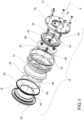
Figure 1 shows, in schematic form, an exploded perspective view of a swivel joint according to a possible embodiment of the present invention; -
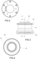
Figure 2 shows, in schematic form, a plan view from below of a swivel joint according to a possible embodiment of the present invention; -
Figure 3 shows, in schematic form, a front view of a swivel joint according to a possible embodiment of the present invention; -
Figure 4 shows, in schematic form, a plan view from above of a swivel joint according to a possible embodiment of the present invention; -
Figure 5 shows, in schematic form, a longitudinal sectional view according to the section plane A-A ofFigure 3 , a swivel joint according to a possible embodiment of the present invention; -
Figure 6 shows a perspective view of a swivel joint according to a possible embodiment of the present invention; -
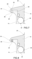
Figures 7 and 8 show, in schematic form, an enlarged portion of the longitudinal section ofFigure 5 , in particular inFigure 7 a detail has been removed; and -
Figure 9 shows, in schematic form, a suspension arm of a device comprising two swivel joints according to a possible embodiment of the present invention. - Elements or parts of elements common to the embodiments described hereinafter will be indicated with the same numerical references.
- In
Figure 1 a swivel joint according to the present invention is indicated with thereference numeral 12. - The swivel joint comprises an external
cylindrical element 14 having a firstexternal connection end 16, an internalcylindrical element 18 having a secondexternal connection end 20. - Bearing means 22 are arranged between the external
cylindrical element 14 and the internalcylindrical element 18 so as to identify a relative rotation axis x between the externalcylindrical element 14 and the internalcylindrical element 18. - Furthermore, the internal
cylindrical element 18 protrudes in a radial direction with respect to the externalcylindrical element 14 making aradial seat 26 for agasket 24, arranged between the externalcylindrical element 14 and the internalcylindrical element 18. - In this way the only portion wherein a metal-to-metal fissure is envisaged is protected by means of the
gasket 24. - Within this discussion the term radial direction signifies a direction that is substantially perpendicular to the direction of the longitudinal axis x.
- According to a possible embodiment, the internal
cylindrical element 18 may protrude in a radial direction with respect to the externalcylindrical element 14 and comprises a firstsurface sealing surface 28 which radially faces asecond sealing surface 30 arranged on the externalcylindrical element 14 to make theradial seat 26 for thegasket 24. - In other words, the internal
cylindrical element 18 protrudes radially in such a way that thegasket 24 may be arranged between a portion of the internalcylindrical element 18 that makes the most external part of theradial seat 26 and a portion of the externalcylindrical element 14 that instead makes a more internal portion of theradial seat 26. - The
gasket 24 may, for example, be made in silicone that is adapted for use with food. - According to a possible embodiment the internal
cylindrical element 18 may be arranged with a head portion 32 that protrudes in a radial direction with respect to the externalcylindrical element 14, being arranged with anend portion 34 protruding in the direction of the axis x on which thefirst sealing surface 28 is made. - The head portion 32 therefore comprises a portion that overlaps externally in a radial direction with respect to the external
cylindrical element 14. - According to a possible embodiment, the
radial seat 26 is arranged with amouth 38 which is tapered so as to retain thegasket 24 in position once the externalcylindrical element 14 and the internalcylindrical element 18 are coupled to each other. - As may be seen in
Figure 8 , once thegasket 24 is inserted into theradial seat 26, any escape of the same from the sameradial seat 26 may be impeded by the tapering which divides the portion of the internalcylindrical element 18 from the portion of the externalcylindrical element 14 which are facing therebetween. - Advantageously, the
tapered mouth 38 is obtained by means of anend portion 34 of the externalcylindrical element 14, for example by means of anappendix 39 protruding in a radial direction towards the longitudinal axis x. - As may be seen from the section of
Figure 5 , the internalcylindrical element 18 may comprise amain body 40 and abottom 42 connected to each other by means ofscrews 44. - According to a possible embodiment, the bearing means 22 may comprise two axially staggered
ball bearings - As may be seen from the section in
Figure 5 , the externalcylindrical element 14 and the internalcylindrical element 18 may be shaped to make the rolling tracks for the balls of theball bearings cylindrical element 14 may be arranged with a portion of reducedinternal diameter 50, and the internalcylindrical element 18 may be made with two portions of increasedexternal diameter diameter portion 50 and the increaseddiameter portions ball bearings - According to one possible embodiment, a first portion of increased
external diameter 52 may be arranged on themain body 40, whilst a second portion of increased external diameter may be arranged on thebottom 42. In this way the mounting of the swivel joint may be facilitated insofar as: - in a first step the balls of the first bearing 46 may be arranged between the first portion of increased
external diameter 52 and the portion of reducedinternal diameter 50; - subsequently the balls of the second bearing 48 are arranged between the portion of reduced
internal diameter 50 and the second portion of increasedexternal diameter 54 that is arranged upon thebottom 42 which is subsequently attached to the main body by screw means 44. - According to a possible alternative embodiment, the at least one bearing may be pre-mounted and arranged within a predetermined seat between the two cylindrical elements.
- In accordance with a possible embodiment, the
swivel joint 12 may comprise afixing element 70, adapted to be connected to the firstexternal connection surface 16, for example by screw means 72. As may be seen inFigure 5 , thefixing element 70 may be arranged on the internal side of asurface 74 and blocked with respect to the firstexternal connection surface 16 by screw means 72 passing through holes arranged on thesurface 74. - As may be seen in the embodiment shown in
Figure 5 , theswivel joint 12 may comprise aconnection gasket 76 adapted to be arranged between the externalcylindrical element 14 and thesurface 74 where the swivel joint is attached. The function of theconnection gasket 76 is that of avoiding the formation of a metal-to-metal fissure between thesurface 74 and the swivel joint for the same reasons mentioned above. - According to a possible embodiment, the connection to the second
external connection end 20 may be accomplished by means of welding. - In alternative embodiments, the connection to the first external connection end 16 and to the second
external connection end 20 may be performed using methods other than those indicated above but known of themselves to a person skilled in the art. - According to one possible embodiment, as may be seen in
Figure 5 and inFigure 1 , between the internal cylindrical element and the external cylindrical element,sealing rings cylindrical element 18 and/or upon the externalcylindrical element 14. - A possible application of the
swivel joint 12 according to the invention is shows inFigure 9 . - The
swivel joint 12 may be used in asuspension arm 64 for a control panel 66 of amachine 68. According to a possible embodiment, the swivel joints 12 may be one arranged between amachine 68 and asuspension arm 64, and one arranged between asuspension arm 64 and a control panel 66. - The swivel joint may furthermore be advantageously used in situations wherein it is necessary to place two elements in rotational connection under special hygienic conditions.
- The advantages that may be achieved with a swivel joint according to the present invention are therefore now apparent.
- Firstly, a swivel joint is made available that may be used in environments wherein a hygiene regulation is envisaged which stipulates that there should be no metal surfaces close together.
- Secondly, a device is made available that whilst suitable for use under particularly demanding hygienic conditions succeeds in being particularly functional.
- A person skilled in the art will be able to make modifications to the embodiments described above and/or substitute described elements with equivalent elements, in order to satisfy particular requirements, without departing from the scope of the accompanying claims.
Claims (11)
- Swivel joint (12) comprising an external cylindrical element (14) having a first external connection end (16), an internal cylindrical element (18) having a second external connection end (20), and bearing means (22) arranged between said external cylindrical element (14) and said internal cylindrical element (18) so as to identify a relative rotation axis (x) ;a gasket (24) being provided between said external cylindrical element (14) and said internal cylindrical element (18);said internal cylindrical element (18) protruding in a radial direction with respect to said external cylindrical element (14) making a radial seat (26) for said gasket (24).
- Swivel joint (12) according to the preceding claim, characterised in that said internal cylindrical element (18) protruding in a radial direction with respect to said external cylindrical element (14) comprises a first sealing surface (28) which radially faces a second sealing surface (30) arranged on said external cylindrical element (14) to make said radial seat (26) for said gasket (24).
- Swivel joint (12) according to the preceding claim, characterised in that said internal cylindrical element (18) is arranged with a head portion (32) protruding in a radial direction with respect to said external cylindrical element (14), said head portion (32) being arranged with an end portion (34) protruding in the direction of the axis (x) on which said first sealing surface (28) is made.
- Swivel joint (12) according to any one of the preceding claims, characterised in that said radial seat (26) is arranged with a tapered mouth (38) adapted to retain the gasket (24) in position.
- Swivel joint (12) according to the preceding claim, characterised in that said tapering (26) is obtained by means of said end portion (34) of said external cylindrical element (14).
- Swivel joint (12) according to any one of the preceding claims, characterised in that said internal cylindrical element (18) comprises a main body (40) and a bottom (42) connected to each other by means of screws (44) .
- Swivel joint (12) according to any one of the preceding claims, characterised in that said bearing means (22) comprise two axially staggered ball bearings (46, 48).
- Swivel joint (12) according to the preceding claim, characterised in that said external cylindrical element (14) and said internal cylindrical element (18) are shaped to make the rolling tracks for the balls of the ball bearings (46, 48), said external cylindrical element (14) being arranged with a portion of reduced internal diameter (50), and said internal cylindrical element (18) being made with two portions of increased external diameter (52, 54) so that between the reduced diameter portion (50) and the increased diameter portions (52, 54) opposing tracks are made in an axial direction on which the balls of the ball bearings (46, 48) can roll.
- Swivel joint (12) according to any one of the preceding claims, characterised in that it comprises a fixing element (70), adapted to be connected to the first external connection surface (16) by screw means (72).
- Swivel joint (12) according to any one of the preceding claims, characterised in that said gasket is made of silicone suitable for food use.
- Suspension arm (64) comprising at least one swivel joint (12) according to any one of the preceding claims, arranged for connection to a machine (68) and/or to a device (66).
Applications Claiming Priority (1)
| Application Number | Priority Date | Filing Date | Title |
|---|---|---|---|
| IT102022000025656A IT202200025656A1 (en) | 2022-12-15 | 2022-12-15 | Swivel joint and suspension arm of a device comprising such a swivel joint |
Publications (2)
| Publication Number | Publication Date |
|---|---|
| EP4386225A1 true EP4386225A1 (en) | 2024-06-19 |
| EP4386225B1 EP4386225B1 (en) | 2025-07-30 |
Family
ID=85381254
Family Applications (1)
| Application Number | Title | Priority Date | Filing Date |
|---|---|---|---|
| EP23214844.5A Active EP4386225B1 (en) | 2022-12-15 | 2023-12-07 | Swivel joint and suspension arm of a device comprising such swivel joint |
Country Status (3)
| Country | Link |
|---|---|
| EP (1) | EP4386225B1 (en) |
| ES (1) | ES3052615T3 (en) |
| IT (1) | IT202200025656A1 (en) |
Citations (4)
| Publication number | Priority date | Publication date | Assignee | Title |
|---|---|---|---|---|
| WO2005010382A1 (en) * | 2003-07-24 | 2005-02-03 | Nsk Ltd. | Rolling bearing unit with rotating speed-detecting device |
| US20140361606A1 (en) * | 2011-09-21 | 2014-12-11 | Shuji Mochinaga | Wheel bearing and bearing device |
| EP3249250B1 (en) | 2016-05-23 | 2019-10-16 | Euro Inox Quality | A rotatable joint for a suspension arm of a control device or similar apparatus |
| CN114017618A (en) * | 2021-11-22 | 2022-02-08 | 无锡巨蟹智能驱动科技有限公司 | Harmonic reducer suitable for pitching driving and used for monitoring cradle head and cradle head |
-
2022
- 2022-12-15 IT IT102022000025656A patent/IT202200025656A1/en unknown
-
2023
- 2023-12-07 ES ES23214844T patent/ES3052615T3/en active Active
- 2023-12-07 EP EP23214844.5A patent/EP4386225B1/en active Active
Patent Citations (4)
| Publication number | Priority date | Publication date | Assignee | Title |
|---|---|---|---|---|
| WO2005010382A1 (en) * | 2003-07-24 | 2005-02-03 | Nsk Ltd. | Rolling bearing unit with rotating speed-detecting device |
| US20140361606A1 (en) * | 2011-09-21 | 2014-12-11 | Shuji Mochinaga | Wheel bearing and bearing device |
| EP3249250B1 (en) | 2016-05-23 | 2019-10-16 | Euro Inox Quality | A rotatable joint for a suspension arm of a control device or similar apparatus |
| CN114017618A (en) * | 2021-11-22 | 2022-02-08 | 无锡巨蟹智能驱动科技有限公司 | Harmonic reducer suitable for pitching driving and used for monitoring cradle head and cradle head |
Also Published As
| Publication number | Publication date |
|---|---|
| ES3052615T3 (en) | 2026-01-12 |
| EP4386225B1 (en) | 2025-07-30 |
| IT202200025656A1 (en) | 2024-06-15 |
Similar Documents
| Publication | Publication Date | Title |
|---|---|---|
| CA2710070C (en) | Valve | |
| US4968156A (en) | Bearing with a magnetic field sensor | |
| US5284398A (en) | Pillow ball joint and method of making the joint | |
| CN115003937B (en) | Sealing components and robots | |
| US4645474A (en) | Sealing device for bearing bushings particularly for universal joints | |
| EP4386225B1 (en) | Swivel joint and suspension arm of a device comprising such swivel joint | |
| JPH07507857A (en) | flexible joint | |
| US5110161A (en) | Means of improving performance of swivelling pressure sealing devices | |
| EP3783248B1 (en) | Process connection with annular moulded seal | |
| EP0264179A2 (en) | Improvements relating to rotary ball valves and ball joints | |
| US6901902B1 (en) | Two-piece valve stem seal | |
| CN117083477A (en) | Sealing components and robots | |
| US4733978A (en) | Contact type flexible seal for bearings | |
| JPS62171522A (en) | Bearing device with seal | |
| US20240209897A1 (en) | Support assembly for moveable shafts | |
| EP0165715A1 (en) | High pressure shaft seal | |
| US20020172442A1 (en) | Bearing arrangement for a shaft bearing | |
| US6736731B2 (en) | Cross member unit for universal joints having a trunnion seal | |
| DE10334896A1 (en) | Sealing arrangement for a shaft comprises a radial shaft sealing ring with a sealing lip, and a shaft surface with a helical profiling leading the medium to be contained back into the sealed space | |
| CN108278367B (en) | Radial Displaceable Seal Assembly for Shafts | |
| CN109139917B (en) | Cross-axle universal joint seal with optimized lip orientation | |
| US20240209896A1 (en) | Support assembly | |
| EP4115503B1 (en) | Electric motor with fan cover and rotor shaft rotatable to fan cover and angle sensor | |
| WO2011031677A1 (en) | Floating wear sleeve assembly for shaft seals | |
| EP2037161B1 (en) | Seal with integrated sensor and seal assembly with such a seal |
Legal Events
| Date | Code | Title | Description |
|---|---|---|---|
| PUAI | Public reference made under article 153(3) epc to a published international application that has entered the european phase |
Free format text: ORIGINAL CODE: 0009012 |
|
| STAA | Information on the status of an ep patent application or granted ep patent |
Free format text: STATUS: THE APPLICATION HAS BEEN PUBLISHED |
|
| AK | Designated contracting states |
Kind code of ref document: A1 Designated state(s): AL AT BE BG CH CY CZ DE DK EE ES FI FR GB GR HR HU IE IS IT LI LT LU LV MC ME MK MT NL NO PL PT RO RS SE SI SK SM TR |
|
| STAA | Information on the status of an ep patent application or granted ep patent |
Free format text: STATUS: REQUEST FOR EXAMINATION WAS MADE |
|
| 17P | Request for examination filed |
Effective date: 20241217 |
|
| GRAP | Despatch of communication of intention to grant a patent |
Free format text: ORIGINAL CODE: EPIDOSNIGR1 |
|
| STAA | Information on the status of an ep patent application or granted ep patent |
Free format text: STATUS: GRANT OF PATENT IS INTENDED |
|
| INTG | Intention to grant announced |
Effective date: 20250220 |
|
| RIN1 | Information on inventor provided before grant (corrected) |
Inventor name: DI LELIO, DIEGO |
|
| GRAS | Grant fee paid |
Free format text: ORIGINAL CODE: EPIDOSNIGR3 |
|
| GRAA | (expected) grant |
Free format text: ORIGINAL CODE: 0009210 |
|
| STAA | Information on the status of an ep patent application or granted ep patent |
Free format text: STATUS: THE PATENT HAS BEEN GRANTED |
|
| AK | Designated contracting states |
Kind code of ref document: B1 Designated state(s): AL AT BE BG CH CY CZ DE DK EE ES FI FR GB GR HR HU IE IS IT LI LT LU LV MC ME MK MT NL NO PL PT RO RS SE SI SK SM TR |
|
| REG | Reference to a national code |
Ref country code: GB Ref legal event code: FG4D |
|
| REG | Reference to a national code |
Ref country code: CH Ref legal event code: EP |
|
| REG | Reference to a national code |
Ref country code: DE Ref legal event code: R096 Ref document number: 602023005251 Country of ref document: DE |
|
| REG | Reference to a national code |
Ref country code: IE Ref legal event code: FG4D |
|
| P01 | Opt-out of the competence of the unified patent court (upc) registered |
Free format text: CASE NUMBER: UPC_APP_9935_4386225/2025 Effective date: 20251014 |
|
| REG | Reference to a national code |
Ref country code: NL Ref legal event code: MP Effective date: 20250730 |
|
| REG | Reference to a national code |
Ref country code: AT Ref legal event code: MK05 Ref document number: 1819210 Country of ref document: AT Kind code of ref document: T Effective date: 20250730 |
|
| PG25 | Lapsed in a contracting state [announced via postgrant information from national office to epo] |
Ref country code: PT Free format text: LAPSE BECAUSE OF FAILURE TO SUBMIT A TRANSLATION OF THE DESCRIPTION OR TO PAY THE FEE WITHIN THE PRESCRIBED TIME-LIMIT Effective date: 20251202 |
|
| PG25 | Lapsed in a contracting state [announced via postgrant information from national office to epo] |
Ref country code: IS Free format text: LAPSE BECAUSE OF FAILURE TO SUBMIT A TRANSLATION OF THE DESCRIPTION OR TO PAY THE FEE WITHIN THE PRESCRIBED TIME-LIMIT Effective date: 20251130 |
|
| PG25 | Lapsed in a contracting state [announced via postgrant information from national office to epo] |
Ref country code: NO Free format text: LAPSE BECAUSE OF FAILURE TO SUBMIT A TRANSLATION OF THE DESCRIPTION OR TO PAY THE FEE WITHIN THE PRESCRIBED TIME-LIMIT Effective date: 20251030 |
|
| REG | Reference to a national code |
Ref country code: ES Ref legal event code: FG2A Ref document number: 3052615 Country of ref document: ES Kind code of ref document: T3 Effective date: 20260112 Ref country code: LT Ref legal event code: MG9D |
|
| PG25 | Lapsed in a contracting state [announced via postgrant information from national office to epo] |
Ref country code: AT Free format text: LAPSE BECAUSE OF FAILURE TO SUBMIT A TRANSLATION OF THE DESCRIPTION OR TO PAY THE FEE WITHIN THE PRESCRIBED TIME-LIMIT Effective date: 20250730 |
|
| PG25 | Lapsed in a contracting state [announced via postgrant information from national office to epo] |
Ref country code: FI Free format text: LAPSE BECAUSE OF FAILURE TO SUBMIT A TRANSLATION OF THE DESCRIPTION OR TO PAY THE FEE WITHIN THE PRESCRIBED TIME-LIMIT Effective date: 20250730 |
|
| PG25 | Lapsed in a contracting state [announced via postgrant information from national office to epo] |
Ref country code: NL Free format text: LAPSE BECAUSE OF FAILURE TO SUBMIT A TRANSLATION OF THE DESCRIPTION OR TO PAY THE FEE WITHIN THE PRESCRIBED TIME-LIMIT Effective date: 20250730 Ref country code: HR Free format text: LAPSE BECAUSE OF FAILURE TO SUBMIT A TRANSLATION OF THE DESCRIPTION OR TO PAY THE FEE WITHIN THE PRESCRIBED TIME-LIMIT Effective date: 20250730 |
|
| PGFP | Annual fee paid to national office [announced via postgrant information from national office to epo] |
Ref country code: FR Payment date: 20251128 Year of fee payment: 3 |
|
| PG25 | Lapsed in a contracting state [announced via postgrant information from national office to epo] |
Ref country code: GR Free format text: LAPSE BECAUSE OF FAILURE TO SUBMIT A TRANSLATION OF THE DESCRIPTION OR TO PAY THE FEE WITHIN THE PRESCRIBED TIME-LIMIT Effective date: 20251031 |
|
| PG25 | Lapsed in a contracting state [announced via postgrant information from national office to epo] |
Ref country code: SE Free format text: LAPSE BECAUSE OF FAILURE TO SUBMIT A TRANSLATION OF THE DESCRIPTION OR TO PAY THE FEE WITHIN THE PRESCRIBED TIME-LIMIT Effective date: 20250730 |
|
| PG25 | Lapsed in a contracting state [announced via postgrant information from national office to epo] |
Ref country code: LV Free format text: LAPSE BECAUSE OF FAILURE TO SUBMIT A TRANSLATION OF THE DESCRIPTION OR TO PAY THE FEE WITHIN THE PRESCRIBED TIME-LIMIT Effective date: 20250730 |
|
| PG25 | Lapsed in a contracting state [announced via postgrant information from national office to epo] |
Ref country code: BG Free format text: LAPSE BECAUSE OF FAILURE TO SUBMIT A TRANSLATION OF THE DESCRIPTION OR TO PAY THE FEE WITHIN THE PRESCRIBED TIME-LIMIT Effective date: 20250730 Ref country code: PL Free format text: LAPSE BECAUSE OF FAILURE TO SUBMIT A TRANSLATION OF THE DESCRIPTION OR TO PAY THE FEE WITHIN THE PRESCRIBED TIME-LIMIT Effective date: 20250730 |
|
| PG25 | Lapsed in a contracting state [announced via postgrant information from national office to epo] |
Ref country code: RS Free format text: LAPSE BECAUSE OF FAILURE TO SUBMIT A TRANSLATION OF THE DESCRIPTION OR TO PAY THE FEE WITHIN THE PRESCRIBED TIME-LIMIT Effective date: 20251030 |
|
| PG25 | Lapsed in a contracting state [announced via postgrant information from national office to epo] |
Ref country code: RO Free format text: LAPSE BECAUSE OF FAILURE TO SUBMIT A TRANSLATION OF THE DESCRIPTION OR TO PAY THE FEE WITHIN THE PRESCRIBED TIME-LIMIT Effective date: 20250730 |
|
| PG25 | Lapsed in a contracting state [announced via postgrant information from national office to epo] |
Ref country code: SM Free format text: LAPSE BECAUSE OF FAILURE TO SUBMIT A TRANSLATION OF THE DESCRIPTION OR TO PAY THE FEE WITHIN THE PRESCRIBED TIME-LIMIT Effective date: 20250730 |
|
| PGFP | Annual fee paid to national office [announced via postgrant information from national office to epo] |
Ref country code: ES Payment date: 20260102 Year of fee payment: 3 |
|
| PG25 | Lapsed in a contracting state [announced via postgrant information from national office to epo] |
Ref country code: DK Free format text: LAPSE BECAUSE OF FAILURE TO SUBMIT A TRANSLATION OF THE DESCRIPTION OR TO PAY THE FEE WITHIN THE PRESCRIBED TIME-LIMIT Effective date: 20250730 |
|
| PGFP | Annual fee paid to national office [announced via postgrant information from national office to epo] |
Ref country code: DE Payment date: 20251222 Year of fee payment: 3 |
|
| PGFP | Annual fee paid to national office [announced via postgrant information from national office to epo] |
Ref country code: IT Payment date: 20251231 Year of fee payment: 3 |
|
| PG25 | Lapsed in a contracting state [announced via postgrant information from national office to epo] |
Ref country code: CZ Free format text: LAPSE BECAUSE OF FAILURE TO SUBMIT A TRANSLATION OF THE DESCRIPTION OR TO PAY THE FEE WITHIN THE PRESCRIBED TIME-LIMIT Effective date: 20250730 |
|
| PG25 | Lapsed in a contracting state [announced via postgrant information from national office to epo] |
Ref country code: SK Free format text: LAPSE BECAUSE OF FAILURE TO SUBMIT A TRANSLATION OF THE DESCRIPTION OR TO PAY THE FEE WITHIN THE PRESCRIBED TIME-LIMIT Effective date: 20250730 Ref country code: EE Free format text: LAPSE BECAUSE OF FAILURE TO SUBMIT A TRANSLATION OF THE DESCRIPTION OR TO PAY THE FEE WITHIN THE PRESCRIBED TIME-LIMIT Effective date: 20250730 |
|
| REG | Reference to a national code |
Ref country code: DE Ref legal event code: R097 Ref document number: 602023005251 Country of ref document: DE |
|
| PLBE | No opposition filed within time limit |
Free format text: ORIGINAL CODE: 0009261 |
|
| STAA | Information on the status of an ep patent application or granted ep patent |
Free format text: STATUS: NO OPPOSITION FILED WITHIN TIME LIMIT |
|
| REG | Reference to a national code |
Ref country code: CH Ref legal event code: L10 Free format text: ST27 STATUS EVENT CODE: U-0-0-L10-L00 (AS PROVIDED BY THE NATIONAL OFFICE) Effective date: 20260611 |
|
| PG25 | Lapsed in a contracting state [announced via postgrant information from national office to epo] |
Ref country code: LT Free format text: LAPSE BECAUSE OF FAILURE TO SUBMIT A TRANSLATION OF THE DESCRIPTION OR TO PAY THE FEE WITHIN THE PRESCRIBED TIME-LIMIT Effective date: 20250730 |
|
| PG25 | Lapsed in a contracting state [announced via postgrant information from national office to epo] |
Ref country code: MC Free format text: LAPSE BECAUSE OF FAILURE TO SUBMIT A TRANSLATION OF THE DESCRIPTION OR TO PAY THE FEE WITHIN THE PRESCRIBED TIME-LIMIT Effective date: 20250730 |
|
| 26N | No opposition filed |
Effective date: 20260501 |