EP4386193A1 - Thermal management system for gas turbine engine - Google Patents
Thermal management system for gas turbine engine Download PDFInfo
- Publication number
- EP4386193A1 EP4386193A1 EP23212942.9A EP23212942A EP4386193A1 EP 4386193 A1 EP4386193 A1 EP 4386193A1 EP 23212942 A EP23212942 A EP 23212942A EP 4386193 A1 EP4386193 A1 EP 4386193A1
- Authority
- EP
- European Patent Office
- Prior art keywords
- removable
- outer cowl
- rotational axis
- shims
- bypass
- Prior art date
- Legal status (The legal status is an assumption and is not a legal conclusion. Google has not performed a legal analysis and makes no representation as to the accuracy of the status listed.)
- Granted
Links
Images






Classifications
-
- F—MECHANICAL ENGINEERING; LIGHTING; HEATING; WEAPONS; BLASTING
- F02—COMBUSTION ENGINES; HOT-GAS OR COMBUSTION-PRODUCT ENGINE PLANTS
- F02K—JET-PROPULSION PLANTS
- F02K3/00—Plants including a gas turbine driving a compressor or a ducted fan
- F02K3/08—Plants including a gas turbine driving a compressor or a ducted fan with supplementary heating of the working fluid; Control thereof
- F02K3/105—Heating the by-pass flow
- F02K3/115—Heating the by-pass flow by means of indirect heat exchange
-
- F—MECHANICAL ENGINEERING; LIGHTING; HEATING; WEAPONS; BLASTING
- F02—COMBUSTION ENGINES; HOT-GAS OR COMBUSTION-PRODUCT ENGINE PLANTS
- F02C—GAS-TURBINE PLANTS; AIR INTAKES FOR JET-PROPULSION PLANTS; CONTROLLING FUEL SUPPLY IN AIR-BREATHING JET-PROPULSION PLANTS
- F02C7/00—Features, components parts, details or accessories, not provided for in, or of interest apart form groups F02C1/00 - F02C6/00; Air intakes for jet-propulsion plants
- F02C7/12—Cooling of plants
- F02C7/16—Cooling of plants characterised by cooling medium
- F02C7/18—Cooling of plants characterised by cooling medium the medium being gaseous, e.g. air
-
- F—MECHANICAL ENGINEERING; LIGHTING; HEATING; WEAPONS; BLASTING
- F05—INDEXING SCHEMES RELATING TO ENGINES OR PUMPS IN VARIOUS SUBCLASSES OF CLASSES F01-F04
- F05D—INDEXING SCHEME FOR ASPECTS RELATING TO NON-POSITIVE-DISPLACEMENT MACHINES OR ENGINES, GAS-TURBINES OR JET-PROPULSION PLANTS
- F05D2240/00—Components
- F05D2240/10—Stators
- F05D2240/14—Casings or housings protecting or supporting assemblies within
-
- F—MECHANICAL ENGINEERING; LIGHTING; HEATING; WEAPONS; BLASTING
- F05—INDEXING SCHEMES RELATING TO ENGINES OR PUMPS IN VARIOUS SUBCLASSES OF CLASSES F01-F04
- F05D—INDEXING SCHEME FOR ASPECTS RELATING TO NON-POSITIVE-DISPLACEMENT MACHINES OR ENGINES, GAS-TURBINES OR JET-PROPULSION PLANTS
- F05D2260/00—Function
- F05D2260/20—Heat transfer, e.g. cooling
- F05D2260/213—Heat transfer, e.g. cooling by the provision of a heat exchanger within the cooling circuit
-
- F—MECHANICAL ENGINEERING; LIGHTING; HEATING; WEAPONS; BLASTING
- F05—INDEXING SCHEMES RELATING TO ENGINES OR PUMPS IN VARIOUS SUBCLASSES OF CLASSES F01-F04
- F05D—INDEXING SCHEME FOR ASPECTS RELATING TO NON-POSITIVE-DISPLACEMENT MACHINES OR ENGINES, GAS-TURBINES OR JET-PROPULSION PLANTS
- F05D2260/00—Function
- F05D2260/30—Retaining components in desired mutual position
- F05D2260/31—Retaining bolts or nuts
-
- F—MECHANICAL ENGINEERING; LIGHTING; HEATING; WEAPONS; BLASTING
- F05—INDEXING SCHEMES RELATING TO ENGINES OR PUMPS IN VARIOUS SUBCLASSES OF CLASSES F01-F04
- F05D—INDEXING SCHEME FOR ASPECTS RELATING TO NON-POSITIVE-DISPLACEMENT MACHINES OR ENGINES, GAS-TURBINES OR JET-PROPULSION PLANTS
- F05D2260/00—Function
- F05D2260/60—Fluid transfer
- F05D2260/606—Bypassing the fluid
Definitions
- the present disclosure generally relates to a thermal management system for a gas turbine engine and a method for thermal management of the gas turbine engine.
- Thermal management systems for gas turbine engines may manage heat generated and rejected by the gas turbine engine during operation to ensure that all engine fluids within the gas turbine engine are maintained at safe and effective temperatures at all times.
- Heat rejection requirements for the gas turbine engine may depend on operational conditions as well as design assumptions, which are characterised by uncertainties during operation of the gas turbine engine. Such uncertainties may vary throughout a design process of the gas turbine engine. Further, the operational conditions may change during a service life of the gas turbine engine, either due to environmental conditions, degradation, and /or deviation in an operational scope (e.g., use of sustainable aviation fuel). As a consequence, actual heat rejection may be different from a required demand, leading to incompatibility and/or operation of the gas turbine engine beyond its intended envelope, or even restricted operation.
- the unknown uncertainties may still dominate, resulting in a system that is under-sized for a required duty cycle.
- a possible reason for this under-sizing may be an extension in an operational envelope of the gas turbine engine or the associated equipment (e.g., a gearbox, an auxiliary system, such as power electronics, etc.). Such requirements may appear later during an engine design process and/or in-service after the engine design process is complete.
- a thermal management system for a gas turbine engine having a principal rotational axis, an engine core, and a nacelle.
- the thermal management system includes a bypass inner wall circumferentially surrounding the engine core around the principal rotational axis and extending along the principal rotational axis.
- the bypass inner wall is radially disposed between the engine core and the nacelle relative to the principal rotational axis, such that a main bypass duct is defined between the bypass inner wall and the nacelle.
- the thermal management system further includes an outer cowl circumferentially surrounding and radially spaced apart from the bypass inner wall relative to the principal rotational axis. The outer cowl extends along the principal rotational axis between an inlet end and an outlet end.
- the outer cowl is disposed within the main bypass duct.
- the thermal management system further includes a plurality of inlet vanes extending from the bypass inner wall towards the outer cowl and disposed proximal to the inlet end of the outer cowl. The plurality of inlet vanes are circumferentially spaced apart from each other relative to the principal rotational axis.
- the thermal management system further includes a plurality of outlet vanes extending from the bypass inner wall towards the outer cowl and disposed proximal to the outlet end of the outer cowl. The plurality of outlet vanes are circumferentially spaced apart from each other relative to the principal rotational axis.
- the thermal management system further includes a heat exchanger extending from the bypass inner wall towards the outer cowl and axially disposed between the inlet end and the outlet end relative to the principal rotational axis.
- the thermal management system further includes a plurality of first removable shims corresponding to the plurality of inlet vanes. Each first removable shim from the plurality of first removable shims extends between and engages the outer cowl and a corresponding inlet vane from the plurality of inlet vanes.
- the thermal management system further includes a plurality of second removable shims corresponding to the plurality of outlet vanes.
- Each second removable shim from the plurality of second removable shims extends between and engages the outer cowl and a corresponding outlet vane from the plurality of outlet vanes.
- the thermal management system further includes a third removable shim extending between and engaging the heat exchanger and the outer cowl.
- the third removable shim circumferentially extends around the principal rotational axis.
- the plurality of first removable shims, the plurality of second removable shims, and the third removable shim may allow the outer cowl to be positionally adjusted relative to the bypass inner wall.
- the plurality of first removable shims, the plurality of second removable shims, and the third removable shim may allow the outer cowl to be moved in an axial and/or a radial direction relative to the principal rotational axis, thereby increasing or decreasing geometric areas at the inlet end and the outlet end of the outer cowl. This may increase or decrease air flowing through the heat exchanger, thereby allowing a performance of the thermal management system to be adjusted based on updated operational requirements of the gas turbine engine after a design of the gas turbine engine has been fixed.
- the plurality of first removable shims and the plurality of second removable shims may be located at discrete circumferential positions around the principal rotational axis, thereby allowing the air flow through the heat exchanger without significant resistance to the flow of air.
- the third removable shim may be removable such that the heat exchanger remains engaged with the outer cowl as the outer cowl is adjusted relative to the bypass inner wall. In some extreme circumstances, the third removable shim may be used to shroud a portion of the heat exchanger, thereby further varying the performance of the thermal management system.
- the plurality of first removable shims, the plurality of second removable shims, and the third removable shim may be manufactured in groups of different radial thicknesses, thereby accommodating various settings of a performance of the heat exchanger.
- the introduction of the plurality of first removable shims, the plurality of second removable shims, and the third removable shim may not affect attachment mechanisms for the heat exchanger and anchoring of a supporting structure for the outer cowl.
- the plurality of first removable shims, the plurality of second removable shims, and the third removable shim may become a part of the supporting structure of the outer cowl.
- the existing gas turbine engines may not require significant modifications to accommodate the plurality of first removable shims, the plurality of second removable shims, and the third removable shim.
- a relative movement of the inlet end and the outlet end may be used to alter interactions with adjacent components and hardware, if interactions appear dominant during development and/or in-service operation of the gas turbine engine after a basic design of the gas turbine engine is fixed.
- the plurality of first removable shims, the plurality of second removable shims, and the third removable shim may provide a simple and a cost-effective solution for varying the performance of the thermal management system. This may mitigate the need for an over-sized thermal management system for accommodating all combinations of known and unknown uncertainties since the performance of the thermal management system of the present disclosure may be adjusted based on the updated operational requirements of the gas turbine engine. This may further reduce a weight and a size of the gas turbine engine, thereby improving an overall efficiency of the gas turbine engine. Further, maintenance requirements of the thermal management system may be reduced due to a simple design of the plurality of first removable shims, the plurality of second removable shims, and the third removable shim, thereby reducing a downtime of the gas turbine engine.
- the performance of the thermal management system is not adjusted based on multiple components forming the outer cowl which would have otherwise resulted in excessive costs associated with multiple moulds / pressings.
- the proposed solution includes use of additional shims for adjusting the performance of the thermal management system as the shims may be designed and manufactured at reduced cost.
- the bypass inner wall includes a first bypass surface facing the outer cowl and substantially parallel to the principal rotational axis. In some embodiments, the bypass inner wall further includes a second bypass surface extending from the first bypass surface and inclined obliquely relative to the principal rotational axis away from the outer cowl. In some embodiments, the bypass inner wall further includes a third bypass surface extending from and inclined obliquely to the second bypass surface. The third bypass surface is further inclined obliquely relative to the principal rotational axis towards the outer cowl. In some embodiments, the bypass inner wall further includes a fourth bypass surface extending from the third bypass surface and substantially parallel to the principal rotational axis.
- the first bypass surface and the fourth bypass surface may allow the air flow to enter and exit a duct defined between the outer cowl and the bypass inner wall substantially parallel to the principal rotational axis.
- the heat exchanger may be inclined relative to the principal rotational axis.
- the second and third bypass surfaces may be inclined to accommodate the heat exchanger (which may be inclined) between the outer cowl and the bypass inner wall.
- the outer cowl includes a first cowl surface facing the bypass inner wall and substantially parallel to the principal rotational axis. In some embodiments, the outer cowl further includes a second cowl surface facing the bypass inner wall and substantially parallel to the principal rotational axis. The second cowl surface is axially and radially spaced apart from the first cowl surface relative to the principal rotational axis. In some embodiments, the outer cowl further includes a third cowl surface extending between the first cowl surface and the second cowl surface. The third cowl surface is inclined obliquely relative to the principal rotational axis and substantially parallel to the third bypass surface of the bypass inner wall. The heat exchanger extends between the third cowl surface and the third bypass surface.
- the first cowl surface and the second cowl surface may allow the air flow to enter and exit the duct defined between the outer cowl and the bypass inner wall substantially parallel to the principal rotational axis.
- the third cowl surface may be inclined obliquely relative to the principal rotational axis to accommodate the heat exchanger (in an inclined configuration) between the outer cowl and the bypass inner wall.
- the outer cowl further includes a plurality of panels disposed circumferentially adjacent to each other relative to the principal rotational axis. Each panel from the plurality of panels defines a first circumferential edge and a second circumferential edge opposite to the first circumferential edge. Each panel includes a recess circumferentially extending partially from the second circumferential edge towards the first circumferential edge.
- the outer cowl further includes a plurality of elastic lips corresponding to the plurality of panels. Each of the plurality of elastic lips circumferentially extends from the first circumferential edge of a corresponding panel towards the second circumferential edge of an adjacent panel from the plurality of panels. Each of the plurality of elastic lips is slidably and at least partially received on the recess of the adjacent panel.
- the plurality of elastic lips may deflect to accommodate any gaps generated between the plurality of panels due to radially inward or outward movement of the plurality of panels at the inlet end or the outlet end of the outer cowl.
- the plurality of elastic lips may be provided at circumferentially adjoining interfaces between the plurality of panels, i.e., between the first and second circumferential edges.
- the plurality of elastic lips may ensure a continuous and smooth surface in a circumferential direction, thereby allowing conformance at various circumferential locations of the outer cowl. Thus, any mismatch between the plurality of panels due to the movement of the outer cowl may be mitigated.
- the thermal management system further includes a plurality of mechanical attachments corresponding to the plurality of elastic lips.
- Each of the plurality of mechanical attachments couples a corresponding elastic lip from the plurality of elastic lips to the recess of the adjacent panel.
- Each of the plurality of mechanical attachments e.g., a bolt movable within a slot of the adjacent panel
- the thermal management system further includes a plurality of first countersunk bolts corresponding to the plurality of first removable shims.
- Each of the plurality of first countersunk bolts extends through a corresponding first removable shim from the plurality of first removable shims and removably couples the corresponding first removable shim to each of the outer cowl and the corresponding inlet vane.
- the plurality of first countersunk bolts may removably couple the corresponding first removable shim to each of the outer cowl and the corresponding inlet vane, thereby allowing the corresponding first removable shim to be replaced or removed as per updated operational requirements of the gas turbine engine.
- the thermal management system further includes a plurality of second countersunk bolts corresponding to the plurality of second removable shims.
- Each of the second countersunk bolts extends through a corresponding second removable shim from the plurality of second removable shims and removably couples the corresponding second removable shim to each of the outer cowl and the corresponding outlet vane.
- the plurality of second countersunk bolts may removably couple the corresponding second removable shim to each of the outer cowl and the corresponding outlet vane, thereby allowing the corresponding second removable shim to be replaced or removed as per updated operational requirements of the gas turbine engine.
- the thermal management system further includes a plurality of first replacement shims corresponding to the plurality of first removable shims.
- Each of the plurality of first replacement shims is removably disposed between and engages the outer cowl and the corresponding inlet vane after removal of the corresponding first removable shim.
- the plurality of first replacement shims may allow the outer cowl to be positionally adjusted relative to the bypass inner wall by replacing the plurality of first removable shims with the plurality of first replacement shims.
- each of the plurality first replacement shims includes a thickness different from a thickness of each of the plurality of first removable shims.
- the radial distance between the inlet end of the outer cowl and the bypass inner wall may be increased or decreased by replacing the plurality of first removable shims with the plurality of first replacement shims, thereby altering the performance of the thermal management system based on updated operational requirements of the gas turbine engine.
- the thermal management system further includes a plurality of second replacement shims corresponding to the plurality of second removable shims.
- Each of the plurality of second replacement shims is removably disposed between and engages the outer cowl and the corresponding outlet vane after removal of the corresponding second removable shim.
- the plurality of second replacement shims may allow the outer cowl to be positionally adjusted relative to the bypass inner wall by replacing the plurality of second removable shims with the plurality of second replacement shims.
- each of the plurality second replacement shims includes a thickness different from a thickness of each of the plurality of second removable shims.
- the radial distance between the outlet end of the outer cowl and the bypass inner wall may be increased or decreased by replacing the plurality of second removable shims with the plurality of second replacement shims, thereby altering the performance of the thermal management system based on updated operational requirements of the gas turbine engine.
- the thermal management system further includes a third replacement shim.
- This shim is removably disposed between and engages the heat exchanger and the outer cowl after removal of the third removable shim.
- the third replacement shim may replace the third removable shim such that the heat exchanger remains engaged with the outer cowl as the outer cowl is positionally adjusted relative to the bypass inner wall.
- a thickness of the third replacement shim may be different from a thickness of the third removable shim.
- a gas turbine engine incudes a principal rotational axis and an engine core extending along the principal rotational axis.
- the gas turbine engine further incudes a nacelle circumferentially surrounding the engine core around the principal rotational axis.
- the gas turbine engine further incudes the thermal management system of the first aspect.
- the bypass inner wall of the thermal management system circumferentially surrounds the engine core around the principal rotational axis and extends along the principal rotational axis.
- the bypass inner wall is radially disposed between the engine core and the nacelle relative to the principal rotational axis, such that a main bypass duct is defined between the bypass inner wall and the nacelle.
- a method for thermal management of a gas turbine engine having a principal rotational axis, an engine core, and a nacelle.
- the method includes providing a bypass inner wall circumferentially surrounding the engine core around the principal rotational axis and extending along the principal rotational axis.
- the bypass inner wall is radially disposed between the engine core and the nacelle relative to the principal rotational axis, such that a main bypass duct is defined between the bypass inner wall and the nacelle.
- the method further includes providing an outer cowl circumferentially surrounding and radially spaced apart from the bypass inner wall relative to the principal rotational axis.
- the outer cowl extends along the principal rotational axis between an inlet end and an outlet end.
- the outer cowl is disposed within the main bypass duct.
- the method further includes providing a plurality of inlet vanes extending from the bypass inner wall towards the outer cowl and disposed proximal to the inlet end of the outer cowl.
- the plurality of inlet vanes are circumferentially spaced apart from each other relative to the principal rotational axis.
- the method further includes providing a plurality of outlet vanes extending from the bypass inner wall towards the outer cowl and disposed proximal to the outlet end of the outer cowl.
- the plurality of outlet vanes are circumferentially spaced apart from each other relative to the principal rotational axis.
- the method further includes providing a heat exchanger extending from the bypass inner wall towards the outer cowl and axially disposed between the inlet end and the outlet end relative to the principal rotational axis.
- the method further includes providing a plurality of first removable shims corresponding to the plurality of inlet vanes. Each first removable shim extends between and engages the outer cowl and a corresponding inlet vane from the plurality of inlet vanes.
- the method further includes providing a plurality of second removable shims corresponding to the plurality of outlet vanes. Each second removable shim extends between and engages the outer cowl and a corresponding outlet vane from the plurality of outlet vanes.
- the method further includes providing a third removable shim extending between and engaging the heat exchanger and the outer cowl.
- the third removable shim circumferentially extends around the principal rotational axis.
- the method further includes positionally adjusting the outer cowl relative to the bypass inner wall by: removing each of the plurality of first removable shims from between the corresponding inlet vane and the outer cowl; removing each of the plurality of second removable shims from between the corresponding outlet vane and the outer cowl; and removing the third removable shim from between the heat exchanger and the outer cowl.
- the method further includes providing a plurality of first replacement shims corresponding to the plurality of first removable shims.
- Each of the plurality first replacement shims includes a thickness different from a thickness of each of the plurality of first removable shims.
- the method further includes removably disposing each of the plurality of first replacement shims between the outer cowl and the corresponding inlet vane after removal of the corresponding first removable shim, such that each of the plurality of first replacement shims engages each of the outer cowl and the corresponding inlet vane.
- the method further includes providing a plurality of second replacement shims corresponding to the plurality of second removable shims.
- Each of the plurality second replacement shims includes a thickness different from a thickness of each of the plurality of second removable shims.
- the method further includes removably disposing each of the plurality of second replacement shims between the outer cowl and the corresponding outlet vane after removal of the corresponding second removable shim, such that each of the plurality of second replacement shims engages each of the outer cowl and the corresponding outlet vane.
- the method further includes removably disposing a third replacement shim between the heat exchanger and the outer cowl after removal of the third removable shim, such that the third replacement shim engages each of the heat exchanger and the outer cowl.
- a thickness of the third replacement shim may be different from a thickness of the third removable shim.
- Such a gas turbine engine may comprise an engine core comprising a turbine, a combustor, a compressor, and a core shaft connecting the turbine to the compressor.
- a gas turbine engine may comprise a fan (having fan blades) located upstream of the engine core.
- the gas turbine engine may comprise a gearbox that receives an input from the core shaft and outputs drive to the fan so as to drive the fan at a lower rotational speed than the core shaft.
- the input to the gearbox may be directly from the core shaft, or indirectly from the core shaft, for example via a spur shaft and/or gear.
- the core shaft may rigidly connect the turbine and the compressor, such that the turbine and compressor rotate at the same speed (with the fan rotating at a lower speed).
- the gas turbine engine as described and/or claimed herein may have any suitable general architecture.
- the gas turbine engine may have any desired number of shafts that connect turbines and compressors, for example, one, two, or three shafts.
- the turbine connected to the core shaft may be a first turbine
- the compressor connected to the core shaft may be a first compressor
- the core shaft may be a first core shaft.
- the engine core may further comprise a second turbine, a second compressor, and a second core shaft connecting the second turbine to the second compressor.
- the second turbine, second compressor, and second core shaft may be arranged to rotate at a higher rotational speed than the first core shaft.
- the second compressor may be positioned axially downstream of the first compressor.
- the second compressor may be arranged to receive (for example directly receive, for example via a generally annular duct) flow from the first compressor.
- a combustor may be provided axially downstream of the fan and compressor(s).
- the combustor may be directly downstream of (for example at the exit of) the second compressor, where a second compressor is provided.
- the flow at the exit to the combustor may be provided to the inlet of the second turbine, where a second turbine is provided.
- the combustor may be provided upstream of the turbine(s).
- each compressor may comprise any number of stages, for example multiple stages.
- Each stage may comprise a row of rotor blades and a row of stator vanes, which may be variable stator vanes (in that their angle of incidence may be variable).
- the row of rotor blades and the row of stator vanes may be axially offset from each other.
- each turbine may comprise any number of stages, for example multiple stages.
- Each stage may comprise a row of rotor blades and a row of stator vanes.
- the row of rotor blades and the row of stator vanes may be axially offset from each other.
- Gas turbine engines in accordance with the present disclosure may have any desired bypass ratio, where the bypass ratio is defined as the ratio of the mass flow rate of the flow through the main bypass duct to the mass flow rate of the flow through the core at cruise conditions.
- the bypass ratio may be greater than (or on the order of) any of the following: 10, 10.5, 11, 11.5, 12, 12.5, 13, 13.5, 14, 14.5, 15, 15.5, 16, 16.5, 17, 17.5, 18, 18.5, 19, 19.5 or20.
- the bypass ratio may be in an inclusive range bounded by any two of the values in the previous sentence (i.e. the values may form upper or lower bounds), for example in the range of from 12 to 16, 13 to 15, or 13 to 14.
- the main bypass duct may be substantially annular.
- the main bypass duct may be radially outside the engine core.
- the radially outer surface of the main bypass duct may be defined by a nacelle and/or a fan case.
- Specific thrust of an engine may be defined as the net thrust of the engine divided by the total mass flow through the engine. At cruise conditions, the specific thrust of an engine described and/or claimed herein may be less than (or on the order of) any of the following: 110 Nkg -1 s, 105 Nkg -1 s, 100 Nkg -1 s, 95 Nkg -1 s, 90 Nkg -1 s, 85 Nkg -1 s or 80 Nkg-'s.
- the specific thrust may be in an inclusive range bounded by any two of the values in the previous sentence (i.e., the values may form upper or lower bounds), for example in the range of from 80 Nkg-'s to 100 Nkg -1 s, or 85 Nkg -1 s to 95 Nkg-'s.
- Such engines may be particularly efficient in comparison with conventional gas turbine engines.
- a fan blade and/or aerofoil portion of a fan blade described and/or claimed herein may be manufactured from any suitable material or combination of materials.
- at least a part of the fan blade and/or aerofoil may be manufactured at least in part from a composite, for example a metal matrix composite and/or an organic matrix composite, such as carbon fibre.
- the fan of a gas turbine as described and/or claimed herein may have any desired number of fan blades, for example 14, 16, 18, 20, 22, 24 or 26 fan blades.
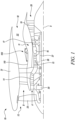
- FIG. 1 illustrates a gas turbine engine 10 having a principal rotational axis 9.
- the gas turbine engine 10 comprises an air intake 12 and a propulsive fan 23 that generates two airflows: a core airflow A and a bypass airflow B.
- the gas turbine engine 10 comprises an engine core 11 extending along the principal rotational axis 9 and receiving the core airflow A.
- the engine core 11 comprises, in axial flow series, a low pressure compressor 14, a high pressure compressor 15, combustion equipment 16, a high pressure turbine 17, a low pressure turbine 19, and a core exhaust nozzle 20.
- the gas turbine engine 10 further comprises a nacelle 21 circumferentially surrounding the engine core 11 around the principal rotational axis 9 and defining a main bypass duct 22 and a bypass exhaust nozzle 18.
- the bypass airflow B flows through the main bypass duct 22.
- the fan 23 is attached to and driven by the low pressure turbine 19 via a shaft 26 and an epicyclic gearbox 30.
- the core airflow A is accelerated and compressed by the low pressure compressor 14 and directed into the high pressure compressor 15 where further compression takes place.
- the compressed air exhausted from the high pressure compressor 15 is directed into the combustion equipment 16 where it is mixed with fuel and the mixture is combusted.
- the resultant hot combustion products then expand through, and thereby drive, the high pressure and low pressure turbines 17, 19 before being exhausted through the core exhaust nozzle 20 to provide some propulsive thrust.
- the high pressure turbine 17 drives the high pressure compressor 15 by a suitable interconnecting shaft 27.
- the fan 23 generally provides the majority of the propulsive thrust.
- the epicyclic gearbox 30 is a reduction gearbox.
- the gas turbine engine 10 further includes a thermal management system 100.
- the thermal management system 100 may manage heat generated and rejected by the gas turbine engine 10 during operation to ensure that all engine fluids (or fluids from associated equipment) within the gas turbine engine 10 are maintained at safe and effective temperatures at all times.
- the thermal management system 100 may be disposed in fluid communication with the main bypass duct 22 and may receive at least a portion of the bypass airflow B from the main bypass duct 22.
- the bypass airflow B may be utilized in the thermal management system 100 for cooling the engine fluids.
- FIG. 2 An exemplary arrangement for a geared fan gas turbine engine 10 is shown in Figure 2 .
- the low pressure turbine 19 (see Figure 1 ) drives the shaft 26, which is coupled to a sun wheel, or a sun gear 28 of the epicyclic gearbox 30.
- Radially outwardly of the sun gear 28 and intermeshing therewith is a plurality of planet gears 32 that are coupled together by a planet carrier 34.
- the planet carrier 34 constrains the planet gears 32 to process around the sun gear 28 in synchronicity whilst enabling each planet gear 32 to rotate about its own axis.
- the planet carrier 34 is coupled via linkages 36 to the fan 23 in order to drive its rotation about the principal rotational axis 9.
- an annulus or ring gear 38 Radially outwardly of the planet gears 32 and intermeshing therewith is an annulus or ring gear 38 that is coupled, via linkages 40, to a stationary supporting structure 24.
- low pressure turbine and “low pressure compressor” as used herein may be taken to mean the lowest pressure turbine stages and lowest pressure compressor stages (i.e., not including the fan 23), respectively, and/or the turbine and compressor stages that are connected together by the shaft 26 with the lowest rotational speed in the engine (i.e., not including the gearbox output shaft that drives the fan 23).
- the "low pressure turbine” and “low pressure compressor” referred to herein may alternatively be known as the “intermediate pressure turbine” and “intermediate pressure compressor”. Where such alternative nomenclature is used, the fan 23 may be a first, or lowest pressure, compression stage.
- the present disclosure extends to a gas turbine engine having any arrangement of gearbox styles (for example, star or planetary), support structures, input and output shaft arrangement, and bearing locations.
- the epicyclic gearbox 30 may drive additional and/or alternative components (e.g., the intermediate pressure compressor and/or a booster compressor).
- gas turbine engines to which the present disclosure may be applied may have alternative configurations.
- such engines may have an alternative number of compressors and/or turbines and/or an alternative number of interconnecting shafts.
- the gas turbine engine 10 shown in Figure 1 has a split flow nozzle 18, 20 meaning that the flow through the main bypass duct 22 has its own bypass exhaust nozzle 18 that is separate to and radially outside the core exhaust nozzle 20.
- this is not limiting, and any aspect of the present disclosure may also apply to engines in which the flow through the main bypass duct 22 and the flow through the engine core 11 are mixed, or combined, before (or upstream of) a single nozzle, which may be referred to as a mixed flow nozzle.
- One or both nozzles may have a fixed or variable area.
- the described example relates to a turbofan engine, the disclosure may apply, for example, to any type of gas turbine engine, such as an open rotor (in which the fan stage is not surrounded by a nacelle), or turboprop engine, for example.
- the gas turbine engine 10 may not comprise the epicyclic gearbox 30.
- the geometry of the gas turbine engine 10, and components thereof, is defined by a conventional axis system, comprising an axial direction (which is aligned with the principal rotational axis 9), a radial direction (in the bottom-to-top direction in Figure 1 ), and a circumferential direction (perpendicular to the page in the Figure 1 view).
- the axial, radial and circumferential directions are mutually perpendicular.
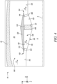
- Figure 3 is a schematic sectional side view of a thermal management system 100 for the gas turbine engine 10. Specifically, Figure 3 illustrates a schematic sectional side view of a portion of the gas turbine engine 10.
- a radial direction R is defined with respect to the principal rotational axis 9 of the gas turbine engine 10 in the bottom-to-top direction as shown in Figure 3 .
- terms that refer to a radial direction such as “radially outer”, “radially inner”, “radially extends”, “radially inwards”, “radially outwards”, “radially spaced apart”, “radial thickness”, and “radially proximal”, are with respect to the radial direction R.
- a circumferential direction C is defined with respect to the principal rotational axis 9 perpendicular to the page in the Figure 3 view.
- terms that refer to a circumferential direction such as “circumferentially extends”, “circumferentially extending”, “circumferentially surrounding”, “circumferentially inclined”, “circumferentially with respect to”, and “circumferentially disposed between”, are with respect to the circumferential direction C.
- An axial direction X is defined that is aligned with the principal rotational axis 9 of the gas turbine engine 10.
- terms that refer to an axial direction such as “axially disposed”, “axially extends”, “axially spaced apart”, and “axially proximal”, are with respect to the axial direction X.
- the thermal management system 100 includes a bypass inner wall 110 circumferentially surrounding the engine core 11 around the principal rotational axis 9 and extending along the principal rotational axis 9.
- the bypass inner wall 110 may include multiple section joined together to form a continuous wall surface.
- the bypass inner wall 110 is radially disposed between the engine core 11 and the nacelle 21 relative to the principal rotational axis 9, such that the main bypass duct 22 is defined between the bypass inner wall 110 and the nacelle 21.
- the main bypass duct 22 is delimited radially between the nacelle 21 and the bypass inner wall 110 of the thermal management system 100.
- the main bypass duct 22 may receive the bypass airflow B generated by the fan.
- the thermal management system 100 further includes an outer cowl 120 circumferentially surrounding and radially spaced apart from the bypass inner wall 110 relative to the principal rotational axis 9.
- the outer cowl 120 extends along the principal rotational axis 9 between an inlet end 122 and an outlet end 124.
- the outer cowl 120 is disposed within the main bypass duct 22.
- the outer cowl 120 and the bypass inner wall 110 define an outer cowl duct 126 therebetween.
- the outer cowl duct 126 may receive at least a portion of the bypass airflow B flowing through the main bypass duct 22. Specifically, at least a portion of the bypass airflow B may enter the outer cowl duct 126 from the inlet end 122 of the outer cowl 120 and exits the outer cowl duct 126 from the outlet end 124 of the outer cowl 120.
- outer cowl duct 126 may take a variety of forms, orientations, and geometries.
- the outer cowl duct 126 may include a variety of transitions, cross sectional areas, surface textures, and may be made of a variety of materials or combination of materials.
- the bypass inner wall 110 includes a first bypass surface 112 facing the outer cowl 120 and substantially parallel to the principal rotational axis 9.
- the bypass inner wall 110 further includes a second bypass surface 114 extending from the first bypass surface 112 and inclined obliquely relative to the principal rotational axis 9 away from the outer cowl 120.
- the bypass inner wall 110 further includes a third bypass surface 116 extending from and inclined obliquely to the second bypass surface 114.
- the third bypass surface 116 is further inclined obliquely relative to the principal rotational axis 9 towards the outer cowl 120.
- an inclination angle of the third bypass surface 116 relative to the principal rotational axis 9 is greater than an inclination angle of the second bypass surface 114 relative to the principal rotational axis 9.
- the bypass inner wall 110 further includes a fourth bypass surface 118 extending from the third bypass surface 116 and substantially parallel to the principal rotational axis 9. The first bypass surface 112 and the fourth bypass surface 118 may allow the bypass airflow B to enter and exit the outer cowl duct 126 substantially parallel to the principal rotational axis 9.
- the outer cowl 120 includes a first cowl surface 132 facing the bypass inner wall 110 and substantially parallel to the principal rotational axis 9. In some embodiments, the outer cowl 120 further includes a second cowl surface 134 facing the bypass inner wall 110 and substantially parallel to the principal rotational axis 9. In some embodiments, the second cowl surface 134 is axially and radially spaced apart from the first cowl surface 132 relative to the principal rotational axis 9. In some embodiments, the first and second cowl surfaces 132, 134 may allow the bypass airflow B to enter and exit the outer cowl duct 126 substantially parallel to the principal rotational axis 9.
- the outer cowl 120 further includes a third cowl surface 136 extending between the first cowl surface 132 and the second cowl surface 134.
- the third cowl surface 136 is inclined obliquely relative to the principal rotational axis 9 and substantially parallel to the third bypass surface 116 of the bypass inner wall 110.
- the thermal management system 100 further includes a plurality of inlet vanes 104 extending from the bypass inner wall 110 towards the outer cowl 120 and disposed proximal to the inlet end 122 of the outer cowl 120.
- the plurality of inlet vanes 104 are circumferentially spaced apart from each other relative to the principal rotational axis 9. In the illustrated embodiment of Figure 3 , only one inlet vane 104 from the plurality of inlet vanes 104 is visible.
- the thermal management system 100 further includes a plurality of outlet vanes 106 extending from the bypass inner wall 110 towards the outer cowl 120 and disposed proximal to the outlet end 124 of the outer cowl 120.
- the plurality of outlet vanes 106 are circumferentially spaced apart from each other relative to the principal rotational axis 9. In the illustrated embodiment of Figure 3 , only one outlet vane 106 from the plurality of outlet vanes 106 is visible.
- the thermal management system 100 further includes a heat exchanger 108 extending from the bypass inner wall 110 towards the outer cowl 120 and axially disposed between the inlet end 122 and the outlet end 124 relative to the principal rotational axis 9.
- the heat exchanger 108 extends between the third cowl surface 136 of the outer cowl 120 and the third bypass surface 116 of the bypass inner wall 110.
- the heat exchanger 108 may receive at least a portion of the bypass airflow B received within the outer cowl duct 126. In some embodiments, the heat exchanger 108 may be disposed in fluid communication with an engine cooling circuit or an accessory (e.g., a generator) cooling circuit. The heat exchanger 108 may exchange heat between flow streams. For example, the heat exchanger 108 may exchange heat between the bypass airflow B and an engine coolant utilized in the engine cooling circuit.
- the heat exchanger 108 may be made of a variety of materials and components. Further, the heat exchanger 108 may be any type of heat exchanger, such as, e.g., a matrix heat exchanger, a plate and fin type heat exchanger, etc. In the illustrated embodiment of Figure 3 , the heat exchanger 108 is inclined obliquely relative to the principal rotational axis 9. However, the heat exchanger 108 may also have other configurations based on a relative shape, orientation, and size of the outer cowl duct 126.
- the heat exchanger 108 may include a variety of forms, and may have a variety of configurations, orientation, shapes, lengths, etc. for exchanging heat. For example, the heat exchanger 108 may also be disposed perpendicular to the principal rotational axis 9 as shown in Figure 4 .
- the bypass inner wall 110 further includes a first bypass surface 113 facing the outer cowl 120 and substantially parallel to the principal rotational axis 9.
- the bypass inner wall 110 further includes a second bypass surface 115 extending from the first bypass surface 112 and inclined obliquely relative to the principal rotational axis 9 away from the outer cowl 120.
- the bypass inner wall 110 further includes a third bypass surface 117 extending from the second bypass surface 115 substantially parallel to the principal rotational axis 9.
- the bypass inner wall 110 further includes a fourth bypass surface 119 extending from the third bypass surface 117 and inclined obliquely relative to the principal rotational axis 9 towards the outer cowl 120.
- the bypass inner wall 110 further includes a fifth bypass surface 121 extending from the fourth bypass surface 119 and substantially parallel to the principal rotational axis 9.
- the first bypass surface 113 and the fifth bypass surface 121 may allow the bypass airflow B to enter and exit the outer cowl duct 126 substantially parallel to the principal rotational axis 9.
- the outer cowl 120 further includes a cowl surface 131 facing the bypass inner wall 110 and substantially parallel to the principal rotational axis 9.
- the heat exchanger 108 extends between the cowl surface 131 of the outer cowl 120 and the third bypass surface 117 of the bypass inner wall 110 substantially perpendicular to the principal rotational axis 9.
- the thermal management system 100 further includes the plurality of inlet vanes 104 extending from the bypass inner wall 110 towards the outer cowl 120 and disposed proximal to the inlet end 122 of the outer cowl 120.
- the thermal management system 100 further includes the plurality of outlet vanes 106 extending from the bypass inner wall 110 towards the outer cowl 120 and disposed proximal to the outlet end 124 of the outer cowl 120.
- the heat exchanger 108 may include a unitary body circumferentially extending around the principal rotational axis 9. In some embodiments, the heat exchanger 108 may only partially extend around the principal rotational axis 9. Any number of heat exchangers 108 may be used with the thermal management system 100. In a non-example, the gas turbine engine 10 may include multiple heat exchangers 108 disposed within the outer cowl duct 126.
- the thermal management system 100 further includes a plurality of first removable shims 144 corresponding to the plurality of inlet vanes 104.
- Each first removable shim 144 from the plurality of first removable shims 144 extends between and engages the outer cowl 120 and a corresponding inlet vane 104 from the plurality of inlet vanes 104.
- each of the plurality of first removable shims 144 engages the first cowl surface 132 of the outer cowl 120 and the corresponding inlet vane 104.
- only one first removable shim 144 from the plurality of first removable shims 144 is visible.
- Each of the plurality of first removable shims 144 is removable from between the corresponding inlet vane 104 and the outer cowl 120. In some embodiments, each of the plurality of first removable shims 144 is removable to vary a radial distance ID between the inlet end 122 of the outer cowl 120 and the bypass inner wall 110. In the illustrated embodiment of Figure 3 , each of the plurality of first removable shims 144 is disposed between the outer cowl 120 and the corresponding inlet vane 104, such that the inlet end 122 of the outer cowl 120 is radially spaced apart from the bypass inner wall 110 relative to the principal rotational axis 9 by a radial distance D1. In some embodiments, each of the plurality first removable shims 144 includes a thickness T1. In some embodiments, the thickness T1 may be a radial thickness of each of the plurality first removable shims 144.
- the thermal management system 100 further includes a plurality of second removable shims 146 corresponding to the plurality of outlet vanes 106.
- Each second removable shim 146 from the plurality of second removable shims 146 extends between and engages the outer cowl 120 and a corresponding outlet vane 106 from the plurality of outlet vanes 106.
- each of the plurality of second removable shims 146 engages the second cowl surface 134 of the outer cowl 120 and the corresponding outlet vane 106.
- only one second removable shim 146 from the plurality of second removable shims 146 is visible.
- Each of the plurality of second removable shims 146 is removable from between the corresponding outlet vane 106 and the outer cowl 120. In some embodiments, each of the plurality of second removable shims 146 is removable to vary a radial distance OD between the outlet end 124 of the outer cowl 120 and the bypass inner wall 110. In the illustrated embodiment of Figure 3 , each of the plurality of second removable shims 146 is disposed between the outer cowl 120 and the corresponding outlet vane 106, such that the outlet end 124 of the outer cowl 120 is radially spaced apart from the bypass inner wall 110 relative to the principal rotational axis 9 by a radial distance D2. In some embodiments, each of the plurality second removable shims 146 includes a thickness T2. In some embodiments, the thickness T2 may be a radial thickness of each of the plurality second removable shims 146.
- increase in the radial distances ID, OD may allow an increase in the bypass airflow B flowing through the outer cowl duct 126, thereby enhancing a heat rejection capacity of the heat exchanger 108.
- decrease in the radial distances ID, OD may allow a decrease in the bypass airflow B flowing through the outer cowl duct 126, thereby lowering the heat rejection capacity of the heat exchanger 108.
- the plurality of first removable shims 144 and the plurality of second removable shims 146 may allow the outer cowl 120 to be geometrically shifted in the axial direction X and/or the radial direction R relative to the principal rotational axis 9, thereby allowing variation in a performance of the heat exchanger 108 based on updated operational requirements of the gas turbine engine 10.
- the thermal management system 100 further includes a third removable shim 148 extending between and engaging the heat exchanger 108 and the outer cowl 120. Specifically, the third removable shim 148 engages the third cowl surface 136 of the outer cowl 120 and the heat exchanger 108. In some embodiments, the third removable shim 148 circumferentially extends around the principal rotational axis 9. In some embodiments, the third removable shim 148 is removable from between the heat exchanger 108 and the outer cowl 120. In some embodiments, the third removable shim 148 is removable such that the heat exchanger 108 remains engaged with the outer cowl 120 (or the third cowl surface 136 of the outer cowl 120). The third removable shim 148 has a thickness T3.
- the introduction of the plurality of first removable shims 144, the plurality of second removable shims 146, and the third removable shim 148 may not affect attachment mechanisms for the heat exchanger 108 and anchoring of a supporting structure for the outer cowl. 120.
- the plurality of first removable shims 144, the plurality of second removable shims 146, and the third removable shim 148 may become a part of the supporting structure for the outer cowl 120.
- the existing gas turbine engines 10 may not require significant modifications to accommodate the plurality of first removable shims 144, the plurality of second removable shims 146, and the third removable shim 148.
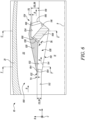
- FIG 5 is a schematic sectional side view of the thermal management system 100 where each of the plurality of first removable shims 144 (shown in Figure 3 ) is replaced by a corresponding first replacement shim 164, each of the plurality of second removable shims 146 (shown in Figure 3 ) is replaced by a corresponding second replacement shim 166, and the third removable shim 148 (shown in Figure 3 ) is replaced by a third replacement shim 168.
- the thermal management system 100 further includes the plurality of first replacement shims 164 corresponding to the plurality of first removable shims 144, the plurality of second replacement shims 166 corresponding to the plurality of second removable shims 146, and the third replacement shim 168 corresponding to the third removable shim 148.
- each of the plurality of first replacement shims 164 is removably disposed between and engages the outer cowl 120 and the corresponding inlet vane 104 after removal of the corresponding first removable shim 144.
- each of the plurality of second replacement shims 166 is removably disposed between and engages the outer cowl 120 and the corresponding outlet vane 106 after removal of the corresponding second removable shim 146.
- the third replacement shim 168 is removably disposed between and engages the heat exchanger 108 and the outer cowl 120 after removal of the third removable shim 148.
- each of the plurality of first removable shims 144, each of the plurality of second removable shims 146, and the third removable shim 148 may be manually replaced with a corresponding first replacement shim 164, a corresponding second replacement shim 166, and the third replacement shim 168, respectively, e.g., during maintenance of the gas turbine engine 10.
- each of the plurality of first replacement shims 164 includes a thickness T4 different from the thickness T1 (shown in Figure 3 ) of each of the plurality of first removable shims 144.
- the thickness T4 of each of the plurality of first replacement shims 164 is greater than the thickness T1 of each of the plurality of first removable shims 144 and the inlet end 122 of the outer cowl 120 is radially spaced apart from the bypass inner wall 110 relative to the principal rotational axis 9 by a radial distance D3 greater than the radial distance D1 (shown in Figure 3 ).
- each of the plurality of second replacement shims 166 includes a thickness T5 different from the thickness T2 (shown in Figure 3 ) of each of the plurality of second removable shims 146.
- the thickness T5 of each of the plurality of second replacement shims 166 is greater than the thickness T2 of each of the plurality of second removable shims 146 and the outlet end 124 of the outer cowl 120 is radially spaced apart from the bypass inner wall 110 relative to the principal rotational axis 9 by a radial distance D4 greater than the radial distance D2 (shown in Figure 3 ).
- the plurality of first replacement shims 164, the plurality of second replacement shims 166, and the third replacement shim 166 may geometrically shift or move the outer cowl 120 radially outwards relative to the principal rotational axis, thereby increasing a flow of air (i.e., the bypass airflow B) through the heat exchanger 108.
- This may allow a performance of the thermal management system 100 to be adjusted based on updated operational requirements of the gas turbine engine 10.
- a thickness T6 of the third replacement shim 168 is greater than the thickness T3 of the third removable shim 148 (shown in Figure 3 ).
- the third replacement shim 168 may be suitably chosen such that the heat exchanger 108 remains engaged with the outer cowl 120.
- FIG 6 is a schematic sectional side view of the thermal management system 100 where each of the plurality of first removable shims 144 (shown in Figures 3 ) is replaced by the corresponding first replacement shim 164, each of the plurality of second removable shims 146 (shown in Figure 3 ) is replaced by the corresponding second replacement shim 166, and the third removable shim 148 (shown in Figure 3 ) is replaced by the corresponding third replacement shim 168.
- the thickness T4 of each of the plurality of first replacement shims 164 is lesser than the thickness T1 of each of the plurality of first removable shims 144 (shown in Figure 3 )
- the thickness T5 of each of the plurality of second replacement shims 166 is lesser than the thickness T2 of each of the plurality of second removable shims 146 (shown in Figure 3 )
- the thickness T6 of the third replacement shim 168 is lesser than the thickness T3 of the third removable shim 148 (shown in Figure 3 ).
- the inlet end 122 of the outer cowl 120 is radially spaced apart from the bypass inner wall 110 relative to the principal rotational axis 9 by a radial distance D5 lesser than the radial distance D1 (shown in Figure 3 ). Further, the outlet end 124 of the outer cowl 120 is radially spaced apart from the bypass inner wall 110 relative to the principal rotational axis 9 by a radial distance D6 lesser than the radial distance D2 (shown in Figure 3 ).
- the plurality of first replacement shims 164, the plurality of second replacement shims 166, and the third replacement shim 168 may geometrically shift or move the outer cowl 120 radially inwards relative to the principal rotational axis 9, thereby reducing the flow of air (i.e., the bypass airflow B) through the heat exchanger 108. This may allow the performance of the thermal management system 100 to be adjusted based on updated operational requirements of the gas turbine engine 10.
- the plurality of first removable shims 144 (shown in Figure 3 ), the plurality of second removable shims 146 (see Fig. 3 ), and the third removable shim 148 (see Fig. 3 ) may be simultaneously replaceable or individually replaceable.
- the plurality of first replacement shims 164, the plurality of second replacement shims 166, and the third replacement shim 168 may be manufactured in groups of different thicknesses, thereby accommodating various settings of a performance of the heat exchanger 108.
- the plurality of first removable shims 144 (shown in Figure 3 ), the plurality of second removable shims 146 (shown in Figure 3 ), and the third removable shim 148 (shown in Figure 3 ) may provide a simple and a cost-effective solution for varying the performance of the thermal management system 100 after a design of the gas turbine engine 10 has been fixed. Further, maintenance requirements of the thermal management system 100 may be reduced due to the simple design of the shims, thereby reducing a downtime of the gas turbine engine 10.
- the thermal management system 100 may additionally include articulating joints, pivots, levers, etc., for adjusting the outer cowl 120.
- hydraulic / pneumatic systems may shift the outer cowl 120 or the whole thermal management system 100 including the outer cowl 120 and the heat exchanger 108.
- Alternative technologies may include use of shape memory alloys, etc.
- Figures 7A and 7B are enlarged schematic sectional side views of the inlet end 122 and the outlet end 124 of the outer cowl 120, respectively.
- Figure 7C is an enlarged schematic sectional side view of the thermal management system 100 including the outer cowl 120, the heat exchanger 108, and the third removable shim 148.
- the thermal management system 100 (shown in Figure 3 ) further includes a plurality of first countersunk bolts 154 corresponding to the plurality of first removable shims 144.
- each of the plurality of first countersunk bolts 154 extends through a corresponding first removable shim 144 from the plurality of first removable shims 144 and removably couples the corresponding first removable shim 144 to each of the outer cowl 120 and the corresponding inlet vane 104.
- each of the plurality of first countersunk bolts 154 may allow the corresponding first removable shim 144 to be held in position as well as removed from between the corresponding inlet vane 104 and the outer cowl 120 and replaced with the corresponding first replacement shim 164 (shown in Figures 5 and 6 ) based on updated operational requirements of the gas turbine engine 10.
- the plurality of first removable shims 144 may be positioned based a location feature (not shown) provided on the corresponding inlet vane 104 or the outer cowl 120 before removably coupling the corresponding first removable shim 144 to each of the outer cowl 120 and the corresponding inlet vane 104.
- the thermal management system 100 further includes a plurality of second countersunk bolts 156 corresponding to the plurality of second removable shims 146.
- each of the plurality of second countersunk bolts 156 extends through a corresponding second removable shim 146 from the plurality of second removable shims 146 and removably couples the corresponding second removable shim 146 to each of the outer cowl 120 and the corresponding outlet vane 106.
- each of the plurality of second countersunk bolts 156 may allow the corresponding second removable shim 146 to be held in position as well as removed from between the corresponding outlet vane 106 and the outer cowl 120 and replaced with the corresponding second replacement shim 166 (shown in Figures 5 and 6 ) based on updated operational requirements of the gas turbine engine 10.
- the plurality of second removable shims 146 may be positioned based a location feature (not shown) provided on the corresponding outlet vane 106 or the outer cowl 120 before removably coupling the corresponding second removable shim 146 to each of the outer cowl 120 and the corresponding outlet vane 106.
- the thermal management system 100 further includes one or more third countersunk bolts 160 corresponding to the third removable shim 148.
- the one or more third countersunk bolts 160 extends through the third removable shim 148 and removably couples the third removable shim 148 to the heat exchanger 108.
- only one third countersunk bolt 160 is shown for the purpose of illustration.
- the third countersunk bolt 160 may allow the third removable shim 148 to be held in position as well as removed from between the heat exchanger 108 and the outer cowl 120 and replaced with the third replacement shim 168 (shown in Figures 5 and 6 ).
- Figure 8 is a schematic sectional perspective view of a portion of the outer cowl 120 taken along a section line R-R' shown in Figure 5 .
- the outer cowl 120 further includes a plurality of panels 128 disposed circumferentially adjacent to each other relative to the principal rotational axis 9.
- a gap 158 exists between the plurality of panels 128 as each of the plurality of first removable shims 144 is replaced with the corresponding first replacement shim 164, each of the plurality of second removable shims 146 is replaced with the corresponding second replacement shim 166, and the third removable shim 148 is replaced with the third replacement shim 168.
- the gap 158 may appear between adjacent panels 128 due to radially outward movement of the plurality of panels 128 relative to the principal rotational axis 9 and the increase in the radial distances ID, OD between the inlet end 122 and the outlet end 124, respectively, of the outer cowl 120 and the bypass inner wall 110.
- the gap 158 may be reduced by filling the gap 158 with a filler 170.
- the gap 158 at the inlet end 122 of the outer cowl 120 may require to be closed due to foreign object damage tolerance requirements and aerodynamic considerations while the gap 158 at the outlet end 124 of the outer cowl 120 may be acceptable.
- the filler 170 may be made of any suitable material based on application requirements.
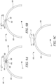
- Figure 9A is a schematic sectional view of the outer cowl 120 taken along sections lines P-P' or Q-Q' shown in Figure 3 .
- Figure 9B is a schematic sectional view of the outer cowl 120 taken along sections lines R-R' or S-S' shown in Figure 5 .
- Figure 9C is a schematic sectional view of the outer cowl 120 taken along sections lines T-T' or U-U' shown in Figure 6 .
- each panel 128 from the plurality of panels 128 defines a first circumferential edge 138 and a second circumferential edge 142 opposite to the first circumferential edge 138.
- the first circumferential edge 138 of one panel 128 from the plurality of panels 128 and the second circumferential edge 142 of an adjacent panel 128 from the plurality of panels 128 is visible.
- each panel 128 includes a recess 140 (shown in Figures 9A and 9B ) circumferentially extending partially from the second circumferential edge 142 towards the first circumferential edge 138 of the panel 128.
- the outer cowl 120 further includes a plurality of elastic lips 150 corresponding to the plurality of panels 128.
- each of the plurality of elastic lips 150 circumferentially extends from the first circumferential edge 138 of a corresponding panel 128 towards the second circumferential edge 142 of the adjacent panel 128 from the plurality of panels 128.
- each of the plurality of elastic lips 150 is slidably and at least partially received on the recess 140 of the adjacent panel 128.
- each of the plurality of elastic lips 150 may also axially extend along the principal rotational axis 9.
- the plurality of elastic lips 150 are coupled to the first circumferential edge 138 of the corresponding panel 128 via any suitable means, e.g., mechanical fasteners (e.g., screws, rivets, bolts, etc.), adhesives, etc.
- each of the plurality of elastic lips 150 may be flexibly coupled to the first circumferential edge 138 of the corresponding panel 128.
- the thermal management system 100 further includes a plurality of mechanical attachments 152 corresponding to the plurality of elastic lips 150.
- each of the plurality of mechanical attachments 152 couples a corresponding elastic lip 150 from the plurality of elastic lips 150 to the recess 140 of the adjacent panel 128.
- a single mechanical attachment 152 from the plurality of mechanical attachments 152 is schematically shown for the purpose of illustration.
- each of the plurality of mechanical attachments 152 may include a mechanical fastener (e.g., a bolt) movable within a slot (not shown) disposed on the recess 140 of the corresponding panel 128.
- each of the plurality of mechanical attachments 152 may allow the corresponding elastic lip 150 to move relative to the recess 140 of the adjacent panel 128 while being engaged with the recess 140 of the adjacent panel 128 at all times as the outer cowl 120 is positionally adjusted relative to the bypass inner wall 110 (shown in Figures 3-6 ).
- the plurality panels 128 are arranged such that the gap 158 exists between the first circumferential edge 138 of the panel 128 and the second circumferential edge 142 of the adjacent panel 128.
- the gap 158 (shown in Figure 8A) between the first circumferential edge 138 of the panel 128 and the second circumferential edge 142 of the adjacent panel 128 increases since the thickness T4 of each first replacement shim 166 is greater than the thickness T1 (shown in Figure 3 ) of each first removable shim 144, the
- the gap 158 (shown in Figure 9A ) between the first circumferential edge 138 of the panel 128 and the second circumferential edge 142 of the adjacent panel 128 increases due to radially outward movement of the plurality of panels 128 of the outer cowl 120 relative to the bypass inner wall 110.
- the plurality of elastic lips 150 may accommodate the increase in the gap 158 (shown in Figure 9A ) due to the radially outward movement of the plurality of panels 128.
- the plurality of elastic lips 150 may ensure a continuous smooth surface in the circumferential direction C (also shown in Figures 3-6 ), thereby allowing conformance at various circumferential locations of the outer cowl 120. Therefore, any mismatch between the plurality of panels 128 due to the movement of the outer cowl 120 may be mitigated. Further, the plurality of elastic lips 150 may minimize a fluid leakage from within the outer cowl 120 to the main bypass duct 22 to an acceptable level.
- each of the plurality of first removable shims 144 (shown in Figure 3 ) is replaced with the corresponding first replacement shim 164
- each of the plurality of second removable shims 146 (shown in Figure 3 ) is replaced with the corresponding second replacement shim 166
- the third removable shim 148 (shown in Figure 3 ) is replaced with the third replacement shim 166
- the gap 158 (shown in Figure 9A ) between the first circumferential edge 138 of the panel 128 and the second circumferential edge 142 of the adjacent panel 128 decreases since the thickness T4 of each first replacement shim 166 is lesser than the thickness T1 (shown in Figure 3 ) of each first removable shim 144, the thickness T5 of each second replacement shim 166 is lesser than the thickness T2 (shown in Figure 3 ) of each second removable shim 146, and the thickness T6 of the third replacement shim 168 is lesser than the thickness T3
- the gap 158 (shown in Figure 9A ) between the first circumferential edge 138 of the panel 128 and the second circumferential edge 142 of the adjacent panel 128 decreases due to radially inward movement of the plurality of panels 128 of the outer cowl 120 relative to the bypass inner wall 110.
- a curvature of the plurality panels 128 may be designed such that each of the plurality of recesses 140 may completely receive the elastic lip 150 of the adjacent panel 128 as each of the plurality of panels 128 move radially inwards relative to the principal rotational axis 9.
- the gap 158 (see Fig. 8A) between the first circumferential edge 138 of the panel 128 and the second circumferential edge 142 of the adjacent panel 128 may cease to exist.
- each of the plurality of elastic lips 150 may be thin enough and may include an appropriate elastic modulus such that each of the plurality of elastic lips 150 deflects when the plurality of panels 128 move radially inward or outward. Suitable materials (e.g., thermoplastic) may be chosen for the plurality of elastic lips 150 based on application requirements. In some embodiments, each of the plurality of elastic lips 150 may be manufactured by injecting different materials (with varying elastic properties) in a same mould. In some embodiments, each of the plurality of elastic lips 150 may include various layers of material with differing elastic properties.
- Figure 10 is a flow chart illustrating a method 200 for thermal management of the gas turbine engine 10 having the principal rotational axis 9, the engine core 11, and the nacelle 21.
- the method 200 will be described hereinafter with reference to the gas turbine engine 10 of Figures 1-6 and the thermal management system 100 of Figures 3-6 .
- the method 200 includes providing the bypass inner wall 110 circumferentially surrounding the engine core 11 around the principal rotational axis 9 and extending along the principal rotational axis 9.
- the bypass inner wall 110 is radially disposed between the engine core 11 and the nacelle 21 relative to the principal rotational axis 9, such that the main bypass duct 22 is defined between the bypass inner wall 110 and the nacelle 21.
- the method 200 further includes providing the outer cowl 120 circumferentially surrounding and radially spaced apart from the bypass inner wall 110 relative to the principal rotational axis 9.
- the outer cowl 120 extends along the principal rotational axis 9 between the inlet end 122 and the outlet end 124.
- the outer cowl 120 is disposed within the main bypass duct 22.
- the method 200 further includes providing the plurality of inlet vanes 104 extending from the bypass inner wall 110 towards the outer cowl 120 and disposed proximal to the inlet end 122 of the outer cowl 120.
- the plurality of inlet vanes 104 are circumferentially spaced apart from each other relative to the principal rotational axis 9.
- the method 200 further includes providing the plurality of outlet vanes 106 extending from the bypass inner wall 110 towards the outer cowl 120 and disposed proximal to the outlet end 124 of the outer cowl 120.
- the plurality of outlet vanes 106 are circumferentially spaced apart from each other relative to the principal rotational axis 9.
- the method 200 further includes providing the heat exchanger 108 extending from the bypass inner wall 110 towards the outer cowl 120 and axially disposed between the inlet end 122 and the outlet end 124 relative to the principal rotational axis.
- the method 200 further includes providing the plurality of first removable shims 144 corresponding to the plurality of inlet vanes 104. Each first removable shim 144 extends between and engages the outer cowl 120 and the corresponding inlet vane 104 from the plurality of inlet vanes 104.
- the method 200 further includes providing the plurality of second removable shims 146 corresponding to the plurality of outlet vanes 106. Each second removable shim 146 extends between and engages the outer cowl 120 and the corresponding outlet vane 106 from the plurality of outlet vanes 106.
- the method 200 further includes providing the third removable shim 148 extending between and engaging the heat exchanger 108 and the outer cowl 120. The third removable shim 148 circumferentially extends around the principal rotational axis 9.
- the method 200 further includes positionally adjusting the outer cowl 120 relative to the bypass inner wall 110 by: removing each of the plurality of first removable shims 144 from between the corresponding inlet vane 104 and the outer cowl 120; removing each of the plurality of second removable shims 146 from between the corresponding outlet vane 106 and the outer cowl 120; and removing the third removable shim 148 from between the heat exchanger 108 and the outer cowl 120.
- the method 200 further includes providing the plurality of second replacement shims 166 corresponding to the plurality of second removable shims 146.
- each of the plurality second replacement shims 166 includes the thickness T5 different from the thickness T2 of each of the plurality of second removable shims 146.
- the method 200 further includes removably disposing each of the plurality of second replacement shims 166 between the outer cowl 120 and the corresponding outlet vane 106 after removal of the corresponding second removable shim 146, such that each of the plurality of second replacement shims 166 engages each of the outer cowl 120 and the corresponding outlet vane 106.
- the method 200 further includes removably disposing the third replacement shim 168 between the heat exchanger 108 and the outer cowl 120 after removal of the third removable shim 148, such that the third replacement shim 168 engages each of the heat exchanger 108 and the outer cowl 120.
Landscapes
- Engineering & Computer Science (AREA)
- Chemical & Material Sciences (AREA)
- Combustion & Propulsion (AREA)
- Mechanical Engineering (AREA)
- General Engineering & Computer Science (AREA)
- Structures Of Non-Positive Displacement Pumps (AREA)
- Physics & Mathematics (AREA)
- Fluid Mechanics (AREA)
Abstract
Description
- The present disclosure generally relates to a thermal management system for a gas turbine engine and a method for thermal management of the gas turbine engine.
- Thermal management systems for gas turbine engines (and associated equipment) may manage heat generated and rejected by the gas turbine engine during operation to ensure that all engine fluids within the gas turbine engine are maintained at safe and effective temperatures at all times. Heat rejection requirements for the gas turbine engine may depend on operational conditions as well as design assumptions, which are characterised by uncertainties during operation of the gas turbine engine. Such uncertainties may vary throughout a design process of the gas turbine engine. Further, the operational conditions may change during a service life of the gas turbine engine, either due to environmental conditions, degradation, and /or deviation in an operational scope (e.g., use of sustainable aviation fuel). As a consequence, actual heat rejection may be different from a required demand, leading to incompatibility and/or operation of the gas turbine engine beyond its intended envelope, or even restricted operation.
- Prior solutions have historically introduced safety margins through design factors. These safety margins are derived based on a range of uncertainties which may not be explicitly quantified, resulting in pessimistically over-sized design factors. Such design factors may typically result in a system (i.e., a gas turbine engine design) that is over-designed to account for all combinations of known and unknown uncertainties. This approach may typically result in over-sizing and an increased weight of the system. This may be accompanied by a performance penalty across the gas turbine engine, including non-optimal specific fuel consumption (SFC), which must be accepted over a service life of the gas turbine engine. The oversized system may be required to operate at part-load which may further degrade an efficiency of the system. Adjustment in a system-level performance may be realised by alternative means, e.g., coolant-flow restrictors of a coolant-air heat exchanger system, which may further add to extra weight, complexity, and component count.
- In certain instances, the unknown uncertainties may still dominate, resulting in a system that is under-sized for a required duty cycle. A possible reason for this under-sizing may be an extension in an operational envelope of the gas turbine engine or the associated equipment (e.g., a gearbox, an auxiliary system, such as power electronics, etc.). Such requirements may appear later during an engine design process and/or in-service after the engine design process is complete.
- An approach to minimize the aforementioned consequences of requirement uncertainty may lead to introduction of active control systems which may manage the system within limits. However, the active control systems may in turn introduce additional failure scenarios and potential redundancy through duplication to ensure operational safety.
- According to a first aspect, there is provided a thermal management system for a gas turbine engine having a principal rotational axis, an engine core, and a nacelle. The thermal management system includes a bypass inner wall circumferentially surrounding the engine core around the principal rotational axis and extending along the principal rotational axis. The bypass inner wall is radially disposed between the engine core and the nacelle relative to the principal rotational axis, such that a main bypass duct is defined between the bypass inner wall and the nacelle. The thermal management system further includes an outer cowl circumferentially surrounding and radially spaced apart from the bypass inner wall relative to the principal rotational axis. The outer cowl extends along the principal rotational axis between an inlet end and an outlet end. The outer cowl is disposed within the main bypass duct. The thermal management system further includes a plurality of inlet vanes extending from the bypass inner wall towards the outer cowl and disposed proximal to the inlet end of the outer cowl. The plurality of inlet vanes are circumferentially spaced apart from each other relative to the principal rotational axis. The thermal management system further includes a plurality of outlet vanes extending from the bypass inner wall towards the outer cowl and disposed proximal to the outlet end of the outer cowl. The plurality of outlet vanes are circumferentially spaced apart from each other relative to the principal rotational axis. The thermal management system further includes a heat exchanger extending from the bypass inner wall towards the outer cowl and axially disposed between the inlet end and the outlet end relative to the principal rotational axis. The thermal management system further includes a plurality of first removable shims corresponding to the plurality of inlet vanes. Each first removable shim from the plurality of first removable shims extends between and engages the outer cowl and a corresponding inlet vane from the plurality of inlet vanes. The thermal management system further includes a plurality of second removable shims corresponding to the plurality of outlet vanes. Each second removable shim from the plurality of second removable shims extends between and engages the outer cowl and a corresponding outlet vane from the plurality of outlet vanes. The thermal management system further includes a third removable shim extending between and engaging the heat exchanger and the outer cowl. The third removable shim circumferentially extends around the principal rotational axis. For positionally adjusting the outer cowl relative to the bypass inner wall: each of the plurality of first removable shims is removable from between the corresponding inlet vane and the outer cowl; each of the plurality of second removable shims is removable from between the corresponding outlet vane and the outer cowl; and the third removable shim is removable from between the heat exchanger and the outer cowl.
- Use of the plurality of first removable shims, the plurality of second removable shims, and the third removable shim may allow the outer cowl to be positionally adjusted relative to the bypass inner wall. Thus, the plurality of first removable shims, the plurality of second removable shims, and the third removable shim may allow the outer cowl to be moved in an axial and/or a radial direction relative to the principal rotational axis, thereby increasing or decreasing geometric areas at the inlet end and the outlet end of the outer cowl. This may increase or decrease air flowing through the heat exchanger, thereby allowing a performance of the thermal management system to be adjusted based on updated operational requirements of the gas turbine engine after a design of the gas turbine engine has been fixed.
- The plurality of first removable shims and the plurality of second removable shims may be located at discrete circumferential positions around the principal rotational axis, thereby allowing the air flow through the heat exchanger without significant resistance to the flow of air. Further, the third removable shim may be removable such that the heat exchanger remains engaged with the outer cowl as the outer cowl is adjusted relative to the bypass inner wall. In some extreme circumstances, the third removable shim may be used to shroud a portion of the heat exchanger, thereby further varying the performance of the thermal management system. The plurality of first removable shims, the plurality of second removable shims, and the third removable shim may be manufactured in groups of different radial thicknesses, thereby accommodating various settings of a performance of the heat exchanger.
- Additionally, the introduction of the plurality of first removable shims, the plurality of second removable shims, and the third removable shim may not affect attachment mechanisms for the heat exchanger and anchoring of a supporting structure for the outer cowl. The plurality of first removable shims, the plurality of second removable shims, and the third removable shim may become a part of the supporting structure of the outer cowl. Thus, the existing gas turbine engines may not require significant modifications to accommodate the plurality of first removable shims, the plurality of second removable shims, and the third removable shim. Further, a relative movement of the inlet end and the outlet end may be used to alter interactions with adjacent components and hardware, if interactions appear dominant during development and/or in-service operation of the gas turbine engine after a basic design of the gas turbine engine is fixed.
- Thus, the plurality of first removable shims, the plurality of second removable shims, and the third removable shim may provide a simple and a cost-effective solution for varying the performance of the thermal management system. This may mitigate the need for an over-sized thermal management system for accommodating all combinations of known and unknown uncertainties since the performance of the thermal management system of the present disclosure may be adjusted based on the updated operational requirements of the gas turbine engine. This may further reduce a weight and a size of the gas turbine engine, thereby improving an overall efficiency of the gas turbine engine. Further, maintenance requirements of the thermal management system may be reduced due to a simple design of the plurality of first removable shims, the plurality of second removable shims, and the third removable shim, thereby reducing a downtime of the gas turbine engine.
- In the proposed solution, the performance of the thermal management system is not adjusted based on multiple components forming the outer cowl which would have otherwise resulted in excessive costs associated with multiple moulds / pressings. Instead, the proposed solution includes use of additional shims for adjusting the performance of the thermal management system as the shims may be designed and manufactured at reduced cost.
- In some embodiments, the bypass inner wall includes a first bypass surface facing the outer cowl and substantially parallel to the principal rotational axis. In some embodiments, the bypass inner wall further includes a second bypass surface extending from the first bypass surface and inclined obliquely relative to the principal rotational axis away from the outer cowl. In some embodiments, the bypass inner wall further includes a third bypass surface extending from and inclined obliquely to the second bypass surface. The third bypass surface is further inclined obliquely relative to the principal rotational axis towards the outer cowl. In some embodiments, the bypass inner wall further includes a fourth bypass surface extending from the third bypass surface and substantially parallel to the principal rotational axis.
- The first bypass surface and the fourth bypass surface may allow the air flow to enter and exit a duct defined between the outer cowl and the bypass inner wall substantially parallel to the principal rotational axis. In some cases, the heat exchanger may be inclined relative to the principal rotational axis. The second and third bypass surfaces may be inclined to accommodate the heat exchanger (which may be inclined) between the outer cowl and the bypass inner wall.
- In some embodiments, the outer cowl includes a first cowl surface facing the bypass inner wall and substantially parallel to the principal rotational axis. In some embodiments, the outer cowl further includes a second cowl surface facing the bypass inner wall and substantially parallel to the principal rotational axis. The second cowl surface is axially and radially spaced apart from the first cowl surface relative to the principal rotational axis. In some embodiments, the outer cowl further includes a third cowl surface extending between the first cowl surface and the second cowl surface. The third cowl surface is inclined obliquely relative to the principal rotational axis and substantially parallel to the third bypass surface of the bypass inner wall. The heat exchanger extends between the third cowl surface and the third bypass surface.
- The first cowl surface and the second cowl surface may allow the air flow to enter and exit the duct defined between the outer cowl and the bypass inner wall substantially parallel to the principal rotational axis. Further, the third cowl surface may be inclined obliquely relative to the principal rotational axis to accommodate the heat exchanger (in an inclined configuration) between the outer cowl and the bypass inner wall.
- In some embodiments, the outer cowl further includes a plurality of panels disposed circumferentially adjacent to each other relative to the principal rotational axis. Each panel from the plurality of panels defines a first circumferential edge and a second circumferential edge opposite to the first circumferential edge. Each panel includes a recess circumferentially extending partially from the second circumferential edge towards the first circumferential edge. In some embodiments, the outer cowl further includes a plurality of elastic lips corresponding to the plurality of panels. Each of the plurality of elastic lips circumferentially extends from the first circumferential edge of a corresponding panel towards the second circumferential edge of an adjacent panel from the plurality of panels. Each of the plurality of elastic lips is slidably and at least partially received on the recess of the adjacent panel.
- The plurality of elastic lips may deflect to accommodate any gaps generated between the plurality of panels due to radially inward or outward movement of the plurality of panels at the inlet end or the outlet end of the outer cowl. The plurality of elastic lips may be provided at circumferentially adjoining interfaces between the plurality of panels, i.e., between the first and second circumferential edges. The plurality of elastic lips may ensure a continuous and smooth surface in a circumferential direction, thereby allowing conformance at various circumferential locations of the outer cowl. Thus, any mismatch between the plurality of panels due to the movement of the outer cowl may be mitigated.
- In some embodiments, the thermal management system further includes a plurality of mechanical attachments corresponding to the plurality of elastic lips. Each of the plurality of mechanical attachments couples a corresponding elastic lip from the plurality of elastic lips to the recess of the adjacent panel. Each of the plurality of mechanical attachments (e.g., a bolt movable within a slot of the adjacent panel) may allow the corresponding elastic lip to move relative to the recess of the adjacent panel while being engaged with the recess of the adjacent panel at all times as the outer cowl is positionally adjusted relative to the bypass inner wall.
- In some embodiments, the thermal management system further includes a plurality of first countersunk bolts corresponding to the plurality of first removable shims. Each of the plurality of first countersunk bolts extends through a corresponding first removable shim from the plurality of first removable shims and removably couples the corresponding first removable shim to each of the outer cowl and the corresponding inlet vane. The plurality of first countersunk bolts may removably couple the corresponding first removable shim to each of the outer cowl and the corresponding inlet vane, thereby allowing the corresponding first removable shim to be replaced or removed as per updated operational requirements of the gas turbine engine.
- In some embodiments, the thermal management system further includes a plurality of second countersunk bolts corresponding to the plurality of second removable shims. Each of the second countersunk bolts extends through a corresponding second removable shim from the plurality of second removable shims and removably couples the corresponding second removable shim to each of the outer cowl and the corresponding outlet vane. The plurality of second countersunk bolts may removably couple the corresponding second removable shim to each of the outer cowl and the corresponding outlet vane, thereby allowing the corresponding second removable shim to be replaced or removed as per updated operational requirements of the gas turbine engine.
- In some embodiments, the thermal management system further includes a plurality of first replacement shims corresponding to the plurality of first removable shims. Each of the plurality of first replacement shims is removably disposed between and engages the outer cowl and the corresponding inlet vane after removal of the corresponding first removable shim. The plurality of first replacement shims may allow the outer cowl to be positionally adjusted relative to the bypass inner wall by replacing the plurality of first removable shims with the plurality of first replacement shims.
- In some embodiments, each of the plurality first replacement shims includes a thickness different from a thickness of each of the plurality of first removable shims. The radial distance between the inlet end of the outer cowl and the bypass inner wall may be increased or decreased by replacing the plurality of first removable shims with the plurality of first replacement shims, thereby altering the performance of the thermal management system based on updated operational requirements of the gas turbine engine.
- In some embodiments, the thermal management system further includes a plurality of second replacement shims corresponding to the plurality of second removable shims. Each of the plurality of second replacement shims is removably disposed between and engages the outer cowl and the corresponding outlet vane after removal of the corresponding second removable shim. The plurality of second replacement shims may allow the outer cowl to be positionally adjusted relative to the bypass inner wall by replacing the plurality of second removable shims with the plurality of second replacement shims.
- In some embodiments, each of the plurality second replacement shims includes a thickness different from a thickness of each of the plurality of second removable shims. The radial distance between the outlet end of the outer cowl and the bypass inner wall may be increased or decreased by replacing the plurality of second removable shims with the plurality of second replacement shims, thereby altering the performance of the thermal management system based on updated operational requirements of the gas turbine engine.
- In some embodiments, the thermal management system further includes a third replacement shim. This shim is removably disposed between and engages the heat exchanger and the outer cowl after removal of the third removable shim. The third replacement shim may replace the third removable shim such that the heat exchanger remains engaged with the outer cowl as the outer cowl is positionally adjusted relative to the bypass inner wall. A thickness of the third replacement shim may be different from a thickness of the third removable shim.
- According to a second aspect, there is provided a gas turbine engine. The gas turbine engine incudes a principal rotational axis and an engine core extending along the principal rotational axis. The gas turbine engine further incudes a nacelle circumferentially surrounding the engine core around the principal rotational axis. The gas turbine engine further incudes the thermal management system of the first aspect. The bypass inner wall of the thermal management system circumferentially surrounds the engine core around the principal rotational axis and extends along the principal rotational axis. The bypass inner wall is radially disposed between the engine core and the nacelle relative to the principal rotational axis, such that a main bypass duct is defined between the bypass inner wall and the nacelle.
- According to a third aspect, there is provided a method for thermal management of a gas turbine engine having a principal rotational axis, an engine core, and a nacelle. The method includes providing a bypass inner wall circumferentially surrounding the engine core around the principal rotational axis and extending along the principal rotational axis. The bypass inner wall is radially disposed between the engine core and the nacelle relative to the principal rotational axis, such that a main bypass duct is defined between the bypass inner wall and the nacelle. The method further includes providing an outer cowl circumferentially surrounding and radially spaced apart from the bypass inner wall relative to the principal rotational axis. The outer cowl extends along the principal rotational axis between an inlet end and an outlet end. The outer cowl is disposed within the main bypass duct. The method further includes providing a plurality of inlet vanes extending from the bypass inner wall towards the outer cowl and disposed proximal to the inlet end of the outer cowl. The plurality of inlet vanes are circumferentially spaced apart from each other relative to the principal rotational axis. The method further includes providing a plurality of outlet vanes extending from the bypass inner wall towards the outer cowl and disposed proximal to the outlet end of the outer cowl. The plurality of outlet vanes are circumferentially spaced apart from each other relative to the principal rotational axis. The method further includes providing a heat exchanger extending from the bypass inner wall towards the outer cowl and axially disposed between the inlet end and the outlet end relative to the principal rotational axis. The method further includes providing a plurality of first removable shims corresponding to the plurality of inlet vanes. Each first removable shim extends between and engages the outer cowl and a corresponding inlet vane from the plurality of inlet vanes. The method further includes providing a plurality of second removable shims corresponding to the plurality of outlet vanes. Each second removable shim extends between and engages the outer cowl and a corresponding outlet vane from the plurality of outlet vanes. The method further includes providing a third removable shim extending between and engaging the heat exchanger and the outer cowl. The third removable shim circumferentially extends around the principal rotational axis. The method further includes positionally adjusting the outer cowl relative to the bypass inner wall by: removing each of the plurality of first removable shims from between the corresponding inlet vane and the outer cowl; removing each of the plurality of second removable shims from between the corresponding outlet vane and the outer cowl; and removing the third removable shim from between the heat exchanger and the outer cowl.
- In some embodiments, the method further includes providing a plurality of first replacement shims corresponding to the plurality of first removable shims. Each of the plurality first replacement shims includes a thickness different from a thickness of each of the plurality of first removable shims. In some embodiments, the method further includes removably disposing each of the plurality of first replacement shims between the outer cowl and the corresponding inlet vane after removal of the corresponding first removable shim, such that each of the plurality of first replacement shims engages each of the outer cowl and the corresponding inlet vane.
- In some embodiments, the method further includes providing a plurality of second replacement shims corresponding to the plurality of second removable shims. Each of the plurality second replacement shims includes a thickness different from a thickness of each of the plurality of second removable shims. In some embodiments, the method further includes removably disposing each of the plurality of second replacement shims between the outer cowl and the corresponding outlet vane after removal of the corresponding second removable shim, such that each of the plurality of second replacement shims engages each of the outer cowl and the corresponding outlet vane.
- In some embodiments, the method further includes removably disposing a third replacement shim between the heat exchanger and the outer cowl after removal of the third removable shim, such that the third replacement shim engages each of the heat exchanger and the outer cowl. A thickness of the third replacement shim may be different from a thickness of the third removable shim.
- As noted elsewhere herein, the present disclosure may relate to a gas turbine engine. Such a gas turbine engine may comprise an engine core comprising a turbine, a combustor, a compressor, and a core shaft connecting the turbine to the compressor. Such a gas turbine engine may comprise a fan (having fan blades) located upstream of the engine core.
- Arrangements of the present disclosure may be particularly, although not exclusively, beneficial for fans that are driven via a gearbox. Accordingly, the gas turbine engine may comprise a gearbox that receives an input from the core shaft and outputs drive to the fan so as to drive the fan at a lower rotational speed than the core shaft. The input to the gearbox may be directly from the core shaft, or indirectly from the core shaft, for example via a spur shaft and/or gear. The core shaft may rigidly connect the turbine and the compressor, such that the turbine and compressor rotate at the same speed (with the fan rotating at a lower speed).
- The gas turbine engine as described and/or claimed herein may have any suitable general architecture. For example, the gas turbine engine may have any desired number of shafts that connect turbines and compressors, for example, one, two, or three shafts. Purely by way of example, the turbine connected to the core shaft may be a first turbine, the compressor connected to the core shaft may be a first compressor, and the core shaft may be a first core shaft. The engine core may further comprise a second turbine, a second compressor, and a second core shaft connecting the second turbine to the second compressor. The second turbine, second compressor, and second core shaft may be arranged to rotate at a higher rotational speed than the first core shaft.
- In such an arrangement, the second compressor may be positioned axially downstream of the first compressor. The second compressor may be arranged to receive (for example directly receive, for example via a generally annular duct) flow from the first compressor.
- In any gas turbine engine as described and/or claimed herein, a combustor may be provided axially downstream of the fan and compressor(s). For example, the combustor may be directly downstream of (for example at the exit of) the second compressor, where a second compressor is provided. By way of further example, the flow at the exit to the combustor may be provided to the inlet of the second turbine, where a second turbine is provided. The combustor may be provided upstream of the turbine(s).
- The or each compressor (for example the first compressor and second compressor as described above) may comprise any number of stages, for example multiple stages. Each stage may comprise a row of rotor blades and a row of stator vanes, which may be variable stator vanes (in that their angle of incidence may be variable). The row of rotor blades and the row of stator vanes may be axially offset from each other.
- The or each turbine (for example the first turbine and second turbine as described above) may comprise any number of stages, for example multiple stages. Each stage may comprise a row of rotor blades and a row of stator vanes. The row of rotor blades and the row of stator vanes may be axially offset from each other.
- Gas turbine engines in accordance with the present disclosure may have any desired bypass ratio, where the bypass ratio is defined as the ratio of the mass flow rate of the flow through the main bypass duct to the mass flow rate of the flow through the core at cruise conditions. In some arrangements the bypass ratio may be greater than (or on the order of) any of the following: 10, 10.5, 11, 11.5, 12, 12.5, 13, 13.5, 14, 14.5, 15, 15.5, 16, 16.5, 17, 17.5, 18, 18.5, 19, 19.5 or20. The bypass ratio may be in an inclusive range bounded by any two of the values in the previous sentence (i.e. the values may form upper or lower bounds), for example in the range of from 12 to 16, 13 to 15, or 13 to 14. The main bypass duct may be substantially annular. The main bypass duct may be radially outside the engine core. The radially outer surface of the main bypass duct may be defined by a nacelle and/or a fan case.
- Specific thrust of an engine may be defined as the net thrust of the engine divided by the total mass flow through the engine. At cruise conditions, the specific thrust of an engine described and/or claimed herein may be less than (or on the order of) any of the following: 110 Nkg-1s, 105 Nkg-1s, 100 Nkg-1s, 95 Nkg-1s, 90 Nkg-1s, 85 Nkg-1s or 80 Nkg-'s. The specific thrust may be in an inclusive range bounded by any two of the values in the previous sentence (i.e., the values may form upper or lower bounds), for example in the range of from 80 Nkg-'s to 100 Nkg-1s, or 85 Nkg-1s to 95 Nkg-'s. Such engines may be particularly efficient in comparison with conventional gas turbine engines.
- A fan blade and/or aerofoil portion of a fan blade described and/or claimed herein may be manufactured from any suitable material or combination of materials. For example, at least a part of the fan blade and/or aerofoil may be manufactured at least in part from a composite, for example a metal matrix composite and/or an organic matrix composite, such as carbon fibre.
- The fan of a gas turbine as described and/or claimed herein may have any desired number of fan blades, for example 14, 16, 18, 20, 22, 24 or 26 fan blades.
- The skilled person will appreciate that except where mutually exclusive, a feature or parameter described in relation to any one of the above aspects may be applied to any other aspect. Furthermore, except where mutually exclusive, any feature or parameter described herein may be applied to any aspect and/or combined with any other feature or parameter described herein.
- Embodiments will now be described by way of example only, with reference to the Figures:
-
Figure 1 is a sectional side view of a gas turbine engine; -
Figure 2 is a close-up sectional side view of an upstream portion of a gas turbine engine; -
Figure 3 is a schematic sectional side view of a thermal management system for the gas turbine engine; -
Figure 4 is a schematic sectional side view of the thermal management system; -
Figure 5 is a schematic sectional side view of the thermal management system where each of a plurality of first removable shims is replaced by a corresponding first replacement shim, each of a plurality of second removable shims is replaced by a corresponding second replacement shim, and a third removable shim is replaced by a third replacement shim; -
Figure 6 is a schematic sectional side view of the thermal management system where each of the plurality of first removable shims is replaced by the corresponding first replacement shim, each of the plurality of second removable shims is replaced by the corresponding second replacement shim, and the third removable shim is replaced by the third replacement shim; -
Figures 7A and 7B are enlarged schematic sectional side views of an inlet end and an outlet end of an outer cowl, respectively; -
Figure 7C is an enlarged schematic sectional side view of the thermal management system including the outer cowl, the third removable shim, and a heat exchanger; -
Figure 8 is a schematic sectional perspective view of a portion of the outer cowl taken along a section line R-R' shown inFigure 5 ; -
Figure 9A is a schematic sectional view of the outer cowl taken along a section line P-P' or a section line Q-Q' shown inFigure 3 ; -
Figure 9B is a schematic sectional view of the outer cowl taken along a section line R-R' or a section line S-S' shown inFigure 5 ; -
Figure 9C is a schematic sectional view of the outer cowl taken along a section line T-T' or a section line U-U' shown inFigure 6 ; and -
Figure 10 is a flow chart illustrating a method for thermal management of the gas turbine engine. - Aspects and embodiments of the present disclosure will now be discussed with reference to the drawings. Further aspects and embodiments will be apparent to those skilled in the art.
-
Figure 1 illustrates agas turbine engine 10 having a principalrotational axis 9. Thegas turbine engine 10 comprises anair intake 12 and apropulsive fan 23 that generates two airflows: a core airflow A and a bypass airflow B. Thegas turbine engine 10 comprises anengine core 11 extending along the principalrotational axis 9 and receiving the core airflow A. Theengine core 11 comprises, in axial flow series, alow pressure compressor 14, ahigh pressure compressor 15,combustion equipment 16, ahigh pressure turbine 17, alow pressure turbine 19, and acore exhaust nozzle 20. Thegas turbine engine 10 further comprises anacelle 21 circumferentially surrounding theengine core 11 around the principalrotational axis 9 and defining amain bypass duct 22 and abypass exhaust nozzle 18. The bypass airflow B flows through themain bypass duct 22. Thefan 23 is attached to and driven by thelow pressure turbine 19 via ashaft 26 and anepicyclic gearbox 30. - In use, the core airflow A is accelerated and compressed by the
low pressure compressor 14 and directed into thehigh pressure compressor 15 where further compression takes place. The compressed air exhausted from thehigh pressure compressor 15 is directed into thecombustion equipment 16 where it is mixed with fuel and the mixture is combusted. The resultant hot combustion products then expand through, and thereby drive, the high pressure andlow pressure turbines core exhaust nozzle 20 to provide some propulsive thrust. Thehigh pressure turbine 17 drives thehigh pressure compressor 15 by a suitable interconnectingshaft 27. Thefan 23 generally provides the majority of the propulsive thrust. Theepicyclic gearbox 30 is a reduction gearbox. - The
gas turbine engine 10 further includes athermal management system 100. Thethermal management system 100 may manage heat generated and rejected by thegas turbine engine 10 during operation to ensure that all engine fluids (or fluids from associated equipment) within thegas turbine engine 10 are maintained at safe and effective temperatures at all times. In some embodiments, thethermal management system 100 may be disposed in fluid communication with themain bypass duct 22 and may receive at least a portion of the bypass airflow B from themain bypass duct 22. For example, the bypass airflow B may be utilized in thethermal management system 100 for cooling the engine fluids. - An exemplary arrangement for a geared fan
gas turbine engine 10 is shown inFigure 2 . The low pressure turbine 19 (seeFigure 1 ) drives theshaft 26, which is coupled to a sun wheel, or asun gear 28 of theepicyclic gearbox 30. Radially outwardly of thesun gear 28 and intermeshing therewith is a plurality of planet gears 32 that are coupled together by aplanet carrier 34. Theplanet carrier 34 constrains the planet gears 32 to process around thesun gear 28 in synchronicity whilst enabling eachplanet gear 32 to rotate about its own axis. Theplanet carrier 34 is coupled vialinkages 36 to thefan 23 in order to drive its rotation about the principalrotational axis 9. Radially outwardly of the planet gears 32 and intermeshing therewith is an annulus orring gear 38 that is coupled, vialinkages 40, to a stationary supportingstructure 24. - Note that the terms "low pressure turbine" and "low pressure compressor" as used herein may be taken to mean the lowest pressure turbine stages and lowest pressure compressor stages (i.e., not including the fan 23), respectively, and/or the turbine and compressor stages that are connected together by the
shaft 26 with the lowest rotational speed in the engine (i.e., not including the gearbox output shaft that drives the fan 23). In some literature, the "low pressure turbine" and "low pressure compressor" referred to herein may alternatively be known as the "intermediate pressure turbine" and "intermediate pressure compressor". Where such alternative nomenclature is used, thefan 23 may be a first, or lowest pressure, compression stage. - Accordingly, the present disclosure extends to a gas turbine engine having any arrangement of gearbox styles (for example, star or planetary), support structures, input and output shaft arrangement, and bearing locations. Optionally, the
epicyclic gearbox 30 may drive additional and/or alternative components (e.g., the intermediate pressure compressor and/or a booster compressor). - Other gas turbine engines to which the present disclosure may be applied may have alternative configurations. For example, such engines may have an alternative number of compressors and/or turbines and/or an alternative number of interconnecting shafts. By way of further example, the
gas turbine engine 10 shown inFigure 1 has asplit flow nozzle main bypass duct 22 has its ownbypass exhaust nozzle 18 that is separate to and radially outside thecore exhaust nozzle 20. However, this is not limiting, and any aspect of the present disclosure may also apply to engines in which the flow through themain bypass duct 22 and the flow through theengine core 11 are mixed, or combined, before (or upstream of) a single nozzle, which may be referred to as a mixed flow nozzle. One or both nozzles (whether mixed or split flow) may have a fixed or variable area. Whilst the described example relates to a turbofan engine, the disclosure may apply, for example, to any type of gas turbine engine, such as an open rotor (in which the fan stage is not surrounded by a nacelle), or turboprop engine, for example. In some arrangements, thegas turbine engine 10 may not comprise theepicyclic gearbox 30. - The geometry of the
gas turbine engine 10, and components thereof, is defined by a conventional axis system, comprising an axial direction (which is aligned with the principal rotational axis 9), a radial direction (in the bottom-to-top direction inFigure 1 ), and a circumferential direction (perpendicular to the page in theFigure 1 view). The axial, radial and circumferential directions are mutually perpendicular. -
Figure 3 is a schematic sectional side view of athermal management system 100 for thegas turbine engine 10. Specifically,Figure 3 illustrates a schematic sectional side view of a portion of thegas turbine engine 10. A radial direction R is defined with respect to the principalrotational axis 9 of thegas turbine engine 10 in the bottom-to-top direction as shown inFigure 3 . As used herein, terms that refer to a radial direction, such as "radially outer", "radially inner", "radially extends", "radially inwards", "radially outwards", "radially spaced apart", "radial thickness", and "radially proximal", are with respect to the radial direction R. A circumferential direction C is defined with respect to the principalrotational axis 9 perpendicular to the page in theFigure 3 view. As used herein, terms that refer to a circumferential direction, such as "circumferentially extends", "circumferentially extending", "circumferentially surrounding", "circumferentially inclined", "circumferentially with respect to", and "circumferentially disposed between", are with respect to the circumferential direction C. An axial direction X is defined that is aligned with the principalrotational axis 9 of thegas turbine engine 10. As used herein, terms that refer to an axial direction, such as "axially disposed", "axially extends", "axially spaced apart", and "axially proximal", are with respect to the axial direction X. - Referring to
Figures 1 and3 , thethermal management system 100 includes a bypassinner wall 110 circumferentially surrounding theengine core 11 around the principalrotational axis 9 and extending along the principalrotational axis 9. In some embodiments, the bypassinner wall 110 may include multiple section joined together to form a continuous wall surface. The bypassinner wall 110 is radially disposed between theengine core 11 and thenacelle 21 relative to the principalrotational axis 9, such that themain bypass duct 22 is defined between the bypassinner wall 110 and thenacelle 21. Thus, themain bypass duct 22 is delimited radially between thenacelle 21 and the bypassinner wall 110 of thethermal management system 100. In some embodiments, themain bypass duct 22 may receive the bypass airflow B generated by the fan. - The
thermal management system 100 further includes anouter cowl 120 circumferentially surrounding and radially spaced apart from the bypassinner wall 110 relative to the principalrotational axis 9. Theouter cowl 120 extends along the principalrotational axis 9 between aninlet end 122 and anoutlet end 124. Theouter cowl 120 is disposed within themain bypass duct 22. In some embodiments, theouter cowl 120 and the bypassinner wall 110 define anouter cowl duct 126 therebetween. In some embodiment, theouter cowl duct 126 may receive at least a portion of the bypass airflow B flowing through themain bypass duct 22. Specifically, at least a portion of the bypass airflow B may enter theouter cowl duct 126 from theinlet end 122 of theouter cowl 120 and exits theouter cowl duct 126 from theoutlet end 124 of theouter cowl 120. - It should be understood that the
outer cowl duct 126 may take a variety of forms, orientations, and geometries. Theouter cowl duct 126 may include a variety of transitions, cross sectional areas, surface textures, and may be made of a variety of materials or combination of materials. - As shown in
Figure 3 , in some embodiments, the bypassinner wall 110 includes afirst bypass surface 112 facing theouter cowl 120 and substantially parallel to the principalrotational axis 9. In some embodiments, the bypassinner wall 110 further includes asecond bypass surface 114 extending from thefirst bypass surface 112 and inclined obliquely relative to the principalrotational axis 9 away from theouter cowl 120. In some embodiments, the bypassinner wall 110 further includes athird bypass surface 116 extending from and inclined obliquely to thesecond bypass surface 114. In some embodiments, thethird bypass surface 116 is further inclined obliquely relative to the principalrotational axis 9 towards theouter cowl 120. - In the illustrated embodiment of
Figure 3 , an inclination angle of thethird bypass surface 116 relative to the principalrotational axis 9 is greater than an inclination angle of thesecond bypass surface 114 relative to the principalrotational axis 9. In some embodiments, the bypassinner wall 110 further includes afourth bypass surface 118 extending from thethird bypass surface 116 and substantially parallel to the principalrotational axis 9. Thefirst bypass surface 112 and thefourth bypass surface 118 may allow the bypass airflow B to enter and exit theouter cowl duct 126 substantially parallel to the principalrotational axis 9. - In some embodiments, the
outer cowl 120 includes afirst cowl surface 132 facing the bypassinner wall 110 and substantially parallel to the principalrotational axis 9. In some embodiments, theouter cowl 120 further includes asecond cowl surface 134 facing the bypassinner wall 110 and substantially parallel to the principalrotational axis 9. In some embodiments, thesecond cowl surface 134 is axially and radially spaced apart from thefirst cowl surface 132 relative to the principalrotational axis 9. In some embodiments, the first and second cowl surfaces 132, 134 may allow the bypass airflow B to enter and exit theouter cowl duct 126 substantially parallel to the principalrotational axis 9. In some embodiments, theouter cowl 120 further includes athird cowl surface 136 extending between thefirst cowl surface 132 and thesecond cowl surface 134. In some embodiments, thethird cowl surface 136 is inclined obliquely relative to the principalrotational axis 9 and substantially parallel to thethird bypass surface 116 of the bypassinner wall 110. - The
thermal management system 100 further includes a plurality ofinlet vanes 104 extending from the bypassinner wall 110 towards theouter cowl 120 and disposed proximal to theinlet end 122 of theouter cowl 120. The plurality ofinlet vanes 104 are circumferentially spaced apart from each other relative to the principalrotational axis 9. In the illustrated embodiment ofFigure 3 , only oneinlet vane 104 from the plurality ofinlet vanes 104 is visible. - The
thermal management system 100 further includes a plurality ofoutlet vanes 106 extending from the bypassinner wall 110 towards theouter cowl 120 and disposed proximal to theoutlet end 124 of theouter cowl 120. The plurality ofoutlet vanes 106 are circumferentially spaced apart from each other relative to the principalrotational axis 9. In the illustrated embodiment ofFigure 3 , only oneoutlet vane 106 from the plurality ofoutlet vanes 106 is visible. - The
thermal management system 100 further includes aheat exchanger 108 extending from the bypassinner wall 110 towards theouter cowl 120 and axially disposed between theinlet end 122 and theoutlet end 124 relative to the principalrotational axis 9. In some embodiments, theheat exchanger 108 extends between thethird cowl surface 136 of theouter cowl 120 and thethird bypass surface 116 of the bypassinner wall 110. - In some embodiments, the
heat exchanger 108 may receive at least a portion of the bypass airflow B received within theouter cowl duct 126. In some embodiments, theheat exchanger 108 may be disposed in fluid communication with an engine cooling circuit or an accessory (e.g., a generator) cooling circuit. Theheat exchanger 108 may exchange heat between flow streams. For example, theheat exchanger 108 may exchange heat between the bypass airflow B and an engine coolant utilized in the engine cooling circuit. - The
heat exchanger 108 may be made of a variety of materials and components. Further, theheat exchanger 108 may be any type of heat exchanger, such as, e.g., a matrix heat exchanger, a plate and fin type heat exchanger, etc. In the illustrated embodiment ofFigure 3 , theheat exchanger 108 is inclined obliquely relative to the principalrotational axis 9. However, theheat exchanger 108 may also have other configurations based on a relative shape, orientation, and size of theouter cowl duct 126. Theheat exchanger 108 may include a variety of forms, and may have a variety of configurations, orientation, shapes, lengths, etc. for exchanging heat. For example, theheat exchanger 108 may also be disposed perpendicular to the principalrotational axis 9 as shown inFigure 4 . - Referring to
Figure 4 , the bypassinner wall 110 further includes afirst bypass surface 113 facing theouter cowl 120 and substantially parallel to the principalrotational axis 9. In some embodiments, the bypassinner wall 110 further includes asecond bypass surface 115 extending from thefirst bypass surface 112 and inclined obliquely relative to the principalrotational axis 9 away from theouter cowl 120. In some embodiments, the bypassinner wall 110 further includes athird bypass surface 117 extending from thesecond bypass surface 115 substantially parallel to the principalrotational axis 9. In some embodiments, the bypassinner wall 110 further includes afourth bypass surface 119 extending from thethird bypass surface 117 and inclined obliquely relative to the principalrotational axis 9 towards theouter cowl 120. In some embodiments, the bypassinner wall 110 further includes afifth bypass surface 121 extending from thefourth bypass surface 119 and substantially parallel to the principalrotational axis 9. - The
first bypass surface 113 and thefifth bypass surface 121 may allow the bypass airflow B to enter and exit theouter cowl duct 126 substantially parallel to the principalrotational axis 9. - In some embodiments, the
outer cowl 120 further includes acowl surface 131 facing the bypassinner wall 110 and substantially parallel to the principalrotational axis 9. In some embodiments, theheat exchanger 108 extends between thecowl surface 131 of theouter cowl 120 and thethird bypass surface 117 of the bypassinner wall 110 substantially perpendicular to the principalrotational axis 9. Thethermal management system 100 further includes the plurality ofinlet vanes 104 extending from the bypassinner wall 110 towards theouter cowl 120 and disposed proximal to theinlet end 122 of theouter cowl 120. Thethermal management system 100 further includes the plurality ofoutlet vanes 106 extending from the bypassinner wall 110 towards theouter cowl 120 and disposed proximal to theoutlet end 124 of theouter cowl 120. - In some embodiments, the
heat exchanger 108 may include a unitary body circumferentially extending around the principalrotational axis 9. In some embodiments, theheat exchanger 108 may only partially extend around the principalrotational axis 9. Any number ofheat exchangers 108 may be used with thethermal management system 100. In a non-example, thegas turbine engine 10 may includemultiple heat exchangers 108 disposed within theouter cowl duct 126. - Referring again to
Figure 3 , thethermal management system 100 further includes a plurality of firstremovable shims 144 corresponding to the plurality ofinlet vanes 104. Each firstremovable shim 144 from the plurality of firstremovable shims 144 extends between and engages theouter cowl 120 and acorresponding inlet vane 104 from the plurality ofinlet vanes 104. Specifically, each of the plurality of firstremovable shims 144 engages thefirst cowl surface 132 of theouter cowl 120 and thecorresponding inlet vane 104. In the illustrated embodiment ofFigure 3 , only one firstremovable shim 144 from the plurality of firstremovable shims 144 is visible. - Each of the plurality of first
removable shims 144 is removable from between thecorresponding inlet vane 104 and theouter cowl 120. In some embodiments, each of the plurality of firstremovable shims 144 is removable to vary a radial distance ID between theinlet end 122 of theouter cowl 120 and the bypassinner wall 110. In the illustrated embodiment ofFigure 3 , each of the plurality of firstremovable shims 144 is disposed between theouter cowl 120 and thecorresponding inlet vane 104, such that theinlet end 122 of theouter cowl 120 is radially spaced apart from the bypassinner wall 110 relative to the principalrotational axis 9 by a radial distance D1. In some embodiments, each of the plurality firstremovable shims 144 includes a thickness T1. In some embodiments, the thickness T1 may be a radial thickness of each of the plurality firstremovable shims 144. - The
thermal management system 100 further includes a plurality of secondremovable shims 146 corresponding to the plurality of outlet vanes 106. Each secondremovable shim 146 from the plurality of secondremovable shims 146 extends between and engages theouter cowl 120 and acorresponding outlet vane 106 from the plurality of outlet vanes 106. Specifically, each of the plurality of secondremovable shims 146 engages thesecond cowl surface 134 of theouter cowl 120 and thecorresponding outlet vane 106. In the illustrated embodiment ofFigure 3 , only one secondremovable shim 146 from the plurality of secondremovable shims 146 is visible. - Each of the plurality of second
removable shims 146 is removable from between thecorresponding outlet vane 106 and theouter cowl 120. In some embodiments, each of the plurality of secondremovable shims 146 is removable to vary a radial distance OD between theoutlet end 124 of theouter cowl 120 and the bypassinner wall 110. In the illustrated embodiment ofFigure 3 , each of the plurality of secondremovable shims 146 is disposed between theouter cowl 120 and thecorresponding outlet vane 106, such that theoutlet end 124 of theouter cowl 120 is radially spaced apart from the bypassinner wall 110 relative to the principalrotational axis 9 by a radial distance D2. In some embodiments, each of the plurality secondremovable shims 146 includes a thickness T2. In some embodiments, the thickness T2 may be a radial thickness of each of the plurality secondremovable shims 146. - In some embodiments, increase in the radial distances ID, OD may allow an increase in the bypass airflow B flowing through the
outer cowl duct 126, thereby enhancing a heat rejection capacity of theheat exchanger 108. Alternatively, decrease in the radial distances ID, OD may allow a decrease in the bypass airflow B flowing through theouter cowl duct 126, thereby lowering the heat rejection capacity of theheat exchanger 108. Thus, the plurality of firstremovable shims 144 and the plurality of secondremovable shims 146 may allow theouter cowl 120 to be geometrically shifted in the axial direction X and/or the radial direction R relative to the principalrotational axis 9, thereby allowing variation in a performance of theheat exchanger 108 based on updated operational requirements of thegas turbine engine 10. - The
thermal management system 100 further includes a thirdremovable shim 148 extending between and engaging theheat exchanger 108 and theouter cowl 120. Specifically, the thirdremovable shim 148 engages thethird cowl surface 136 of theouter cowl 120 and theheat exchanger 108. In some embodiments, the thirdremovable shim 148 circumferentially extends around the principalrotational axis 9. In some embodiments, the thirdremovable shim 148 is removable from between theheat exchanger 108 and theouter cowl 120. In some embodiments, the thirdremovable shim 148 is removable such that theheat exchanger 108 remains engaged with the outer cowl 120 (or thethird cowl surface 136 of the outer cowl 120). The thirdremovable shim 148 has a thickness T3. - The introduction of the plurality of first
removable shims 144, the plurality of secondremovable shims 146, and the thirdremovable shim 148 may not affect attachment mechanisms for theheat exchanger 108 and anchoring of a supporting structure for the outer cowl. 120. The plurality of firstremovable shims 144, the plurality of secondremovable shims 146, and the thirdremovable shim 148 may become a part of the supporting structure for theouter cowl 120. Thus, the existinggas turbine engines 10 may not require significant modifications to accommodate the plurality of firstremovable shims 144, the plurality of secondremovable shims 146, and the thirdremovable shim 148. -
Figure 5 is a schematic sectional side view of thethermal management system 100 where each of the plurality of first removable shims 144 (shown inFigure 3 ) is replaced by a correspondingfirst replacement shim 164, each of the plurality of second removable shims 146 (shown inFigure 3 ) is replaced by a correspondingsecond replacement shim 166, and the third removable shim 148 (shown inFigure 3 ) is replaced by athird replacement shim 168. In some embodiments, thethermal management system 100 further includes the plurality of first replacement shims 164 corresponding to the plurality of firstremovable shims 144, the plurality of second replacement shims 166 corresponding to the plurality of secondremovable shims 146, and thethird replacement shim 168 corresponding to the thirdremovable shim 148. - In the illustrated embodiment of
Figure 5 , each of the plurality of first replacement shims 164 is removably disposed between and engages theouter cowl 120 and thecorresponding inlet vane 104 after removal of the corresponding firstremovable shim 144. In some embodiments, each of the plurality of second replacement shims 166 is removably disposed between and engages theouter cowl 120 and thecorresponding outlet vane 106 after removal of the corresponding secondremovable shim 146. In some embodiments, thethird replacement shim 168 is removably disposed between and engages theheat exchanger 108 and theouter cowl 120 after removal of the thirdremovable shim 148. In some embodiments, each of the plurality of firstremovable shims 144, each of the plurality of secondremovable shims 146, and the thirdremovable shim 148 may be manually replaced with a correspondingfirst replacement shim 164, a correspondingsecond replacement shim 166, and thethird replacement shim 168, respectively, e.g., during maintenance of thegas turbine engine 10. - In some embodiments, each of the plurality of first replacement shims 164 includes a thickness T4 different from the thickness T1 (shown in
Figure 3 ) of each of the plurality of firstremovable shims 144. In the illustrated embodiment ofFigure 5 , the thickness T4 of each of the plurality of first replacement shims 164 is greater than the thickness T1 of each of the plurality of firstremovable shims 144 and theinlet end 122 of theouter cowl 120 is radially spaced apart from the bypassinner wall 110 relative to the principalrotational axis 9 by a radial distance D3 greater than the radial distance D1 (shown inFigure 3 ). - In some embodiments, each of the plurality of second replacement shims 166 includes a thickness T5 different from the thickness T2 (shown in
Figure 3 ) of each of the plurality of secondremovable shims 146. In the illustrated embodiment ofFigure 5 , the thickness T5 of each of the plurality of second replacement shims 166 is greater than the thickness T2 of each of the plurality of secondremovable shims 146 and theoutlet end 124 of theouter cowl 120 is radially spaced apart from the bypassinner wall 110 relative to the principalrotational axis 9 by a radial distance D4 greater than the radial distance D2 (shown inFigure 3 ). - Thus, the plurality of first replacement shims 164, the plurality of second replacement shims 166, and the
third replacement shim 166 may geometrically shift or move theouter cowl 120 radially outwards relative to the principal rotational axis, thereby increasing a flow of air (i.e., the bypass airflow B) through theheat exchanger 108. This may allow a performance of thethermal management system 100 to be adjusted based on updated operational requirements of thegas turbine engine 10. In the illustrated embodiment ofFigure 5 , a thickness T6 of thethird replacement shim 168 is greater than the thickness T3 of the third removable shim 148 (shown inFigure 3 ). In some embodiments, thethird replacement shim 168 may be suitably chosen such that theheat exchanger 108 remains engaged with theouter cowl 120. -
Figure 6 is a schematic sectional side view of thethermal management system 100 where each of the plurality of first removable shims 144 (shown inFigures 3 ) is replaced by the correspondingfirst replacement shim 164, each of the plurality of second removable shims 146 (shown inFigure 3 ) is replaced by the correspondingsecond replacement shim 166, and the third removable shim 148 (shown inFigure 3 ) is replaced by the correspondingthird replacement shim 168. However, in the illustrated embodiment ofFigure 6 , the thickness T4 of each of the plurality of first replacement shims 164 is lesser than the thickness T1 of each of the plurality of first removable shims 144 (shown inFigure 3 ), the thickness T5 of each of the plurality of second replacement shims 166 is lesser than the thickness T2 of each of the plurality of second removable shims 146 (shown inFigure 3 ), and the thickness T6 of thethird replacement shim 168 is lesser than the thickness T3 of the third removable shim 148 (shown inFigure 3 ). - In the illustrated embodiment of
Figure 6 , theinlet end 122 of theouter cowl 120 is radially spaced apart from the bypassinner wall 110 relative to the principalrotational axis 9 by a radial distance D5 lesser than the radial distance D1 (shown inFigure 3 ). Further, theoutlet end 124 of theouter cowl 120 is radially spaced apart from the bypassinner wall 110 relative to the principalrotational axis 9 by a radial distance D6 lesser than the radial distance D2 (shown inFigure 3 ). - Thus, the plurality of first replacement shims 164, the plurality of second replacement shims 166, and the
third replacement shim 168 may geometrically shift or move theouter cowl 120 radially inwards relative to the principalrotational axis 9, thereby reducing the flow of air (i.e., the bypass airflow B) through theheat exchanger 108. This may allow the performance of thethermal management system 100 to be adjusted based on updated operational requirements of thegas turbine engine 10. - It should be understood that the plurality of first removable shims 144 (shown in
Figure 3 ), the plurality of second removable shims 146 (seeFig. 3 ), and the third removable shim 148 (seeFig. 3 ) may be simultaneously replaceable or individually replaceable. In some embodiments, the plurality of first replacement shims 164, the plurality of second replacement shims 166, and thethird replacement shim 168 may be manufactured in groups of different thicknesses, thereby accommodating various settings of a performance of theheat exchanger 108. - Thus, the plurality of first removable shims 144 (shown in
Figure 3 ), the plurality of second removable shims 146 (shown inFigure 3 ), and the third removable shim 148 (shown inFigure 3 ) may provide a simple and a cost-effective solution for varying the performance of thethermal management system 100 after a design of thegas turbine engine 10 has been fixed. Further, maintenance requirements of thethermal management system 100 may be reduced due to the simple design of the shims, thereby reducing a downtime of thegas turbine engine 10. - It should be understood that the radial distance ID between the
inlet end 122 of theouter cowl 120 and the bypassinner wall 110 and the radial distance OD between theoutlet end 124 of theouter cowl 120 and the bypassinner wall 110 may be adjusted manually (through manual replacement of shims) or automatically. In the latter case, thethermal management system 100 may additionally include articulating joints, pivots, levers, etc., for adjusting theouter cowl 120. For example, hydraulic / pneumatic systems may shift theouter cowl 120 or the wholethermal management system 100 including theouter cowl 120 and theheat exchanger 108. Alternative technologies may include use of shape memory alloys, etc. -
Figures 7A and 7B are enlarged schematic sectional side views of theinlet end 122 and theoutlet end 124 of theouter cowl 120, respectively.Figure 7C is an enlarged schematic sectional side view of thethermal management system 100 including theouter cowl 120, theheat exchanger 108, and the thirdremovable shim 148. Referring toFigure 7A , the thermal management system 100 (shown inFigure 3 ) further includes a plurality of firstcountersunk bolts 154 corresponding to the plurality of firstremovable shims 144. In some embodiments, each of the plurality of firstcountersunk bolts 154 extends through a corresponding firstremovable shim 144 from the plurality of firstremovable shims 144 and removably couples the corresponding firstremovable shim 144 to each of theouter cowl 120 and thecorresponding inlet vane 104. - Referring to
Figures 3 and7A , only one firstcountersunk bolt 154 from the plurality of firstcountersunk bolts 154 is visible. In some embodiments, each of the plurality of firstcountersunk bolts 154 may allow the corresponding firstremovable shim 144 to be held in position as well as removed from between thecorresponding inlet vane 104 and theouter cowl 120 and replaced with the corresponding first replacement shim 164 (shown inFigures 5 and6 ) based on updated operational requirements of thegas turbine engine 10. In some embodiments, the plurality of firstremovable shims 144 may be positioned based a location feature (not shown) provided on thecorresponding inlet vane 104 or theouter cowl 120 before removably coupling the corresponding firstremovable shim 144 to each of theouter cowl 120 and thecorresponding inlet vane 104. - Referring to
Figure 7B , the thermal management system 100 (shown inFigure 3 ) further includes a plurality of secondcountersunk bolts 156 corresponding to the plurality of secondremovable shims 146. In some embodiments, each of the plurality of secondcountersunk bolts 156 extends through a corresponding secondremovable shim 146 from the plurality of secondremovable shims 146 and removably couples the corresponding secondremovable shim 146 to each of theouter cowl 120 and thecorresponding outlet vane 106. - Referring to
Figures 3 and7B , only one secondcountersunk bolt 156 from the plurality of secondcountersunk bolts 156 is visible. In some embodiments, each of the plurality of secondcountersunk bolts 156 may allow the corresponding secondremovable shim 146 to be held in position as well as removed from between thecorresponding outlet vane 106 and theouter cowl 120 and replaced with the corresponding second replacement shim 166 (shown inFigures 5 and6 ) based on updated operational requirements of thegas turbine engine 10. In some embodiments, the plurality of secondremovable shims 146 may be positioned based a location feature (not shown) provided on thecorresponding outlet vane 106 or theouter cowl 120 before removably coupling the corresponding secondremovable shim 146 to each of theouter cowl 120 and thecorresponding outlet vane 106. - Referring to
Figure 7C , thethermal management system 100 further includes one or more thirdcountersunk bolts 160 corresponding to the thirdremovable shim 148. In some embodiments, the one or more thirdcountersunk bolts 160 extends through the thirdremovable shim 148 and removably couples the thirdremovable shim 148 to theheat exchanger 108. In the illustrated embodiment ofFigure 7C , only one thirdcountersunk bolt 160 is shown for the purpose of illustration. In some embodiments, the thirdcountersunk bolt 160 may allow the thirdremovable shim 148 to be held in position as well as removed from between theheat exchanger 108 and theouter cowl 120 and replaced with the third replacement shim 168 (shown inFigures 5 and6 ). -
Figure 8 is a schematic sectional perspective view of a portion of theouter cowl 120 taken along a section line R-R' shown inFigure 5 . In some embodiments, theouter cowl 120 further includes a plurality ofpanels 128 disposed circumferentially adjacent to each other relative to the principalrotational axis 9. Referring toFigures 3 ,5 and8 , in some embodiments, agap 158 exists between the plurality ofpanels 128 as each of the plurality of firstremovable shims 144 is replaced with the correspondingfirst replacement shim 164, each of the plurality of secondremovable shims 146 is replaced with the correspondingsecond replacement shim 166, and the thirdremovable shim 148 is replaced with thethird replacement shim 168. In other words, thegap 158 may appear betweenadjacent panels 128 due to radially outward movement of the plurality ofpanels 128 relative to the principalrotational axis 9 and the increase in the radial distances ID, OD between theinlet end 122 and theoutlet end 124, respectively, of theouter cowl 120 and the bypassinner wall 110. In some embodiments, thegap 158 may be reduced by filling thegap 158 with afiller 170. Thegap 158 at theinlet end 122 of theouter cowl 120 may require to be closed due to foreign object damage tolerance requirements and aerodynamic considerations while thegap 158 at theoutlet end 124 of theouter cowl 120 may be acceptable. Thefiller 170 may be made of any suitable material based on application requirements. -
Figure 9A is a schematic sectional view of theouter cowl 120 taken along sections lines P-P' or Q-Q' shown inFigure 3 .Figure 9B is a schematic sectional view of theouter cowl 120 taken along sections lines R-R' or S-S' shown inFigure 5 .Figure 9C is a schematic sectional view of theouter cowl 120 taken along sections lines T-T' or U-U' shown inFigure 6 . In some embodiments, eachpanel 128 from the plurality ofpanels 128 defines a firstcircumferential edge 138 and a secondcircumferential edge 142 opposite to the firstcircumferential edge 138. In the illustrated embodiments ofFigures 9A-9C , the firstcircumferential edge 138 of onepanel 128 from the plurality ofpanels 128 and the secondcircumferential edge 142 of anadjacent panel 128 from the plurality ofpanels 128 is visible. - In some embodiments, each
panel 128 includes a recess 140 (shown inFigures 9A and 9B ) circumferentially extending partially from the secondcircumferential edge 142 towards the firstcircumferential edge 138 of thepanel 128. In some embodiments, theouter cowl 120 further includes a plurality ofelastic lips 150 corresponding to the plurality ofpanels 128. In some embodiments, each of the plurality ofelastic lips 150 circumferentially extends from the firstcircumferential edge 138 of acorresponding panel 128 towards the secondcircumferential edge 142 of theadjacent panel 128 from the plurality ofpanels 128. In some embodiments, each of the plurality ofelastic lips 150 is slidably and at least partially received on therecess 140 of theadjacent panel 128. In some embodiments, each of the plurality ofelastic lips 150 may also axially extend along the principalrotational axis 9. In some embodiments, the plurality ofelastic lips 150 are coupled to the firstcircumferential edge 138 of thecorresponding panel 128 via any suitable means, e.g., mechanical fasteners (e.g., screws, rivets, bolts, etc.), adhesives, etc. In some embodiments, each of the plurality ofelastic lips 150 may be flexibly coupled to the firstcircumferential edge 138 of thecorresponding panel 128. - In some embodiments, the
thermal management system 100 further includes a plurality ofmechanical attachments 152 corresponding to the plurality ofelastic lips 150. In some embodiments, each of the plurality ofmechanical attachments 152 couples a correspondingelastic lip 150 from the plurality ofelastic lips 150 to therecess 140 of theadjacent panel 128. In the illustrated embodiments ofFigures 9A-9C , a singlemechanical attachment 152 from the plurality ofmechanical attachments 152 is schematically shown for the purpose of illustration. In some embodiments, each of the plurality ofmechanical attachments 152 may include a mechanical fastener (e.g., a bolt) movable within a slot (not shown) disposed on therecess 140 of thecorresponding panel 128. In some embodiments, each of the plurality ofmechanical attachments 152 may allow the correspondingelastic lip 150 to move relative to therecess 140 of theadjacent panel 128 while being engaged with therecess 140 of theadjacent panel 128 at all times as theouter cowl 120 is positionally adjusted relative to the bypass inner wall 110 (shown inFigures 3-6 ). - Referring to
Figure 9A , in a base configuration, theplurality panels 128 are arranged such that thegap 158 exists between the firstcircumferential edge 138 of thepanel 128 and the secondcircumferential edge 142 of theadjacent panel 128. Referring toFigures 5 and9B , as each of the plurality of first removable shims 144 (shown inFigure 3 ) is replaced with the correspondingfirst replacement shim 164, each of the plurality of second removable shims 146 (shown inFigure 3 ) is replaced with the correspondingsecond replacement shim 166, and the third removable shim 148 (shown inFigure 3 ) is replaced with thethird replacement shim 166, the gap 158 (shown in Figure 8A) between the firstcircumferential edge 138 of thepanel 128 and the secondcircumferential edge 142 of theadjacent panel 128 increases since the thickness T4 of eachfirst replacement shim 166 is greater than the thickness T1 (shown inFigure 3 ) of each firstremovable shim 144, the thickness T5 of eachsecond replacement shim 166 is greater than the thickness T2 (shown inFigure 3 ) of each secondremovable shim 146, and the thickness T6 of thethird replacement shim 168 is greater than the thickness T3 (shown inFigure 3 ) of the thirdremovable shim 148. In other words, the gap 158 (shown inFigure 9A ) between the firstcircumferential edge 138 of thepanel 128 and the secondcircumferential edge 142 of theadjacent panel 128 increases due to radially outward movement of the plurality ofpanels 128 of theouter cowl 120 relative to the bypassinner wall 110. - The plurality of
elastic lips 150 may accommodate the increase in the gap 158 (shown inFigure 9A ) due to the radially outward movement of the plurality ofpanels 128. Thus, the plurality ofelastic lips 150 may ensure a continuous smooth surface in the circumferential direction C (also shown inFigures 3-6 ), thereby allowing conformance at various circumferential locations of theouter cowl 120. Therefore, any mismatch between the plurality ofpanels 128 due to the movement of theouter cowl 120 may be mitigated. Further, the plurality ofelastic lips 150 may minimize a fluid leakage from within theouter cowl 120 to themain bypass duct 22 to an acceptable level. - Referring to
Figures 6 and9C , as each of the plurality of first removable shims 144 (shown inFigure 3 ) is replaced with the correspondingfirst replacement shim 164, each of the plurality of second removable shims 146 (shown inFigure 3 ) is replaced with the correspondingsecond replacement shim 166, and the third removable shim 148 (shown inFigure 3 ) is replaced with thethird replacement shim 166, the gap 158 (shown inFigure 9A ) between the firstcircumferential edge 138 of thepanel 128 and the secondcircumferential edge 142 of theadjacent panel 128 decreases since the thickness T4 of eachfirst replacement shim 166 is lesser than the thickness T1 (shown inFigure 3 ) of each firstremovable shim 144, the thickness T5 of eachsecond replacement shim 166 is lesser than the thickness T2 (shown inFigure 3 ) of each secondremovable shim 146, and the thickness T6 of thethird replacement shim 168 is lesser than the thickness T3 (shown inFigure 3 ) of the thirdremovable shim 148. In other words, the gap 158 (shown inFigure 9A ) between the firstcircumferential edge 138 of thepanel 128 and the secondcircumferential edge 142 of theadjacent panel 128 decreases due to radially inward movement of the plurality ofpanels 128 of theouter cowl 120 relative to the bypassinner wall 110. - A curvature of the
plurality panels 128 may be designed such that each of the plurality ofrecesses 140 may completely receive theelastic lip 150 of theadjacent panel 128 as each of the plurality ofpanels 128 move radially inwards relative to the principalrotational axis 9. In such a configuration, the gap 158 (see Fig. 8A) between the firstcircumferential edge 138 of thepanel 128 and the secondcircumferential edge 142 of theadjacent panel 128 may cease to exist. - In some embodiments, each of the plurality of
elastic lips 150 may be thin enough and may include an appropriate elastic modulus such that each of the plurality ofelastic lips 150 deflects when the plurality ofpanels 128 move radially inward or outward. Suitable materials (e.g., thermoplastic) may be chosen for the plurality ofelastic lips 150 based on application requirements. In some embodiments, each of the plurality ofelastic lips 150 may be manufactured by injecting different materials (with varying elastic properties) in a same mould. In some embodiments, each of the plurality ofelastic lips 150 may include various layers of material with differing elastic properties. -
Figure 10 is a flow chart illustrating amethod 200 for thermal management of thegas turbine engine 10 having the principalrotational axis 9, theengine core 11, and thenacelle 21. Themethod 200 will be described hereinafter with reference to thegas turbine engine 10 ofFigures 1-6 and thethermal management system 100 ofFigures 3-6 . - At
step 202, themethod 200 includes providing the bypassinner wall 110 circumferentially surrounding theengine core 11 around the principalrotational axis 9 and extending along the principalrotational axis 9. The bypassinner wall 110 is radially disposed between theengine core 11 and thenacelle 21 relative to the principalrotational axis 9, such that themain bypass duct 22 is defined between the bypassinner wall 110 and thenacelle 21. Atstep 204, themethod 200 further includes providing theouter cowl 120 circumferentially surrounding and radially spaced apart from the bypassinner wall 110 relative to the principalrotational axis 9. Theouter cowl 120 extends along the principalrotational axis 9 between theinlet end 122 and theoutlet end 124. Theouter cowl 120 is disposed within themain bypass duct 22. - At
step 206, themethod 200 further includes providing the plurality ofinlet vanes 104 extending from the bypassinner wall 110 towards theouter cowl 120 and disposed proximal to theinlet end 122 of theouter cowl 120. The plurality ofinlet vanes 104 are circumferentially spaced apart from each other relative to the principalrotational axis 9. Atstep 208, themethod 200 further includes providing the plurality ofoutlet vanes 106 extending from the bypassinner wall 110 towards theouter cowl 120 and disposed proximal to theoutlet end 124 of theouter cowl 120. The plurality ofoutlet vanes 106 are circumferentially spaced apart from each other relative to the principalrotational axis 9. Atstep 210, themethod 200 further includes providing theheat exchanger 108 extending from the bypassinner wall 110 towards theouter cowl 120 and axially disposed between theinlet end 122 and theoutlet end 124 relative to the principal rotational axis. - At
step 212, themethod 200 further includes providing the plurality of firstremovable shims 144 corresponding to the plurality ofinlet vanes 104. Each firstremovable shim 144 extends between and engages theouter cowl 120 and thecorresponding inlet vane 104 from the plurality ofinlet vanes 104. Atstep 214, themethod 200 further includes providing the plurality of secondremovable shims 146 corresponding to the plurality of outlet vanes 106. Each secondremovable shim 146 extends between and engages theouter cowl 120 and thecorresponding outlet vane 106 from the plurality of outlet vanes 106. Atstep 216, themethod 200 further includes providing the thirdremovable shim 148 extending between and engaging theheat exchanger 108 and theouter cowl 120. The thirdremovable shim 148 circumferentially extends around the principalrotational axis 9. - At
step 218, themethod 200 further includes positionally adjusting theouter cowl 120 relative to the bypassinner wall 110 by: removing each of the plurality of firstremovable shims 144 from between thecorresponding inlet vane 104 and theouter cowl 120; removing each of the plurality of secondremovable shims 146 from between thecorresponding outlet vane 106 and theouter cowl 120; and removing the thirdremovable shim 148 from between theheat exchanger 108 and theouter cowl 120. - In some embodiments, the
method 200 further includes providing the plurality of first replacement shims 164 corresponding to the plurality of firstremovable shims 144. In some embodiments, each of the plurality of first replacement shims 164 includes the thickness T4 different from the thickness T1 of each of the plurality of firstremovable shims 144. In some embodiments, themethod 200 further includes removably disposing each of the plurality of first replacement shims 164 between theouter cowl 120 and thecorresponding inlet vane 104 after removal of the corresponding firstremovable shim 144, such that each of the plurality of first replacement shims 164 engages each of theouter cowl 120 and thecorresponding inlet vane 104. - In some embodiments, the
method 200 further includes providing the plurality of second replacement shims 166 corresponding to the plurality of secondremovable shims 146. In some embodiments, each of the plurality second replacement shims 166 includes the thickness T5 different from the thickness T2 of each of the plurality of secondremovable shims 146. In some embodiments, themethod 200 further includes removably disposing each of the plurality of second replacement shims 166 between theouter cowl 120 and thecorresponding outlet vane 106 after removal of the corresponding secondremovable shim 146, such that each of the plurality of second replacement shims 166 engages each of theouter cowl 120 and thecorresponding outlet vane 106. - In some embodiments, the
method 200 further includes removably disposing thethird replacement shim 168 between theheat exchanger 108 and theouter cowl 120 after removal of the thirdremovable shim 148, such that thethird replacement shim 168 engages each of theheat exchanger 108 and theouter cowl 120. - It should be understood that the thermal management system as described with reference to the
Figures 3-6 may also be applicable to other auxiliary systems utilized with thegas turbine engine 10. For example, theinlet end 122 and theoutlet end 124 may be form a turbine case cooling inlet and an engine bleed outlet, respectively. Further, the proposed solution is also applicable to other heat exchanger systems, and not only to gas turbine engines. Additionally, the proposed solution may also be applicable to other continuous flow machines that encompass a continuous flow heat exchanger for the purposes of heat dissipation.
Claims (15)
- A thermal management system (100) for a gas turbine engine (10) having a principal rotational axis (9), an engine core (11), and a nacelle (21), the thermal management system (100) comprising:a bypass inner wall (110) circumferentially surrounding the engine core (11) around the principal rotational axis (9) and extending along the principal rotational axis (9), wherein the bypass inner wall (110) is radially disposed between the engine core (11) and the nacelle (21) relative to the principal rotational axis (9), such that a main bypass duct (22) is defined between the bypass inner wall (110) and the nacelle (21);an outer cowl (120) circumferentially surrounding and radially spaced apart from the bypass inner wall (110) relative to the principal rotational axis (9), wherein the outer cowl (120) extends along the principal rotational axis (9) between an inlet end (122) and an outlet end (124), and wherein the outer cowl (120) is disposed within the main bypass duct (22);a plurality of inlet vanes (104) extending from the bypass inner wall (110) towards the outer cowl (120) and disposed proximal to the inlet end (122) of the outer cowl (120), wherein the plurality of inlet vanes (104) are circumferentially spaced apart from each other relative to the principal rotational axis (9);a plurality of outlet vanes (106) extending from the bypass inner wall (110) towards the outer cowl (120) and disposed proximal to the outlet end (124) of the outer cowl (120), wherein the plurality of outlet vanes (106) are circumferentially spaced apart from each other relative to the principal rotational axis (9);a heat exchanger (108) extending from the bypass inner wall (110) towards the outer cowl (120) and axially disposed between the inlet end (122) and the outlet end (124) relative to the principal rotational axis (9);a plurality of first removable shims (144) corresponding to the plurality of inlet vanes (104), wherein each first removable shim (144) from the plurality of first removable shims (144) extends between and engages the outer cowl (120) and a corresponding inlet vane (104) from the plurality of inlet vanes (104);a plurality of second removable shims (146) corresponding to the plurality of outlet vanes (106), wherein each second removable shim (146) from the plurality of second removable shims (146) extends between and engages the outer cowl (120) and a corresponding outlet vane (106) from the plurality of outlet vanes (106); anda third removable shim (148) extending between and engaging the heat exchanger (108) and the outer cowl (120), the third removable shim (148) circumferentially extending around the principal rotational axis (9);wherein, for positionally adjusting the outer cowl (120) relative to the bypass inner wall (110):each of the plurality of first removable shims (144) is removable from between the corresponding inlet vane (104) and the outer cowl (120);each of the plurality of second removable shims (146) is removable from between the corresponding outlet vane (106) and the outer cowl (120); andthe third removable shim (148) is removable from between the heat exchanger (108) and the outer cowl (120).
- The thermal management system (100) of claim 1, wherein the bypass inner wall (110) comprises:a first bypass surface (112) facing the outer cowl (120) and substantially parallel to the principal rotational axis (9);a second bypass surface (114) extending from the first bypass surface (112) and inclined obliquely relative to the principal rotational axis (9) away from the outer cowl (120);a third bypass surface (116) extending from and inclined obliquely to the second bypass surface (114), wherein the third bypass surface (116) is further inclined obliquely relative to the principal rotational axis (9) towards the outer cowl (120); anda fourth bypass surface (118) extending from the third bypass surface (116) and substantially parallel to the principal rotational axis (9).
- The thermal management system (100) of claim 2, wherein the outer cowl (120) comprises:a first cowl surface (132) facing the bypass inner wall (110) and substantially parallel to the principal rotational axis (9);a second cowl surface (134) facing the bypass inner wall (110) and substantially parallel to the principal rotational axis (9), wherein the second cowl surface (134) is axially and radially spaced apart from the first cowl surface (132) relative to the principal rotational axis (9); anda third cowl surface (136) extending between the first cowl surface (132) and the second cowl surface (134), wherein the third cowl surface (136) is inclined obliquely relative to the principal rotational axis (9) and substantially parallel to the third bypass surface (116) of the bypass inner wall (110);wherein the heat exchanger (108) extends between the third cowl surface (136) and the third bypass surface (116).
- The thermal management system (100) of any preceding claim, wherein the outer cowl (120) further comprises:a plurality of panels (128) disposed circumferentially adjacent to each other relative to the principal rotational axis (9), wherein each panel (128) from the plurality of panels (128) defines a first circumferential edge (138) and a second circumferential edge (142) opposite to the first circumferential edge (138), and wherein each panel (128) comprises a recess (140) circumferentially extending partially from the second circumferential edge (142) towards the first circumferential edge (138); anda plurality of elastic lips (150) corresponding to the plurality of panels (128), wherein each of the plurality of elastic lips (150) circumferentially extends from the first circumferential edge (138) of a corresponding panel (128) towards the second circumferential edge (142) of an adjacent panel (128) from the plurality of panels (128), and wherein each of the plurality of elastic lips (150) is slidably and at least partially received on the recess (140) of the adjacent panel (128).
- The thermal management system (100) of claim 4, further comprising a plurality of mechanical attachments (152) corresponding to the plurality of elastic lips (150), wherein each of the plurality of mechanical attachments (152) couples a corresponding elastic lip (150) from the plurality of elastic lips (150) to the recess (140) of the adjacent panel (128).
- The thermal management system (100) of any preceding claim, further comprising a plurality of first countersunk bolts (154) corresponding to the plurality of first removable shims (144), wherein each of the plurality of first countersunk bolts (154) extends through a corresponding first removable shim (144) from the plurality of first removable shims (144) and removably couples the corresponding first removable shim (144) to each of the outer cowl (120) and the corresponding inlet vane (104).
- The thermal management system (100) of any preceding claim, further comprising a plurality of second countersunk bolts (156) corresponding to the plurality of second removable shims (146), wherein each of the plurality of second countersunk bolts (156) extends through a corresponding second removable shim (146) from the plurality of second removable shims (146) and removably couples the corresponding second removable shim (146) to each of the outer cowl (120) and the corresponding outlet vane (106).
- The thermal management system (100) of any preceding claim, further comprising a plurality of first replacement shims (164) corresponding to the plurality of first removable shims (144), wherein each of the plurality of first replacement shims (164) is removably disposed between and engages the outer cowl (120) and the corresponding inlet vane (104) after removal of the corresponding first removable shim (144).
- The thermal management system (100) of claim 8, wherein each of the plurality of first replacement shims (164) comprises a thickness (T4) different from a thickness (T1) of each of the plurality of first removable shims (144).
- The thermal management system (100) of any preceding claim, further comprising a plurality of second replacement shims (166) corresponding to the plurality of second removable shims (146), wherein each of the plurality of second replacement shims (166) is removably disposed between and engages the outer cowl (120) and the corresponding outlet vane (106) after removal of the corresponding second removable shim (146).
- The thermal management system (100) of claim 10, wherein each of the plurality of second replacement shims (166) comprises a thickness (T5) different from a thickness (T2) of each of the plurality of second removable shims (146).
- The thermal management system (100) of any preceding claim, further comprising a third replacement shim (168), wherein the third replacement shim (168) is removably disposed between and engages the heat exchanger (108) and the outer cowl (120) after removal of the third removable shim (148).
- A gas turbine engine (10) comprising:a principal rotational axis (9);an engine core (11) extending along the principal rotational axis (9);a nacelle (21) circumferentially surrounding the engine core (11) around the principal rotational axis (9); andthe thermal management system (100) of any preceding claim, wherein the bypass inner wall (110) circumferentially surrounds the engine core (11) around the principal rotational axis (9) and extends along the principal rotational axis (9), and wherein the bypass inner wall (110) is radially disposed between the engine core (11) and the nacelle (21) relative to the principal rotational axis (9), such that a main bypass duct (22) is defined between the bypass inner wall (110) and the nacelle (21).
- A method (200) for thermal management of a gas turbine engine (10) having a principal rotational axis (9), an engine core (11), and a nacelle (21), the method (200) comprising:providing a bypass inner wall (110) circumferentially surrounding the engine core (11) around the principal rotational axis (9) and extending along the principal rotational axis (9), wherein the bypass inner wall (110) is radially disposed between the engine core (11) and the nacelle (21) relative to the principal rotational axis (9), such that a main bypass duct (22) is defined between the bypass inner wall (110) and the nacelle (21);providing an outer cowl (120) circumferentially surrounding and radially spaced apart from the bypass inner wall (110) relative to the principal rotational axis (9), wherein the outer cowl (120) extends along the principal rotational axis (9) between an inlet end (122) and an outlet end (124), and wherein the outer cowl (120) is disposed within the main bypass duct (22);providing a plurality of inlet vanes (104) extending from the bypass inner wall (110) towards the outer cowl (120) and disposed proximal to the inlet end (122) of the outer cowl (120), wherein the plurality of inlet vanes (104) are circumferentially spaced apart from each other relative to the principal rotational axis (9);providing a plurality of outlet vanes (106) extending from the bypass inner wall (110) towards the outer cowl (120) and disposed proximal to the outlet end (124) of the outer cowl (120), wherein the plurality of outlet vanes (106) are circumferentially spaced apart from each other relative to the principal rotational axis (9);providing a heat exchanger (108) extending from the bypass inner wall (110) towards the outer cowl (120) and axially disposed between the inlet end (122) and the outlet end (124) relative to the principal rotational axis (9);providing a plurality of first removable shims (144) corresponding to the plurality of inlet vanes (104), wherein each first removable shim (144) extends between and engages the outer cowl (120) and a corresponding inlet vane (104) from the plurality of inlet vanes (104);providing a plurality of second removable shims (146) corresponding to the plurality of outlet vanes (106), wherein each second removable shim (146) extends between and engages the outer cowl (120) and a corresponding outlet vane (106) from the plurality of outlet vanes (106);providing a third removable shim (148) extending between and engaging the heat exchanger (108) and the outer cowl (120), the third removable shim (148) circumferentially extending around the principal rotational axis (9);positionally adjusting the outer cowl (120) relative to the bypass inner wall (110) by:removing each of the plurality of first removable shims (144) from between the corresponding inlet vane (104) and the outer cowl (120);removing each of the plurality of second removable shims (146) from between the corresponding outlet vane (106) and the outer cowl (120); andremoving the third removable shim (148) from between the heat exchanger (108) and the outer cowl (120).
- The method (200) of claim 14, further comprising:providing a plurality of first replacement shims (164) corresponding to the plurality of first removable shims (144), wherein each of the plurality of first replacement shims (164) comprises a thickness (T4) different from a thickness (T1) of each of the plurality of first removable shims (144); andremovably disposing each of the plurality of first replacement shims (164) between the outer cowl (120) and the corresponding inlet vane (104) after removal of the corresponding first removable shim (144), such that each of the plurality of first replacement shims (164) engages each of the outer cowl (120) and the corresponding inlet vane (104).
Applications Claiming Priority (1)
| Application Number | Priority Date | Filing Date | Title |
|---|---|---|---|
| GR20220101044 | 2022-12-16 |
Publications (2)
| Publication Number | Publication Date |
|---|---|
| EP4386193A1 true EP4386193A1 (en) | 2024-06-19 |
| EP4386193B1 EP4386193B1 (en) | 2025-01-01 |
Family
ID=89029518
Family Applications (1)
| Application Number | Title | Priority Date | Filing Date |
|---|---|---|---|
| EP23212942.9A Active EP4386193B1 (en) | 2022-12-16 | 2023-11-29 | Thermal management system for gas turbine engine |
Country Status (2)
| Country | Link |
|---|---|
| US (1) | US12188433B2 (en) |
| EP (1) | EP4386193B1 (en) |
Cited By (1)
| Publication number | Priority date | Publication date | Assignee | Title |
|---|---|---|---|---|
| US20250250938A1 (en) * | 2021-02-16 | 2025-08-07 | Pratt & Whitney Canada Corp. | Fluid cooler installation and method for turbofan engine |
Families Citing this family (1)
| Publication number | Priority date | Publication date | Assignee | Title |
|---|---|---|---|---|
| US20250369394A1 (en) * | 2024-05-31 | 2025-12-04 | Rtx Corporation | Scoop fed heat exchange for an open rotor gas turbine engine |
Citations (4)
| Publication number | Priority date | Publication date | Assignee | Title |
|---|---|---|---|---|
| US5269135A (en) * | 1991-10-28 | 1993-12-14 | General Electric Company | Gas turbine engine fan cooled heat exchanger |
| US20160222886A1 (en) * | 2014-05-15 | 2016-08-04 | Rolls-Royce North American Technologies, Inc. | Fan by-pass duct for intercooled turbo fan engines |
| US20160231068A1 (en) * | 2015-02-06 | 2016-08-11 | United Technologies Corporation | Additive manufactured ducted heat exchanger system with additively manufactured header |
| US20210071581A1 (en) * | 2019-09-06 | 2021-03-11 | United Technologies Corporation | Turbine engine system with heat exchanger in bypassable secondary duct |
Family Cites Families (12)
| Publication number | Priority date | Publication date | Assignee | Title |
|---|---|---|---|---|
| US6134880A (en) * | 1997-12-31 | 2000-10-24 | Concepts Eti, Inc. | Turbine engine with intercooler in bypass air passage |
| US20080028763A1 (en) | 2006-08-03 | 2008-02-07 | United Technologies Corporation | Thermal management system with thrust recovery for a gas turbine engine fan nacelle assembly |
| FR2918703B1 (en) * | 2007-07-13 | 2009-10-16 | Snecma Sa | ROTOR ASSEMBLY OF TURBOMACHINE |
| US8495857B2 (en) | 2011-10-31 | 2013-07-30 | United Technologies Corporation | Gas turbine engine thermal management system |
| US10443544B2 (en) | 2015-06-15 | 2019-10-15 | Rolls-Royce Corporation | Gas turbine engine driven by sCO2 cycle with advanced heat rejection |
| EP3109433B1 (en) | 2015-06-19 | 2018-08-15 | Rolls-Royce Corporation | Engine driven by sc02 cycle with independent shafts for combustion cycle elements and propulsion elements |
| US10794288B2 (en) | 2015-07-07 | 2020-10-06 | Raytheon Technologies Corporation | Cooled cooling air system for a turbofan engine |
| EP3130539B1 (en) | 2015-08-12 | 2020-04-08 | Rolls-Royce North American Technologies, Inc. | Heat exchanger for a gas turbine engine propulsion system |
| US10323540B2 (en) * | 2015-12-07 | 2019-06-18 | General Electric Company | Gas turbine engine fluid cooling systems and methods of assembling the same |
| GB201718796D0 (en) | 2017-11-14 | 2017-12-27 | Rolls Royce Plc | Gas turbine engine having an air-oil heat exchanger |
| US11378009B2 (en) | 2019-05-15 | 2022-07-05 | Raytheon Technologies Corporation | Multi-mode heat rejection system for a gas turbine engine |
| US12123350B2 (en) * | 2021-03-02 | 2024-10-22 | General Electric Company | Three-stream engine having a heat exchanger |
-
2023
- 2023-11-29 EP EP23212942.9A patent/EP4386193B1/en active Active
- 2023-12-14 US US18/539,813 patent/US12188433B2/en active Active
Patent Citations (4)
| Publication number | Priority date | Publication date | Assignee | Title |
|---|---|---|---|---|
| US5269135A (en) * | 1991-10-28 | 1993-12-14 | General Electric Company | Gas turbine engine fan cooled heat exchanger |
| US20160222886A1 (en) * | 2014-05-15 | 2016-08-04 | Rolls-Royce North American Technologies, Inc. | Fan by-pass duct for intercooled turbo fan engines |
| US20160231068A1 (en) * | 2015-02-06 | 2016-08-11 | United Technologies Corporation | Additive manufactured ducted heat exchanger system with additively manufactured header |
| US20210071581A1 (en) * | 2019-09-06 | 2021-03-11 | United Technologies Corporation | Turbine engine system with heat exchanger in bypassable secondary duct |
Cited By (1)
| Publication number | Priority date | Publication date | Assignee | Title |
|---|---|---|---|---|
| US20250250938A1 (en) * | 2021-02-16 | 2025-08-07 | Pratt & Whitney Canada Corp. | Fluid cooler installation and method for turbofan engine |
Also Published As
| Publication number | Publication date |
|---|---|
| EP4386193B1 (en) | 2025-01-01 |
| US20240200495A1 (en) | 2024-06-20 |
| US12188433B2 (en) | 2025-01-07 |
Similar Documents
| Publication | Publication Date | Title |
|---|---|---|
| CN109519229B (en) | Staggered gas turbine engine and method of operating an active clearance control system | |
| CN113356936B (en) | Seal assembly for counter-rotating turbine assembly and method of operating same | |
| CN108930564B (en) | Cross-turbine engine air bearing and method of operation | |
| CN108952843B (en) | Cooling structure and thermal management method of cross-turbine engine air bearing | |
| CN108930563B (en) | Method and structure for cross-turbine engine thermal management | |
| US12188433B2 (en) | Thermal management system for a gas turbine engine | |
| EP3967930A1 (en) | Combustor arrangement | |
| US20230184165A1 (en) | Vane assembly for a gas turbine engine | |
| EP4202184A1 (en) | Gas turbine including a heated turbine outlet stator vane arrangement | |
| US11391180B2 (en) | Gas turbine engine inner barrel | |
| US20200056496A1 (en) | Turbine-tip clearance control system offtake | |
| EP3800378B1 (en) | Stiffening member for epicyclical gear system housing assembly | |
| US10968835B2 (en) | Apparatus for gas turbine engines | |
| GB2615366A (en) | A turbine arrangement including a turbine outlet stator vane arrangement | |
| EP3561231A1 (en) | Coolant channel | |
| EP4474706B1 (en) | Combustor assembly for a gas turbine engine | |
| CN111794811A (en) | seal assembly | |
| EP4382734A1 (en) | A propulsion system comprising a heat exchanger | |
| US12259194B2 (en) | Thermal management system | |
| CN115450952B (en) | Compressor with counter-rotating blade row | |
| EP4177522B1 (en) | Combustor arrangement | |
| US20250035382A1 (en) | Thermal management system | |
| WO2025259893A1 (en) | Gas turbine engine with third stream | |
| US20200291867A1 (en) | Fuel manifold cooling | |
| US20200182150A1 (en) | Oil supply arrangement for bearing |
Legal Events
| Date | Code | Title | Description |
|---|---|---|---|
| PUAI | Public reference made under article 153(3) epc to a published international application that has entered the european phase |
Free format text: ORIGINAL CODE: 0009012 |
|
| STAA | Information on the status of an ep patent application or granted ep patent |
Free format text: STATUS: REQUEST FOR EXAMINATION WAS MADE |
|
| 17P | Request for examination filed |
Effective date: 20240516 |
|
| AK | Designated contracting states |
Kind code of ref document: A1 Designated state(s): AL AT BE BG CH CY CZ DE DK EE ES FI FR GB GR HR HU IE IS IT LI LT LU LV MC ME MK MT NL NO PL PT RO RS SE SI SK SM TR |
|
| GRAP | Despatch of communication of intention to grant a patent |
Free format text: ORIGINAL CODE: EPIDOSNIGR1 |
|
| STAA | Information on the status of an ep patent application or granted ep patent |
Free format text: STATUS: GRANT OF PATENT IS INTENDED |
|
| RIC1 | Information provided on ipc code assigned before grant |
Ipc: F02K 3/115 20060101AFI20241014BHEP |
|
| GRAS | Grant fee paid |
Free format text: ORIGINAL CODE: EPIDOSNIGR3 |
|
| INTG | Intention to grant announced |
Effective date: 20241028 |
|
| GRAA | (expected) grant |
Free format text: ORIGINAL CODE: 0009210 |
|
| STAA | Information on the status of an ep patent application or granted ep patent |
Free format text: STATUS: THE PATENT HAS BEEN GRANTED |
|
| P01 | Opt-out of the competence of the unified patent court (upc) registered |
Free format text: CASE NUMBER: APP_60464/2024 Effective date: 20241108 |
|
| AK | Designated contracting states |
Kind code of ref document: B1 Designated state(s): AL AT BE BG CH CY CZ DE DK EE ES FI FR GB GR HR HU IE IS IT LI LT LU LV MC ME MK MT NL NO PL PT RO RS SE SI SK SM TR |
|
| REG | Reference to a national code |
Ref country code: GB Ref legal event code: FG4D |
|
| REG | Reference to a national code |
Ref country code: CH Ref legal event code: EP |
|
| REG | Reference to a national code |
Ref country code: DE Ref legal event code: R096 Ref document number: 602023001594 Country of ref document: DE |
|
| REG | Reference to a national code |
Ref country code: IE Ref legal event code: FG4D |
|
| REG | Reference to a national code |
Ref country code: LT Ref legal event code: MG9D |
|
| REG | Reference to a national code |
Ref country code: NL Ref legal event code: MP Effective date: 20250101 |
|
| REG | Reference to a national code |
Ref country code: AT Ref legal event code: MK05 Ref document number: 1756474 Country of ref document: AT Kind code of ref document: T Effective date: 20250101 |
|
| PG25 | Lapsed in a contracting state [announced via postgrant information from national office to epo] |
Ref country code: NL Free format text: LAPSE BECAUSE OF FAILURE TO SUBMIT A TRANSLATION OF THE DESCRIPTION OR TO PAY THE FEE WITHIN THE PRESCRIBED TIME-LIMIT Effective date: 20250101 |
|
| PG25 | Lapsed in a contracting state [announced via postgrant information from national office to epo] |
Ref country code: FI Free format text: LAPSE BECAUSE OF FAILURE TO SUBMIT A TRANSLATION OF THE DESCRIPTION OR TO PAY THE FEE WITHIN THE PRESCRIBED TIME-LIMIT Effective date: 20250101 |
|
| PG25 | Lapsed in a contracting state [announced via postgrant information from national office to epo] |
Ref country code: PL Free format text: LAPSE BECAUSE OF FAILURE TO SUBMIT A TRANSLATION OF THE DESCRIPTION OR TO PAY THE FEE WITHIN THE PRESCRIBED TIME-LIMIT Effective date: 20250101 |
|
| PG25 | Lapsed in a contracting state [announced via postgrant information from national office to epo] |
Ref country code: ES Free format text: LAPSE BECAUSE OF FAILURE TO SUBMIT A TRANSLATION OF THE DESCRIPTION OR TO PAY THE FEE WITHIN THE PRESCRIBED TIME-LIMIT Effective date: 20250101 |
|
| PG25 | Lapsed in a contracting state [announced via postgrant information from national office to epo] |
Ref country code: IS Free format text: LAPSE BECAUSE OF FAILURE TO SUBMIT A TRANSLATION OF THE DESCRIPTION OR TO PAY THE FEE WITHIN THE PRESCRIBED TIME-LIMIT Effective date: 20250501 Ref country code: NO Free format text: LAPSE BECAUSE OF FAILURE TO SUBMIT A TRANSLATION OF THE DESCRIPTION OR TO PAY THE FEE WITHIN THE PRESCRIBED TIME-LIMIT Effective date: 20250401 |
|
| PG25 | Lapsed in a contracting state [announced via postgrant information from national office to epo] |
Ref country code: HR Free format text: LAPSE BECAUSE OF FAILURE TO SUBMIT A TRANSLATION OF THE DESCRIPTION OR TO PAY THE FEE WITHIN THE PRESCRIBED TIME-LIMIT Effective date: 20250101 |
|
| PG25 | Lapsed in a contracting state [announced via postgrant information from national office to epo] |
Ref country code: PT Free format text: LAPSE BECAUSE OF FAILURE TO SUBMIT A TRANSLATION OF THE DESCRIPTION OR TO PAY THE FEE WITHIN THE PRESCRIBED TIME-LIMIT Effective date: 20250502 Ref country code: LV Free format text: LAPSE BECAUSE OF FAILURE TO SUBMIT A TRANSLATION OF THE DESCRIPTION OR TO PAY THE FEE WITHIN THE PRESCRIBED TIME-LIMIT Effective date: 20250101 |
|
| PG25 | Lapsed in a contracting state [announced via postgrant information from national office to epo] |
Ref country code: BG Free format text: LAPSE BECAUSE OF FAILURE TO SUBMIT A TRANSLATION OF THE DESCRIPTION OR TO PAY THE FEE WITHIN THE PRESCRIBED TIME-LIMIT Effective date: 20250101 Ref country code: GR Free format text: LAPSE BECAUSE OF FAILURE TO SUBMIT A TRANSLATION OF THE DESCRIPTION OR TO PAY THE FEE WITHIN THE PRESCRIBED TIME-LIMIT Effective date: 20250402 |
|
| PG25 | Lapsed in a contracting state [announced via postgrant information from national office to epo] |
Ref country code: AT Free format text: LAPSE BECAUSE OF FAILURE TO SUBMIT A TRANSLATION OF THE DESCRIPTION OR TO PAY THE FEE WITHIN THE PRESCRIBED TIME-LIMIT Effective date: 20250101 |
|
| PG25 | Lapsed in a contracting state [announced via postgrant information from national office to epo] |
Ref country code: CZ Free format text: LAPSE BECAUSE OF FAILURE TO SUBMIT A TRANSLATION OF THE DESCRIPTION OR TO PAY THE FEE WITHIN THE PRESCRIBED TIME-LIMIT Effective date: 20250101 |
|
| PG25 | Lapsed in a contracting state [announced via postgrant information from national office to epo] |
Ref country code: SE Free format text: LAPSE BECAUSE OF FAILURE TO SUBMIT A TRANSLATION OF THE DESCRIPTION OR TO PAY THE FEE WITHIN THE PRESCRIBED TIME-LIMIT Effective date: 20250101 |
|
| REG | Reference to a national code |
Ref country code: DE Ref legal event code: R097 Ref document number: 602023001594 Country of ref document: DE |
|
| PG25 | Lapsed in a contracting state [announced via postgrant information from national office to epo] |
Ref country code: SM Free format text: LAPSE BECAUSE OF FAILURE TO SUBMIT A TRANSLATION OF THE DESCRIPTION OR TO PAY THE FEE WITHIN THE PRESCRIBED TIME-LIMIT Effective date: 20250101 |
|
| PG25 | Lapsed in a contracting state [announced via postgrant information from national office to epo] |
Ref country code: DK Free format text: LAPSE BECAUSE OF FAILURE TO SUBMIT A TRANSLATION OF THE DESCRIPTION OR TO PAY THE FEE WITHIN THE PRESCRIBED TIME-LIMIT Effective date: 20250101 |
|
| PG25 | Lapsed in a contracting state [announced via postgrant information from national office to epo] |
Ref country code: IT Free format text: LAPSE BECAUSE OF FAILURE TO SUBMIT A TRANSLATION OF THE DESCRIPTION OR TO PAY THE FEE WITHIN THE PRESCRIBED TIME-LIMIT Effective date: 20250101 |
|
| PG25 | Lapsed in a contracting state [announced via postgrant information from national office to epo] |
Ref country code: EE Free format text: LAPSE BECAUSE OF FAILURE TO SUBMIT A TRANSLATION OF THE DESCRIPTION OR TO PAY THE FEE WITHIN THE PRESCRIBED TIME-LIMIT Effective date: 20250101 |
|
| PG25 | Lapsed in a contracting state [announced via postgrant information from national office to epo] |
Ref country code: RO Free format text: LAPSE BECAUSE OF FAILURE TO SUBMIT A TRANSLATION OF THE DESCRIPTION OR TO PAY THE FEE WITHIN THE PRESCRIBED TIME-LIMIT Effective date: 20250101 |
|
| PG25 | Lapsed in a contracting state [announced via postgrant information from national office to epo] |
Ref country code: SK Free format text: LAPSE BECAUSE OF FAILURE TO SUBMIT A TRANSLATION OF THE DESCRIPTION OR TO PAY THE FEE WITHIN THE PRESCRIBED TIME-LIMIT Effective date: 20250101 |
|
| PLBE | No opposition filed within time limit |
Free format text: ORIGINAL CODE: 0009261 |
|
| STAA | Information on the status of an ep patent application or granted ep patent |
Free format text: STATUS: NO OPPOSITION FILED WITHIN TIME LIMIT |
|
| 26N | No opposition filed |
Effective date: 20251002 |
|
| PGFP | Annual fee paid to national office [announced via postgrant information from national office to epo] |
Ref country code: DE Payment date: 20251126 Year of fee payment: 3 |
|
| PGFP | Annual fee paid to national office [announced via postgrant information from national office to epo] |
Ref country code: FR Payment date: 20251124 Year of fee payment: 3 |