EP4386188A1 - Ammonia based hydrogen powered combined propulsion system - Google Patents
Ammonia based hydrogen powered combined propulsion system Download PDFInfo
- Publication number
- EP4386188A1 EP4386188A1 EP23209636.2A EP23209636A EP4386188A1 EP 4386188 A1 EP4386188 A1 EP 4386188A1 EP 23209636 A EP23209636 A EP 23209636A EP 4386188 A1 EP4386188 A1 EP 4386188A1
- Authority
- EP
- European Patent Office
- Prior art keywords
- fuel
- ramjet
- turbine
- heat exchanger
- engine
- Prior art date
- Legal status (The legal status is an assumption and is not a legal conclusion. Google has not performed a legal analysis and makes no representation as to the accuracy of the status listed.)
- Pending
Links
- QGZKDVFQNNGYKY-UHFFFAOYSA-N Ammonia Chemical compound N QGZKDVFQNNGYKY-UHFFFAOYSA-N 0.000 title claims abstract description 41
- 229910021529 ammonia Inorganic materials 0.000 title claims abstract description 20
- 239000001257 hydrogen Substances 0.000 title claims description 24
- 229910052739 hydrogen Inorganic materials 0.000 title claims description 24
- UFHFLCQGNIYNRP-UHFFFAOYSA-N Hydrogen Chemical compound [H][H] UFHFLCQGNIYNRP-UHFFFAOYSA-N 0.000 title description 21
- 239000000446 fuel Substances 0.000 claims abstract description 318
- 238000002485 combustion reaction Methods 0.000 claims abstract description 32
- 239000007789 gas Substances 0.000 claims description 61
- IJGRMHOSHXDMSA-UHFFFAOYSA-N Atomic nitrogen Chemical compound N#N IJGRMHOSHXDMSA-UHFFFAOYSA-N 0.000 claims description 34
- QVGXLLKOCUKJST-UHFFFAOYSA-N atomic oxygen Chemical compound [O] QVGXLLKOCUKJST-UHFFFAOYSA-N 0.000 claims description 22
- 238000000034 method Methods 0.000 claims description 22
- 239000001301 oxygen Substances 0.000 claims description 22
- 229910052760 oxygen Inorganic materials 0.000 claims description 22
- 229910052757 nitrogen Inorganic materials 0.000 claims description 17
- 230000007246 mechanism Effects 0.000 claims description 12
- 239000000203 mixture Substances 0.000 claims description 11
- 238000011144 upstream manufacturing Methods 0.000 claims description 11
- 239000000047 product Substances 0.000 claims description 5
- 238000004891 communication Methods 0.000 claims description 4
- 239000006227 byproduct Substances 0.000 claims description 3
- 125000004435 hydrogen atom Chemical class [H]* 0.000 claims 1
- 238000010586 diagram Methods 0.000 description 8
- 239000000567 combustion gas Substances 0.000 description 4
- 239000012530 fluid Substances 0.000 description 4
- 230000008878 coupling Effects 0.000 description 3
- 238000010168 coupling process Methods 0.000 description 3
- 238000005859 coupling reaction Methods 0.000 description 3
- 239000007788 liquid Substances 0.000 description 3
- XLYOFNOQVPJJNP-UHFFFAOYSA-N water Substances O XLYOFNOQVPJJNP-UHFFFAOYSA-N 0.000 description 3
- 239000002828 fuel tank Substances 0.000 description 2
- 238000010438 heat treatment Methods 0.000 description 2
- 150000002431 hydrogen Chemical class 0.000 description 2
- 239000003350 kerosene Substances 0.000 description 2
- 239000003208 petroleum Substances 0.000 description 2
- 230000008569 process Effects 0.000 description 2
- 239000003638 chemical reducing agent Substances 0.000 description 1
- 230000006835 compression Effects 0.000 description 1
- 238000007906 compression Methods 0.000 description 1
- 238000010276 construction Methods 0.000 description 1
- 238000001816 cooling Methods 0.000 description 1
- 238000005868 electrolysis reaction Methods 0.000 description 1
- 230000000977 initiatory effect Effects 0.000 description 1
- 238000012986 modification Methods 0.000 description 1
- 230000004048 modification Effects 0.000 description 1
- QJGQUHMNIGDVPM-UHFFFAOYSA-N nitrogen group Chemical group [N] QJGQUHMNIGDVPM-UHFFFAOYSA-N 0.000 description 1
- 229910000069 nitrogen hydride Inorganic materials 0.000 description 1
- 230000037361 pathway Effects 0.000 description 1
- 230000009467 reduction Effects 0.000 description 1
- 230000007704 transition Effects 0.000 description 1
Images







Classifications
-
- F—MECHANICAL ENGINEERING; LIGHTING; HEATING; WEAPONS; BLASTING
- F02—COMBUSTION ENGINES; HOT-GAS OR COMBUSTION-PRODUCT ENGINE PLANTS
- F02C—GAS-TURBINE PLANTS; AIR INTAKES FOR JET-PROPULSION PLANTS; CONTROLLING FUEL SUPPLY IN AIR-BREATHING JET-PROPULSION PLANTS
- F02C7/00—Features, components parts, details or accessories, not provided for in, or of interest apart form groups F02C1/00 - F02C6/00; Air intakes for jet-propulsion plants
- F02C7/22—Fuel supply systems
- F02C7/224—Heating fuel before feeding to the burner
-
- F—MECHANICAL ENGINEERING; LIGHTING; HEATING; WEAPONS; BLASTING
- F02—COMBUSTION ENGINES; HOT-GAS OR COMBUSTION-PRODUCT ENGINE PLANTS
- F02K—JET-PROPULSION PLANTS
- F02K7/00—Plants in which the working fluid is used in a jet only, i.e. the plants not having a turbine or other engine driving a compressor or a ducted fan; Control thereof
- F02K7/10—Plants in which the working fluid is used in a jet only, i.e. the plants not having a turbine or other engine driving a compressor or a ducted fan; Control thereof characterised by having ram-action compression, i.e. aero-thermo-dynamic-ducts or ram-jet engines
- F02K7/16—Composite ram-jet/turbo-jet engines
-
- F—MECHANICAL ENGINEERING; LIGHTING; HEATING; WEAPONS; BLASTING
- F02—COMBUSTION ENGINES; HOT-GAS OR COMBUSTION-PRODUCT ENGINE PLANTS
- F02C—GAS-TURBINE PLANTS; AIR INTAKES FOR JET-PROPULSION PLANTS; CONTROLLING FUEL SUPPLY IN AIR-BREATHING JET-PROPULSION PLANTS
- F02C3/00—Gas-turbine plants characterised by the use of combustion products as the working fluid
- F02C3/20—Gas-turbine plants characterised by the use of combustion products as the working fluid using a special fuel, oxidant, or dilution fluid to generate the combustion products
-
- F—MECHANICAL ENGINEERING; LIGHTING; HEATING; WEAPONS; BLASTING
- F02—COMBUSTION ENGINES; HOT-GAS OR COMBUSTION-PRODUCT ENGINE PLANTS
- F02C—GAS-TURBINE PLANTS; AIR INTAKES FOR JET-PROPULSION PLANTS; CONTROLLING FUEL SUPPLY IN AIR-BREATHING JET-PROPULSION PLANTS
- F02C3/00—Gas-turbine plants characterised by the use of combustion products as the working fluid
- F02C3/20—Gas-turbine plants characterised by the use of combustion products as the working fluid using a special fuel, oxidant, or dilution fluid to generate the combustion products
- F02C3/22—Gas-turbine plants characterised by the use of combustion products as the working fluid using a special fuel, oxidant, or dilution fluid to generate the combustion products the fuel or oxidant being gaseous at standard temperature and pressure
-
- F—MECHANICAL ENGINEERING; LIGHTING; HEATING; WEAPONS; BLASTING
- F02—COMBUSTION ENGINES; HOT-GAS OR COMBUSTION-PRODUCT ENGINE PLANTS
- F02C—GAS-TURBINE PLANTS; AIR INTAKES FOR JET-PROPULSION PLANTS; CONTROLLING FUEL SUPPLY IN AIR-BREATHING JET-PROPULSION PLANTS
- F02C6/00—Plural gas-turbine plants; Combinations of gas-turbine plants with other apparatus; Adaptations of gas-turbine plants for special use
-
- F—MECHANICAL ENGINEERING; LIGHTING; HEATING; WEAPONS; BLASTING
- F05—INDEXING SCHEMES RELATING TO ENGINES OR PUMPS IN VARIOUS SUBCLASSES OF CLASSES F01-F04
- F05D—INDEXING SCHEME FOR ASPECTS RELATING TO NON-POSITIVE-DISPLACEMENT MACHINES OR ENGINES, GAS-TURBINES OR JET-PROPULSION PLANTS
- F05D2260/00—Function
- F05D2260/20—Heat transfer, e.g. cooling
- F05D2260/213—Heat transfer, e.g. cooling by the provision of a heat exchanger within the cooling circuit
Definitions
- the present disclosure relates to an ammonia based hydrogen powered combined propulsion system.
- An aircraft may include a propulsion system, such as a gas turbine engine, a ramjet engine, or a scramjet engine.
- Aircraft that may be designed for a high Mach number may include a combined propulsion system that includes, for example, a gas turbine engine for low Mach number operations and a ramjet engine for high Mach number operations.
- a combined propulsion system may cut off airflow to the gas turbine engine, and, generally, shutdown the gas turbine engine once the ramjet engine is ignited and operational.
- a petroleum-based fuel e.g., Jet-A, Jet-B, JP-4, JP-5, kerosene, etc.
- the propulsion system therefore, may generally include separate fuel sources to store the different fuel types, and to provide the different fuels to the different engines.
- upstream and downstream refer to the relative direction with respect to fluid flow in a fluid pathway.
- upstream refers to the direction from which the fluid flows
- downstream refers to the direction to which the fluid flows.
- An aircraft may include a propulsion system, such as a gas turbine engine, a ramjet engine, or a scramjet engine.
- Aircraft that may be designed for a high Mach number may include a combined propulsion system that includes, for example, a gas turbine engine for low Mach number operations and a ramjet engine for high Mach number operations.
- a combined propulsion system may cut off airflow to the gas turbine engine, and, generally, shutdown the gas turbine engine once the ramjet engine is ignited and operational.
- a petroleum-based fuel e.g., Jet-A, Jet-B, JP-4, JP-5, kerosene, etc.
- the propulsion system therefore, may generally include separate fuel sources to store the different fuel types, and to provide the different fuels to the different engines.
- the hydrogen fuel component can be provided to the ramjet engine for ramjet combustion, and can also be provided to the turbine engine for turbine engine combustion.
- the nitrogen fuel component can be provided to an inlet of the turbine engine so that the nitrogen fuel component can be mixed with the hydrogen fuel component in the turbine combustor and then burned.
- both the turbine engine and the ramjet engine may be operational, and may both operate with the use of a single ammonia-based fuel being implemented in the propulsion system.
- liquids that may not generally be a fuel in and of itself, but that may be decomposed or processed to obtain a fuel component from the liquid may be utilized.
- water may be processed via electrolysis to obtain hydrogen that may be utilized as a fuel component and oxygen that may be utilized for other purposes within the propulsion system.
- FIG. 1 is a perspective top rear view of an exemplary aircraft 2 (which may also be referred to as a flight vehicle) in which the propulsion system of the present disclosure may be implemented, according to an aspect of the present disclosure.
- the aircraft 2 of FIG. 1 may be designed for supersonic flight operations, or may be designed for hypersonic flight operations.
- the aircraft 2 includes at least one propulsion system 4.
- two propulsion systems 4 are shown as being implemented in the aircraft 2, but fewer than two, or more than two, propulsion systems 4 may be implemented instead.
- FIG. 1 depicts the propulsion system 4 as generally being attached to an underside of a wing 3 of the aircraft 2, but the propulsion system 4 may be embedded within the wing 3 instead, or may be embedded within a fuselage 5 of the aircraft 2.
- the ramjet engine 6 may generally be defined between an outer casing 11 of the propulsion system 4 and the turbine engine 10.
- the ramjet engine 6 may extend circumferentially in a circumferential direction C about the longitudinal centerline axis 12, and the ramjet engine 6 may include a ramjet inlet portion 7 and a ramjet combustor 8.
- the ramjet engine 6 need not extend circumferentially about the turbine engine 10, and may be a separate engine defined by another shape (e.g., a square or rectangular shape) extending along at least a portion of the length of the turbine engine 10 that is arranged parallel with the turbine engine 10.
- the ramjet engine 6 may be rectangular shaped arranged either above or below the turbine engine 10 in an over/under configuration of the propulsion system 4.
- a portion of an inlet airflow 13 to the propulsion system 4 may pass through the ramjet inlet portion 7 to the ramjet combustor 8, where fuel may be injected by one or more ramjet fuel injectors 9 (two shown in FIG. 1 ) into the ramjet combustor 8 to mix with the air and to be ignited and burned to provide ramjet propulsion.
- fuel may be injected by one or more ramjet fuel injectors 9 (two shown in FIG. 1 ) into the ramjet combustor 8 to mix with the air and to be ignited and burned to provide ramjet propulsion.
- the turbine engine 10 is depicted as constituting a turbofan engine, and, therefore, the following description will focus on a turbofan engine being included within the propulsion system 4.
- the turbine engine 10 may include a fan assembly 14 and a core engine 16 disposed downstream from the fan assembly 14.
- the core engine 16 may generally include a core engine outer casing 18 that defines an annular inlet 20.
- the core engine outer casing 18 encases, in serial flow relationship, a compressor section 21 that includes a low pressure (LP) compressor 22 and a high pressure (HP) compressor 24, a combustor 26, a turbine section 27 that includes a high pressure (HP) turbine 28 and a low pressure (LP) turbine 30, and a jet exhaust nozzle section 32.
- the jet exhaust nozzle section 32 may be a shared nozzle that is shared between the turbine engine 10 and the ramjet engine 6.
- a high pressure (HP) shaft assembly 38 drivingly couples the HP turbine 28 to the HP compressor 24, and a low pressure (LP) shaft assembly 40 drivingly couples the LP turbine 30 to the LP compressor 22.
- the low pressure compressor 22, the low pressure turbine 30, and the low pressure shaft assembly 40 may be referred to as a low pressure spool 41 that rotate together as one element.
- the low pressure spool 41 may further be coupled to the fan assembly 14 via a fan shaft 42, with the fan assembly 14 being arranged upstream of the compressor section 21. While not shown in FIG.
- a reduction gearbox may be implemented within the fan shaft 42 between the low pressure compressor 22 and the fan assembly 14 so as to function as a speed reducer between the low pressure spool 41 and the fan assembly 14.
- the low pressure spool 41 drives the fan assembly 14.
- a fan casing 44 circumferentially surrounds the fan assembly 14 and/or at least a portion of the core engine 16 so as to define a bypass airflow passage 46 therebetween.
- the fan assembly 14 and the low pressure compressor 22 may be one and the same such that, for example, the low pressure compressor 22 may be considered as a multi-stage fan (e.g., a three stage fan).
- the propulsion system 4 is further seen to include an inlet section 48 that includes the ramjet inlet portion 7 and a turbine engine inlet portion 50.
- the inlet section 48 takes in the inlet airflow 13 at a propulsion system inlet 52 and provides the inlet airflow 13 to both the ramjet engine 6 and to the turbine engine 10.
- the turbine engine inlet portion 50 is shown as including an airflow restriction mechanism 54.
- the airflow restriction mechanism 54 may include a plurality of airflow inlet doors 56 that can be actuated to an open position as shown in FIG. 2 to allow a turbine inlet airflow 58 from among the inlet airflow 13 to flow through a turbine engine inlet 60 and to the fan assembly 14.
- a first portion of the turbine inlet airflow 58 passes through the fan assembly 14 and into the annular inlet 20 of the core engine 16.
- the low pressure compressor 22 and the high pressure compressor 24 compress the inlet airflow 62 to provide compressed air to the combustor 26.
- fuel is injected into the compressed air to generate a fuel/air mixture that is then ignited and burned to generate combustion gases.
- the combustion gases pass through the high pressure turbine 28, thereby supporting operation of the high pressure compressor 24, and pass through the low pressure turbine 30, thereby supporting operation of the low pressure spool 41.
- the combustion gases then pass through the jet exhaust nozzle section 32 to provide thrust.
- a second portion of the turbine inlet airflow 58 shown schematically as an inlet airflow 64, passes through the fan assembly 14 and flows through the bypass airflow passage 46 to provide thrust.
- the ramjet engine 6 may be idle and, therefore, the ramjet inlet airflow 66 may merely be a bypass airflow that flows through the ramjet combustor 8 without being mixed with fuel.
- the ramjet engine 6 may become operational so as to inject fuel into the ramjet combustor 8 by the ramjet fuel injector 9 and to ignite the fuel/air mixture within the ramjet combustor 8 to generate ramjet combustion products 68, thereby providing ramjet thrust.
- a predetermined Mach number e.g., a Mach number greater than Mach 1
- the ramjet engine 6 may become operational so as to inject fuel into the ramjet combustor 8 by the ramjet fuel injector 9 and to ignite the fuel/air mixture within the ramjet combustor 8 to generate ramjet combustion products 68, thereby providing ramjet thrust.
- the first fuel component (hydrogen) can then be utilized as fuel for the ramjet engine 6 and/or to the turbine engine 10. While the separator 72 is depicted as being adjacent to the heat exchanger 70 within the ramjet inlet portion 7, this is merely for reference purposes and the separator may be arranged at other locations within the propulsion system 4.
- FIG. 3 is a schematic block layout of the propulsion system of FIG. 2 depicted in a first (high speed) operating state, according to an aspect of the present disclosure.
- the high speed operating state may be an operating state for a flight speed of the aircraft 2 of greater than Mach 2.5, or for a flight speed of the aircraft 2 of up to Mach 5.0, for example.
- the airflow inlet doors 56 are actuated to a closed state so as to engage with a turbine inlet wall 74, thereby restricting the inlet airflow 13 from passing through the turbine engine inlet 60.
- the airflow restriction mechanism 54 is actuated to restrict the inlet airflow 13 from passing therethrough to the turbine engine inlet 60.
- the first fuel component part e.g., hydrogen
- the second fuel component part e.g., nitrogen
- the second fuel component part nitrogen
- the second fuel component part nitrogen
- FIG. 4 is a schematic block layout of the propulsion system similar to that depicted in FIG. 2 for a low speed operating state, according to another aspect of the present disclosure.
- the turbine engine inlet portion 50 may further include an expansion turbine 78 upstream of the fan assembly 14.
- the expansion turbine 78 may include a plurality of turbine blades (not shown) that, when airflow passes therethrough, causes the expansion turbine 78 to rotate.
- the expansion turbine 78 may be coupled/decoupled to/from the fan assembly 14 via a coupling drive shaft mechanism 80 that is arranged to couple/decouple the fan assembly 14 and the expansion turbine 78 to/from each other.
- the coupling drive shaft mechanism 80 may include, for example, a clutch device 82 that can engage/disengage to couple/decouple the expansion turbine 78 and the fan assembly 14 to/from each other.
- the clutch device 82 may be disengaged so that the expansion turbine 78 is decoupled from the fan assembly 14, and the airflow restriction mechanism 54 may be in the open state so as to allow the turbine inlet airflow 58 to pass through to the turbine engine inlet 60 and to the fan assembly 14, but to restrict the inlet airflow 13 from entering an expansion turbine inlet 84 of the expansion turbine 78.
- FIG. 5 is a schematic block layout of the propulsion system of FIG. 4 depicted in a high speed operating state, according to an aspect of the present disclosure.
- the airflow restriction mechanism 54 is actuated to the closed state so that the inlet airflow 13 is restricted from bypassing the expansion turbine 78, and instead, an expansion turbine inlet airflow 86 is provided to the expansion turbine 78.
- the expansion turbine inlet airflow 86 is expanded and cooled by the expansion turbine 78 and the cooled airflow is provided to the turbine engine inlet 60 and to the fan assembly 14.
- the second fuel component may be provided via the gas nozzles 76 to the expansion turbine 78.
- an inlet flow of gas 88 enters the core engine 16, and a bypass airflow 89 flows through the bypass airflow passage 46.
- the coupling drive shaft mechanism 80 may be engaged so as to at least partially drive the low pressure spool 41, thereby offloading some of the load from the low pressure turbine 30 required to drive the low pressure spool 41.
- FIG. 6 is a flow diagram depicting a flow of fuel and gases through various components of the propulsion system 4 for a high speed operating state, according to an aspect of the present disclosure.
- the configuration of the propulsion system 4 is similar to that shown in FIG. 5 , and, therefore, common elements between the FIG. 5 aspect and the FIG. 6 aspect are labeled with the same reference numerals.
- the propulsion system 4 is arranged to utilize an ammonia-based fuel for the propulsion system 4, where the ammonia-based fuel is processed to obtain a hydrogen fuel component that is utilized for fuel in the ramjet engine 6 and/or in the turbine engine 10, and a nitrogen fuel component that can be utilized for cooling and/or as an inlet airflow to the turbine engine 10.
- the propulsion system 4 includes a fuel storage tank 90 that stores a fuel 92, which, again, is an ammonia-based fuel. In the high speed operating state of FIG. 6 , the fuel 92 is provided via a fuel supply line 94 to the heat exchanger 70.
- the heat exchanger 70 may be arranged within the ramjet inlet portion 7 of the ramjet engine 6. Due to the high temperature of the ramjet inlet airflow 66 to the ramjet inlet portion 7, the ramjet inlet airflow 66 may heat the fuel 92 flowing through the heat exchanger 70 to as much as nine-hundred degrees Fahrenheit. The heating of the fuel 92 may thermally decompose the ammonia-based fuel 92 into gaseous or supercritical hydrogen (H 2 ) and nitrogen (N 2 ).
- H 2 gaseous or supercritical hydrogen
- N 2 nitrogen
- the heat exchanger 70 may be arranged external to the ramjet inlet portion 7, with a ramjet bleed air from the ramjet inlet airflow 66 being bled off of the ramjet inlet airflow 66 and being provided to the heat exchanger 70 to heat the fuel 92.
- the gaseous or supercritical hydrogen and nitrogen are then provided from the heat exchanger 70 to the separator 72 via a supply line 96.
- the separator 72 may be a membrane-type gas separator, or a centrifugal type separator, that can separate the gaseous or supercritical hydrogen and nitrogen to be output separately from the separator 72.
- the gaseous or supercritical hydrogen can be output by the separator 72 as a first fuel component 98 (H 2 ) via an output line 100, and as a second fuel component 102 (N 2 ) via a supply line 104.
- the first fuel component 98 (H 2 ) may then be provided to the ramjet fuel injector 9 and/or to the combustor 26 of the turbine engine 10.
- a fuel pump 106 and a fuel valve 110 may control a flow of the first fuel component 98 via a fuel supply line 108 to the ramjet fuel injector 9 and/or to the combustor 26 of the turbine engine 10.
- the second fuel component 102 (N 2 ) may be provided to the turbine engine inlet 60 via the supply line 104 and the gas nozzles 76.
- the second fuel component 102 may also be provided to an inlet of the expansion turbine 78.
- the turbine engine 10 may continue to operate, along with the ramjet engine 6, during the high speed operating state by virtue of the second fuel component 102 being input to the turbine engine inlet 60 and the first fuel component 98 (H 2 ) being provided to the combustor 26 of the turbine engine 10.
- the simplified construction of the heat exchanger 70 being located within the ramjet inlet portion 7 provides an easier way to heat the ammonia-based fuel to obtain the gaseous or supercritical hydrogen and nitrogen that can then be used to fuel both the ramjet engine 6 and the turbine engine 10 without the need for separate fuel tanks holding different fuel types.
- FIG. 6 generally relates to the high speed operating state
- the fuel 92 may be provided from the fuel storage tank 90 to the combustor 26 of the turbine engine 10 via a fuel supply line 93.
- the airflow inlet doors 56 may be actuated to the open position as shown in either FIG. 2 or FIG. 4 .
- FIG. 7 is a flow diagram depicting a flow of fuel and gases through various components of the propulsion system 4 for a high speed operating state, according to another aspect of the present disclosure.
- the configuration of the propulsion system 4 is similar to that shown in FIGS. 5 and 6 , and, therefore, common elements among FIG. 5 , FIG. 6 , and FIG. 7 are labeled with the same reference numerals.
- the flow of the fuel and gases through the various components of the propulsion system 4 is similar to that shown in FIG. 6 , but FIG. 7 further includes a second heat exchanger 112 that is arranged between the fuel storage tank 90 and the heat exchanger 70, and is also arranged between the separator 72 and the turbine engine inlet 60 of the turbine engine 10.
- a second heat exchanger 112 that is arranged between the fuel storage tank 90 and the heat exchanger 70, and is also arranged between the separator 72 and the turbine engine inlet 60 of the turbine engine 10.
- the fuel storage tank 90 provides the fuel 92 to the second heat exchanger 112 via the fuel supply line 94 to pre-heat the fuel 92 before the fuel 92 is provided to the heat exchanger 70 from the second heat exchanger 112 via a fuel supply line 114.
- heat from vehicle thermal loads or heat from engine thermal loads may be provided to the second heat exchanger 112 via an aircraft thermal management system (not shown).
- Other heat sources from various components of the turbine engine 10 may also be implemented to pre-heat the fuel 92 in the second heat exchanger 112.
- the processing by the heat exchanger 70 and the separator 72 are the same as described above for the FIG. 6 aspect. In the FIG.
- the second fuel component 102 (N 2 ) from the separator 72 is provided to the second heat exchanger 112, where the second fuel component 102 may be utilized by the second heat exchanger 112 to pre-heat the fuel 92 passing therethrough.
- the second fuel component 102 passing through the second heat exchanger 112 may be cooled by virtue of the fuel 92 passing through the second heat exchanger 112.
- the second fuel component 102 is provided to the turbine engine inlet 60 of the turbine engine 10 via an output line 116, and the first fuel component 98 may be provided to the ramjet fuel injector 9 and/or to the combustor 26 of the turbine engine 10.
- a ramjet bleed air valve 118 may provide a ramjet inlet bleed airflow of oxygenated air from the ramjet inlet airflow 66 to the combustor 26 of the turbine engine 10 via a ramjet inlet airflow bleed air passage 120.
- the second heat exchanger 112 may reduce the amount of heat needed by the heat exchanger 70 to obtain the gaseous or supercritical hydrogen and nitrogen, and may also provide for a colder second fuel component 102 being provided to the turbine engine inlet 60.
- FIG. 8 is a flow diagram depicting a flow of fuel and gases through various components of the propulsion system 4 for a high speed operating state, according to yet another aspect of the present disclosure.
- the configuration of the propulsion system 4 is similar to that shown in FIG. 7 , and, therefore, common elements between FIG. 7 and FIG. 8 are labeled with the same reference numerals.
- the flow of the fuel and gases through the various components of the propulsion system 4 is similar to that shown in FIG. 7 , but the FIG. 8 aspect further includes a fuel cell 122 and a gas separator 124.
- Fuel cell 122 may generate electrical power 125 by inputting hydrogen and oxygen to be processed therewithin to generate the electrical power 125 and to output water as a byproduct to the second heat exchanger 112.
- the separator 72 may output a portion of the first fuel component 98 (H 2 ) to the fuel cell 122 via an output line 126 to be utilized by the fuel cell 122.
- the gas separator 124 may be an On-Board Oxygen Generation System (OBOGS) that generates oxygen that is output to the fuel cell 122 via an output line 130 More particularly, oxygenated air, which may correspond to the ramjet inlet airflow 66, may be provided via the ramjet bleed air valve 118 and to a bleed air duct 129 to the gas separator 124.
- OOGS On-Board Oxygen Generation System
- the gas separator 124 may process the oxygenated air to obtain oxygen that is provided to the fuel cell 122 via a supply line 130, and to obtain oxygen depleted air (ODA) that is provided to the second heat exchanger 112 via an output line 132.
- ODA oxygen depleted air
- the second fuel component 102 from the separator 72, the water from the fuel cell 122, and the oxygen depleted air from the gas separator 124 are then provided to the second heat exchanger 112 and to the turbine engine inlet 60 via the output line 116.
- the propulsion system 4 may further be arranged to generate the electrical power 125 utilizing, at least in part, the first fuel component 98.
- FIG. 9 is a flow diagram depicting a flow of fuel and gases through various components of the propulsion system 4 for a high speed operating state, according to still another aspect of the present disclosure.
- the configuration of the propulsion system 4 is similar to that shown in FIG. 7 , and, therefore, common elements between the FIG. 7 aspect and the FIG. 9 aspect are labeled with the same reference numerals.
- the flow of the fuel and gases through the various components of the propulsion system 4 is similar to that shown in FIG. 7 , but the FIG. 7 aspect implements the heat exchanger 70 downstream of the combustor 26, such as downstream of the low pressure turbine 30 within the turbine engine 10, rather than being arranged within the ramjet inlet portion 7 of the ramjet engine 6.
- the heat exchanger 70 may also be arranged between the combustor 26 and the high pressure turbine 28, or may be arranged between the high pressure turbine 28 and the low pressure turbine 30, or at any other location within the turbine section 27.
- the FIG. 9 aspect utilizes heat from the combustion gases from the turbine engine 10 to heat the fuel 92 passing through the heat exchanger 70, rather than utilizing heat from the ramjet inlet airflow 66 to heat the fuel 92.
- the flow of fuel and gases in FIG. 9 is otherwise the same as that described above for FIG. 7 .
- FIG. 10 is a flowchart of process steps for a method of operating a propulsion system, according to an aspect of the present disclosure.
- the method of operating the propulsion system 4 may be implemented in any of the foregoing aspects of FIG. 1 to FIG. 9 .
- the method is implemented in a propulsion system 4 that utilizes an ammonia-based fuel.
- a low speed operating state is initiated in step 1001.
- the turbine inlet airflow 58 is provided to the turbine engine inlet 60 of the turbine engine 10, and, in step 1003, as was described for FIG.
- the fuel 92 (NH 3 ) is provided from the fuel storage tank 90 to the turbine engine combustor 26 via the fuel supply line 93.
- a fuel/air mixture is burned within the combustor 26 to generate turbine engine propulsion.
- the propulsion system 4 may operate in the low speed operating state for a flight speed of the aircraft 2 up to, for example, Mach 2.5, and, then in step 1005, the high speed operating state may be initiated.
- the high speed operating state may be initiated at other vehicle flight speeds and the present disclosure is not limited to Mach 2.5.
- the high speed operating state may be initiated at any flight speed between Mach 1.0 and Mach 2.5, or may be initiated at a vehicle flight speed above Mach 2.5.
- the propulsion system 4 may transition from the low speed configuration shown in FIG. 2 to the high speed configuration shown in FIG. 3 , for example.
- the airflow inlet doors 56 may be actuated to the closed state so as to restrict the inlet airflow 13 from flowing to the turbine engine inlet 60.
- the expansion turbine 78 is implemented as shown in FIG. 5 , some of the inlet airflow 13 may be permitted to pass through the expansion turbine 78, but the inlet airflow 13 is otherwise restricted from bypassing the expansion turbine 78 and flowing directly to the turbine engine inlet 60.
- the ramjet inlet airflow 66 is provided to the ramjet inlet 7.
- step 1007 the fuel 92 is provided to the heat exchanger 70 to obtain the gaseous or supercritical fuel components (e.g., H 2 and N 2 ) of the fuel 92.
- This process may be as described above for the FIG. 6 aspect in which the fuel 92 is provided from the fuel storage tank 90 directly to the heat exchanger 70 to be heated by the ramjet inlet airflow 66, or may be as described above for the FIG. 7 aspect, where the fuel 92 is provided to the second heat exchanger 112 and then to the heat exchanger 70. As was described above for both FIGS.
- the heating of the fuel 92 in the heat exchanger 70 results in obtaining the gaseous fuel components of the fuel 92, including the first fuel component 98 (H 2 ) and the second fuel component 102 (N 2 ).
- the fuel components (98, 102) are provided from the heat exchanger 70 to the separator 72.
- the separator 72 separates the fuel components (98, 102), and in step 1009, the first fuel component 98 (H 2 ) is provided to the ramjet combustor 8 and/or to the turbine engine combustor 26.
- step 1010 the first fuel component 98 is injected into the ramjet combustor 8 by the ramjet fuel injector 9, and the ramjet inlet airflow 66 is mixed in the ramjet combustor 8 with the first fuel component 98.
- the fuel/air mixture is then ignited and burned within the ramjet combustor 8 to generate ramjet propulsion.
- the turbine engine 10 may also be made operational along with the ramjet engine 6.
- the first fuel component 98 may also be provided to the combustor 26 of the turbine engine 10 (step 1009).
- the second fuel component 102 (N 2 ) may be provided from the separator 72 to the turbine engine inlet 60 as was discussed for FIG. 6 .
- the second fuel component 102 (N 2 ) flows through the turbine engine inlet 60 and is utilized by the turbine engine 10 in the same manner as the turbine inlet airflow 58 is utilized by turbine engine 10 as described for FIG. 2 .
- the second fuel component 102 mixes in the combustor 26 with the first fuel component 98, and the mixture is burned to generate turbine engine propulsion.
- the additional components of the fuel cell 122 and the gas separator 124 were shown as being optionally included within the propulsion system 4.
- the method may further include, in step 1013, the separator 72 providing the first fuel component 98 (H 2 ) to the fuel cell 122.
- ramjet bleed air is provided to the gas separator 124 (described above as an On-Board Oxygen Generating System) to obtain oxygen and oxygen depleted air.
- step 1015 the oxygen obtained by the gas separator 124 is provided to the fuel cell 122, and may also be provided to the combustor 26 of the turbine engine 10.
- step 1016 the fuel cell 122 utilizes the first fuel component 98 (H 2 ) and the oxygen from the gas separator 124 to generate the electrical power 125.
- a propulsion system 4 that combines a ramjet engine 6 and a turbine engine 10 for high speed operations, where an ammonia-based fuel is implemented to operate by the ramjet engine 6 and the turbine engine 10.
- an ammonia-based fuel is implemented to operate by the ramjet engine 6 and the turbine engine 10.
- the propulsion system 4 can operate better through a transitional speed range (e.g., a speed range from Mach 2.0 to Mach 5.0) by virtue of both the ramjet engine 6 and the turbine engine 10 being able to be operational through the speed range.
- a propulsion system comprises a turbine engine, a ramjet engine, a fuel storage tank storing a fuel, a heat exchanger through which the fuel passes to obtain gaseous fuel components of the fuel, and a separator that separates the gaseous fuel components into a first fuel component and a second fuel component, the first fuel component being provided to the ramjet engine for ramjet combustion in a first operating state of the propulsion system.
- the heat exchanger being provided within a ramjet inlet portion of the ramjet engine, and a ramjet inlet airflow to the ramjet inlet portion is utilized by the heat exchanger to heat the fuel passing through the heat exchanger.
- the heat exchanger being provided downstream of a combustor of the turbine engine, and combustion products of the turbine engine passing through the heat exchanger are utilized by the heat exchanger to heat the fuel passing through the heat exchanger.
- the fuel being an ammonia-based fuel
- the first fuel component is hydrogen
- the second fuel component is nitrogen
- the fuel being provided from the fuel storage tank to the turbine engine in a second operating state, the ramjet engine being non-operational in the second operating state.
- the first fuel component being further provided to the turbine engine for turbine combustion in the first operating state
- the second fuel component is provided to an inlet of the turbine engine for the turbine combustion in the first operating state
- the propulsion system according to any preceding clause, further comprising a second heat exchanger arranged upstream of the heat exchanger and arranged downstream of the separator.
- the fuel in the first operating state, the fuel being provided to the second heat exchanger to obtain a pre-heated fuel, the pre-heated fuel is provided to the heat exchanger to obtain the heated fuel, the second fuel component is provided from the separator to the second heat exchanger to obtain a cooled second fuel component, and the cooled second fuel component is provided to an inlet of the turbine engine for turbine combustion.
- the first fuel component in the first operating state, the first fuel component being provided from the separator to a ramjet combustor of the ramjet engine for ramjet combustion, and the first fuel component is provided to a turbine combustor of the turbine engine for turbine combustion.
- the ramjet engine further including at least one ramjet inlet airflow bleed passage that provides a ramjet inlet bleed airflow to the turbine combustor for the turbine combustion.
- the propulsion system further comprising a fuel cell, a gas separator, and at least one ramjet inlet airflow bleed passage arranged in a ramjet inlet portion of the ramjet engine, the fuel cell being arranged in flow communication with the separator, with the second heat exchanger, and with the gas separator, the gas separator being arranged in flow communication with the at least one ramjet inlet airflow bleed passage, with the fuel cell, with the second heat exchanger, and with the turbine combustor of the turbine engine.
- the separator providing the first fuel component to the fuel cell
- the gas separator provides oxygen to the fuel cell and to the turbine combustor, and provides an oxygen depleted gas to the second heat exchanger
- the fuel cell generates electrical power and provides a byproduct to the second heat exchanger
- the turbine engine including a turbine inlet portion, the turbine inlet portion including an inlet airflow restriction mechanism that, in the first operating state, is actuated to restrict an inlet airflow to the turbine engine, and, in a second operating state, is actuated to permit the inlet airflow to the turbine engine.
- the turbine inlet portion including an expansion turbine arranged upstream of a fan assembly of the turbine engine, the separator providing the second fuel component to the expansion turbine in the first operating state.
- a method of operating a propulsion system including (a) a turbine engine, (b) a ramjet engine, (c) a fuel storage tank storing a fuel, (d) a heat exchanger through which the fuel passes to obtain a gaseous fuel components of the fuel, and (e) a separator that separates the gaseous fuel components into a first fuel component and a second fuel component, the method comprising, in a first operating state of the propulsion system, (i) restricting, via an inlet airflow restriction mechanism, an inlet airflow to a turbine engine inlet of the turbine engine, (ii) providing a ramjet inlet airflow to a ramjet inlet of the ramjet engine, (iii) providing the fuel to the heat exchanger to obtain gaseous fuel components of the fuel, (iv) providing the gaseous fuel components from the heat exchanger to the separator to obtain the first fuel component and the second fuel component, (v) providing the first fuel component to a ramjet combustor
- the heat exchanger being provided in one of the ramjet inlet such that the ramjet inlet airflow is utilized by the heat exchanger to obtain the gaseous fuel components, or is provided downstream of the turbine combustor such that the heat exchanger utilizes combustion products of the turbine combustion to obtain the gaseous fuel components.
- the first fuel component being further provided from the separator to the turbine combustor, and the second fuel component is provided to the inlet of the turbine engine, the turbine engine burning a third fuel/gas mixture within the turbine combustor to generate turbine engine propulsion.
- the propulsion system further including (f) a second heat exchanger arranged upstream of the heat exchanger and downstream of the separator, and, further, in the first operating state of the propulsion system, (x) providing the fuel to the second heat exchanger to obtain a pre-heated fuel, (xi) providing the pre-heated fuel to the heat exchanger to obtain the heated fuel, (xii) providing the second fuel component from the separator to the second heat exchanger to obtain a cooled second fuel component, and (xiii) providing the cooled second fuel component from the second heat exchanger to the inlet of the turbine engine.
- the propulsion system further including (g) a fuel cell, (h) a gas separator, and (j) at least one ramjet inlet airflow bleed passage arranged in an inlet duct of the ramjet engine, the method further comprising (xiv) providing the first fuel component from the separator to the fuel cell, (xv) providing oxygenated air from the at least ramjet inlet airflow bleed passage to the gas separator, (xvi) providing oxygen from the gas separator to the fuel cell, (xvii) generating, by the fuel cell, electrical power, (xviii) providing the oxygen from the gas separator to the turbine combustor, and (xix) providing oxygen depleted air from the gas separator to the second heat exchanger.
Landscapes
- Engineering & Computer Science (AREA)
- Chemical & Material Sciences (AREA)
- Combustion & Propulsion (AREA)
- Mechanical Engineering (AREA)
- General Engineering & Computer Science (AREA)
- Engine Equipment That Uses Special Cycles (AREA)
Abstract
Description
- The present disclosure relates to an ammonia based hydrogen powered combined propulsion system.
- An aircraft may include a propulsion system, such as a gas turbine engine, a ramjet engine, or a scramjet engine. Aircraft that may be designed for a high Mach number may include a combined propulsion system that includes, for example, a gas turbine engine for low Mach number operations and a ramjet engine for high Mach number operations. Such a combined propulsion system may cut off airflow to the gas turbine engine, and, generally, shutdown the gas turbine engine once the ramjet engine is ignited and operational. In addition, a petroleum-based fuel (e.g., Jet-A, Jet-B, JP-4, JP-5, kerosene, etc.) is generally used for the turbine engine, while a fuel such as hydrogen may be used for the ramjet engine. The propulsion system, therefore, may generally include separate fuel sources to store the different fuel types, and to provide the different fuels to the different engines.
- Features and advantages of the present disclosure will be apparent from the following description of various exemplary embodiments, as illustrated in the accompanying drawings, wherein like reference numbers generally indicate identical, functionally similar, and/or structurally similar elements.
-
FIG. 1 is a top rear perspective view of an exemplary aircraft in which the propulsion system of the present disclosure may be implemented, according to an aspect of the present disclosure. -
FIG. 2 is a schematic block layout of anexemplary propulsion system 4, according to an aspect of the present disclosure. -
FIG. 3 is a schematic block layout of the propulsion system ofFIG. 2 depicted in a high speed operating state, according to an aspect of the present disclosure. -
FIG. 4 is a schematic block layout of the propulsion system similar to that depicted inFIG. 2 for a low speed operating state, according to another aspect of the present disclosure. -
FIG. 5 is a schematic block layout of the propulsion system ofFIG. 4 depicted in a high speed operating state, according to an aspect of the present disclosure. -
FIG. 6 is a flow diagram depicting a flow of fuel and gases through various components of the propulsion system for a high speed operating state, according to an aspect of the present disclosure. -
FIG. 7 is a flow diagram depicting a flow of fuel and gases through various components of the propulsion system for a high speed operating state, according to another aspect of the present disclosure. -
FIG. 8 is a flow diagram depicting a flow of fuel and gases through various components of the propulsion system for a high speed operating state, according to yet another aspect of the present disclosure. -
FIG. 9 is a flow diagram depicting a flow of fuel and gases through various components of thepropulsion system 4 for a high speed operating state, according to still another aspect of the present disclosure. -
FIG. 10 , includingFIG. 10A andFIG. 10B , is a flowchart of process steps for a method of operating a propulsion system, according to an aspect of the present disclosure. - Features, advantages, and embodiments of the present disclosure are set forth or apparent from a consideration of the following detailed description, drawings, and claims. Moreover, the following detailed description is exemplary and intended to provide further explanation without limiting the scope of the disclosure as claimed.
- Various embodiments are discussed in detail below. While specific embodiments are discussed, this is done for illustration purposes only. A person skilled in the relevant art will recognize that other components and configurations may be used without departing from the spirit and the scope of the present disclosure.
- The terms "upstream" and "downstream" refer to the relative direction with respect to fluid flow in a fluid pathway. For example, "upstream" refers to the direction from which the fluid flows, and "downstream" refers to the direction to which the fluid flows.
- An aircraft may include a propulsion system, such as a gas turbine engine, a ramjet engine, or a scramjet engine. Aircraft that may be designed for a high Mach number may include a combined propulsion system that includes, for example, a gas turbine engine for low Mach number operations and a ramjet engine for high Mach number operations. Such a combined propulsion system may cut off airflow to the gas turbine engine, and, generally, shutdown the gas turbine engine once the ramjet engine is ignited and operational. In addition, a petroleum-based fuel (e.g., Jet-A, Jet-B, JP-4, JP-5, kerosene, etc.) is generally used for the turbine engine, while a fuel such as hydrogen may be used for the ramjet engine. The propulsion system, therefore, may generally include separate fuel sources to store the different fuel types, and to provide the different fuels to the different engines.
- The present disclosure provides a propulsion system that includes an ammonia-based fuel (e.g., a fuel that contains nitrogen and hydrogen as its components parts, or any fuel type or liquid that can be decomposed into a burnable component for combustion and a non-burnable component that is not used for combustion) that can be used in low speed operations by the turbine engine, and can be processed within the propulsion system to obtain hydrogen and nitrogen for use by both the turbine engine and the ramjet engine in high speed operations. According to the present disclosure, the propulsion system includes a heat exchanger in which the ammonia-based fuel is heated to obtain gaseous or supercritical hydrogen and nitrogen fuel components, and a separator then separates the hydrogen fuel component and the nitrogen fuel component for use by the propulsion system. In the high speed operation, the hydrogen fuel component can be provided to the ramjet engine for ramjet combustion, and can also be provided to the turbine engine for turbine engine combustion. The nitrogen fuel component can be provided to an inlet of the turbine engine so that the nitrogen fuel component can be mixed with the hydrogen fuel component in the turbine combustor and then burned. As a result, in the high speed operating state (e.g., a flight speed of greater than Mach 2.5 and up to at least Mach 5.0), both the turbine engine and the ramjet engine may be operational, and may both operate with the use of a single ammonia-based fuel being implemented in the propulsion system. Of course, other fuel types besides an ammonia-based fuel may be implemented, so long as the fuel can be decomposed into different fuel components; one of which is burnable for combustion and the other of which may be non-burnable for combustion. In addition, liquids that may not generally be a fuel in and of itself, but that may be decomposed or processed to obtain a fuel component from the liquid may be utilized. For example, water may be processed via electrolysis to obtain hydrogen that may be utilized as a fuel component and oxygen that may be utilized for other purposes within the propulsion system.
- Referring now to the drawings,
FIG. 1 is a perspective top rear view of an exemplary aircraft 2 (which may also be referred to as a flight vehicle) in which the propulsion system of the present disclosure may be implemented, according to an aspect of the present disclosure. Theaircraft 2 ofFIG. 1 may be designed for supersonic flight operations, or may be designed for hypersonic flight operations. As shown inFIG. 1 , theaircraft 2 includes at least onepropulsion system 4. InFIG. 1 , twopropulsion systems 4 are shown as being implemented in theaircraft 2, but fewer than two, or more than two,propulsion systems 4 may be implemented instead. In addition,FIG. 1 depicts thepropulsion system 4 as generally being attached to an underside of awing 3 of theaircraft 2, but thepropulsion system 4 may be embedded within thewing 3 instead, or may be embedded within a fuselage 5 of theaircraft 2. -
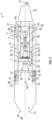
FIG. 2 is a schematic block layout of anexemplary propulsion system 4, according to an aspect of the present disclosure. Thepropulsion system 4 may include aramjet engine 6 and aturbine engine 10. Theturbine engine 10 may be, for example, a turbofan engine or a turbojet engine, as but a few examples. As shown inFIG. 1 ,propulsion system 4 has alongitudinal centerline axis 12 that extends therethrough from anupstream end 34 of thepropulsion system 4 to adownstream end 36 of thepropulsion system 4 for reference purposes. Thelongitudinal centerline axis 12 may also represent a longitudinal centerline axis of theramjet engine 6 and/or a longitudinal centerline axis of theturbine engine 10. Theramjet engine 6 may generally be defined between anouter casing 11 of thepropulsion system 4 and theturbine engine 10. Theramjet engine 6 may extend circumferentially in a circumferential direction C about thelongitudinal centerline axis 12, and theramjet engine 6 may include aramjet inlet portion 7 and aramjet combustor 8. However, theramjet engine 6 need not extend circumferentially about theturbine engine 10, and may be a separate engine defined by another shape (e.g., a square or rectangular shape) extending along at least a portion of the length of theturbine engine 10 that is arranged parallel with theturbine engine 10. For example, theramjet engine 6 may be rectangular shaped arranged either above or below theturbine engine 10 in an over/under configuration of thepropulsion system 4. As will be described in more detail below, a portion of aninlet airflow 13 to thepropulsion system 4 may pass through theramjet inlet portion 7 to theramjet combustor 8, where fuel may be injected by one or more ramjet fuel injectors 9 (two shown inFIG. 1 ) into theramjet combustor 8 to mix with the air and to be ignited and burned to provide ramjet propulsion. - In
FIG. 2 , theturbine engine 10 is depicted as constituting a turbofan engine, and, therefore, the following description will focus on a turbofan engine being included within thepropulsion system 4. Theturbine engine 10 may include afan assembly 14 and acore engine 16 disposed downstream from thefan assembly 14. Thecore engine 16 may generally include a core engineouter casing 18 that defines anannular inlet 20. The core engineouter casing 18 encases, in serial flow relationship, acompressor section 21 that includes a low pressure (LP)compressor 22 and a high pressure (HP)compressor 24, acombustor 26, aturbine section 27 that includes a high pressure (HP)turbine 28 and a low pressure (LP)turbine 30, and a jetexhaust nozzle section 32. The jetexhaust nozzle section 32 may be a shared nozzle that is shared between theturbine engine 10 and theramjet engine 6. A high pressure (HP) shaft assembly 38 drivingly couples the HPturbine 28 to the HPcompressor 24, and a low pressure (LP)shaft assembly 40 drivingly couples theLP turbine 30 to theLP compressor 22. Together, thelow pressure compressor 22, thelow pressure turbine 30, and the lowpressure shaft assembly 40 may be referred to as alow pressure spool 41 that rotate together as one element. Thelow pressure spool 41 may further be coupled to thefan assembly 14 via afan shaft 42, with thefan assembly 14 being arranged upstream of thecompressor section 21. While not shown inFIG. 2 , a reduction gearbox may be implemented within thefan shaft 42 between thelow pressure compressor 22 and thefan assembly 14 so as to function as a speed reducer between thelow pressure spool 41 and thefan assembly 14. Thus, in normal operation of theturbine engine 10, thelow pressure spool 41 drives thefan assembly 14. A fan casing 44 circumferentially surrounds thefan assembly 14 and/or at least a portion of thecore engine 16 so as to define abypass airflow passage 46 therebetween. As an alternative configuration, thefan assembly 14 and thelow pressure compressor 22 may be one and the same such that, for example, thelow pressure compressor 22 may be considered as a multi-stage fan (e.g., a three stage fan). - The
propulsion system 4 is further seen to include an inlet section 48 that includes theramjet inlet portion 7 and a turbineengine inlet portion 50. As will be described below, the inlet section 48 takes in theinlet airflow 13 at apropulsion system inlet 52 and provides theinlet airflow 13 to both theramjet engine 6 and to theturbine engine 10. In theFIG. 2 aspect, the turbineengine inlet portion 50 is shown as including anairflow restriction mechanism 54. Here, in a second (low speed) operating state (e.g., a flight speed of up to Mach 2.5, for example), theairflow restriction mechanism 54 may include a plurality ofairflow inlet doors 56 that can be actuated to an open position as shown inFIG. 2 to allow aturbine inlet airflow 58 from among theinlet airflow 13 to flow through aturbine engine inlet 60 and to thefan assembly 14. - In normal operation of the
turbine engine 10 at the low speed operating state, a first portion of theturbine inlet airflow 58, shown schematically asinlet airflow 62, passes through thefan assembly 14 and into theannular inlet 20 of thecore engine 16. Thelow pressure compressor 22 and thehigh pressure compressor 24 compress theinlet airflow 62 to provide compressed air to thecombustor 26. In thecombustor 26, fuel is injected into the compressed air to generate a fuel/air mixture that is then ignited and burned to generate combustion gases. The combustion gases pass through thehigh pressure turbine 28, thereby supporting operation of thehigh pressure compressor 24, and pass through thelow pressure turbine 30, thereby supporting operation of thelow pressure spool 41. The combustion gases then pass through the jetexhaust nozzle section 32 to provide thrust. A second portion of theturbine inlet airflow 58, shown schematically as aninlet airflow 64, passes through thefan assembly 14 and flows through thebypass airflow passage 46 to provide thrust. - On the other hand, in the low speed operating state, another portion of the
inlet airflow 13 may enter theramjet inlet portion 7 as aramjet inlet airflow 66. In the low speed operating state, theramjet engine 6 may be idle and, therefore, theramjet inlet airflow 66 may merely be a bypass airflow that flows through theramjet combustor 8 without being mixed with fuel. Alternatively, once a predetermined Mach number has been reached (e.g., a Mach number greater than Mach 1) during the low speed operating state, theramjet engine 6 may become operational so as to inject fuel into theramjet combustor 8 by theramjet fuel injector 9 and to ignite the fuel/air mixture within theramjet combustor 8 to generateramjet combustion products 68, thereby providing ramjet thrust. - The
ramjet inlet portion 7 may include aheat exchanger 70 through which fuel passes to obtain gaseous or supercritical fuel components of the fuel that can then be separated into multiple fuel component parts for use in the propulsion system. As but one example, heat generated by compression of theramjet inlet airflow 66 may be used as a heat source to heat the fuel passing through theheat exchanger 70. The heated fuel may then be processed by aseparator 72 so as to obtain multiple different fuel components. For example, when the fuel is ammonia-based, the ammonia-based fuel is heated in theheat exchanger 70 and theseparator 72 can then separate out a first fuel component (e.g., hydrogen) and a second fuel component (e.g., nitrogen) from the heated ammonia-based fuel. The first fuel component (hydrogen) can then be utilized as fuel for theramjet engine 6 and/or to theturbine engine 10. While theseparator 72 is depicted as being adjacent to theheat exchanger 70 within theramjet inlet portion 7, this is merely for reference purposes and the separator may be arranged at other locations within thepropulsion system 4. -
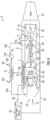
FIG. 3 is a schematic block layout of the propulsion system ofFIG. 2 depicted in a first (high speed) operating state, according to an aspect of the present disclosure. InFIG. 3 , elements that are the same as those ofFIG. 2 are shown with the same reference numerals. InFIG. 3 , the high speed operating state may be an operating state for a flight speed of theaircraft 2 of greater than Mach 2.5, or for a flight speed of theaircraft 2 of up to Mach 5.0, for example. InFIG. 3 , in the high speed operating state, theairflow inlet doors 56 are actuated to a closed state so as to engage with aturbine inlet wall 74, thereby restricting theinlet airflow 13 from passing through theturbine engine inlet 60. Thus, theairflow restriction mechanism 54 is actuated to restrict theinlet airflow 13 from passing therethrough to theturbine engine inlet 60. As will be described in more detail below, in the high speed operating state, upon separating the gaseous or supercritical fuel components to obtain the first fuel component part (e.g., hydrogen), that is a burnable fuel component that may implemented for combustion, and the second fuel component part (e.g., nitrogen), which is a non-burnable fuel component that may implemented for other purposes besides combustion, the second fuel component part (nitrogen) may be provided to theturbine engine inlet 60 viagas nozzles 76. -
FIG. 4 is a schematic block layout of the propulsion system similar to that depicted inFIG. 2 for a low speed operating state, according to another aspect of the present disclosure. InFIG. 4 , elements that are the same as those ofFIG. 2 are shown with the same reference numerals. InFIG. 4 , the turbineengine inlet portion 50 may further include anexpansion turbine 78 upstream of thefan assembly 14. Theexpansion turbine 78 may include a plurality of turbine blades (not shown) that, when airflow passes therethrough, causes theexpansion turbine 78 to rotate. Theexpansion turbine 78 may be coupled/decoupled to/from thefan assembly 14 via a couplingdrive shaft mechanism 80 that is arranged to couple/decouple thefan assembly 14 and theexpansion turbine 78 to/from each other. The couplingdrive shaft mechanism 80 may include, for example, aclutch device 82 that can engage/disengage to couple/decouple theexpansion turbine 78 and thefan assembly 14 to/from each other. Thus, as shown in the low speed operating state ofFIG. 4 , theclutch device 82 may be disengaged so that theexpansion turbine 78 is decoupled from thefan assembly 14, and theairflow restriction mechanism 54 may be in the open state so as to allow theturbine inlet airflow 58 to pass through to theturbine engine inlet 60 and to thefan assembly 14, but to restrict theinlet airflow 13 from entering anexpansion turbine inlet 84 of theexpansion turbine 78. -
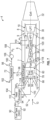
FIG. 5 is a schematic block layout of the propulsion system ofFIG. 4 depicted in a high speed operating state, according to an aspect of the present disclosure. InFIG. 5 , elements that are the same as those ofFIG. 4 are shown with the same reference numerals. In the high speed operating state ofFIG. 5 , theairflow restriction mechanism 54 is actuated to the closed state so that theinlet airflow 13 is restricted from bypassing theexpansion turbine 78, and instead, an expansionturbine inlet airflow 86 is provided to theexpansion turbine 78. The expansionturbine inlet airflow 86 is expanded and cooled by theexpansion turbine 78 and the cooled airflow is provided to theturbine engine inlet 60 and to thefan assembly 14. In addition, the second fuel component (nitrogen) may be provided via thegas nozzles 76 to theexpansion turbine 78. Thus, an inlet flow ofgas 88 enters thecore engine 16, and abypass airflow 89 flows through thebypass airflow passage 46. Further, when theexpansion turbine 78 is made operational to expand and to cool the expansionturbine inlet airflow 86 flowing therethrough, the couplingdrive shaft mechanism 80 may be engaged so as to at least partially drive thelow pressure spool 41, thereby offloading some of the load from thelow pressure turbine 30 required to drive thelow pressure spool 41. -
FIG. 6 is a flow diagram depicting a flow of fuel and gases through various components of thepropulsion system 4 for a high speed operating state, according to an aspect of the present disclosure. InFIG. 6 , the configuration of thepropulsion system 4 is similar to that shown inFIG. 5 , and, therefore, common elements between theFIG. 5 aspect and theFIG. 6 aspect are labeled with the same reference numerals. In the following description ofFIG. 6 to FIG. 9 , thepropulsion system 4 is arranged to utilize an ammonia-based fuel for thepropulsion system 4, where the ammonia-based fuel is processed to obtain a hydrogen fuel component that is utilized for fuel in theramjet engine 6 and/or in theturbine engine 10, and a nitrogen fuel component that can be utilized for cooling and/or as an inlet airflow to theturbine engine 10. As shown inFIG. 6 , thepropulsion system 4 includes afuel storage tank 90 that stores afuel 92, which, again, is an ammonia-based fuel. In the high speed operating state ofFIG. 6 , thefuel 92 is provided via afuel supply line 94 to theheat exchanger 70. As was described above, theheat exchanger 70 may be arranged within theramjet inlet portion 7 of theramjet engine 6. Due to the high temperature of theramjet inlet airflow 66 to theramjet inlet portion 7, theramjet inlet airflow 66 may heat thefuel 92 flowing through theheat exchanger 70 to as much as nine-hundred degrees Fahrenheit. The heating of thefuel 92 may thermally decompose the ammonia-basedfuel 92 into gaseous or supercritical hydrogen (H2) and nitrogen (N2). Alternatively, theheat exchanger 70 may be arranged external to theramjet inlet portion 7, with a ramjet bleed air from theramjet inlet airflow 66 being bled off of theramjet inlet airflow 66 and being provided to theheat exchanger 70 to heat thefuel 92. - The gaseous or supercritical hydrogen and nitrogen are then provided from the
heat exchanger 70 to theseparator 72 via asupply line 96. Theseparator 72 may be a membrane-type gas separator, or a centrifugal type separator, that can separate the gaseous or supercritical hydrogen and nitrogen to be output separately from theseparator 72. Thus, the gaseous or supercritical hydrogen can be output by theseparator 72 as a first fuel component 98 (H2) via anoutput line 100, and as a second fuel component 102 (N2) via asupply line 104. The first fuel component 98 (H2) may then be provided to theramjet fuel injector 9 and/or to thecombustor 26 of theturbine engine 10. Afuel pump 106 and afuel valve 110 may control a flow of thefirst fuel component 98 via afuel supply line 108 to theramjet fuel injector 9 and/or to thecombustor 26 of theturbine engine 10. The second fuel component 102 (N2) may be provided to theturbine engine inlet 60 via thesupply line 104 and thegas nozzles 76. In the case when theexpansion turbine 78 is included in theturbine engine 10, thesecond fuel component 102 may also be provided to an inlet of theexpansion turbine 78. As a result, theturbine engine 10 may continue to operate, along with theramjet engine 6, during the high speed operating state by virtue of thesecond fuel component 102 being input to theturbine engine inlet 60 and the first fuel component 98 (H2) being provided to thecombustor 26 of theturbine engine 10. In addition, the simplified construction of theheat exchanger 70 being located within theramjet inlet portion 7 provides an easier way to heat the ammonia-based fuel to obtain the gaseous or supercritical hydrogen and nitrogen that can then be used to fuel both theramjet engine 6 and theturbine engine 10 without the need for separate fuel tanks holding different fuel types. - While
FIG. 6 generally relates to the high speed operating state, inFIG. 6 , in the low speed operating state, thefuel 92 may be provided from thefuel storage tank 90 to thecombustor 26 of theturbine engine 10 via afuel supply line 93. In the low speed operating state, however, theairflow inlet doors 56 may be actuated to the open position as shown in eitherFIG. 2 orFIG. 4 . -
FIG. 7 is a flow diagram depicting a flow of fuel and gases through various components of thepropulsion system 4 for a high speed operating state, according to another aspect of the present disclosure. InFIG. 7 , the configuration of thepropulsion system 4 is similar to that shown inFIGS. 5 and6 , and, therefore, common elements amongFIG. 5 ,FIG. 6 , andFIG. 7 are labeled with the same reference numerals. The flow of the fuel and gases through the various components of thepropulsion system 4 is similar to that shown inFIG. 6 , butFIG. 7 further includes asecond heat exchanger 112 that is arranged between thefuel storage tank 90 and theheat exchanger 70, and is also arranged between theseparator 72 and theturbine engine inlet 60 of theturbine engine 10. Thus, inFIG. 7 , thefuel storage tank 90 provides thefuel 92 to thesecond heat exchanger 112 via thefuel supply line 94 to pre-heat thefuel 92 before thefuel 92 is provided to theheat exchanger 70 from thesecond heat exchanger 112 via afuel supply line 114. As a heat source for thesecond heat exchanger 112, heat from vehicle thermal loads or heat from engine thermal loads may be provided to thesecond heat exchanger 112 via an aircraft thermal management system (not shown). Other heat sources from various components of theturbine engine 10 may also be implemented to pre-heat thefuel 92 in thesecond heat exchanger 112. The processing by theheat exchanger 70 and theseparator 72 are the same as described above for theFIG. 6 aspect. In theFIG. 7 aspect, however, the second fuel component 102 (N2) from theseparator 72 is provided to thesecond heat exchanger 112, where thesecond fuel component 102 may be utilized by thesecond heat exchanger 112 to pre-heat thefuel 92 passing therethrough. Similarly, thesecond fuel component 102 passing through thesecond heat exchanger 112 may be cooled by virtue of thefuel 92 passing through thesecond heat exchanger 112. In the same manner described above forFIG. 6 , thesecond fuel component 102 is provided to theturbine engine inlet 60 of theturbine engine 10 via anoutput line 116, and thefirst fuel component 98 may be provided to theramjet fuel injector 9 and/or to thecombustor 26 of theturbine engine 10. TheFIG. 7 aspect may further include a ramjetbleed air valve 118 that may provide a ramjet inlet bleed airflow of oxygenated air from theramjet inlet airflow 66 to thecombustor 26 of theturbine engine 10 via a ramjet inlet airflowbleed air passage 120. As a result, thesecond heat exchanger 112 may reduce the amount of heat needed by theheat exchanger 70 to obtain the gaseous or supercritical hydrogen and nitrogen, and may also provide for a coldersecond fuel component 102 being provided to theturbine engine inlet 60. -
FIG. 8 is a flow diagram depicting a flow of fuel and gases through various components of thepropulsion system 4 for a high speed operating state, according to yet another aspect of the present disclosure. InFIG. 8 , the configuration of thepropulsion system 4 is similar to that shown inFIG. 7 , and, therefore, common elements betweenFIG. 7 andFIG. 8 are labeled with the same reference numerals. The flow of the fuel and gases through the various components of thepropulsion system 4 is similar to that shown inFIG. 7 , but theFIG. 8 aspect further includes afuel cell 122 and agas separator 124.Fuel cell 122 may generateelectrical power 125 by inputting hydrogen and oxygen to be processed therewithin to generate theelectrical power 125 and to output water as a byproduct to thesecond heat exchanger 112. Thus, inFIG. 8 , theseparator 72 may output a portion of the first fuel component 98 (H2) to thefuel cell 122 via anoutput line 126 to be utilized by thefuel cell 122. Thegas separator 124 may be an On-Board Oxygen Generation System (OBOGS) that generates oxygen that is output to thefuel cell 122 via anoutput line 130 More particularly, oxygenated air, which may correspond to theramjet inlet airflow 66, may be provided via the ramjetbleed air valve 118 and to ableed air duct 129 to thegas separator 124. Thegas separator 124 may process the oxygenated air to obtain oxygen that is provided to thefuel cell 122 via asupply line 130, and to obtain oxygen depleted air (ODA) that is provided to thesecond heat exchanger 112 via anoutput line 132. Thesecond fuel component 102 from theseparator 72, the water from thefuel cell 122, and the oxygen depleted air from thegas separator 124 are then provided to thesecond heat exchanger 112 and to theturbine engine inlet 60 via theoutput line 116. As a result, thepropulsion system 4 may further be arranged to generate theelectrical power 125 utilizing, at least in part, thefirst fuel component 98. -
FIG. 9 is a flow diagram depicting a flow of fuel and gases through various components of thepropulsion system 4 for a high speed operating state, according to still another aspect of the present disclosure. InFIG. 9 , the configuration of thepropulsion system 4 is similar to that shown inFIG. 7 , and, therefore, common elements between theFIG. 7 aspect and theFIG. 9 aspect are labeled with the same reference numerals. The flow of the fuel and gases through the various components of thepropulsion system 4 is similar to that shown inFIG. 7 , but theFIG. 7 aspect implements theheat exchanger 70 downstream of thecombustor 26, such as downstream of thelow pressure turbine 30 within theturbine engine 10, rather than being arranged within theramjet inlet portion 7 of theramjet engine 6. Theheat exchanger 70 may also be arranged between the combustor 26 and thehigh pressure turbine 28, or may be arranged between thehigh pressure turbine 28 and thelow pressure turbine 30, or at any other location within theturbine section 27. Thus, theFIG. 9 aspect utilizes heat from the combustion gases from theturbine engine 10 to heat thefuel 92 passing through theheat exchanger 70, rather than utilizing heat from theramjet inlet airflow 66 to heat thefuel 92. The flow of fuel and gases inFIG. 9 is otherwise the same as that described above forFIG. 7 . -
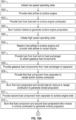
FIG. 10 is a flowchart of process steps for a method of operating a propulsion system, according to an aspect of the present disclosure. The method of operating thepropulsion system 4 may be implemented in any of the foregoing aspects ofFIG. 1 to FIG. 9 . In addition, the method is implemented in apropulsion system 4 that utilizes an ammonia-based fuel. In the method, when thepropulsion system 4 is first started-up, a low speed operating state is initiated instep 1001. In the low speed operating state, instep 1002, as shown inFIG. 2 , for example, theturbine inlet airflow 58 is provided to theturbine engine inlet 60 of theturbine engine 10, and, instep 1003, as was described forFIG. 6 , the fuel 92 (NH3) is provided from thefuel storage tank 90 to theturbine engine combustor 26 via thefuel supply line 93. Instep 1004, and as was described above forFIG. 2 , a fuel/air mixture is burned within thecombustor 26 to generate turbine engine propulsion. Thepropulsion system 4 may operate in the low speed operating state for a flight speed of theaircraft 2 up to, for example, Mach 2.5, and, then instep 1005, the high speed operating state may be initiated. Of course, the high speed operating state may be initiated at other vehicle flight speeds and the present disclosure is not limited to Mach 2.5. For example, the high speed operating state may be initiated at any flight speed between Mach 1.0 and Mach 2.5, or may be initiated at a vehicle flight speed above Mach 2.5. - In initiating the high speed operating state, the
propulsion system 4 may transition from the low speed configuration shown inFIG. 2 to the high speed configuration shown inFIG. 3 , for example. Thus, instep 1006, theairflow inlet doors 56 may be actuated to the closed state so as to restrict theinlet airflow 13 from flowing to theturbine engine inlet 60. In the case when theexpansion turbine 78 is implemented as shown inFIG. 5 , some of theinlet airflow 13 may be permitted to pass through theexpansion turbine 78, but theinlet airflow 13 is otherwise restricted from bypassing theexpansion turbine 78 and flowing directly to theturbine engine inlet 60. In addition, theramjet inlet airflow 66 is provided to theramjet inlet 7. - In
step 1007, thefuel 92 is provided to theheat exchanger 70 to obtain the gaseous or supercritical fuel components (e.g., H2 and N2) of thefuel 92. This process may be as described above for theFIG. 6 aspect in which thefuel 92 is provided from thefuel storage tank 90 directly to theheat exchanger 70 to be heated by theramjet inlet airflow 66, or may be as described above for theFIG. 7 aspect, where thefuel 92 is provided to thesecond heat exchanger 112 and then to theheat exchanger 70. As was described above for bothFIGS. 6 and7 , the heating of thefuel 92 in theheat exchanger 70 results in obtaining the gaseous fuel components of thefuel 92, including the first fuel component 98 (H2) and the second fuel component 102 (N2). Instep 1008, the fuel components (98, 102) are provided from theheat exchanger 70 to theseparator 72. As was described above, theseparator 72 separates the fuel components (98, 102), and instep 1009, the first fuel component 98 (H2) is provided to theramjet combustor 8 and/or to theturbine engine combustor 26. Instep 1010, thefirst fuel component 98 is injected into theramjet combustor 8 by theramjet fuel injector 9, and theramjet inlet airflow 66 is mixed in theramjet combustor 8 with thefirst fuel component 98. The fuel/air mixture is then ignited and burned within theramjet combustor 8 to generate ramjet propulsion. - As was described above with regard to the
FIG. 3 aspect and theFIG. 6 aspect, for example, in the high speed operating state, theturbine engine 10 may also be made operational along with theramjet engine 6. Thus, when theturbine engine 10 is made operational in the high speed operating state along with theramjet engine 6, thefirst fuel component 98 may also be provided to thecombustor 26 of the turbine engine 10 (step 1009). In addition, instep 1011, the second fuel component 102 (N2) may be provided from theseparator 72 to theturbine engine inlet 60 as was discussed forFIG. 6 . The second fuel component 102 (N2) flows through theturbine engine inlet 60 and is utilized by theturbine engine 10 in the same manner as theturbine inlet airflow 58 is utilized byturbine engine 10 as described forFIG. 2 . Thus, instep 1012, thesecond fuel component 102 mixes in thecombustor 26 with thefirst fuel component 98, and the mixture is burned to generate turbine engine propulsion. - In the
FIG. 8 aspect, the additional components of thefuel cell 122 and thegas separator 124 were shown as being optionally included within thepropulsion system 4. Thus, in the case when thefuel cell 122 and thegas separator 124 are implemented, the method may further include, instep 1013, theseparator 72 providing the first fuel component 98 (H2) to thefuel cell 122. In addition, as was described above forFIG. 8 , instep 1014, ramjet bleed air is provided to the gas separator 124 (described above as an On-Board Oxygen Generating System) to obtain oxygen and oxygen depleted air. Instep 1015, the oxygen obtained by thegas separator 124 is provided to thefuel cell 122, and may also be provided to thecombustor 26 of theturbine engine 10. Instep 1016, thefuel cell 122 utilizes the first fuel component 98 (H2) and the oxygen from thegas separator 124 to generate theelectrical power 125. - Each of the foregoing aspects provide for a
propulsion system 4 that combines aramjet engine 6 and aturbine engine 10 for high speed operations, where an ammonia-based fuel is implemented to operate by theramjet engine 6 and theturbine engine 10. By processing the ammonia-based fuel to separate the fuel into gaseous or supercritical components, each of which can be used for different purposes within thepropulsion system 4, the need for separate fuel tanks to accommodate separate fuels can be eliminated. In addition, thepropulsion system 4 can operate better through a transitional speed range (e.g., a speed range from Mach 2.0 to Mach 5.0) by virtue of both theramjet engine 6 and theturbine engine 10 being able to be operational through the speed range. - Further aspects of the present disclosure are provided by the subject matter of the following clauses.
- A propulsion system comprises a turbine engine, a ramjet engine, a fuel storage tank storing a fuel, a heat exchanger through which the fuel passes to obtain gaseous fuel components of the fuel, and a separator that separates the gaseous fuel components into a first fuel component and a second fuel component, the first fuel component being provided to the ramjet engine for ramjet combustion in a first operating state of the propulsion system.
- The propulsion system according to the preceding clause, the heat exchanger being provided within a ramjet inlet portion of the ramjet engine, and a ramjet inlet airflow to the ramjet inlet portion is utilized by the heat exchanger to heat the fuel passing through the heat exchanger.
- The propulsion system according to any preceding clause, the heat exchanger being provided downstream of a combustor of the turbine engine, and combustion products of the turbine engine passing through the heat exchanger are utilized by the heat exchanger to heat the fuel passing through the heat exchanger.
- The propulsion system according to any preceding clause, the fuel being an ammonia-based fuel, the first fuel component is hydrogen, and the second fuel component is nitrogen.
- The propulsion system according to any preceding clause, the fuel being provided from the fuel storage tank to the turbine engine in a second operating state, the ramjet engine being non-operational in the second operating state.
- The propulsion system according to any preceding clause, the first fuel component being further provided to the turbine engine for turbine combustion in the first operating state, and the second fuel component is provided to an inlet of the turbine engine for the turbine combustion in the first operating state.
- The propulsion system according to any preceding clause, in the first operating state, both the turbine engine and the ramjet engine operating simultaneously.
- The propulsion system according to any preceding clause, further comprising a second heat exchanger arranged upstream of the heat exchanger and arranged downstream of the separator.
- The propulsion system according to any preceding clause, in the first operating state, the fuel being provided to the second heat exchanger to obtain a pre-heated fuel, the pre-heated fuel is provided to the heat exchanger to obtain the heated fuel, the second fuel component is provided from the separator to the second heat exchanger to obtain a cooled second fuel component, and the cooled second fuel component is provided to an inlet of the turbine engine for turbine combustion.
- The propulsion system according to any preceding clause, in the first operating state, the first fuel component being provided from the separator to a ramjet combustor of the ramjet engine for ramjet combustion, and the first fuel component is provided to a turbine combustor of the turbine engine for turbine combustion.
- The propulsion system according to any preceding clause, the ramjet engine further including at least one ramjet inlet airflow bleed passage that provides a ramjet inlet bleed airflow to the turbine combustor for the turbine combustion.
- The propulsion system according to any preceding clause, further comprising a fuel cell, a gas separator, and at least one ramjet inlet airflow bleed passage arranged in a ramjet inlet portion of the ramjet engine, the fuel cell being arranged in flow communication with the separator, with the second heat exchanger, and with the gas separator, the gas separator being arranged in flow communication with the at least one ramjet inlet airflow bleed passage, with the fuel cell, with the second heat exchanger, and with the turbine combustor of the turbine engine.
- The propulsion system according to any preceding clause, the separator providing the first fuel component to the fuel cell, the gas separator provides oxygen to the fuel cell and to the turbine combustor, and provides an oxygen depleted gas to the second heat exchanger, and the fuel cell generates electrical power and provides a byproduct to the second heat exchanger.
- The propulsion system according to any preceding clause, the turbine engine including a turbine inlet portion, the turbine inlet portion including an inlet airflow restriction mechanism that, in the first operating state, is actuated to restrict an inlet airflow to the turbine engine, and, in a second operating state, is actuated to permit the inlet airflow to the turbine engine.
- The propulsion system according to any preceding clause, the turbine inlet portion including an expansion turbine arranged upstream of a fan assembly of the turbine engine, the separator providing the second fuel component to the expansion turbine in the first operating state.
- A method of operating a propulsion system, the propulsion system including (a) a turbine engine, (b) a ramjet engine, (c) a fuel storage tank storing a fuel, (d) a heat exchanger through which the fuel passes to obtain a gaseous fuel components of the fuel, and (e) a separator that separates the gaseous fuel components into a first fuel component and a second fuel component, the method comprising, in a first operating state of the propulsion system, (i) restricting, via an inlet airflow restriction mechanism, an inlet airflow to a turbine engine inlet of the turbine engine, (ii) providing a ramjet inlet airflow to a ramjet inlet of the ramjet engine, (iii) providing the fuel to the heat exchanger to obtain gaseous fuel components of the fuel, (iv) providing the gaseous fuel components from the heat exchanger to the separator to obtain the first fuel component and the second fuel component, (v) providing the first fuel component to a ramjet combustor of the ramjet engine, and (vi) burning a second fuel/gas mixture within the ramjet combustor to generate ramjet engine propulsion, and, in a second operating state of the propulsion system, (vii) providing an inlet airflow to an inlet of the turbine engine, (viii) providing the fuel from the fuel storage tank to a turbine combustor of the turbine engine, and (ix) burning a first fuel/gas mixture within the turbine combustor to generate turbine engine propulsion.
- The method according to any preceding clause, the heat exchanger being provided in one of the ramjet inlet such that the ramjet inlet airflow is utilized by the heat exchanger to obtain the gaseous fuel components, or is provided downstream of the turbine combustor such that the heat exchanger utilizes combustion products of the turbine combustion to obtain the gaseous fuel components.
- The method according to any preceding clause, in the first operating state, the first fuel component being further provided from the separator to the turbine combustor, and the second fuel component is provided to the inlet of the turbine engine, the turbine engine burning a third fuel/gas mixture within the turbine combustor to generate turbine engine propulsion.
- The method according to any preceding clause, the propulsion system further including (f) a second heat exchanger arranged upstream of the heat exchanger and downstream of the separator, and, further, in the first operating state of the propulsion system, (x) providing the fuel to the second heat exchanger to obtain a pre-heated fuel, (xi) providing the pre-heated fuel to the heat exchanger to obtain the heated fuel, (xii) providing the second fuel component from the separator to the second heat exchanger to obtain a cooled second fuel component, and (xiii) providing the cooled second fuel component from the second heat exchanger to the inlet of the turbine engine.
- The propulsion system according to any preceding clause, the propulsion system further including (g) a fuel cell, (h) a gas separator, and (j) at least one ramjet inlet airflow bleed passage arranged in an inlet duct of the ramjet engine, the method further comprising (xiv) providing the first fuel component from the separator to the fuel cell, (xv) providing oxygenated air from the at least ramjet inlet airflow bleed passage to the gas separator, (xvi) providing oxygen from the gas separator to the fuel cell, (xvii) generating, by the fuel cell, electrical power, (xviii) providing the oxygen from the gas separator to the turbine combustor, and (xix) providing oxygen depleted air from the gas separator to the second heat exchanger.
- Although the foregoing description is directed to some exemplary embodiments of the present disclosure, other variations and modifications will be apparent to those skilled in the art, and may be made without departing from the spirit or the scope of the disclosure. Moreover, features described in connection with one embodiment of the present disclosure may be used in conjunction with other embodiments, even if not explicitly stated above.
Claims (15)
- A propulsion system (4) comprising:a turbine engine (10);a ramjet engine (6);a fuel storage tank (90) storing a fuel (92);a heat exchanger (70) through which the fuel passes to obtain gaseous fuel components (98, 102) of the fuel (92); anda separator (72) that separates the gaseous fuel components (98, 102) into a first fuel component (98) and a second fuel component (102),wherein the first fuel component (98) is provided to the ramjet engine (6) for ramjet combustion in a first operating state (1005) of the propulsion system (4).
- The propulsion system (4) according to claim 1, wherein the heat exchanger (70) is provided within a ramjet inlet portion (7) of the ramjet engine (6), and a ramjet inlet airflow (66) to the ramjet inlet portion (7) is utilized by the heat exchanger (70) to heat the fuel (92) passing through the heat exchanger (70).
- The propulsion system (4) according to any preceding claim, wherein the heat exchanger (70) is provided downstream of a combustor (26) of the turbine engine (10), and combustion products of the turbine engine (10) passing through the heat exchanger (70) are utilized by the heat exchanger (70) to heat the fuel (92) passing through the heat exchanger (70).
- The propulsion system (4) according to any preceding claim, wherein the fuel (92) is an ammonia-based fuel, the first fuel component (98) is hydrogen, and the second fuel component (102) is nitrogen.
- The propulsion system (4) according to any preceding claim, wherein the fuel (92) is provided from the fuel storage tank (90) to the turbine engine (10) in a second operating state (1001), the ramjet engine (6) being non-operational in the second operating state (1001).
- The propulsion system (4) according to any preceding claim, wherein the first fuel component (98) is further provided to the turbine engine (10) for turbine combustion in the first operating state (1005), and the second fuel component (102) is provided to an inlet (60) of the turbine engine (10) for the turbine combustion in the first operating state (1005), and alternatively,
wherein, in the first operating state (1105), both the turbine engine (10) and the ramjet engine (6) operate simultaneously. - The propulsion system (4) according to any preceding claim, further comprising a second heat exchanger (112) arranged upstream of the heat exchanger (70) and arranged downstream of the separator (72), and alternatively,wherein, in the first operating state (1005), the fuel (92) is provided to the second heat exchanger (112) to obtain a pre-heated fuel, the pre-heated fuel is provided to the heat exchanger (70) to obtain the heated fuel, the second fuel component (102) is provided from the separator (72) to the second heat exchanger (112) to obtain a cooled second fuel component (102), and the cooled second fuel component (102) is provided to an inlet (60) of the turbine engine (10) for turbine combustion, and alternatively,wherein, in the first operating state (1005), the first fuel component (98) is provided from the separator (72) to a ramjet combustor (8) of the ramjet engine (6) for ramjet combustion, and the first fuel component (98) is provided to a turbine combustor (26) of the turbine engine (10) for turbine combustion.
- The propulsion system (4) according to claim 7, wherein the ramjet engine (6) further includes at least one ramjet inlet airflow bleed passage (120) that provides a ramjet inlet bleed airflow to the turbine combustor (26) for the turbine combustion.
- The propulsion system (4) according to claim 7 or 8, further comprising a fuel cell (122), a gas separator (124), and at least one ramjet inlet airflow bleed passage (120) arranged in a ramjet inlet portion (7) of the ramjet engine (6), the fuel cell (122) being arranged in flow communication with the separator (72), with the second heat exchanger (112), and with the gas separator (124), the gas separator (124) being arranged in flow communication with the at least one ramjet inlet airflow (66) bleed passage, with the fuel cell (122), with the second heat exchanger (112), and with the turbine combustor (26) of the turbine engine (10), and alternatively,
wherein the separator (72) provides the first fuel component (98) to the fuel cell (122), the gas separator (124) provides oxygen to the fuel cell (122) and to the turbine combustor (26), and provides an oxygen depleted gas to the second heat exchanger (112), and the fuel cell (122) generates electrical power and provides a byproduct to the second heat exchanger (112). - The propulsion system (4) according to any preceding claim, wherein the turbine engine (10) includes a turbine inlet portion (50), the turbine inlet portion (50) including an inlet airflow restriction mechanism (54) that, in the first operating state (1005), is actuated to restrict an inlet airflow (13) to the turbine engine (10), and, in a second operating state (1001), is actuated to permit the inlet airflow (5) to the turbine engine (10), and alternatively,
wherein the turbine inlet portion (50) includes an expansion turbine (78) arranged upstream of a fan assembly (14) of the turbine engine (10), the separator (72) providing the second fuel component (102) to the expansion turbine (78) in the first operating state (1005). - A method of operating the propulsion system (4) of any preceding claim, the method comprising:in a first operating state (1005) of the propulsion system (4):(i) restricting (1006), via an inlet airflow restriction mechanism (54), an inlet airflow (13) to a turbine engine inlet (60) of the turbine engine (10);(ii) providing (1006) a ramjet inlet airflow (66) to a ramjet inlet of the ramjet engine (6);(iii) providing (1007) the fuel (92) to the heat exchanger (70) to obtain gaseous fuel components (98, 102) of the fuel (92);(iv) providing (1008) the gaseous fuel components (98, 102) from the heat exchanger (70) to the separator (72) to obtain the first fuel component (98) and the second fuel component (102);(v) providing (1009) the first fuel component (98) to a ramjet combustor (8) of the ramjet engine (6); and(vi) burning (1010) a second fuel/gas mixture within the ramjet combustor (8) to generate ramjet engine (6) propulsion, andin a second operating state (1001) of the propulsion system (4):(vii) providing (1002) an inlet airflow (88) to an inlet (60) of the turbine engine (10);(viii) providing (1003) the fuel (92) from the fuel storage tank (90) to a turbine combustor (26) of the turbine engine (10); and(ix) burning (1004) a first fuel/gas mixture within the turbine combustor (26) to generate turbine engine (10) propulsion.
- The method according to claim 11, wherein the heat exchanger (70) is provided in one of the ramjet inlet portion (7) such that the ramjet inlet airflow (66) is utilized by the heat exchanger (70) to obtain the gaseous fuel components (98, 102), or is provided downstream of the turbine combustor (26) such that the heat exchanger (70) utilizes combustion products of the turbine combustion to obtain the gaseous fuel components (98, 102).
- The method according to claim 11 or 12, wherein, in the first operating state (1005), the first fuel component (98) is further provided (1009) from the separator (72) to the turbine combustor (26), and the second fuel component (102) is provided to the inlet (60) of the turbine engine (10), the turbine engine (10) burning a third fuel/gas mixture within the turbine combustor (26) to generate turbine engine (10) propulsion.
- The method according to claim 13, wherein the propulsion system (4) further includes (f) a second heat exchanger (112) arranged upstream of the heat exchanger (70) and downstream of the separator (72), and, further, in the first operating state (1005) of the propulsion system (4):(x) providing the fuel (92) to the second heat exchanger (112) to obtain a pre-heated fuel;(xi) providing the pre-heated fuel to the heat exchanger (70) to obtain the heated fuel;(xii) providing the second fuel component (102) from the separator (72) to the second heat exchanger (112) to obtain a cooled second fuel component (102); and(xiii) providing the cooled second fuel component (102) from the second heat exchanger (112) to the inlet (60) of the turbine engine (10).
- The propulsion system (4) according to claim 14, wherein the propulsion system (4) further includes (g) a fuel cell (122), (h) a gas separator (124), and (j) at least one ramjet inlet airflow bleed passage (120) arranged in a ramjet inlet portion (7) of the ramjet engine (6), the method further comprising:(xiv) providing the first fuel component (98) from the separator (72) to the fuel cell (122);(xv) providing oxygenated air from the at least ramjet inlet airflow (5, 88) bleed passage to the gas separator (124);(xvi) providing oxygen from the gas separator (124) to the fuel cell (122);(xvii) generating, by the fuel cell (122), electrical power;(xviii) providing the oxygen from the gas separator (124) to the turbine combustor (26); and(xix) providing oxygen depleted air from the gas separator (124) to the second heat exchanger (112).
Applications Claiming Priority (1)
| Application Number | Priority Date | Filing Date | Title |
|---|---|---|---|
| US18/065,143 US12116956B2 (en) | 2022-12-13 | 2022-12-13 | Ammonia based hydrogen powered combined propulsion system |
Publications (1)
| Publication Number | Publication Date |
|---|---|
| EP4386188A1 true EP4386188A1 (en) | 2024-06-19 |
Family
ID=88833734
Family Applications (1)
| Application Number | Title | Priority Date | Filing Date |
|---|---|---|---|
| EP23209636.2A Pending EP4386188A1 (en) | 2022-12-13 | 2023-11-14 | Ammonia based hydrogen powered combined propulsion system |
Country Status (2)
| Country | Link |
|---|---|
| US (1) | US12116956B2 (en) |
| EP (1) | EP4386188A1 (en) |
Families Citing this family (2)
| Publication number | Priority date | Publication date | Assignee | Title |
|---|---|---|---|---|
| GB2608643B (en) * | 2021-07-09 | 2025-01-08 | Reaction Engines Ltd | Thermally integrated ammonia fuelled engine |
| CN119244373B (en) * | 2024-09-29 | 2025-06-20 | 中国科学院力学研究所 | A hybrid supersonic engine using ammonia as a working fluid |
Citations (5)
| Publication number | Priority date | Publication date | Assignee | Title |
|---|---|---|---|---|
| FR2687433A1 (en) * | 1992-02-14 | 1993-08-20 | Onera (Off Nat Aerospatiale) | Propulsion unit with reversed components, with modulated supply |
| US5394685A (en) * | 1990-11-14 | 1995-03-07 | United Technologies Corporation | Method and apparatus to enhance combustion rates and extend extinction limits in high speed propulsion units |
| US20100242437A1 (en) * | 2009-03-25 | 2010-09-30 | United Technologies Corporation | Fuel-cooled flexible heat exchanger with thermoelectric device compression |
| WO2022101608A1 (en) * | 2020-11-12 | 2022-05-19 | University College Cardiff Consultants Limited | Combustor systems and methods |
| CN114922740A (en) * | 2022-05-31 | 2022-08-19 | 中国科学院力学研究所 | A wide-range air-breathing combined aerospace engine and its working method and application |
Family Cites Families (29)
| Publication number | Priority date | Publication date | Assignee | Title |
|---|---|---|---|---|
| GB800871A (en) | 1954-10-22 | 1958-09-03 | Berger Michel | Jet reaction units |
| US3777487A (en) | 1961-02-09 | 1973-12-11 | Garrett Corp | Method and apparatus for reaction propulsion |
| US3198604A (en) * | 1962-05-28 | 1965-08-03 | Engelhard Ind Inc | Hydrogen generating system |
| US3740949A (en) * | 1963-11-20 | 1973-06-26 | Texaco Inc | Fuel cooled ram air reaction propulsion engine |
| US3705496A (en) * | 1963-11-20 | 1972-12-12 | Texaco Experiment Inc | Reaction propulsion engine and method of operation |
| US3733826A (en) * | 1964-02-10 | 1973-05-22 | Texaco Experiment Inc | Fuel cooled ram air reaction propulsion engine |
| US3811280A (en) | 1967-10-06 | 1974-05-21 | Us Army | Process of using storable propellant fuels in supersonic combustion ramjets |
| US3792584A (en) * | 1972-02-16 | 1974-02-19 | Boeing Co | Increased or variable bypass ratio engines |
| US4667900A (en) * | 1981-03-05 | 1987-05-26 | Kyusik Kim | Ram constriction vane diffuser for jet engine |
| US5085048A (en) | 1990-02-28 | 1992-02-04 | General Electric Company | Scramjet including integrated inlet and combustor |
| US5216876A (en) * | 1990-11-05 | 1993-06-08 | Consolidated Natural Gas Service Company, Inc. | Method for reducing nitrogen oxide emissions from gas turbines |
| US5459994A (en) * | 1993-05-28 | 1995-10-24 | Praxair Technology, Inc. | Gas turbine-air separation plant combination |
| US6644015B2 (en) * | 2001-10-29 | 2003-11-11 | Hmx, Inc. | Turbojet with precompressor injected oxidizer |
| US20150315971A1 (en) * | 2013-10-21 | 2015-11-05 | Government Of The United States As Represented By The Secretary Of The Air Force | High-speed vehicle power and thermal management system and methods of use therefor |
| US10590849B2 (en) * | 2014-03-27 | 2020-03-17 | General Electric Company | High speed propulsion system with inlet cooling |
| US20180017017A1 (en) * | 2016-07-12 | 2018-01-18 | Rolls Royce North American Technologies Inc. | Ramburning engine with inlet turbine |
| US20190293024A1 (en) | 2018-02-23 | 2019-09-26 | Global Reach Aerospace LLC | Hydrogen-fueled supersonic turboramjet engine |
| CN110203882B (en) * | 2019-06-20 | 2023-07-07 | 福大紫金氢能科技股份有限公司 | A kind of ammonia decomposition device and system and hydrogen production method |
| GB2591253A (en) | 2020-01-22 | 2021-07-28 | Airbus Operations Ltd | An aircraft fuselage |
| GB202016379D0 (en) | 2020-10-15 | 2020-12-02 | Airbus Operations Ltd | Dual fuel aircraft |
| US20220162989A1 (en) | 2020-11-20 | 2022-05-26 | Raytheon Technologies Corporation | Engine using cracked ammonia fuel |
| US12006865B2 (en) | 2020-11-20 | 2024-06-11 | Rtx Corporation | Cracking and separation of ammonia fuel |
| GB2601367A (en) | 2020-11-27 | 2022-06-01 | Reaction Engines Ltd | Engines |
| US20220389884A1 (en) * | 2021-06-04 | 2022-12-08 | Raytheon Technologies Corporation | Variable cycle jet engine |
| FR3127269B1 (en) | 2021-09-17 | 2023-09-08 | Safran Aircraft Engines | AIRCRAFT TURBOMACHINE WITH OFF-AXLE PROPELLER |
| FR3130897B1 (en) | 2021-12-17 | 2023-11-24 | Safran Aircraft Engines | AIRCRAFT TURBOMACHINE |
| FR3130896B1 (en) | 2021-12-17 | 2023-12-15 | Safran Aircraft Engines | AIRCRAFT TURBOMACHINE |
| FR3133368B1 (en) | 2022-03-11 | 2024-08-02 | Safran Aircraft Engines | PROPELLER ASSEMBLY FOR AN AIRCRAFT |
| FR3133367B1 (en) | 2022-03-11 | 2024-08-23 | Safran Aircraft Engines | AERONAUTICAL PROPELLER |
-
2022
- 2022-12-13 US US18/065,143 patent/US12116956B2/en active Active
-
2023
- 2023-11-14 EP EP23209636.2A patent/EP4386188A1/en active Pending
Patent Citations (5)
| Publication number | Priority date | Publication date | Assignee | Title |
|---|---|---|---|---|
| US5394685A (en) * | 1990-11-14 | 1995-03-07 | United Technologies Corporation | Method and apparatus to enhance combustion rates and extend extinction limits in high speed propulsion units |
| FR2687433A1 (en) * | 1992-02-14 | 1993-08-20 | Onera (Off Nat Aerospatiale) | Propulsion unit with reversed components, with modulated supply |
| US20100242437A1 (en) * | 2009-03-25 | 2010-09-30 | United Technologies Corporation | Fuel-cooled flexible heat exchanger with thermoelectric device compression |
| WO2022101608A1 (en) * | 2020-11-12 | 2022-05-19 | University College Cardiff Consultants Limited | Combustor systems and methods |
| CN114922740A (en) * | 2022-05-31 | 2022-08-19 | 中国科学院力学研究所 | A wide-range air-breathing combined aerospace engine and its working method and application |
Also Published As
| Publication number | Publication date |
|---|---|
| US20240191675A1 (en) | 2024-06-13 |
| US12116956B2 (en) | 2024-10-15 |
Similar Documents
| Publication | Publication Date | Title |
|---|---|---|
| AU2023278050B2 (en) | Combustor for a gas turbine engine | |
| US5392595A (en) | Endothermic fuel energy management system | |
| US10641169B2 (en) | Hybrid combustor assembly and method of operation | |
| CN109028142B (en) | Propulsion system and method of operating the same | |
| AU2021245108A1 (en) | Micro-turbine gas generator and propulsive system | |
| EP4386188A1 (en) | Ammonia based hydrogen powered combined propulsion system | |
| US20220364513A1 (en) | Turbine engines having hydrogen fuel systems | |
| EP4198281B1 (en) | System for producing diluent for a gas turbine engine | |
| EP4215730B1 (en) | Hydrogen powered geared turbo fan engine with an off-set reduced core | |
| US11131461B2 (en) | Effervescent atomizing structure and method of operation for rotating detonation propulsion system | |
| EP4303418B1 (en) | Hybrid electric power for turbine engines having hydrogen fuel systems | |
| US20240191674A1 (en) | Propulsion system using ramjet bleed air for gas turbine combustion | |
| US12392295B2 (en) | Aircraft propulsion system | |
| WO2022051849A1 (en) | Turboramjet engine | |
| US20240418127A1 (en) | Gaseous fuel and liquid water injection for turbine engine | |
| EP4431718A1 (en) | Selective steam distribution to steam cooled zones in a turbine engine | |
| EP4636234A1 (en) | Monitoring fuel phase in aircraft powerplant fuel system | |
| VISEK, JR | Design concept for LOX/hydrocarbon tripropellant booster engine |
Legal Events
| Date | Code | Title | Description |
|---|---|---|---|
| PUAI | Public reference made under article 153(3) epc to a published international application that has entered the european phase |
Free format text: ORIGINAL CODE: 0009012 |
|
| STAA | Information on the status of an ep patent application or granted ep patent |
Free format text: STATUS: THE APPLICATION HAS BEEN PUBLISHED |
|
| AK | Designated contracting states |
Kind code of ref document: A1 Designated state(s): AL AT BE BG CH CY CZ DE DK EE ES FI FR GB GR HR HU IE IS IT LI LT LU LV MC ME MK MT NL NO PL PT RO RS SE SI SK SM TR |
|
| STAA | Information on the status of an ep patent application or granted ep patent |
Free format text: STATUS: REQUEST FOR EXAMINATION WAS MADE |
|
| 17P | Request for examination filed |
Effective date: 20241127 |
|
| RBV | Designated contracting states (corrected) |
Designated state(s): AL AT BE BG CH CY CZ DE DK EE ES FI FR GB GR HR HU IE IS IT LI LT LU LV MC ME MK MT NL NO PL PT RO RS SE SI SK SM TR |