EP4386187A2 - Apparatus - Google Patents
Apparatus Download PDFInfo
- Publication number
- EP4386187A2 EP4386187A2 EP24174090.1A EP24174090A EP4386187A2 EP 4386187 A2 EP4386187 A2 EP 4386187A2 EP 24174090 A EP24174090 A EP 24174090A EP 4386187 A2 EP4386187 A2 EP 4386187A2
- Authority
- EP
- European Patent Office
- Prior art keywords
- fluid
- container
- phase change
- heat exchange
- change material
- Prior art date
- Legal status (The legal status is an assumption and is not a legal conclusion. Google has not performed a legal analysis and makes no representation as to the accuracy of the status listed.)
- Pending
Links
Images

Classifications
-
- F—MECHANICAL ENGINEERING; LIGHTING; HEATING; WEAPONS; BLASTING
- F01—MACHINES OR ENGINES IN GENERAL; ENGINE PLANTS IN GENERAL; STEAM ENGINES
- F01P—COOLING OF MACHINES OR ENGINES IN GENERAL; COOLING OF INTERNAL-COMBUSTION ENGINES
- F01P3/00—Liquid cooling
- F01P3/20—Cooling circuits not specific to a single part of engine or machine
-
- B—PERFORMING OPERATIONS; TRANSPORTING
- B60—VEHICLES IN GENERAL
- B60H—ARRANGEMENTS OF HEATING, COOLING, VENTILATING OR OTHER AIR-TREATING DEVICES SPECIALLY ADAPTED FOR PASSENGER OR GOODS SPACES OF VEHICLES
- B60H1/00—Heating, cooling or ventilating devices
- B60H1/00492—Heating, cooling or ventilating devices comprising regenerative heating or cooling means, e.g. heat accumulators
-
- F—MECHANICAL ENGINEERING; LIGHTING; HEATING; WEAPONS; BLASTING
- F01—MACHINES OR ENGINES IN GENERAL; ENGINE PLANTS IN GENERAL; STEAM ENGINES
- F01M—LUBRICATING OF MACHINES OR ENGINES IN GENERAL; LUBRICATING INTERNAL COMBUSTION ENGINES; CRANKCASE VENTILATING
- F01M11/00—Component parts, details or accessories, not provided for in, or of interest apart from, groups F01M1/00 - F01M9/00
- F01M11/04—Filling or draining lubricant of or from machines or engines
- F01M11/0458—Lubricant filling and draining
-
- F—MECHANICAL ENGINEERING; LIGHTING; HEATING; WEAPONS; BLASTING
- F01—MACHINES OR ENGINES IN GENERAL; ENGINE PLANTS IN GENERAL; STEAM ENGINES
- F01M—LUBRICATING OF MACHINES OR ENGINES IN GENERAL; LUBRICATING INTERNAL COMBUSTION ENGINES; CRANKCASE VENTILATING
- F01M5/00—Heating, cooling, or controlling temperature of lubricant; Lubrication means facilitating engine starting
- F01M5/001—Heating
-
- F—MECHANICAL ENGINEERING; LIGHTING; HEATING; WEAPONS; BLASTING
- F02—COMBUSTION ENGINES; HOT-GAS OR COMBUSTION-PRODUCT ENGINE PLANTS
- F02N—STARTING OF COMBUSTION ENGINES; STARTING AIDS FOR SUCH ENGINES, NOT OTHERWISE PROVIDED FOR
- F02N19/00—Starting aids for combustion engines, not otherwise provided for
- F02N19/02—Aiding engine start by thermal means, e.g. using lighted wicks
- F02N19/04—Aiding engine start by thermal means, e.g. using lighted wicks by heating of fluids used in engines
- F02N19/10—Aiding engine start by thermal means, e.g. using lighted wicks by heating of fluids used in engines by heating of engine coolants
-
- F—MECHANICAL ENGINEERING; LIGHTING; HEATING; WEAPONS; BLASTING
- F01—MACHINES OR ENGINES IN GENERAL; ENGINE PLANTS IN GENERAL; STEAM ENGINES
- F01M—LUBRICATING OF MACHINES OR ENGINES IN GENERAL; LUBRICATING INTERNAL COMBUSTION ENGINES; CRANKCASE VENTILATING
- F01M11/00—Component parts, details or accessories, not provided for in, or of interest apart from, groups F01M1/00 - F01M9/00
- F01M11/04—Filling or draining lubricant of or from machines or engines
- F01M2011/0483—Filling or draining lubricant of or from machines or engines with a lubricant cartridge for facilitating the change
-
- F—MECHANICAL ENGINEERING; LIGHTING; HEATING; WEAPONS; BLASTING
- F01—MACHINES OR ENGINES IN GENERAL; ENGINE PLANTS IN GENERAL; STEAM ENGINES
- F01M—LUBRICATING OF MACHINES OR ENGINES IN GENERAL; LUBRICATING INTERNAL COMBUSTION ENGINES; CRANKCASE VENTILATING
- F01M5/00—Heating, cooling, or controlling temperature of lubricant; Lubrication means facilitating engine starting
-
- F—MECHANICAL ENGINEERING; LIGHTING; HEATING; WEAPONS; BLASTING
- F01—MACHINES OR ENGINES IN GENERAL; ENGINE PLANTS IN GENERAL; STEAM ENGINES
- F01P—COOLING OF MACHINES OR ENGINES IN GENERAL; COOLING OF INTERNAL-COMBUSTION ENGINES
- F01P11/00—Component parts, details, or accessories not provided for in, or of interest apart from, groups F01P1/00 - F01P9/00
- F01P11/14—Indicating devices; Other safety devices
- F01P2011/205—Indicating devices; Other safety devices using heat-accumulators
-
- F—MECHANICAL ENGINEERING; LIGHTING; HEATING; WEAPONS; BLASTING
- F28—HEAT EXCHANGE IN GENERAL
- F28D—HEAT-EXCHANGE APPARATUS, NOT PROVIDED FOR IN ANOTHER SUBCLASS, IN WHICH THE HEAT-EXCHANGE MEDIA DO NOT COME INTO DIRECT CONTACT
- F28D20/00—Heat storage plants or apparatus in general; Regenerative heat-exchange apparatus not covered by groups F28D17/00 or F28D19/00
- F28D20/0034—Heat storage plants or apparatus in general; Regenerative heat-exchange apparatus not covered by groups F28D17/00 or F28D19/00 using liquid heat storage material
-
- F—MECHANICAL ENGINEERING; LIGHTING; HEATING; WEAPONS; BLASTING
- F28—HEAT EXCHANGE IN GENERAL
- F28D—HEAT-EXCHANGE APPARATUS, NOT PROVIDED FOR IN ANOTHER SUBCLASS, IN WHICH THE HEAT-EXCHANGE MEDIA DO NOT COME INTO DIRECT CONTACT
- F28D20/00—Heat storage plants or apparatus in general; Regenerative heat-exchange apparatus not covered by groups F28D17/00 or F28D19/00
- F28D20/02—Heat storage plants or apparatus in general; Regenerative heat-exchange apparatus not covered by groups F28D17/00 or F28D19/00 using latent heat
- F28D20/028—Control arrangements therefor
-
- F—MECHANICAL ENGINEERING; LIGHTING; HEATING; WEAPONS; BLASTING
- F28—HEAT EXCHANGE IN GENERAL
- F28D—HEAT-EXCHANGE APPARATUS, NOT PROVIDED FOR IN ANOTHER SUBCLASS, IN WHICH THE HEAT-EXCHANGE MEDIA DO NOT COME INTO DIRECT CONTACT
- F28D20/00—Heat storage plants or apparatus in general; Regenerative heat-exchange apparatus not covered by groups F28D17/00 or F28D19/00
- F28D2020/0004—Particular heat storage apparatus
- F28D2020/0026—Particular heat storage apparatus the heat storage material being enclosed in mobile containers for transporting thermal energy
-
- Y—GENERAL TAGGING OF NEW TECHNOLOGICAL DEVELOPMENTS; GENERAL TAGGING OF CROSS-SECTIONAL TECHNOLOGIES SPANNING OVER SEVERAL SECTIONS OF THE IPC; TECHNICAL SUBJECTS COVERED BY FORMER USPC CROSS-REFERENCE ART COLLECTIONS [XRACs] AND DIGESTS
- Y02—TECHNOLOGIES OR APPLICATIONS FOR MITIGATION OR ADAPTATION AGAINST CLIMATE CHANGE
- Y02E—REDUCTION OF GREENHOUSE GAS [GHG] EMISSIONS, RELATED TO ENERGY GENERATION, TRANSMISSION OR DISTRIBUTION
- Y02E60/00—Enabling technologies; Technologies with a potential or indirect contribution to GHG emissions mitigation
- Y02E60/14—Thermal energy storage
Definitions
- This invention relates to a heat exchanger for equipment, such as a vehicle, which may be coupled to a fluid system such as a fluid container.
- This invention also relates to associated apparatus and equipment such as a vehicle.
- Such fluids often are consumed during operation of the engine.
- the properties of such fluids may also degrade with time so that their performance deteriorates, resulting in a need for replacement with fresh fluid.
- Such replacement may be an involved and time-consuming process.
- replacement of engine lubricating oil in a vehicle engine usually involves draining the lubricating oil from the engine sump.
- the process may also involve removing and replacing the engine oil filter.
- Such a procedure usually requires access to the engine sump drain plug and oil filter from the underside of the engine, may require the use of hand tools and usually requires a suitable collection method for the drained lubricating oil.
- the phase change material 11 is a latent heat accumulator and is configured to change state from solid to liquid to store heat received through the heat exchange interface 12 from the fluid 33 flowing within, into and/or from the replaceable fluid container 3, for example when the fluid 33 has been heated up, e.g. by an engine 22 of the vehicle 2 and/or an engine temperature regulating system, e.g. when the engine 22 and/or the fluid 33 are at a nominal operating temperature.
- the phase change material 11, once in a liquid phase is configured to store the heat, e.g. after the engine 22 is shut down and e.g. up until a cold restart of the engine 22 and/or up until the fluid 33 has cooled down.
- the heat stored in the phase change material 11 may be accessed through the heat exchange interface 12 by the fluid 33 flowing within, into and/or from the replaceable fluid container 3, to provide fast warm up of the fluid 33, e.g. to reduce friction, emissions (such as CO2) and/or fuel consumption in case the fluid 33 is a lubricating oil.
- the phase change material 11 may change state from liquid to solid when heat is transferred to the fluid 33 flowing within, into and/or from the replaceable fluid container 3, and the change from solid state to liquid state described above can be repeated.
- non-destructive manner means that integrity of the container is not altered, except maybe for breakage and/or destruction of seals (such as seals on fluid ports) or of other disposable elements of the container.
- the fluid 33 may not flow in the pipework 121a, and the surface area of the heat exchange interface 12a is limited to the first part, e.g. to the wall 131 only.
- the wall 131 may be a thermal insulator so that heat exchange between the phase change material 11a and the fluid 33 is minimal.
- the phase change material 11, once in a liquid phase, is configured to store the heat, e.g. after the engine 22 is shut down and e.g. up until a cold restart of the engine 22 and/or up until the fluid 33 has cooled down.
- the heat exchange interface 12b comprises pipework 121b.
- the pipework 121b is provided within the receptacle 13b, with extremities 122b and 123b in fluidic communication with a fluid path 133 of the fluid circulation system 23 located in the dock 4.
- the pipework 121b may enlarge the surface area of the heat exchange interface 12b compared to a situation where the heat exchange interface 12b only comprises, e.g. a wall 132 in proximity with the fluid path 133 of the fluid circulation system 23 located in the dock 4.
- the heat exchanger 1 comprises two three-way valves 14b, e.g. provided at the extremities 122b and 123b of the pipework 121b and on the fluid circulation system 23, e.g. on the fluid outlet for supplying fluid from the replaceable fluid container 3 to the fluid circulation system 23.
- the two three-way valves 14b are configured to control a flow of the fluid 33 in the heat exchange interface 12b in the dock 4, as explained below.
- the fluid 33 may not flow in the pipework 121b, and the surface area of the heat exchange interface 12b is limited, e.g. to only e.g. the wall 132.
- the wall 132 may be a thermal insulator so that heat exchange between the phase change material 11b and the fluid 33 is minimal.
- the heat exchanger 12 may comprise a single valve or more than two valves.
- the one or more valves 14a and/or 14b may be configured to be controlled by a controller 25 of the vehicle 2.
- the heat exchanger 1 for the vehicle 2 comprises:
- the heat exchanger 1 for the vehicle 2 comprises the heat exchange interface 12b configured to be located in the dock 4.
- the phase change material 11b located in the dock 4 is contained in a receptacle 13b, and the phase change material 11c located on the engine 22 is contained in a receptacle 13c.
- the receptacle 13b is housed within the dock 4.
- the heat exchange interface 12b comprises pipework 121b.
- the pipework 121b is provided within the receptacle 13b, with extremities 122b and 123b in fluidic communication with the fluid path 133 of the fluid circulation system 23 located in the dock 4, and the fluid 33 from the replaceable fluid container 3 flows through the pipework 121b of the heat exchange interface 12b.
- the heat exchanger 1 further comprises a pump 15c provided on the fluid circulation system 23, for example a pump for supply of fluid from the replaceable fluid container 3 to the fluid circulation system 23.
- the pump 15c is also configured to control a flow of the fluid 33 in the heat exchange interface 12b in the dock 4, e.g. by regulating the flow of the fluid 33 in the heat exchange interface 12b.
- the pump 15c may be controlled by the controller 25.
- the receptacle 13b and the receptacle 13c are in fluidic communication with pipework 18 and 19 configured to allow circulation of at least the phase change material 11c, in a liquid form, between the receptacle 13b and the receptacle 13c. Additionally or alternatively, the pipework 18 and 19 is also configured to allow circulation of the phase change material 11b, in a liquid form, between the receptacle 13b and the receptacle 13c.
- the receptacle 13c located in the engine 22 increases the amount of phase change material available for the heat exchange interface 12b located in the dock 4, compared to a situation with the receptacle 13b only.
- the heat exchanger 1 further comprises a pump 16 and a control valve 17 provided on the pipework 18.
- the pump 16 and the control valve 17 are configured to control a flow of at least the phase change material 11c, once in a liquid form, in the heat exchange interface 12b located in the dock 4, e.g. by regulating the flow of the liquid phase change material 1 1c in the heat exchange interface 12b, e.g. in the receptacle 13b.
- the pump 16 and/or valve 17 may be controlled by the controller 25.
- the heat exchanger 1 may comprise only a pump 16 and no control valve 17, or only a control valve 17 and no pump 16, or no pump 16 and no control valve 17.
- the pipework 18 and 19 is also configured to allow circulation of the phase change material 11b, in a liquid form, around the receptacle 13b, for heat exchange between the phase change material 11b and the phase change material 11c.
- phase change material 11b and the phase change material 11c may be the same type of phase change material, e.g. both Barium Hydroxide as a non-limiting example, or may be different respective types of phase change materials.
- the heat exchanger 1 may be configured to be controlled by the controller 25 of the vehicle 2 such that heat is exchanged between the phase change material 11 and the fluid 33 of the replaceable fluid container before ignition of the vehicle 2.
- at least one of the pumps allowing the fluid 33 to flow within, into and/or from a replaceable fluid container 3 may be operated before ignition of the vehicle 2, such that:
- the receptacle 13 containing the phase change material 11 may comprise thermal insulation located or at least partly located around the phase change material 11.
- the dock 4 and the replaceable fluid container 3 are illustrated as not being a part of the vehicle 2. It should be understood that, in some examples, the dock 4 and/or the replaceable fluid container 3 may form, at least partly, part of the vehicle 2. In such examples, the dock 4 and/or the replaceable fluid container 3 may be located under a bonnet of the vehicle 2.
- a replaceable fluid container could be used in relation to a wide range of equipment, such equipment including but not being limited to the vehicle described above.
- the replaceable fluid container could find applications in relation to various static or mobile pieces of equipment, e.g. to supply the fluid to the equipment or to at least a region of the equipment, for example in relation to equipment including:
- apparatus comprising the heat exchanger according to any aspect of the disclosure may comprise, at least partly, or may be:
- phase change material may comprise:
- phase change materials are envisaged.
- the controller 25 may form, at least partly, part of the engine control unit (ECU) of the vehicle. Additionally or alternatively, in some examples, the controller 25 may form, at least partly, part of the dock 4, such as part of a data transceiver of the dock 4. In some examples, the data transceiver of the dock may be configured to receive data from a data provider of the container 3 and provide data to the vehicle, e.g. after a processing by a controller. Additionally or alternatively, in some examples, the controller 25 may form, at least partly, part of the container 3, such as part of the data provider of the container 3. In some examples, the controller 25 may not be a single entity, but may be distributed in different parts of the vehicle 2, and/or in different parts of the dock 4, and/or in different parts of the container 3.
- ECU engine control unit
- the controller 25 may comprise a memory and a processor.
- the processor associated with the controller 25 may be a controller such as a microcontroller or the like with the controller managing communication (which may be encrypted communication) with the container 3 and/or with the vehicle 2, for example with a communications (e.g. controller area network (CAN) bus that couples with the engine control unit (ECU) or engine management system.
- a communications e.g. controller area network (CAN) bus that couples with the engine control unit (ECU) or engine management system.
- the container 3 may be a container for a fluid which is a liquid.
- suitable liquids include engine lubricating oil and heat exchange fluid for an electric engine.
- the data provider of the replaceable fluid container may comprise a processor.
- the data provider may comprise a memory for storing data describing the fluid in the replaceable fluid container.
- the memory may store data including at least one of: the grade of the fluid, the type of fluid, the date on which the container was filled or refilled, a unique identifier of the container, an indication of whether the container is new, or has previously been refilled or replaced, an indication of the vehicle mileage, the number of times the container has been refilled or reused, and the total mileage for which the container has been used.
- the processor associated with the controller 25 may also read and/or write data to a memory or data store of the data provider of the container.
- This data may be encrypted and may include vehicle data and sensor parameters.
- Data storage may be carried out at start-up and periodically as a vehicle carrying the container accumulates miles of distance travelled and duration of engine running.
- the container 3 may be provided as a self-contained container containing fresh, refreshed or unused lubricating oil which may easily replace a container (e.g. on the dock 4) which is empty or contains used or spent lubricating oil.
- the container 3 may contain a filter. If the container 3 also comprises the filter, the filter is also replaced together with the spent or used lubricating oil.
- a replaceable fluid container 3 containing spent or used lubricating oil retained in fluidic communication with the vehicle engine fluid circulation system 23 may be disconnected from the vehicle engine fluid circulation system 23, removed from the vehicle and replaced by a container containing fresh, refreshed or unused lubricating oil and if present a fresh, renewed or new filter.
- a part of the replaceable fluid container 3 may be separated from another part of the container, and a new part may be attached to the other part. Parts may thus be re-used and/or recycled.
- the receptacle 13 may be a replaceable element in the context of the fluid container, i.e.:
- the receptacle may be within a same replaceable fluid container through a life cycle of the replaceable fluid container.
- the vehicle may comprise at least one electric drivetrain. In some examples, the vehicle may be a hybrid vehicle.
- the vehicle comprises a battery.
- the battery of the vehicle may be configured to provide at least a part of an electrical power required for operation of the electric drivetrain and/or the pumps and/or valves.
- the engine lubricating oil may comprise at least one base stock and at least one engine lubricating oil additive.
- Suitable base stocks include bio-derived base stocks, mineral oil derived base stocks, synthetic base stocks and semi synthetic base stocks.
- Suitable engine lubricating oil additives are known in the art.
- the additives may be organic and/or inorganic compounds.
- the engine lubricating oil may comprise about 60 to 90 % by weight in total of base stocks and about 40 to 10 % by weight additives.
- the engine lubricating oil may be a lubricating oil for an internal combustion engine.
- the engine lubricating oil may be a lubricating oil for a spark ignition internal combustion engine.
- the engine lubricating oil may be a lubricating oil for a compression ignition internal combustion engine.
- the engine lubricating oil may be a mono-viscosity grade or a multi-viscosity grade engine lubricating oil.
- the engine lubricating oil may be a single purpose lubricating oil or a multi-purpose lubricating oil.
- the container may be a container for heat exchange fluid for an electric engine.
- the container may contain heat exchange fluid for an electric engine.
- the container may be provided as a self-contained container containing fresh, refreshed or unused heat exchange fluid for an electric engine which may easily replace a container (e.g. on the dock 4) which can be empty or can contain used or spent heat exchange fluid. If the container also comprises a filter, this also is replaced together with the spent or used heat exchange fluid.
- Electric engines may require heat exchange fluid to heat the engine and/or cool the engine. This may depend upon the operating cycle of the engine. Electric engines may also require a reservoir of heat exchange fluid.
- the replaceable fluid container may provide a heat storage container in which heat exchange fluid may be stored for use to heat the electric engine when required.
- the replaceable fluid container may provide a container for storage of coolant at a temperature below the operating temperature of the engine for use to cool the electric engine when required.
- Suitable heat exchange fluids for electric engines may be aqueous or non-aqueous fluids.
- Suitable heat exchange fluids for electric engines may comprise organic and/or non-organic performance boosting additives.
- Suitable heat exchange fluids may be man-made or bio-derived, for example Betaine.
- the heat exchange fluids may have fire retarding characteristics and/or hydraulic characteristics.
- Suitable heat exchange fluids include phase change fluids.
- Suitable heat exchange fluids include molten metals or salts.
- Suitable heat exchange fluids include nanofluids. Nanofluids comprise nanoparticles suspended in a base fluid, which may be solid, liquid or gas.
- Suitable heat exchange fluids include gases and liquids.
- Suitable heat exchange fluids include liquefied gases.
- the fluid may be any type of fluid circulated in the engine and/or circulated in any fluid circulation system associated with the engine (that is the fluid is not necessarily circulated in the engine) to support a function of the engine and/or the vehicle.
- the function may be an ancillary function of the engine.
- the fluid may be a de-icer and/or any hydraulic fluid such as a fluid used in braking systems, and/or a pneumatic fluid, a washer fluid, a fuel additive or any other fluid associated with any function of the engine and/or the vehicle.
- the disclosure may be applied to vehicles having a "dry sump” or a “wet sump”.
- One or more containers may be inserted and/or seated and/or docked in the dock.
- the dock may be a physical structure in which the container is seated and then docked.
- the dock may simply be a fluid coupling or couplings of the engine fluid circulation system for coupling to the at least one fluid port of the container.
- the fluid ports may comprise fluid couplings, which may be self-sealing.
- Suitable vehicles include motorcycles, earthmoving vehicles, mining vehicles, heavy duty vehicles and passenger cars.
- Powered water-borne vessels are also envisaged as vehicles, including yachts, motor boats (for example with an outboard motor), pleasure craft, jet-skis and fishing vessels.
- Applications of the disclosure are envisaged for parts only of the vehicles, for example parts including one or more moving parts (for example a gearbox).
- the container may be manufactured from metal and/or plastics material. Suitable materials include reinforced thermoplastics material which for example, may be suitable for operation at temperatures of up to 150 °C for extended periods of time.
- the container may comprise at least one trade mark, logo, product information, advertising information, other distinguishing feature or combination thereof.
- the container may be printed and/or labelled with at least one trade mark, logo, product information, advertising information, other distinguishing feature or combination thereof. This may have an advantage of deterring counterfeiting.
- the container may be of a single colour or multi-coloured.
- the trademark, logo or other distinguishing feature may be of the same colour and/or material as the rest of the container or a different colour and/or material as the rest of the container.
- the container may be provided with packaging, such as a box or a pallet.
- the packaging may be provided for a plurality of containers, and in some examples a box and/or a pallet may be provided for a plurality of containers.
- one or more memory elements can store data and/or program instructions used to implement the operations described herein.
- Embodiments of the disclosure provide tangible, non-transitory storage media comprising program instructions operable to program a processor to perform any one or more of the methods described and/or claimed herein and/or to provide data processing apparatus as described and/or claimed herein.
- controllers and/or processors which may be provided by fixed logic such as assemblies of logic gates or programmable logic such as software and/or computer program instructions executed by a processor.
- programmable logic include programmable processors, programmable digital logic (e.g., a field programmable gate array (FPGA), an erasable programmable read only memory (EPROM), an electrically erasable programmable read only memory (EEPROM)), an application specific integrated circuit, ASIC, or any other kind of digital logic, software, code, electronic instructions, flash memory, optical disks, CD-ROMs, DVD ROMs, magnetic or optical cards, other types of machine-readable mediums suitable for storing electronic instructions, or any suitable combination thereof.
- FPGA field programmable gate array
- EPROM erasable programmable read only memory
- EEPROM electrically erasable programmable read only memory
- ASIC application specific integrated circuit
Landscapes
- Engineering & Computer Science (AREA)
- Mechanical Engineering (AREA)
- General Engineering & Computer Science (AREA)
- Chemical & Material Sciences (AREA)
- Combustion & Propulsion (AREA)
- Thermal Sciences (AREA)
- Physics & Mathematics (AREA)
- Lubrication Of Internal Combustion Engines (AREA)
- Heat-Exchange Devices With Radiators And Conduit Assemblies (AREA)
- Physical Or Chemical Processes And Apparatus (AREA)
- Air-Conditioning For Vehicles (AREA)
- Other Investigation Or Analysis Of Materials By Electrical Means (AREA)
- Materials For Photolithography (AREA)
- Heating, Cooling, Or Curing Plastics Or The Like In General (AREA)
Abstract
Description
- This invention relates to a heat exchanger for equipment, such as a vehicle, which may be coupled to a fluid system such as a fluid container. This invention also relates to associated apparatus and equipment such as a vehicle.
- Many vehicle engines use one or more fluids for their operation. Such fluids are often liquids. For example, internal combustion engines use liquid lubricating oil. Also, electric engines use fluids which can provide heat exchange functionality, for example to cool the engine and/or to heat the engine, and/or to cool and heat the engine during different operating conditions. The heat exchange functionality of the fluids may be provided in addition to other functions (such as a primary function) which may include for example charge conduction and/or electrical connectivity. Such fluids are generally held in reservoirs associated with the engine and may require periodic replacement.
- Such fluids often are consumed during operation of the engine. The properties of such fluids may also degrade with time so that their performance deteriorates, resulting in a need for replacement with fresh fluid. Such replacement may be an involved and time-consuming process. For example, replacement of engine lubricating oil in a vehicle engine usually involves draining the lubricating oil from the engine sump. The process may also involve removing and replacing the engine oil filter. Such a procedure usually requires access to the engine sump drain plug and oil filter from the underside of the engine, may require the use of hand tools and usually requires a suitable collection method for the drained lubricating oil.
- Aspects and embodiments of the present disclosure are directed to a heat exchanger for equipment, such as a vehicle, which may be coupled to a fluid system such as a fluid container. Aspects and embodiments of the present disclosure are directed to associated apparatus comprising a heat exchanger according to any aspect of the disclosure and to equipment, such as a vehicle, comprising a heat exchanger according to any aspect of the disclosure.
- Aspects of the invention are recited in the independent claims and preferred features are recited in the dependent claims.
- Some embodiments will now be described, by way of example only, with reference to the accompanying drawings, in which:
-
Figure 1 shows a schematic illustration of a first example heat exchanger; -
Figure 2 shows a schematic illustration of a second example heat exchanger; -
Figure 3 shows a schematic illustration of a third example heat exchanger; -
Figure 4 shows a schematic illustration of a fourth example heat exchanger; and -
Figure 5 shows a schematic illustration of a fifth example heat exchanger. - Embodiments of the present disclosure provide, as shown for example in
Figures 1 to 5 , aheat exchanger 1 for avehicle 2. In the examples illustrated byFigures 1 to 5 , areplaceable fluid container 3 for thevehicle 2 is coupled to adock 4. In the examples illustrated byFigures 1 to 5 , thereplaceable fluid container 3 comprises afluid 33 within thereplaceable fluid container 3 and also comprises at least onefluid port fluid circulation system 23 of thevehicle 2. Thefluid port 31 is afluid inlet port 31 of thereplaceable fluid container 3 and thefluid port 32 is afluid outlet port 32 of thereplaceable fluid container 3. - In the examples of
Figures 1 to 5 , theheat exchanger 1 comprises at least onephase change material 11, and at least oneheat exchange interface 12. - In the examples of
Figures 1 to 5 , theheat exchange interface 12 is configured for heat exchange between thephase change material 11 and thefluid 33 flowing within, into and/or from thereplaceable fluid container 3. - The
phase change material 11 is a latent heat accumulator and is configured to change state from solid to liquid to store heat received through theheat exchange interface 12 from thefluid 33 flowing within, into and/or from thereplaceable fluid container 3, for example when thefluid 33 has been heated up, e.g. by anengine 22 of thevehicle 2 and/or an engine temperature regulating system, e.g. when theengine 22 and/or thefluid 33 are at a nominal operating temperature. Thephase change material 11, once in a liquid phase, is configured to store the heat, e.g. after theengine 22 is shut down and e.g. up until a cold restart of theengine 22 and/or up until thefluid 33 has cooled down. The heat stored in thephase change material 11 may be accessed through theheat exchange interface 12 by thefluid 33 flowing within, into and/or from thereplaceable fluid container 3, to provide fast warm up of thefluid 33, e.g. to reduce friction, emissions (such as CO2) and/or fuel consumption in case thefluid 33 is a lubricating oil. In some examples, depending on the amount of heat transferred from thephase change material 11 to thefluid 33, thephase change material 11 may change state from liquid to solid when heat is transferred to thefluid 33 flowing within, into and/or from thereplaceable fluid container 3, and the change from solid state to liquid state described above can be repeated. - In the present disclosure, "replaceable" means that:
- the container can be supplied full with fresh and/or unused fluid, and/or
- the container can be coupled to, i.e. e.g. inserted and/or seated and/or docked in the dock, in a non-destructive manner, and/or
- the container can be removed from the dock, in a non-destructive manner, i.e. in a manner which enables its re-coupling should that be desired, and/or
- the same (for example after having been refilled) or another (for example full and/or new) container can be re-coupled to the dock, e.g. re-inserted and/or re-seated and/or re-docked in the dock, in a non-destructive manner.
- It should be understood that the term "replaceable" means that the container may be "replaced" by another new container and/or the same container after having been refilled (in other words the replaceable container may be "refillable") which may be re-coupled to the dock, e.g. re-inserted in the dock.
- In the present disclosure, "in a non-destructive manner" means that integrity of the container is not altered, except maybe for breakage and/or destruction of seals (such as seals on fluid ports) or of other disposable elements of the container.
- It should be understood that the term "configured to be" encompasses the meaning "is" .
- In the examples of
Figures 1 to 5 , the flow offluid 33 to thereplaceable fluid container 3 is caused by apump 231 of thefluid circulation system 23 of thevehicle 2. In the examples ofFigures 1 to 5 , thefluid circulation system 23 of thevehicle 2 also comprises asump 232, e.g. a fluid sump, such as a lubricating oil sump. In the examples ofFigures 1 to 5 , thepump 231 may be a scavenging pump. In the examples ofFigure 1 to 4 , the fluid supply from thecontainer 3 to thefluid circulation system 23 may be provided e.g. by gravity, but in the example illustrated byFigure 5 , the fluid supply may be performed by apump 15c of thefluid circulation system 23 of thevehicle 2. - In the example illustrated by
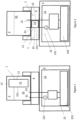
Figure 1 , theheat exchanger 1 for thevehicle 2 comprises thephase change material 11 and theheat exchange interface 12. - In the example illustrated by
Figure 1 , thephase change material 11 is configured to be located in thereplaceable fluid container 3. In the example illustrated byFigure 1 , theheat exchange interface 12 is also configured to be located in thereplaceable fluid container 3. - In the example illustrated by
Figure 1 , thephase change material 11 is contained in areceptacle 13. In the example illustrated byFigure 1 , thereceptacle 13 is housed within thereplaceable fluid container 3. In the example illustrated byFigure 1 , theheat exchange interface 12 is provided on thereceptacle 13 containing thephase change material 11, e.g. on at least onewall 131 of thereceptacle 13. - In the example of
Figure 1 , theheat exchange interface 12 is configured for heat exchange between thephase change material 11 and thefluid 33 at least flowing within thereplaceable fluid container 3, e.g. when fluid flows to or from thereplaceable fluid container 3. - The example illustrated by
Figure 2 comprises elements of the example illustrated byFigure 1 . The elements in common in the examples illustrated byFigure 2 and byFigure 1 will not be described here for the sake of conciseness and clarity. - In the example illustrated by
Figure 2 , theheat exchanger 1 for thevehicle 2 comprises thephase change material 11 and theheat exchange interface 12.
In the example illustrated byFigure 2 , thephase change material 11 is configured to be located in thedock 4. In the example illustrated byFigure 2 , theheat exchange interface 12 is also configured to be located in thedock 4. - In the example illustrated by
Figure 2 , thephase change material 11 is contained in areceptacle 13. In the example illustrated byFigure 2 , thereceptacle 13 is housed within thedock 4 and located in proximity with thefluid circulation system 23 of thevehicle 2. In the example illustrated byFigure 2 , theheat exchange interface 12 is provided on thereceptacle 13 containing thephase change material 11. Additionally or alternatively, at least a part of thereceptacle 13 containing thephase change material 11 is configured to form at least a part of thefluid circulation system 23, e.g. awall 131 of thereceptacle 13 may form part of thefluid circulation system 23. - In the example of
Figure 2 , theheat exchange interface 12 is configured for heat exchange between thephase change material 11 and thefluid 33 at least flowing to or from thereplaceable fluid container 3, e.g. when fluid flows through thefluid port fluid circulation system 23. - The example illustrated by
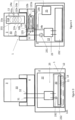
Figure 3 comprises elements of the example illustrated byFigure 1 . The elements in common in the examples illustrated byFigure 3 and byFigure 1 will not be described here for the sake of conciseness and clarity. - In the example illustrated by
Figure 3 , theheat exchanger 1 for thevehicle 2 comprises thephase change material 11 and theheat exchange interface 12. - In the example illustrated by
Figure 3 , thephase change material 11 is configured to be located in a part of thevehicle 2 other than thedock 4. In the example illustrated byFigure 3 , theheat exchange interface 12 is also configured to be located in a part of thevehicle 2 other than thedock 4. In the example illustrated byFigure 3 , thephase change material 11 and theheat exchange interface 12 are configured to be located, at least partly, in thesump 232 of theengine 22 of thevehicle 2. - In the example illustrated by
Figure 3 , thephase change material 11 is contained in areceptacle 13. In the example illustrated byFigure 3 , thereceptacle 13 is housed within thesump 232 of thefluid circulation system 23 of thevehicle 2. In the example ofFigure 3 , thepump 231 may be a scavenging pump. In the example ofFigure 3 , the fluid supply from thecontainer 3 to thefluid circulation system 23 may be provided e.g. by gravity, but embodiments with at least one supply pump in the fluid circulation system are also envisaged. - In the example illustrated by
Figure 3 , theheat exchange interface 12 is provided on thereceptacle 13 containing thephase change material 11 and which is in contact with the fluid 33 in thesump 232 when the fluid is in circulation in thefluid circulation system 23. Additionally or alternatively, at least a part of thereceptacle 13 containing thephase change material 11 is configured to form at least a part of thesump 232 of thefluid circulation system 23, e.g. awall 131 of thereceptacle 13 may form part of thefluid circulation system 23, as illustrated by the dotted lines in the example illustrated byFigure 3 . - In the example of
Figure 3 , theheat exchange interface 12 is configured for heat exchange between thephase change material 11 and the fluid 33 at least flowing in thesump 232 when fluid is flowing to or from the replaceablefluid container 3 in thefluid circulation system 23. - The example illustrated by
Figure 4 comprises elements of the example illustrated byFigure 1 . The elements in common in the examples illustrated byFigure 4 and byFigure 1 will not be described here for the sake of conciseness and clarity. - In the example illustrated by
Figure 4 , theheat exchanger 1 for thevehicle 2 comprises: - the
phase change material 11a configured to be located in the replaceablefluid container 3; and - the
phase change material 11b configured to be located in thedock 4. - In the example illustrated by
Figure 4 , theheat exchanger 1 for thevehicle 2 also comprises: - the
heat exchange interface 12a configured to be located in the replaceablefluid container 3; and - the
heat exchange interface 12b configured to be located in thedock 4. - In the example illustrated by
Figure 4 , thephase change material 11a located in the replaceablefluid container 3 and thephase change material 11b located in thedock 4 are contained inreceptacles Figure 4 , thereceptacle 13a is housed within the replaceablefluid container 3. In the example illustrated byFigure 4 , a first part of theheat exchange interface 12a is provided on thereceptacle 13a containing thephase change material 1 1a, e.g. on at least onewall 131 of thereceptacle 13a. - In the example illustrated by
Figure 4 , theheat exchange interface 12a also comprises a secondpart comprising pipework 121a. In the example illustrated byFigure 4 , thepipework 121a is provided within thereceptacle 13a, withextremities fluid container 3. In the example illustrated byFigure 4 , thepipework 121a may enlarge the surface area of theheat exchange interface 12a compared to a situation where theheat exchange interface 12a only comprises thewall 131. - In the example illustrated by
Figure 4 , theheat exchanger 1 comprises twocontrol valves 14a, e.g. provided at theextremities pipework 121a. The twocontrol valves 14a are configured to control a flow of the fluid 33 in theheat exchange interface 12a in the replaceablefluid container 3, as explained below. - In a closed configuration of the
valves 14a, the fluid 33 may not flow in thepipework 121a, and the surface area of theheat exchange interface 12a is limited to the first part, e.g. to thewall 131 only. In some examples, thewall 131 may be a thermal insulator so that heat exchange between thephase change material 11a and the fluid 33 is minimal. Thephase change material 11, once in a liquid phase, is configured to store the heat, e.g. after theengine 22 is shut down and e.g. up until a cold restart of theengine 22 and/or up until the fluid 33 has cooled down. - In an open configuration of the
valves 14a, the fluid 33 may flow in thepipework 121a, thereby enlarging the surface area of theheat exchange interface 12a compared to the situation described with reference to the closed configuration of thevalves 14a. It should be understood that in some examples theheat exchanger 1 may not comprise thecontrol valves 14a. - In the example illustrated by
Figure 4 , theheat exchange interface 12b comprisespipework 121b. In the example illustrated byFigure 4 , thepipework 121b is provided within thereceptacle 13b, withextremities fluid path 133 of thefluid circulation system 23 located in thedock 4. In the example illustrated byFigure 4 , thepipework 121b may enlarge the surface area of theheat exchange interface 12b compared to a situation where theheat exchange interface 12b only comprises, e.g. awall 132 in proximity with thefluid path 133 of thefluid circulation system 23 located in thedock 4. - In the example illustrated by
Figure 4 , theheat exchanger 1 comprises two three-way valves 14b, e.g. provided at theextremities pipework 121b and on thefluid circulation system 23, e.g. on the fluid outlet for supplying fluid from the replaceablefluid container 3 to thefluid circulation system 23. The two three-way valves 14b are configured to control a flow of the fluid 33 in theheat exchange interface 12b in thedock 4, as explained below. - In a first configuration of the
valves 14b, illustrated by arrow A, the fluid 33 may not flow in thepipework 121b, and the surface area of theheat exchange interface 12b is limited, e.g. to only e.g. thewall 132. In some examples, thewall 132 may be a thermal insulator so that heat exchange between thephase change material 11b and the fluid 33 is minimal. - In a second configuration of the
valves 14b, illustrated by arrow B, the fluid 33 may flow in thepipework 121b, thereby enlarging the surface area of theheat exchange interface 12b compared to the situation described with reference to the first configuration of thevalves 14b. - It should be understood that other numbers of valves are envisaged, and the
heat exchanger 12 may comprise a single valve or more than two valves. - The one or
more valves 14a and/or 14b may be configured to be controlled by acontroller 25 of thevehicle 2. - The example illustrated by
Figure 5 comprises elements of the example illustrated byFigure 1 . The elements in common in the examples illustrated byFigure 5 and byFigure 1 will not be described here for the sake of conciseness and clarity. - In the example illustrated by
Figure 5 , theheat exchanger 1 for thevehicle 2 comprises: - the
phase change material 11b, configured to be located in thedock 4; and - the
phase change material 11c configured to be located in a part of thevehicle 2, other than thedock 4, not necessarily in thesump 232 of thefluid circulation system 23. In the example illustrated byFigure 5 , thephase change material 11c is configured to be located, e.g. on theengine 22 of thevehicle 2, but other location may be envisaged. - In the example illustrated by
Figure 5 , theheat exchanger 1 for thevehicle 2 comprises theheat exchange interface 12b configured to be located in thedock 4. - In the example illustrated by
Figure 5 , thephase change material 11b located in thedock 4 is contained in areceptacle 13b, and thephase change material 11c located on theengine 22 is contained in areceptacle 13c. In the example illustrated byFigure 5 , thereceptacle 13b is housed within thedock 4. - In the example illustrated by
Figure 5 , theheat exchange interface 12b comprisespipework 121b. In the example illustrated byFigure 5 , thepipework 121b is provided within thereceptacle 13b, withextremities fluid path 133 of thefluid circulation system 23 located in thedock 4, and the fluid 33 from the replaceablefluid container 3 flows through thepipework 121b of theheat exchange interface 12b. - In the example illustrated by
Figure 5 , theheat exchanger 1 further comprises apump 15c provided on thefluid circulation system 23, for example a pump for supply of fluid from the replaceablefluid container 3 to thefluid circulation system 23. Thepump 15c is also configured to control a flow of the fluid 33 in theheat exchange interface 12b in thedock 4, e.g. by regulating the flow of the fluid 33 in theheat exchange interface 12b. In some examples, thepump 15c may be controlled by thecontroller 25. - In the example illustrated by
Figure 5 , thereceptacle 13b and thereceptacle 13c are in fluidic communication withpipework phase change material 11c, in a liquid form, between thereceptacle 13b and thereceptacle 13c. Additionally or alternatively, thepipework phase change material 11b, in a liquid form, between thereceptacle 13b and thereceptacle 13c. Thereceptacle 13c located in theengine 22 increases the amount of phase change material available for theheat exchange interface 12b located in thedock 4, compared to a situation with thereceptacle 13b only. - In the example illustrated by
Figure 5 , theheat exchanger 1 further comprises apump 16 and acontrol valve 17 provided on thepipework 18. Thepump 16 and thecontrol valve 17 are configured to control a flow of at least thephase change material 11c, once in a liquid form, in theheat exchange interface 12b located in thedock 4, e.g. by regulating the flow of the liquidphase change material 1 1c in theheat exchange interface 12b, e.g. in thereceptacle 13b. - In some examples, the
pump 16 and/orvalve 17 may be controlled by thecontroller 25. - It should be understood that, in some embodiments, the
heat exchanger 1 may comprise only apump 16 and nocontrol valve 17, or only acontrol valve 17 and nopump 16, or nopump 16 and nocontrol valve 17. - Additionally or alternatively, the
pipework phase change material 11b, in a liquid form, around thereceptacle 13b, for heat exchange between thephase change material 11b and thephase change material 11c. - In some examples, the
phase change material 11b and thephase change material 11c may be the same type of phase change material, e.g. both Barium Hydroxide as a non-limiting example, or may be different respective types of phase change materials. - In some examples, the
heat exchanger 1 may be configured to be controlled by thecontroller 25 of thevehicle 2 such that heat is exchanged between thephase change material 11 and thefluid 33 of the replaceable fluid container before ignition of thevehicle 2. In some examples, at least one of the pumps allowing the fluid 33 to flow within, into and/or from a replaceablefluid container 3 may be operated before ignition of thevehicle 2, such that: - the fluid 33 may be warmed up before ignition of the
vehicle 2, for example in the case where the fluid 33 is a lubricating oil, or such that - another fluid may be warmed up by the fluid in the fluid 33 before ignition of the
vehicle 2, for example in the case where the heat exchanger is associated with a heating, ventilating and air conditioning system of the vehicle. - In some examples, the
receptacle 13 containing thephase change material 11 may comprise thermal insulation located or at least partly located around thephase change material 11. - In the examples of
Figures 1 to 5 , thedock 4 and the replaceablefluid container 3 are illustrated as not being a part of thevehicle 2. It should be understood that, in some examples, thedock 4 and/or the replaceablefluid container 3 may form, at least partly, part of thevehicle 2. In such examples, thedock 4 and/or the replaceablefluid container 3 may be located under a bonnet of thevehicle 2. - While aspects of the disclosure have been described in relation to vehicles and examples of the disclosure described the use of fluid for vehicles, it is envisaged that features of the disclosure could find other applications, as explained below.
- For example, a replaceable fluid container according to an aspect of the disclosure could be used in relation to a wide range of equipment, such equipment including but not being limited to the vehicle described above. For example, the replaceable fluid container could find applications in relation to various static or mobile pieces of equipment, e.g. to supply the fluid to the equipment or to at least a region of the equipment, for example in relation to equipment including:
- one or more industrial machines (such as a lathe as a non-limiting example), and/or
- one or more manufacture machines, and/or
- one or more assembly machines, and/or
- one or more tools, for example a hand tool (such as a hedge trimmer or a leaf blower as non-limiting examples), and/or
- any type of engine, such as an engine of a vehicle or a lawn mower as non-limiting examples.
- It should be understood that the apparatus comprising the heat exchanger according to any aspect of the disclosure may comprise, at least partly, or may be:
- the replaceable
fluid container 3, and/or - the
dock 4, and/or - the equipment or the vehicle, and/or
- a part of the equipment or the vehicle, other than the dock. In such examples, the part of the equipment or the vehicle may comprise, at least partly, the engine of the vehicle, such as the sump of the vehicle.
- As non-limiting examples, the phase change material may comprise:
- a salt solution, such as one or more salt hydrates, e.g. in the form MnH2O, and/or containing Barium Hydroxide, and/or
- one or more eutectics phase change materials.
- Other phase change materials are envisaged.
- In some examples, the
controller 25 may form, at least partly, part of the engine control unit (ECU) of the vehicle. Additionally or alternatively, in some examples, thecontroller 25 may form, at least partly, part of thedock 4, such as part of a data transceiver of thedock 4. In some examples, the data transceiver of the dock may be configured to receive data from a data provider of thecontainer 3 and provide data to the vehicle, e.g. after a processing by a controller. Additionally or alternatively, in some examples, thecontroller 25 may form, at least partly, part of thecontainer 3, such as part of the data provider of thecontainer 3. In some examples, thecontroller 25 may not be a single entity, but may be distributed in different parts of thevehicle 2, and/or in different parts of thedock 4, and/or in different parts of thecontainer 3. - The
controller 25 may comprise a memory and a processor. The processor associated with thecontroller 25 may be a controller such as a microcontroller or the like with the controller managing communication (which may be encrypted communication) with thecontainer 3 and/or with thevehicle 2, for example with a communications (e.g. controller area network (CAN) bus that couples with the engine control unit (ECU) or engine management system. - The
container 3 may be a container for a fluid which is a liquid. Examples of suitable liquids include engine lubricating oil and heat exchange fluid for an electric engine. - The data provider of the replaceable fluid container may comprise a processor. The data provider may comprise a memory for storing data describing the fluid in the replaceable fluid container. For example, the memory may store data including at least one of: the grade of the fluid, the type of fluid, the date on which the container was filled or refilled, a unique identifier of the container, an indication of whether the container is new, or has previously been refilled or replaced, an indication of the vehicle mileage, the number of times the container has been refilled or reused, and the total mileage for which the container has been used.
- The processor associated with the
controller 25 may also read and/or write data to a memory or data store of the data provider of the container. This data may be encrypted and may include vehicle data and sensor parameters. Data storage may be carried out at start-up and periodically as a vehicle carrying the container accumulates miles of distance travelled and duration of engine running. - In some examples, the
container 3 may be provided as a self-contained container containing fresh, refreshed or unused lubricating oil which may easily replace a container (e.g. on the dock 4) which is empty or contains used or spent lubricating oil. Thecontainer 3 may contain a filter. If thecontainer 3 also comprises the filter, the filter is also replaced together with the spent or used lubricating oil. Thus, a replaceablefluid container 3 containing spent or used lubricating oil retained in fluidic communication with the vehicle enginefluid circulation system 23 may be disconnected from the vehicle enginefluid circulation system 23, removed from the vehicle and replaced by a container containing fresh, refreshed or unused lubricating oil and if present a fresh, renewed or new filter. - In some examples, a part of the replaceable fluid container 3 (for example a part comprising the ports and/or the filter when a filter is present and/or the
receptacle 13 when a receptacle is present) may be separated from another part of the container, and a new part may be attached to the other part. Parts may thus be re-used and/or recycled. In some examples, when a receptacle is present in a replaceable fluid container, thereceptacle 13 may be a replaceable element in the context of the fluid container, i.e.: - the
receptacle 13 may be supplied in an unused replaceable fluid container, and/or - the
receptacle 13 may be removed from the other elements of the replaceable fluid container, in a non-destructive manner, i.e. in a manner which enables its re-coupling to the same or another replaceable fluid container, should that be desired, and/or - the same or another receptacle can be re-coupled to the other elements of the same or another replaceable fluid container, in a non-destructive manner.
- It should be understood that in some examples the receptacle may be within a same replaceable fluid container through a life cycle of the replaceable fluid container.
- In some examples, the vehicle may comprise at least one electric drivetrain. In some examples, the vehicle may be a hybrid vehicle.
- In some examples, the vehicle comprises a battery. The battery of the vehicle may be configured to provide at least a part of an electrical power required for operation of the electric drivetrain and/or the pumps and/or valves.
- The engine lubricating oil may comprise at least one base stock and at least one engine lubricating oil additive. Suitable base stocks include bio-derived base stocks, mineral oil derived base stocks, synthetic base stocks and semi synthetic base stocks. Suitable engine lubricating oil additives are known in the art. The additives may be organic and/or inorganic compounds. Typically, the engine lubricating oil may comprise about 60 to 90 % by weight in total of base stocks and about 40 to 10 % by weight additives. The engine lubricating oil may be a lubricating oil for an internal combustion engine. The engine lubricating oil may be a lubricating oil for a spark ignition internal combustion engine. The engine lubricating oil may be a lubricating oil for a compression ignition internal combustion engine. The engine lubricating oil may be a mono-viscosity grade or a multi-viscosity grade engine lubricating oil. The engine lubricating oil may be a single purpose lubricating oil or a multi-purpose lubricating oil.
- The container may be a container for heat exchange fluid for an electric engine. Thus, the container may contain heat exchange fluid for an electric engine. In such a case, the container may be provided as a self-contained container containing fresh, refreshed or unused heat exchange fluid for an electric engine which may easily replace a container (e.g. on the dock 4) which can be empty or can contain used or spent heat exchange fluid. If the container also comprises a filter, this also is replaced together with the spent or used heat exchange fluid.
- Electric engines may require heat exchange fluid to heat the engine and/or cool the engine. This may depend upon the operating cycle of the engine. Electric engines may also require a reservoir of heat exchange fluid. The replaceable fluid container may provide a heat storage container in which heat exchange fluid may be stored for use to heat the electric engine when required. The replaceable fluid container may provide a container for storage of coolant at a temperature below the operating temperature of the engine for use to cool the electric engine when required.
- Suitable heat exchange fluids for electric engines, which may have additional functionality (such as the primary function) which may include for example charge conduction and/or electrical connectivity, may be aqueous or non-aqueous fluids. Suitable heat exchange fluids for electric engines may comprise organic and/or non-organic performance boosting additives. Suitable heat exchange fluids may be man-made or bio-derived, for example Betaine. The heat exchange fluids may have fire retarding characteristics and/or hydraulic characteristics. Suitable heat exchange fluids include phase change fluids. Suitable heat exchange fluids include molten metals or salts. Suitable heat exchange fluids include nanofluids. Nanofluids comprise nanoparticles suspended in a base fluid, which may be solid, liquid or gas. Suitable heat exchange fluids include gases and liquids. Suitable heat exchange fluids include liquefied gases.
- The fluid may be any type of fluid circulated in the engine and/or circulated in any fluid circulation system associated with the engine (that is the fluid is not necessarily circulated in the engine) to support a function of the engine and/or the vehicle. The function may be an ancillary function of the engine. For example the fluid may be a de-icer and/or any hydraulic fluid such as a fluid used in braking systems, and/or a pneumatic fluid, a washer fluid, a fuel additive or any other fluid associated with any function of the engine and/or the vehicle.
- The disclosure may be applied to vehicles having a "dry sump" or a "wet sump".
- One or more containers may be inserted and/or seated and/or docked in the dock. The dock may be a physical structure in which the container is seated and then docked. As another possibility, the dock may simply be a fluid coupling or couplings of the engine fluid circulation system for coupling to the at least one fluid port of the container.
- In some examples, fluid outlet ports may comprise a non-return valve. The non-return valve may prevent or at least inhibit fluid from draining back to the container when the engine is not operating and may help keep a fluid line to a circulating pump full of fluid so that circulation of fluid is immediate when operation of the engine is started. Additionally or alternatively, fluid inlet ports may comprise a control valve or shut-off valve which may be closed when the vehicle engine is not operating, for example to prevent or reduce fluid draining from the container to the engine. Additionally or alternatively, some ports may not contain any valves because fluid, for example gas and/or vapour, may be required to flow both to and from the container through the port when the container is connected to the vehicle engine fluid circulation system.
- The fluid ports may comprise fluid couplings, which may be self-sealing.
- Suitable vehicles include motorcycles, earthmoving vehicles, mining vehicles, heavy duty vehicles and passenger cars. Powered water-borne vessels are also envisaged as vehicles, including yachts, motor boats (for example with an outboard motor), pleasure craft, jet-skis and fishing vessels. Applications of the disclosure are envisaged for parts only of the vehicles, for example parts including one or more moving parts (for example a gearbox).
- The container may be manufactured from metal and/or plastics material. Suitable materials include reinforced thermoplastics material which for example, may be suitable for operation at temperatures of up to 150 °C for extended periods of time.
- The container may comprise at least one trade mark, logo, product information, advertising information, other distinguishing feature or combination thereof. The container may be printed and/or labelled with at least one trade mark, logo, product information, advertising information, other distinguishing feature or combination thereof. This may have an advantage of deterring counterfeiting. The container may be of a single colour or multi-coloured. The trademark, logo or other distinguishing feature may be of the same colour and/or material as the rest of the container or a different colour and/or material as the rest of the container. In some examples, the container may be provided with packaging, such as a box or a pallet. In some examples, the packaging may be provided for a plurality of containers, and in some examples a box and/or a pallet may be provided for a plurality of containers.
- With reference to the drawings in general, it will be appreciated that schematic functional block diagrams are used to indicate functionality of elements, systems and apparatus described herein. It will be appreciated however that the functionality need not be divided in this way, and should not be taken to imply any particular structure of hardware other than that described and claimed below. The function of one or more of the elements shown in the drawings may be further subdivided, and/or distributed throughout elements, systems and apparatus of the disclosure. In some embodiments the function of one or more elements shown in the drawings may be integrated into a single functional unit.
- The above embodiments are to be understood as illustrative examples. Further embodiments are envisaged. It is to be understood that any feature (such as pumps, valves, pipework, heat exchangers, heat exchange interfaces) described in relation to any one embodiment may be used alone, or in combination with other features described, and may also be used in combination with one or more features of any other of the embodiments, or any combination of any other of the embodiments. Furthermore, equivalents and modifications not described above may also be employed without departing from the scope of the invention, which is defined in the accompanying claims.
- In some examples, one or more memory elements can store data and/or program instructions used to implement the operations described herein. Embodiments of the disclosure provide tangible, non-transitory storage media comprising program instructions operable to program a processor to perform any one or more of the methods described and/or claimed herein and/or to provide data processing apparatus as described and/or claimed herein.
- The activities and elements, systems and apparatus outlined herein may be implemented using controllers and/or processors which may be provided by fixed logic such as assemblies of logic gates or programmable logic such as software and/or computer program instructions executed by a processor. Other kinds of programmable logic include programmable processors, programmable digital logic (e.g., a field programmable gate array (FPGA), an erasable programmable read only memory (EPROM), an electrically erasable programmable read only memory (EEPROM)), an application specific integrated circuit, ASIC, or any other kind of digital logic, software, code, electronic instructions, flash memory, optical disks, CD-ROMs, DVD ROMs, magnetic or optical cards, other types of machine-readable mediums suitable for storing electronic instructions, or any suitable combination thereof.
- Other variations and modifications of the apparatus will be apparent to persons of skill in the art in the context of the present disclosure.
- The dimensions and values disclosed herein are not to be understood as being strictly limited to the exact numerical values recited. Instead, unless otherwise specified, each such dimension is intended to mean both the recited value and a functionally equivalent range surrounding that value. For example, a dimension disclosed as "40 mm" is intended to mean "about 40 mm."
- Every document cited herein, including any cross referenced or related patent or application, is hereby incorporated herein by reference in its entirety unless expressly excluded or otherwise limited. The citation of any document is not an admission that it is prior art with respect to any invention disclosed or claimed herein or that it alone, or in any combination with any other reference or references, teaches, suggests or discloses any such invention. Further, to the extent that any meaning or definition of a term in this document conflicts with any meaning or definition of the same term in a document incorporated by reference, the meaning or definition assigned to that term in this document shall govern.
- While particular embodiments of the present invention have been illustrated and described, it would be obvious to those skilled in the art that various other changes and modifications can be made without departing from the spirit and scope of the invention. It is therefore intended to cover in the appended claims all such changes and modifications that are within the scope and spirit of this invention.
- The disclosure of this application also includes the following numbered clauses.
-
- 1. A heat exchanger for equipment, comprising:
- at least one phase change material; and
- at least one heat exchange interface for heat exchange between the phase change material and a fluid flowing within, into and/or from a replaceable fluid container for the equipment, the replaceable fluid container comprising at least one fluid port adapted to couple to a fluid circulation system of the equipment when the replaceable container is coupled to a dock.
- 2. The heat exchanger of
clause 1, wherein the phase change material is configured to be located, at least partly, in the dock and/or in the replaceable fluid container and/or in a part of the equipment, other than the dock. - 3. The heat exchanger of
clauses - 4. The heat exchanger of
clauses - 5. The heat exchanger of any one of
clauses 1 to 4, wherein the phase change material comprises:- a salt solution, such as one or more salt hydrates, in the form MnH2O, and/or containing Barium Hydroxide, and/or
- one or more eutectics phase change materials.
- 6. The heat exchanger of any one of
clauses 1 to 5, further comprising a least one valve configured to control a flow of the fluid and/or of the phase change material in the heat exchange interface. - 7. The heat exchanger of clause 6, wherein the valve is configured to be controlled by a controller, such as a controller of the equipment.
- 8. The heat exchanger of any one of
clauses 1 to 7, further comprising a pump configured to cause the fluid and/or the phase change material to flow in the heat exchange interface. - 9. The heat exchanger of clause 8, wherein the pump is configured to be controlled by a controller, such as a controller of the equipment.
- 10. The heat exchanger of any one of
clauses 1 to 9, associated with a heating, ventilating and air conditioning system, such as a heating, ventilating and air conditioning system of the equipment. - 11. The heat exchanger of any one of
clauses 1 to 10, configured to be controlled by a controller of the equipment such that heat is exchanged between the phase change material and the fluid of the replaceable fluid container before operation of the equipment. - 12. The heat exchanger of any one of
clauses 1 to 11, wherein the fluid in the container is one or more of:- a lubricating oil,
- a de-icer,
- a hydraulic fluid,
- a pneumatic fluid,
- a washer fluid,
- a fuel additive, a charge conduction liquid,
- an electrical connectivity liquid, and
- a heat exchange fluid.
- 13. The heat exchanger of any one of
clauses 1 to 12, wherein:
the heat exchange interface is provided on a receptacle containing the phase change material, and/or wherein:
the heat exchange interface comprises pipework. - 14. The heat exchanger of any one of
clauses 1 to 13, wherein the equipment comprises at least one or more of:- an industrial machine, and/or
- a manufacture machine, and/or
- an assembly machines, and/or
- a tool, such as a hand tool, and/or
- an engine, and/or
- a vehicle.
- 15. Apparatus or equipment comprising the heat exchanger of any one of
clauses 1 to 14.
Claims (6)
- Apparatus comprising:a fluid container, comprising a fluid port adapted to couple to a fluid circulation system; anda heat exchanger, comprising:a phase change material,a receptacle, the phase change material being contained in the receptacle, anda heat exchange interface for heat exchange between the phase change material and a fluid flowing within, into and/or from the fluid container,whereinthe phase change material is located in the fluid container,the heat exchange interface is provided on the receptacle containing the phase change material, andthe heat exchanger is configured such that heat is exchanged between the phase change material and the fluid of the fluid container.
- The apparatus of claim 1, wherein the heat exchange interface comprises pipework.
- The apparatus of any one of claims 1 to 2, wherein the phase change material comprises:a salt solution, such as one or more salt hydrates, in the form MnH2O, and/or containing Barium Hydroxide, and/orone or more eutectics phase change materials.
- The apparatus of any one of claims 1 to 3, further comprising a least one valve configured to control a flow of the fluid and/or of the phase change material in the heat exchange interface.
- The apparatus of any one of claims 1 to 4, wherein the fluid port is adapted to couple to the fluid circulation system when the fluid container is coupled to a dock.
- The apparatus of any one of claims 1 to 5, wherein the fluid circulation system is part of at least one or more of: an industrial machine, and/or a manufacture machine, and/or an assembly machine, and/or a tool such as a hand tool, and/or an engine, and/or a vehicle.
Applications Claiming Priority (3)
| Application Number | Priority Date | Filing Date | Title |
|---|---|---|---|
| GBGB1522732.5A GB201522732D0 (en) | 2015-12-23 | 2015-12-23 | Apparatus |
| EP16812958.3A EP3393832A1 (en) | 2015-12-23 | 2016-12-16 | Apparatus |
| PCT/EP2016/081416 WO2017108608A1 (en) | 2015-12-23 | 2016-12-16 | Apparatus |
Related Parent Applications (1)
| Application Number | Title | Priority Date | Filing Date |
|---|---|---|---|
| EP16812958.3A Division EP3393832A1 (en) | 2015-12-23 | 2016-12-16 | Apparatus |
Publications (2)
| Publication Number | Publication Date |
|---|---|
| EP4386187A2 true EP4386187A2 (en) | 2024-06-19 |
| EP4386187A3 EP4386187A3 (en) | 2025-01-01 |
Family
ID=55311505
Family Applications (2)
| Application Number | Title | Priority Date | Filing Date |
|---|---|---|---|
| EP16812958.3A Withdrawn EP3393832A1 (en) | 2015-12-23 | 2016-12-16 | Apparatus |
| EP24174090.1A Pending EP4386187A3 (en) | 2015-12-23 | 2016-12-16 | Apparatus |
Family Applications Before (1)
| Application Number | Title | Priority Date | Filing Date |
|---|---|---|---|
| EP16812958.3A Withdrawn EP3393832A1 (en) | 2015-12-23 | 2016-12-16 | Apparatus |
Country Status (12)
| Country | Link |
|---|---|
| US (1) | US10704451B2 (en) |
| EP (2) | EP3393832A1 (en) |
| JP (2) | JP7332294B2 (en) |
| CN (1) | CN108883686A (en) |
| AU (1) | AU2016375311A1 (en) |
| BR (1) | BR112018012753A2 (en) |
| CA (1) | CA3009095A1 (en) |
| GB (1) | GB201522732D0 (en) |
| MX (1) | MX2018007836A (en) |
| RU (1) | RU2018126356A (en) |
| SG (1) | SG11201805183QA (en) |
| WO (1) | WO2017108608A1 (en) |
Families Citing this family (9)
| Publication number | Priority date | Publication date | Assignee | Title |
|---|---|---|---|---|
| GB201516863D0 (en) * | 2015-09-23 | 2015-11-04 | Castrol Ltd | Fluid method and system |
| GB201522727D0 (en) | 2015-12-23 | 2016-02-03 | Castrol Ltd | Apparatus and method |
| GB201711475D0 (en) | 2017-07-17 | 2017-08-30 | Castrol Ltd | Agricultural machine |
| GB2567818B (en) * | 2017-10-24 | 2022-02-09 | Jaguar Land Rover Ltd | Filter assembly |
| DE102019106692B4 (en) * | 2019-03-15 | 2023-04-13 | Perma-Tec Gmbh & Co. Kg | lubricator |
| JP2022543054A (en) * | 2019-08-01 | 2022-10-07 | カストロール リミテッド | Sump fluid level adjustment method and system |
| US11905162B2 (en) * | 2020-02-14 | 2024-02-20 | RPM Industries, LLC | Mobile fluid transfer system |
| CN112963284B (en) * | 2021-03-19 | 2022-05-20 | 中国第一汽车股份有限公司 | Engine control system and engine control method |
| US12311824B2 (en) | 2021-07-30 | 2025-05-27 | RPM Industries, LLC | Vehicle body having integrated fluid transfer system |
Family Cites Families (49)
| Publication number | Priority date | Publication date | Assignee | Title |
|---|---|---|---|---|
| US4151823A (en) | 1977-07-28 | 1979-05-01 | Grosse Leland J | Quick-change oil filter/reservoir system for internal combustion engine |
| DE3935305A1 (en) * | 1989-10-24 | 1991-04-25 | Knorr Bremse Ag | MOTOR VEHICLE WITH A HEAT GENERATING ENGINE |
| US5454354A (en) | 1994-04-07 | 1995-10-03 | Miller; William | Oil filtering system |
| US6047106A (en) | 1997-01-30 | 2000-04-04 | Salyer; Ival O. | Water heating unit with integral thermal energy storage |
| JP2002071090A (en) | 2000-08-31 | 2002-03-08 | Ishikawajima Harima Heavy Ind Co Ltd | Oil tank with cooler for minimal flow |
| CA2383856A1 (en) | 2001-04-27 | 2002-10-27 | Bombardier, Inc. | Fluid reservoir |
| JP2005036677A (en) | 2003-07-17 | 2005-02-10 | Nippon Rokaki Kk | Method for replacing engine lubricating system, oil tank and automobile |
| DE102008013657A1 (en) * | 2008-03-11 | 2009-09-17 | Daimler Ag | Internal combustion engine with heat accumulator |
| US8318023B2 (en) * | 2009-09-28 | 2012-11-27 | GM Global Technology Operations LLC | Heated air assisted membrane separation of water and fuel from engine oil in an internal combustion engine |
| CN201588686U (en) * | 2009-11-11 | 2010-09-22 | 张世忠 | A phase change heat storage preheating device for automobile engine |
| CN101761380B (en) | 2010-01-18 | 2012-05-23 | 山东天力干燥股份有限公司 | Automobile engine heat dissipating device based on oscillatory flow heat pipes |
| DE102010027816B4 (en) | 2010-04-15 | 2018-09-13 | Ford Global Technologies, Llc | Internal combustion engine with oil circuit and method for heating the engine oil of such an internal combustion engine |
| DE102010061741A1 (en) * | 2010-11-22 | 2012-05-24 | Sgl Carbon Se | Suspension containing phase change material and graphite particles and container with suspension |
| JP2012215323A (en) * | 2011-03-31 | 2012-11-08 | Toyota Industries Corp | Latent heat accumulator |
| JP5589967B2 (en) * | 2011-06-13 | 2014-09-17 | 株式会社デンソー | Temperature control device for vehicles |
| WO2013071976A1 (en) * | 2011-11-17 | 2013-05-23 | Behr Gmbh & Co. Kg | Heat accumulator |
| DE102012006632A1 (en) * | 2012-03-31 | 2013-10-02 | Volkswagen Aktiengesellschaft | Method and system for heat transfer for a vehicle |
| DE102012218381A1 (en) * | 2012-10-09 | 2014-04-10 | Robert Bosch Gmbh | Latent heat storage and its use |
| US9878822B2 (en) | 2012-11-19 | 2018-01-30 | Castrol Limited | Replaceable fluid container |
| CN105339612B (en) | 2012-11-19 | 2018-07-17 | 卡斯特罗尔有限公司 | Fluid reservoir system for a vehicle engine or device and method of supplying fluid to a vehicle engine including a fluid reservoir |
| US9890901B2 (en) | 2012-11-19 | 2018-02-13 | Castrol Limited | Replaceable fluid container |
| EP2920441A2 (en) | 2012-11-19 | 2015-09-23 | Castrol Limited | Apparatus |
| JP2016501332A (en) | 2012-11-19 | 2016-01-18 | カストロール リミテッド | Container, method and control system |
| DE102012024365B4 (en) | 2012-12-11 | 2014-08-14 | Iav Gmbh Ingenieurgesellschaft Auto Und Verkehr | Method for heating the lubricant of an internal combustion engine |
| DE102013101844A1 (en) * | 2013-02-25 | 2014-08-28 | Ino8 Pty Ltd | Heat-insulated lubrication system and lubricating process for rotating and oscillating components |
| JP2014178100A (en) | 2013-03-15 | 2014-09-25 | Sharp Corp | Thermal storage body and thermal storage device |
| FR3006044B1 (en) | 2013-05-22 | 2017-04-28 | Valeo Systemes Thermiques | HEAT DISSIPATOR AND ASSOCIATED THERMAL MANAGEMENT CIRCUIT. |
| GB2516953B8 (en) | 2013-08-08 | 2016-02-10 | Norcros Group Holdings Ltd | A device for the passage of water |
| JP6057863B2 (en) * | 2013-09-06 | 2017-01-11 | 三菱電機株式会社 | Heat storage device |
| DE102013220281A1 (en) * | 2013-10-08 | 2015-04-09 | Robert Bosch Gmbh | Apparatus and method for preheating engine oil for the starting phase of an internal combustion engine |
| GB201409082D0 (en) | 2014-05-21 | 2014-07-02 | Castrol Ltd | Fluid container |
| GB201409066D0 (en) | 2014-05-21 | 2014-07-02 | Castrol Ltd | Fluid system |
| RU2666713C2 (en) | 2014-05-21 | 2018-09-11 | Кастрол Лимитед | System of fluid and method |
| US10449933B2 (en) | 2014-05-21 | 2019-10-22 | Castrol Limited | Fluid system and method |
| GB201409086D0 (en) | 2014-05-21 | 2014-07-02 | Castrol Ltd | Apparatus and method |
| GB201409064D0 (en) | 2014-05-21 | 2014-07-02 | Castrol Ltd | Method and apparatus |
| GB201409077D0 (en) | 2014-05-21 | 2014-07-02 | Castrol Ltd | Apparatus and method |
| GB201409065D0 (en) | 2014-05-21 | 2014-07-02 | Castrol Ltd | Fluid system |
| GB201409083D0 (en) | 2014-05-21 | 2014-07-02 | Castrol Ltd | Fluid container |
| FR3024223A1 (en) | 2014-07-28 | 2016-01-29 | Valeo Systemes Thermiques | THERMAL STORAGE BATTERY COMPRISING A COMPONENT ADAPTED TO STORE AND RELEASE A DETERMINED HEAT AMOUNT |
| KR20170048421A (en) * | 2014-09-05 | 2017-05-08 | 보르그워너 인코퍼레이티드 | Heat exchanger and storage device and cold vehicle startup with regenerative capability |
| CN104482790A (en) * | 2014-11-26 | 2015-04-01 | 华晨汽车集团控股有限公司 | Phase change heat storage device and method utilizing engine waste gas waste heat |
| JP6114330B2 (en) | 2015-03-31 | 2017-04-12 | 出光興産株式会社 | Lubricating oil composition and internal combustion engine friction reducing method |
| GB2542586A (en) | 2015-09-23 | 2017-03-29 | Rosanio William | Fluid method and system |
| GB201516858D0 (en) | 2015-09-23 | 2015-11-04 | Castrol Ltd | A Fluid System |
| GB201516863D0 (en) | 2015-09-23 | 2015-11-04 | Castrol Ltd | Fluid method and system |
| GB2542587A (en) | 2015-09-23 | 2017-03-29 | Rosanio William | Fluid method and system |
| GB201516854D0 (en) | 2015-09-23 | 2015-11-04 | Castrol Ltd | Fluid system |
| GB201522727D0 (en) | 2015-12-23 | 2016-02-03 | Castrol Ltd | Apparatus and method |
-
2015
- 2015-12-23 GB GBGB1522732.5A patent/GB201522732D0/en not_active Ceased
-
2016
- 2016-12-16 AU AU2016375311A patent/AU2016375311A1/en not_active Abandoned
- 2016-12-16 JP JP2018533066A patent/JP7332294B2/en active Active
- 2016-12-16 US US16/065,684 patent/US10704451B2/en active Active
- 2016-12-16 EP EP16812958.3A patent/EP3393832A1/en not_active Withdrawn
- 2016-12-16 BR BR112018012753A patent/BR112018012753A2/en not_active Application Discontinuation
- 2016-12-16 WO PCT/EP2016/081416 patent/WO2017108608A1/en not_active Ceased
- 2016-12-16 EP EP24174090.1A patent/EP4386187A3/en active Pending
- 2016-12-16 SG SG11201805183QA patent/SG11201805183QA/en unknown
- 2016-12-16 RU RU2018126356A patent/RU2018126356A/en not_active Application Discontinuation
- 2016-12-16 MX MX2018007836A patent/MX2018007836A/en unknown
- 2016-12-16 CN CN201680082516.2A patent/CN108883686A/en active Pending
- 2016-12-16 CA CA3009095A patent/CA3009095A1/en not_active Abandoned
-
2022
- 2022-12-15 JP JP2022200652A patent/JP7575438B2/en active Active
Also Published As
| Publication number | Publication date |
|---|---|
| AU2016375311A1 (en) | 2018-07-05 |
| RU2018126356A (en) | 2020-01-23 |
| EP3393832A1 (en) | 2018-10-31 |
| BR112018012753A2 (en) | 2018-12-04 |
| MX2018007836A (en) | 2018-11-15 |
| US20190003369A1 (en) | 2019-01-03 |
| JP2023051969A (en) | 2023-04-11 |
| EP4386187A3 (en) | 2025-01-01 |
| JP7332294B2 (en) | 2023-08-23 |
| JP7575438B2 (en) | 2024-10-29 |
| CA3009095A1 (en) | 2017-06-29 |
| GB201522732D0 (en) | 2016-02-03 |
| WO2017108608A1 (en) | 2017-06-29 |
| US10704451B2 (en) | 2020-07-07 |
| CN108883686A (en) | 2018-11-23 |
| JP2018538508A (en) | 2018-12-27 |
| SG11201805183QA (en) | 2018-07-30 |
Similar Documents
| Publication | Publication Date | Title |
|---|---|---|
| US10704451B2 (en) | Heat exchanger for an apparatus | |
| US20200238968A1 (en) | Apparatus and Method | |
| US10619533B2 (en) | Fluid system and method | |
| WO2017193364A1 (en) | Apparatus and method | |
| US10634021B2 (en) | Fluid method and system | |
| EP2920438B1 (en) | Container, method and control system | |
| US20190257229A1 (en) | Fluid System | |
| CN106574528A (en) | Fluid container |
Legal Events
| Date | Code | Title | Description |
|---|---|---|---|
| PUAI | Public reference made under article 153(3) epc to a published international application that has entered the european phase |
Free format text: ORIGINAL CODE: 0009012 |
|
| STAA | Information on the status of an ep patent application or granted ep patent |
Free format text: STATUS: THE APPLICATION HAS BEEN PUBLISHED |
|
| AC | Divisional application: reference to earlier application |
Ref document number: 3393832 Country of ref document: EP Kind code of ref document: P |
|
| AK | Designated contracting states |
Kind code of ref document: A2 Designated state(s): AL AT BE BG CH CY CZ DE DK EE ES FI FR GB GR HR HU IE IS IT LI LT LU LV MC MK MT NL NO PL PT RO RS SE SI SK SM TR |
|
| REG | Reference to a national code |
Ref country code: DE Ref legal event code: R079 Free format text: PREVIOUS MAIN CLASS: F01P0011200000 Ipc: B60H0001000000 |
|
| PUAL | Search report despatched |
Free format text: ORIGINAL CODE: 0009013 |
|
| AK | Designated contracting states |
Kind code of ref document: A3 Designated state(s): AL AT BE BG CH CY CZ DE DK EE ES FI FR GB GR HR HU IE IS IT LI LT LU LV MC MK MT NL NO PL PT RO RS SE SI SK SM TR |
|
| RIC1 | Information provided on ipc code assigned before grant |
Ipc: F28D 20/00 20060101ALI20241128BHEP Ipc: F01P 11/20 20060101ALI20241128BHEP Ipc: F01M 11/04 20060101ALI20241128BHEP Ipc: F01M 5/00 20060101ALI20241128BHEP Ipc: F02N 19/10 20100101ALI20241128BHEP Ipc: F01P 3/20 20060101ALI20241128BHEP Ipc: F28D 20/02 20060101ALI20241128BHEP Ipc: B60H 1/00 20060101AFI20241128BHEP |
|
| STAA | Information on the status of an ep patent application or granted ep patent |
Free format text: STATUS: REQUEST FOR EXAMINATION WAS MADE |
|
| 17P | Request for examination filed |
Effective date: 20250630 |
|
| GRAP | Despatch of communication of intention to grant a patent |
Free format text: ORIGINAL CODE: EPIDOSNIGR1 |
|
| STAA | Information on the status of an ep patent application or granted ep patent |
Free format text: STATUS: GRANT OF PATENT IS INTENDED |
|
| INTG | Intention to grant announced |
Effective date: 20251211 |