EP4386161A1 - Slide rail assembly - Google Patents
Slide rail assembly Download PDFInfo
- Publication number
- EP4386161A1 EP4386161A1 EP23176008.3A EP23176008A EP4386161A1 EP 4386161 A1 EP4386161 A1 EP 4386161A1 EP 23176008 A EP23176008 A EP 23176008A EP 4386161 A1 EP4386161 A1 EP 4386161A1
- Authority
- EP
- European Patent Office
- Prior art keywords
- rail
- operating
- operating member
- driving
- slide rail
- Prior art date
- Legal status (The legal status is an assumption and is not a legal conclusion. Google has not performed a legal analysis and makes no representation as to the accuracy of the status listed.)
- Granted
Links
Images





Classifications
-
- A—HUMAN NECESSITIES
- A47—FURNITURE; DOMESTIC ARTICLES OR APPLIANCES; COFFEE MILLS; SPICE MILLS; SUCTION CLEANERS IN GENERAL
- A47B—TABLES; DESKS; OFFICE FURNITURE; CABINETS; DRAWERS; GENERAL DETAILS OF FURNITURE
- A47B88/00—Drawers for tables, cabinets or like furniture; Guides for drawers
- A47B88/40—Sliding drawers; Slides or guides therefor
- A47B88/49—Sliding drawers; Slides or guides therefor with double extensible guides or parts
-
- A—HUMAN NECESSITIES
- A47—FURNITURE; DOMESTIC ARTICLES OR APPLIANCES; COFFEE MILLS; SPICE MILLS; SUCTION CLEANERS IN GENERAL
- A47B—TABLES; DESKS; OFFICE FURNITURE; CABINETS; DRAWERS; GENERAL DETAILS OF FURNITURE
- A47B88/00—Drawers for tables, cabinets or like furniture; Guides for drawers
- A47B88/40—Sliding drawers; Slides or guides therefor
- A47B88/423—Fastening devices for slides or guides
-
- A—HUMAN NECESSITIES
- A47—FURNITURE; DOMESTIC ARTICLES OR APPLIANCES; COFFEE MILLS; SPICE MILLS; SUCTION CLEANERS IN GENERAL
- A47B—TABLES; DESKS; OFFICE FURNITURE; CABINETS; DRAWERS; GENERAL DETAILS OF FURNITURE
- A47B2210/00—General construction of drawers, guides and guide devices
- A47B2210/0002—Guide construction for drawers
- A47B2210/0016—Telescopic drawer slide latch device
-
- A—HUMAN NECESSITIES
- A47—FURNITURE; DOMESTIC ARTICLES OR APPLIANCES; COFFEE MILLS; SPICE MILLS; SUCTION CLEANERS IN GENERAL
- A47B—TABLES; DESKS; OFFICE FURNITURE; CABINETS; DRAWERS; GENERAL DETAILS OF FURNITURE
- A47B2210/00—General construction of drawers, guides and guide devices
- A47B2210/0002—Guide construction for drawers
- A47B2210/0018—Buffers, stop blocks or latches for single drawer slides
-
- A—HUMAN NECESSITIES
- A47—FURNITURE; DOMESTIC ARTICLES OR APPLIANCES; COFFEE MILLS; SPICE MILLS; SUCTION CLEANERS IN GENERAL
- A47B—TABLES; DESKS; OFFICE FURNITURE; CABINETS; DRAWERS; GENERAL DETAILS OF FURNITURE
- A47B88/00—Drawers for tables, cabinets or like furniture; Guides for drawers
- A47B88/40—Sliding drawers; Slides or guides therefor
- A47B88/473—Braking devices, e.g. linear or rotational dampers or friction brakes; Buffers; End stops
-
- A—HUMAN NECESSITIES
- A47—FURNITURE; DOMESTIC ARTICLES OR APPLIANCES; COFFEE MILLS; SPICE MILLS; SUCTION CLEANERS IN GENERAL
- A47B—TABLES; DESKS; OFFICE FURNITURE; CABINETS; DRAWERS; GENERAL DETAILS OF FURNITURE
- A47B88/00—Drawers for tables, cabinets or like furniture; Guides for drawers
- A47B88/40—Sliding drawers; Slides or guides therefor
- A47B88/49—Sliding drawers; Slides or guides therefor with double extensible guides or parts
- A47B88/493—Sliding drawers; Slides or guides therefor with double extensible guides or parts with rollers, ball bearings, wheels, or the like
-
- H—ELECTRICITY
- H05—ELECTRIC TECHNIQUES NOT OTHERWISE PROVIDED FOR
- H05K—PRINTED CIRCUITS; CASINGS OR CONSTRUCTIONAL DETAILS OF ELECTRIC APPARATUS; MANUFACTURE OF ASSEMBLAGES OF ELECTRICAL COMPONENTS
- H05K7/00—Constructional details common to different types of electric apparatus
- H05K7/14—Mounting supporting structure in casing or on frame or rack
- H05K7/1485—Servers; Data center rooms, e.g. 19-inch computer racks
- H05K7/1488—Cabinets therefor, e.g. chassis or racks or mechanical interfaces between blades and support structures
- H05K7/1489—Cabinets therefor, e.g. chassis or racks or mechanical interfaces between blades and support structures characterized by the mounting of blades therein, e.g. brackets, rails, trays
Definitions
- the present invention is related to a slide rail assembly having a slide rail configured to be locked relative to another slide rail at a predetermined position.
- US patent number US 10,342,341 B2 discloses a slide rail assembly at least comprising a first rail and a second rail movable relative to each other.
- a locking member is configured to abut against a blocking structure of the first rail in order to lock the second rail at the retracted position.
- US patent number US 10,098,459 B2 discloses a slide rail assembly at least comprising a first rail and a second rail movable relative to each other.
- an engaging member is configured to be engaged with a stop on a bracket of the first rail in order to lock the second rail at the retracted position.
- US patent publication number US 2022/0160127 A1 discloses a slide rail assembly comprising at least two rails. When one of the rails is located at a retracted position relative to the other rail, a locking member is configured to be engaged with a blocking portion of the first rail in order to lock the two rails at the retracted position.
- the rails of the slide rail assemblies in the aforementioned cases are configured to be locked at the retracted positions through the locking member (or engaging member).
- the locking member (or engaging members) is configured to work by rotation. However, for different market requirements, it is important to develop various products for the user.
- the present invention aims at providing a slide rail assembly having a slide rail configured to be locked relative to another slide rail at a predetermined position.
- the claimed slide rail assembly comprises a first rail, a second rail, a locking member, a driving member and an operating member.
- the second rail is movable relative to the first rail.
- the locking member is configured to lock the second rail relative to the first rail at a predetermined position.
- the driving member is movable relative to the second rail. When a force is applied to the operating member to move the operating member from an initial position to a non-initial position, the operating member is configured to drive the driving member to linearly move to further drive the locking member to move, in order to unlock the second rail relative to the first rail at the predetermined position.
- the claimed slide rail assembly comprises a first rail, a second rail, a connecting member, a locking member and an operating member.
- the second rail is longitudinally movable relative to the first rail.
- the connecting member is connected to the second rail.
- the locking member is configured to lock the second rail relative to the first rail at a retracted position.
- the connecting member is formed with a space configured to accommodate the operating member. When the operating member is moved from an initial position to a non-initial position, the operating member is configured to drive the locking member to transversely move to be switched from a locking state to an unlocking state, in order to unlock the second rail relative to the first rail at the retracted position.
- a slide rail assembly 20 comprises a first rail 22, a second rail 24 and an operating member 26 according to an embodiment of the present invention.
- the slide rail assembly 20 further comprises a connecting member 28.
- the second rail 24 is longitudinally movable relative to the first rail 22 and is located at a predetermined position R (such as a retracted position, but the present invention is not limited thereto).
- the X-axis is a longitudinal direction (or a length direction of the slide rail)
- the Y-axis is a transverse direction (or a lateral direction of the slide rail)
- the Z-axis is a vertical direction (or a height direction of the slide rail).
- the slide rail assembly 20 further comprises a third rail 30 and a fourth rail 31 movably mounted between the first rail 22 and the second rail 24.
- the third rail 30 and the fourth rail 31 are configured to extend a traveling distance of the second rail 24 relative to the first rail 22.
- the first rail 22 has a front part 22a.
- the fourth rail 31 has a rear part 31b.
- the first rail 22 comprises at least one blocking feature 32.
- the first rail 22 comprises two blocking features 32 as shown in FIG. 2 , but one blocking feature 32 is enough to work normally.
- the blocking feature 32 is arranged adjacent to the front part 22a of the first rail 22.
- the blocking feature 32 is an inner wall of an opening H, but the present invention is not limited thereto.
- the blocking feature 32 can be an inner wall of a recessed part or a groove; or the blocking feature 32 can be a protrusion. The present invention is not limited thereto.
- the connecting member 28 is connected, such as fixedly connected, to the second rail 24.
- the connecting member 28 can be seen as a portion of the second rail 24.
- the second rail 24 has a front part 24a and a rear part 24b.
- the connecting member 28 is arranged adjacent to the front part 24a of the second rail 24.
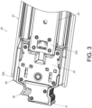
- the connecting member 28 comprises a cover body 34 (as shown in FIG. 3 ).
- the slide rail assembly 20 further comprises at least one locking member 36 and a driving member 38 (as shown in FIG. 4 ).
- the slide rail assembly 20 comprises two locking members 36 as shown in FIG. 4 , but one locking member 36 is enough to work normally.
- the locking member 36 is configured to interact with the blocking feature 32.
- the connecting member 28 is formed with a space S configured to accommodate the operating member 26, the locking member 36 and the driving member 38.
- the connecting member 28 is formed with a through hole 40 corresponding to the locking member 36, and the through hole 40 is communicated with the space S.
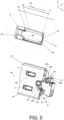
- the through hole 40 corresponds to the opening H of the first rail 22, and the locking member 36 can be extended into the opening H of the first rail 22 through the through hole 40 (as shown in FIG. 5 ) .
- the locking member 36 is configured to lock the second rail 24 relative to the first rail 22 at the predetermined position R.
- a locking section 41 of the locking member 36 in a locking state J1 is configured to interact with the blocking feature 32 of the first rail 22 for locking the second rail 24 (as shown in FIG. 5 ) .
- the locking section 41 of the locking member 36 and the blocking feature 32 of the first rail 22 are configured to block each other in order to lock the second rail 24 relative to the first rail 22 at the predetermined position R.
- the slide rail assembly 20 further comprises a first elastic member 42 (as shown in FIG. 5 ), and the operating member 26 is configured to be held at an initial position K1 in response to an elastic force of the first elastic member 42.
- the first elastic member 42 is a torsion spring, but the present invention is not limited thereto.
- the first elastic member 42 comprises a first elastic part 44a, a second elastic part 44b and a mounting part 46 connected between the first elastic part 44a and the second elastic part 44b.
- the mounting part 46 is mounted to a corresponding feature 48 of the connecting member 28 (such as a protruded section, but the present invention is not limited thereto) .
- the first elastic part 44a is configured to abut against a predetermined portion 49 of the first rail 22 (as shown in FIG. 5 ), and the second elastic part 44b is configured to provide an elastic force to the operating member 26 accordingly, such that the operating member 26 can be held at the initial position K1.
- the sliding rail assembly 20 further comprises a second elastic member 50 (as shown in FIG. 4 ), and the driving member 38 is configured to be held at a first driving position M1 in response to an elastic force of the second elastic member 50.
- the second elastic member 50 is a compression spring, but the present invention is not limited thereto.
- the slide rail assembly 20 further comprises a third elastic member 52 configured to provide an elastic force to the locking member 36 (as shown in FIG. 4 ), and the locking member 36 is configured to be held in the locking state J1 in response to the elastic force of the third elastic member 52 (as shown in FIG. 4 and FIG. 5 ) .
- the third elastic member 52 is a wire form spring, which is made of a specific material (such as a metal material), but the present invention is not limited thereto.
- the locking member 36 comprises a first wing part 54a, a second wing part 54b and a main body part 56 connected between the first wing part 54a and the second wing part 54b (as shown in FIG. 4 ).
- the main body part 56 corresponds to the through hole 40 of the connecting member 28.
- the first wing part 54a and the second wing part 54b are bent at a predetermined angle relative to the main body part 56.
- the main body part 56 of the locking member 36 has a first side and a second side opposite to each other.
- the third elastic member 52 is configured to apply an elastic force to the first side of the main body part 56 of the locking member 36 (as shown in FIG. 4 ) .
- the second side of the main body part 56 of the locking member 36 corresponds to the opening H of the first rail 22 (as shown in FIG. 5 ).
- the main body part 56 of the locking member 36 has the locking section 41 (as shown in FIG. 5 ).
- the operating member 26 is configured to drive the driving member 38 to linearly move to further drive the locking member 36 to move in order unlock the second rail 24 relative to the first rail 22 at the predetermined position R, such that the second rail 24 is able to move away from the predetermined position R relative to the first rail 22 along a first direction D1.
- the operating member 26 is configured to drive the driving member 38 to move (such as linearly move) relative to the second rail 24 from the first driving position M1 (as shown in FIG. 4 ) to a second driving position M2 (as shown in FIG. 6 ), such that the driving member 38 is configured to drive the locking member 36 to switch from the locking state J1 (as shown in FIG. 4 and FIG. 5 ) to an unlocking state J2 (as shown in FIG. 6 and FIG. 7 ).
- the locking section 41 of the locking member 36 and the blocking feature 32 of the first rail 22 no longer block each other (as shown in FIG. 7 ), so as to unlock the second rail 24 relative to the first rail 22 at the predetermined position R.
- one of the operating member 26 and the driving member 38 has a first structure 58
- the other one of the operating member 26 and the driving member 38 has a second structure 60 (as shown in FIG. 4 ).
- the first structure 58 and the second structure 60 can be a combination of two inclined surfaces, a combination of an inclined surface and a curved surface, or a combination of a curved surface and an inclined surface, but the present invention is not limited thereto.
- one of the driving member 38 and the locking member 36 has a first predetermined feature 62
- the other one of the driving member 38 and the locking member 36 has a second predetermined feature 64 (as shown in FIG. 4 ).
- the first predetermined feature 62 and the second predetermined feature 64 can be a combination of two inclined surfaces, a combination of an inclined surface and a curved surface, or a combination of a curved surface and an inclined surface, but the present invention is not limited thereto.
- the operating member 26 is configured to drive the driving member 38 to linearly move along a first predetermined direction A1 from the first driving position M1 (as shown in FIG. 4 ) to a second driving position M2 (as shown in FIG. 6 ) through contact between the first structure 58 and the second structure 60, such that the driving member 38 is configured to further drive the locking member 36 to transversely move (such as transversely displace or shift) along a second predetermined direction A2 (as shown in FIG.
- the locking section 41 of the main body part 56 of the locking member 36 and the blocking feature 32 of the first rail 22 no longer block each other (as shown in FIG. 7 , the locking section 41 of the locking member 36 and the blocking feature 32 of the first rail 22 are not aligned with each other) in order to unlock the second rail 24 relative to the first rail 22 at the predetermined position R, such that the second rail 24 is able to longitudinally move relative to the first rail 22 from the predetermined position R along the first direction D1.
- a linear moving direction of the driving member 38 is substantially identical to a moving direction of the second rail 24 relative to the first rail 22.
- the linear moving direction of the driving member 38 and the moving direction of the second rail 24 are identical to the longitudinal direction.
- an operating part 26a of the operating member 26 is extended out of the space S of the connecting member 28 (as shown in FIG. 4 ). Accordingly, the user can know that the second rail 24 is locked at the predetermined position R. In other words, the user can know that it is required to apply the force F to the operating part 26a of the operating member 26 in order to unlock the second rail 24 at the predetermined position R.
- the operating part 26a of the operating member 26 is located inside the space S of the connecting member 28 (as shown in FIG. 6 ). Accordingly, the user can know that the second rail 24 is unlocked at the predetermined position R.
- a moving direction of the operating member 26 is substantially perpendicular to the linear moving direction of the driving member 38 (as shown in FIG. 4 ).
- the moving direction of the operating member 26 is the vertical direction (or the height direction of the slide rail)
- the linear moving direction of the driving member 38 is the longitudinal direction (or the length direction of the slide rail).
- the moving direction of the operating member 26, the moving direction of the driving member 38 and the moving direction of the locking member 36 are substantially perpendicular to each other (as shown in FIG. 4 ).
- the moving direction the operating member 26 is the vertical direction (or the height direction of the slide rail)
- the linear moving direction of the driving member 38 is the longitudinal direction (or the length direction of the slide rail)
- the moving direction of the locking member 36 is the transverse direction (or the lateral direction of the slide rail).
- one of the connecting member 28 and the driving member 38 comprises a first limiting feature 66
- the other one of the connecting member 28 and the driving member 38 comprises a second limiting feature 68 (as shown in FIG. 4 ).
- the driving member 38 is configured to move relative to the connecting member 28 within a limited range through interaction between first limiting feature 66 and the second limiting feature 68.
- one of the first limiting feature 66 and the second limiting feature 68 is a protruded post
- the other one of the first limiting feature 66 and the second limiting feature 68 is an elongated hole (or slot). The protruded post passes through a portion of the elongated hole (or slot).
- the connecting member 28 further comprises at least one guiding feature, such as a first guiding feature 70a and a second guiding feature 70b, and a portion of the driving member 38 is configured to be supported between the first guiding feature 70a and the second guiding feature 70b (as shown in FIG. 4 , so as to improve stability of the driving member 38 when moving along a linear path (or longitudinal path).
- the first guiding feature 70a and the second guiding feature 70b are protrusions, but the present invention is not limited thereto.
- the second rail 24 is able to longitudinally move away from the predetermined position R relative to the first rail 22 along the first direction D1, such that the second rail 24 is able to be located at another predetermined position E (such as an extended position as shown in FIG. 8 ).
- the first elastic part 44a of the first elastic member 42 no longer abuts against the predetermined portion 49 of the first rail 22, such that the second elastic part 44b of the first elastic member 42 no longer provides the elastic force to the operating member 26, thus the operating member 26 stays at the non-initial position K2.
- the first elastic part 44a of the first elastic member 42 abuts against the predetermined portion 49 of the first rail 22 again, such that the second elastic part 44b of the first elastic member 42 is configured to provide the elastic force to the operating member 26 again, in order to drive the operating member 26 to return to the initial position K1 from the non-initial position K2 (as shown in FIG. 5 ).
- the slide rail assembly 20 according to the embodiments of the present invention has the following technical features:
Landscapes
- Seats For Vehicles (AREA)
- Drawers Of Furniture (AREA)
Abstract
Description
- The present invention is related to a slide rail assembly having a slide rail configured to be locked relative to another slide rail at a predetermined position.
- US patent number
US 10,342,341 B2 - US patent number
US 10,098,459 B2 - US patent publication number
US 2022/0160127 A1 discloses a slide rail assembly comprising at least two rails. When one of the rails is located at a retracted position relative to the other rail, a locking member is configured to be engaged with a blocking portion of the first rail in order to lock the two rails at the retracted position. - The rails of the slide rail assemblies in the aforementioned cases are configured to be locked at the retracted positions through the locking member (or engaging member). The locking member (or engaging members) is configured to work by rotation. However, for different market requirements, it is important to develop various products for the user.
- This in mind, the present invention aims at providing a slide rail assembly having a slide rail configured to be locked relative to another slide rail at a predetermined position.
- This is achieved by a slide rail assembly according to
claim 1 and claim 8. The dependent claims pertain to corresponding further developments and improvements. - As will be seen more clearly from the detailed description following below, the claimed slide rail assembly comprises a first rail, a second rail, a locking member, a driving member and an operating member. The second rail is movable relative to the first rail. The locking member is configured to lock the second rail relative to the first rail at a predetermined position. The driving member is movable relative to the second rail. When a force is applied to the operating member to move the operating member from an initial position to a non-initial position, the operating member is configured to drive the driving member to linearly move to further drive the locking member to move, in order to unlock the second rail relative to the first rail at the predetermined position.
- As will be seen more clearly from the detailed description following below, the claimed slide rail assembly comprises a first rail, a second rail, a connecting member, a locking member and an operating member. The second rail is longitudinally movable relative to the first rail. The connecting member is connected to the second rail. The locking member is configured to lock the second rail relative to the first rail at a retracted position. The connecting member is formed with a space configured to accommodate the operating member. When the operating member is moved from an initial position to a non-initial position, the operating member is configured to drive the locking member to transversely move to be switched from a locking state to an unlocking state, in order to unlock the second rail relative to the first rail at the retracted position.
- In the following, the invention is further illustrated by way of example, taking reference to the accompanying drawings thereof:
-
FIG. 1 is a diagram showing a slide rail assembly according to an embodiment of the present invention; -
FIG. 2 is an exploded view of the slide rail assembly according to an embodiment of the present invention; -
FIG. 3 is a partial view of the slide rail assembly comprising a cover body according to an embodiment of the present invention; -
FIG. 4 is a partial view of the slide rail assembly with removing the cover body in a first viewing angle according to an embodiment of the present invention; -
FIG. 5 is a partial view of the slide rail assembly in a second viewing angle according to an embodiment of the present invention; -
FIG. 6 is a partial view of the slide rail assembly with removing the cover body according to an embodiment of the present invention; -
FIG. 7 is a partial view of the slide rail assembly in the second viewing angle according to an embodiment of the present invention; and -
FIG. 8 is a diagram showing the slide rail assembly being in an extended state according to an embodiment of the present invention. - As shown in
FIG. 1 andFIG. 2 , aslide rail assembly 20 comprises afirst rail 22, asecond rail 24 and anoperating member 26 according to an embodiment of the present invention. Preferably, theslide rail assembly 20 further comprises a connectingmember 28. - The
second rail 24 is longitudinally movable relative to thefirst rail 22 and is located at a predetermined position R (such as a retracted position, but the present invention is not limited thereto). In the present embodiment, the X-axis is a longitudinal direction (or a length direction of the slide rail), the Y-axis is a transverse direction (or a lateral direction of the slide rail), and the Z-axis is a vertical direction (or a height direction of the slide rail). - Preferably, the
slide rail assembly 20 further comprises athird rail 30 and afourth rail 31 movably mounted between thefirst rail 22 and thesecond rail 24. Thethird rail 30 and thefourth rail 31 are configured to extend a traveling distance of thesecond rail 24 relative to thefirst rail 22. - Preferably, the
first rail 22 has afront part 22a. Thefourth rail 31 has arear part 31b. Thefirst rail 22 comprises at least oneblocking feature 32. In the present embodiment, thefirst rail 22 comprises twoblocking features 32 as shown inFIG. 2 , but oneblocking feature 32 is enough to work normally. In addition, theblocking feature 32 is arranged adjacent to thefront part 22a of thefirst rail 22. In the present embodiment, theblocking feature 32 is an inner wall of an opening H, but the present invention is not limited thereto. Or, in other embodiments, theblocking feature 32 can be an inner wall of a recessed part or a groove; or theblocking feature 32 can be a protrusion. The present invention is not limited thereto. - The connecting
member 28 is connected, such as fixedly connected, to thesecond rail 24. The connectingmember 28 can be seen as a portion of thesecond rail 24. Thesecond rail 24 has afront part 24a and arear part 24b. In the present embodiment, the connectingmember 28 is arranged adjacent to thefront part 24a of thesecond rail 24. - As shown in
FIG. 3 andFIG. 4 , the connectingmember 28 comprises a cover body 34 (as shown inFIG. 3 ). After removing thecover body 34, it can be seen that theslide rail assembly 20 further comprises at least onelocking member 36 and a driving member 38 (as shown inFIG. 4 ). In the present embodiment, theslide rail assembly 20 comprises twolocking members 36 as shown inFIG. 4 , but onelocking member 36 is enough to work normally. Thelocking member 36 is configured to interact with theblocking feature 32. - As shown in
FIG. 4 andFIG. 5 , the connectingmember 28 is formed with a space S configured to accommodate theoperating member 26, thelocking member 36 and thedriving member 38. - Preferably, the connecting
member 28 is formed with a throughhole 40 corresponding to thelocking member 36, and thethrough hole 40 is communicated with the space S. When thesecond rail 24 is located relative to thefirst rail 22 at the predetermined position R, the throughhole 40 corresponds to the opening H of thefirst rail 22, and thelocking member 36 can be extended into the opening H of thefirst rail 22 through the through hole 40 (as shown inFIG. 5 ) . When thesecond rail 24 is located relative to thefirst rail 22 at the predetermined position R, thelocking member 36 is configured to lock thesecond rail 24 relative to thefirst rail 22 at the predetermined position R. More particularly, alocking section 41 of thelocking member 36 in a locking state J1 is configured to interact with theblocking feature 32 of thefirst rail 22 for locking the second rail 24 (as shown inFIG. 5 ) . For example, thelocking section 41 of thelocking member 36 and theblocking feature 32 of thefirst rail 22 are configured to block each other in order to lock thesecond rail 24 relative to thefirst rail 22 at the predetermined position R. - Preferably, the
slide rail assembly 20 further comprises a first elastic member 42 (as shown inFIG. 5 ), and theoperating member 26 is configured to be held at an initial position K1 in response to an elastic force of the firstelastic member 42. In the present embodiment, the firstelastic member 42 is a torsion spring, but the present invention is not limited thereto. Furthermore, the firstelastic member 42 comprises a firstelastic part 44a, a secondelastic part 44b and a mountingpart 46 connected between the firstelastic part 44a and the secondelastic part 44b. The mountingpart 46 is mounted to acorresponding feature 48 of the connecting member 28 (such as a protruded section, but the present invention is not limited thereto) . The firstelastic part 44a is configured to abut against apredetermined portion 49 of the first rail 22 (as shown inFIG. 5 ), and the secondelastic part 44b is configured to provide an elastic force to the operatingmember 26 accordingly, such that the operatingmember 26 can be held at the initial position K1. - Preferably, the sliding
rail assembly 20 further comprises a second elastic member 50 (as shown inFIG. 4 ), and the drivingmember 38 is configured to be held at a first driving position M1 in response to an elastic force of the secondelastic member 50. In the present embodiment, the secondelastic member 50 is a compression spring, but the present invention is not limited thereto. - Preferably, the
slide rail assembly 20 further comprises a thirdelastic member 52 configured to provide an elastic force to the locking member 36 (as shown inFIG. 4 ), and the lockingmember 36 is configured to be held in the locking state J1 in response to the elastic force of the third elastic member 52 (as shown inFIG. 4 andFIG. 5 ) . In the present embodiment, the thirdelastic member 52 is a wire form spring, which is made of a specific material (such as a metal material), but the present invention is not limited thereto. - Preferably, the locking
member 36 comprises afirst wing part 54a, asecond wing part 54b and amain body part 56 connected between thefirst wing part 54a and thesecond wing part 54b (as shown inFIG. 4 ). Themain body part 56 corresponds to the throughhole 40 of the connectingmember 28. Thefirst wing part 54a and thesecond wing part 54b are bent at a predetermined angle relative to themain body part 56. When the lockingmember 36 is held in the locking state J1 by the elastic force of the thirdelastic member 52, thefirst wing part 54a and thesecond wing part 54b are configured to respectively abut against outer edge walls surrounding the through hole 40 (as shown inFIG. 4 ). - Preferably, the
main body part 56 of the lockingmember 36 has a first side and a second side opposite to each other. The thirdelastic member 52 is configured to apply an elastic force to the first side of themain body part 56 of the locking member 36 (as shown inFIG. 4 ) . When thesecond rail 24 is located relative to thefirst rail 22 at the predetermined position R, the second side of themain body part 56 of the lockingmember 36 corresponds to the opening H of the first rail 22 (as shown inFIG. 5 ). In addition, themain body part 56 of the lockingmember 36 has the locking section 41 (as shown inFIG. 5 ). - As shown in
FIG. 4 to FIG. 7 , when a user applies a force F to the operatingmember 26 to move the operatingmember 26 from the initial position K1 (as shown inFIG. 4 andFIG. 5 ) to a non-initial position K2 (as shown inFIG. 6 andFIG. 7 ), the operatingmember 26 is configured to drive the drivingmember 38 to linearly move to further drive the lockingmember 36 to move in order unlock thesecond rail 24 relative to thefirst rail 22 at the predetermined position R, such that thesecond rail 24 is able to move away from the predetermined position R relative to thefirst rail 22 along a first direction D1. - Furthermore, when the force F is applied to the operating
member 26 to move the operatingmember 26 from the initial position K1 to the non-initial position K2, the operatingmember 26 is configured to drive the drivingmember 38 to move (such as linearly move) relative to thesecond rail 24 from the first driving position M1 (as shown inFIG. 4 ) to a second driving position M2 (as shown inFIG. 6 ), such that the drivingmember 38 is configured to drive the lockingmember 36 to switch from the locking state J1 (as shown inFIG. 4 andFIG. 5 ) to an unlocking state J2 (as shown inFIG. 6 andFIG. 7 ). As such, the lockingsection 41 of the lockingmember 36 and the blockingfeature 32 of thefirst rail 22 no longer block each other (as shown inFIG. 7 ), so as to unlock thesecond rail 24 relative to thefirst rail 22 at the predetermined position R. - Preferably, one of the operating
member 26 and the drivingmember 38 has afirst structure 58, and the other one of the operatingmember 26 and the drivingmember 38 has a second structure 60 (as shown inFIG. 4 ). Thefirst structure 58 and thesecond structure 60 can be a combination of two inclined surfaces, a combination of an inclined surface and a curved surface, or a combination of a curved surface and an inclined surface, but the present invention is not limited thereto. - Preferably, one of the driving
member 38 and the lockingmember 36 has a firstpredetermined feature 62, and the other one of the drivingmember 38 and the lockingmember 36 has a second predetermined feature 64 (as shown inFIG. 4 ). The firstpredetermined feature 62 and the secondpredetermined feature 64 can be a combination of two inclined surfaces, a combination of an inclined surface and a curved surface, or a combination of a curved surface and an inclined surface, but the present invention is not limited thereto. - When the force F is applied to the operating
member 26 to move the operatingmember 26 from the initial position K1 (as shown inFIG. 4 andFIG. 5 ) to the non-initial position K2 (as shown inFIG. 6 andFIG. 7 ), the operatingmember 26 is configured to drive the drivingmember 38 to linearly move along a first predetermined direction A1 from the first driving position M1 (as shown inFIG. 4 ) to a second driving position M2 (as shown inFIG. 6 ) through contact between thefirst structure 58 and thesecond structure 60, such that the drivingmember 38 is configured to further drive the lockingmember 36 to transversely move (such as transversely displace or shift) along a second predetermined direction A2 (as shown inFIG. 4 ) to switch the lockingmember 36 from the locking state J1 (as shown inFIG. 4 andFIG. 5 ) to the unlocking state J2 (as shown inFIG. 6 andFIG. 7 ) through contact between the firstpredetermined feature 62 and the secondpredetermined feature 64. As such, the lockingsection 41 of themain body part 56 of the lockingmember 36 and the blockingfeature 32 of thefirst rail 22 no longer block each other (as shown inFIG. 7 , the lockingsection 41 of the lockingmember 36 and the blockingfeature 32 of thefirst rail 22 are not aligned with each other) in order to unlock thesecond rail 24 relative to thefirst rail 22 at the predetermined position R, such that thesecond rail 24 is able to longitudinally move relative to thefirst rail 22 from the predetermined position R along the first direction D1. - Preferably, a linear moving direction of the driving
member 38 is substantially identical to a moving direction of thesecond rail 24 relative to thefirst rail 22. For example, the linear moving direction of the drivingmember 38 and the moving direction of thesecond rail 24 are identical to the longitudinal direction. - Preferably, when the operating
member 26 is located at the initial position K1 in response to the elastic force of the firstelastic member 42, an operatingpart 26a of the operatingmember 26 is extended out of the space S of the connecting member 28 (as shown inFIG. 4 ). Accordingly, the user can know that thesecond rail 24 is locked at the predetermined position R. In other words, the user can know that it is required to apply the force F to theoperating part 26a of the operatingmember 26 in order to unlock thesecond rail 24 at the predetermined position R. - Preferably, when the operating
member 26 is located at the non-initial position K2, the operatingpart 26a of the operatingmember 26 is located inside the space S of the connecting member 28 (as shown inFIG. 6 ). Accordingly, the user can know that thesecond rail 24 is unlocked at the predetermined position R. - Preferably, a moving direction of the operating
member 26 is substantially perpendicular to the linear moving direction of the driving member 38 (as shown inFIG. 4 ). For example, the moving direction of the operatingmember 26 is the vertical direction (or the height direction of the slide rail), and the linear moving direction of the drivingmember 38 is the longitudinal direction (or the length direction of the slide rail). - Preferably, the moving direction of the operating
member 26, the moving direction of the drivingmember 38 and the moving direction of the lockingmember 36 are substantially perpendicular to each other (as shown inFIG. 4 ). For example, the moving direction the operatingmember 26 is the vertical direction (or the height direction of the slide rail), the linear moving direction of the drivingmember 38 is the longitudinal direction (or the length direction of the slide rail), and the moving direction of the lockingmember 36 is the transverse direction (or the lateral direction of the slide rail). - Preferably, one of the connecting
member 28 and the drivingmember 38 comprises a first limitingfeature 66, and the other one of the connectingmember 28 and the drivingmember 38 comprises a second limiting feature 68 (as shown inFIG. 4 ). The drivingmember 38 is configured to move relative to the connectingmember 28 within a limited range through interaction between first limitingfeature 66 and the second limitingfeature 68. In the present embodiment, one of the first limitingfeature 66 and the second limitingfeature 68 is a protruded post, and the other one of the first limitingfeature 66 and the second limitingfeature 68 is an elongated hole (or slot). The protruded post passes through a portion of the elongated hole (or slot). - Preferably, the connecting
member 28 further comprises at least one guiding feature, such as afirst guiding feature 70a and asecond guiding feature 70b, and a portion of the drivingmember 38 is configured to be supported between thefirst guiding feature 70a and thesecond guiding feature 70b (as shown inFIG. 4 , so as to improve stability of the drivingmember 38 when moving along a linear path (or longitudinal path). In the present embodiment, thefirst guiding feature 70a and thesecond guiding feature 70b are protrusions, but the present invention is not limited thereto. - As shown in
FIG. 7 andFIG. 8 , when the lockingmember 36 is disengaged from the blockingfeature 32 of the first rail 22 (as shown inFIG. 7 ), thesecond rail 24 is able to longitudinally move away from the predetermined position R relative to thefirst rail 22 along the first direction D1, such that thesecond rail 24 is able to be located at another predetermined position E (such as an extended position as shown inFIG. 8 ). - Moreover, when the
second rail 24 is located at the predetermined position E and when the user stops applying the force F to the operatingmember 26, the firstelastic part 44a of the firstelastic member 42 no longer abuts against thepredetermined portion 49 of thefirst rail 22, such that the secondelastic part 44b of the firstelastic member 42 no longer provides the elastic force to the operatingmember 26, thus the operatingmember 26 stays at the non-initial position K2. Furthermore, when thesecond rail 24 is longitudinally moved from the predetermined position E along a second direction D2 opposite to the first direction D1 to return to the predetermined position R, the firstelastic part 44a of the firstelastic member 42 abuts against thepredetermined portion 49 of thefirst rail 22 again, such that the secondelastic part 44b of the firstelastic member 42 is configured to provide the elastic force to the operatingmember 26 again, in order to drive the operatingmember 26 to return to the initial position K1 from the non-initial position K2 (as shown inFIG. 5 ). - Therefore, the
slide rail assembly 20 according to the embodiments of the present invention has the following technical features: - 1. Different from the locking member (or engaging member) of the prior art unlocking the second rail through rotation, the locking
member 36 of the present invention is configured to unlock thesecond rail 24 at the predetermined position without rotation. As such, in contrast to the prior art, the lockingmember 36 of the present invention has a greater moving range, especially a greater transverse movement moving range, such that the present invention is better to apply to slide rail assemblies with different thicknesses (such as transverse thickness). - 2. Since the locking
member 36 is not configured to work by rotation, impact-resistant structural strength of the lockingmember 36 is better than that of the prior art locking the second rail relative to the first rail through rotation. - 3. When the
second rail 24 is located relative to thefirst rail 22 at the predetermined position R and when the operatingmember 26 is located at the initial position K1 in response to the elastic force of the firstelastic member 42, the operatingpart 26a of the operatingmember 26 is extended out of the space S of the connecting member 28 (as shown inFIG. 4 ) . Accordingly, the user can know that thesecond rail 24 is locked at the predetermined position R.
Claims (15)
- A slide rail assembly (20), comprising:a first rail (22);a second rail (24) movable relative to the first rail (22);a locking member (36) configured to lock the second rail (24) relative to the first rail (22) at a predetermined position;a driving member (38) movable relative to the second rail (24); andan operating member (26);characterized in that:
wherein when a force is applied to the operating member (26) to move the operating member (26) from an initial position to a non-initial position, the operating member (26) is configured to drive the driving member (38) to linearly move to further drive the locking member (36) to move, in order to unlock the second rail (24) relative to the first rail (22) at the predetermined position. - The slide rail assembly of claim 1, characterized in that a linear moving direction of the driving member (38) is substantially identical to a moving direction of the second rail (24) relative to the first rail (22).
- The slide rail assembly of claim 1 or 2, further characterized by a connecting member (28) connected to the second rail (24), wherein the connecting member (28) is formed with a space configured to accommodate the operating member (26) ; wherein when the operating member (26) is located at the initial position, an operating part (26a) of the operating member (26) is extended out of the space of the connecting member (28); wherein when the operating member (26) is located at the non-initial position, the operating part (26a) of the operating member (26) is located inside the space of the connecting member (28).
- The slide rail assembly of claim 3, characterized in that the space of the connecting member (28) is further configured to accommodate the driving member (38) and the locking member (36) .
- The slide rail assembly of claim 2, characterized in that a moving direction of the operating member (26) is substantially perpendicular to the linear moving direction of the driving member (38) .
- The slide rail assembly of claim 3 or 4, further characterized by a first elastic member (42), wherein when the second rail (24) is locked relative to the first rail (22) at the predetermined position, the operating member (26) is configured to be held at the initial position in response to an elastic force of the first elastic member (42).
- The slide rail assembly of claim 6, further characterized by a second elastic member (50) and a third elastic member (52), wherein the driving member (38) is configured to be held at a first driving position in response to an elastic force of the second elastic member (50); wherein when the force is applied to the operating member (26) to move the operating member (26) from the initial position to the non-initial position, the operating member (26) is configured to drive the driving member (38) to linearly move from the first driving position to a second driving position to further drive the locking member (36) to switch from a locking state to an unlocking state, in order to unlock the second rail (24) relative to the first rail (22) at the predetermined position; wherein the third elastic member (52) is configured to provide an elastic force to the locking member (36).
- A slide rail assembly (20), comprising:a first rail (22);a second rail (24) longitudinally movable relative to the first rail (22);a connecting member (28) connected to the second rail (24);a locking member (36) configured to lock the second rail (24) relative to the first rail (22) at a retracted position; andan operating member (26);characterized in that:wherein the connecting member (28) is formed with a space configured to accommodate the operating member (26);wherein when the operating member (26) is moved from an initial
position to a non-initial position, the operating member (26) is configured to drive the locking member (36) to transversely move to be switched from a locking state to an unlocking state, in order to unlock the second rail (24) relative to the first rail (22) at the retracted position. - The slide rail assembly of claim 8, further characterized by a driving member (38) movable relative to the second rail (24); wherein the operating member (26) is configured to drive the locking member (36) to transversely move to be switched from the locking state to the unlocking state through linear movement of the driving member (38); wherein a linear moving direction of the driving member (38) is substantially identical to a moving direction of the second rail (24) relative to the first rail (22).
- The slide rail assembly of claim 9, characterized in that moving directions of the operating member (26), the driving member (38) and the locking member (36) are substantially perpendicular to each other.
- The slide rail assembly of claim 9 or 10, characterized in that when the operating member (26) is located at the initial position, an operating part (26a) of the operating member (26) is extended out of the space of the connecting member (28) ; wherein when the operating member (26) is located at the non-initial position, the operating part (26a) of the operating member (26) is located inside the space of the connecting member (28).
- The slide rail assembly of claim 11, characterized in that the space of the connecting member (28) is further configured to accommodate the driving member (38) and the locking member (36).
- The slide rail assembly of claim 11 or 12, further characterized by a first elastic member (42), wherein the operating member (26) is configured to be held at the initial position in response to an elastic force of the first elastic member (42).
- The slide rail assembly of claim 13, further characterized by a second elastic member (50), wherein the driving member (38) is configured to be held at a first driving position in response to an elastic force of the second elastic member (50); wherein when a force is applied to the operating member (26) to move the operating member (26) from the initial position to the non-initial position, the operating member (26) is configured to drive the driving member (38) to linearly move from the first driving position to a second driving position to further drive the locking member (36) to switch from the locking state to the unlocking state, in order to unlock the second rail (24) relative to the first rail (22) at the predetermined position.
- The slide rail assembly of claim 14, further characterized by a third elastic member (52) configured to provide an elastic force to the locking member (36).
Applications Claiming Priority (1)
| Application Number | Priority Date | Filing Date | Title |
|---|---|---|---|
| TW111148130A TWI861632B (en) | 2022-12-13 | 2022-12-13 | Slide rail assembly |
Publications (2)
| Publication Number | Publication Date |
|---|---|
| EP4386161A1 true EP4386161A1 (en) | 2024-06-19 |
| EP4386161B1 EP4386161B1 (en) | 2025-06-25 |
Family
ID=86609821
Family Applications (1)
| Application Number | Title | Priority Date | Filing Date |
|---|---|---|---|
| EP23176008.3A Active EP4386161B1 (en) | 2022-12-13 | 2023-05-30 | Slide rail assembly |
Country Status (4)
| Country | Link |
|---|---|
| US (1) | US12426706B2 (en) |
| EP (1) | EP4386161B1 (en) |
| JP (1) | JP7666792B2 (en) |
| TW (1) | TWI861632B (en) |
Families Citing this family (5)
| Publication number | Priority date | Publication date | Assignee | Title |
|---|---|---|---|---|
| TWI847902B (en) * | 2023-10-30 | 2024-07-01 | 川湖科技股份有限公司 | Slide rail assembly |
| TWI847910B (en) * | 2023-11-09 | 2024-07-01 | 川湖科技股份有限公司 | Slide rail assembly |
| USD1058357S1 (en) * | 2024-06-18 | 2025-01-21 | Changzhou Joshua Home Furnishing Co., Ltd. | Plastic guide rail |
| TWI897515B (en) * | 2024-07-03 | 2025-09-11 | 南俊國際股份有限公司 | Slide rail assembly |
| TWI907254B (en) * | 2025-01-20 | 2025-12-01 | 南俊國際股份有限公司 | Locking device and its slide rail assembly and the operation method of the slide rail assembly |
Citations (7)
| Publication number | Priority date | Publication date | Assignee | Title |
|---|---|---|---|---|
| US20040056572A1 (en) * | 2002-09-25 | 2004-03-25 | King Slide Works Co., Ltd. | Latch assembly for a track device |
| US20070241651A1 (en) * | 2006-04-17 | 2007-10-18 | Burgess Thomas E Iii | Drawer slide with releasable latch |
| US20110176755A1 (en) * | 2010-01-19 | 2011-07-21 | Martas Precision Slide Co., Ltd. | Interlocking device for slide rail |
| US20170156498A1 (en) * | 2015-12-03 | 2017-06-08 | King Slide Works Co., Ltd. | Slide rail assembly and locking device thereof |
| US10342341B2 (en) | 2017-04-12 | 2019-07-09 | King Slide Works Co., Ltd. | Slide rail assembly |
| US10376054B1 (en) * | 2018-04-02 | 2019-08-13 | King Slide Works Co., Ltd. | Slide rail assembly and rack system |
| US20220160127A1 (en) | 2020-11-24 | 2022-05-26 | King Slide Works Co., Ltd. | Slide rail assembly |
Family Cites Families (14)
| Publication number | Priority date | Publication date | Assignee | Title |
|---|---|---|---|---|
| US7571968B2 (en) * | 2006-11-09 | 2009-08-11 | Central Industrial Supply Company | Front release lock with disconnect lock for a drawer slide |
| US8528998B2 (en) * | 2010-05-25 | 2013-09-10 | Accuride International, Inc. | Adjustable detent retention system and method |
| US8317278B2 (en) * | 2010-08-18 | 2012-11-27 | Knape & Vogt Manufacturing Company | Releasably locking slide assemblies |
| US8540328B2 (en) * | 2011-01-05 | 2013-09-24 | King Slide Works Co., Ltd. | Control mechanism for drawer slide assembly |
| US8282176B1 (en) * | 2011-06-10 | 2012-10-09 | King Slide Works Co., Ltd. | Slide assembly having locking mechanism |
| US8876230B2 (en) * | 2011-09-24 | 2014-11-04 | Hardware Resources, Inc. | Durable drawer retainer apparatus and method of use |
| CN104244662B (en) * | 2013-06-18 | 2018-09-21 | 伊顿制造(格拉斯哥)有限合伙莫尔日分支机构 | Slide track component and slide track component pair |
| TWI616167B (en) * | 2017-04-12 | 2018-03-01 | 川湖科技股份有限公司 | Slide rail assembly |
| TWI616166B (en) * | 2017-04-12 | 2018-03-01 | 川湖科技股份有限公司 | Slide rail assembly |
| CN108720377B (en) * | 2017-04-19 | 2019-08-27 | 川湖科技股份有限公司 | Sliding rail assembly |
| TWI642385B (en) * | 2017-08-31 | 2018-12-01 | 川湖科技股份有限公司 | Slide rail assembly and slide rail mechanism thereof |
| TWI646923B (en) * | 2017-11-27 | 2019-01-11 | 川湖科技股份有限公司 | Slide rail assembly and rail assembly |
| US10736422B2 (en) * | 2018-10-04 | 2020-08-11 | King Slide Works Co., Ltd. | Slide rail assembly |
| TWI700056B (en) * | 2019-06-12 | 2020-08-01 | 川湖科技股份有限公司 | Slide rail assembly |
-
2022
- 2022-12-13 TW TW111148130A patent/TWI861632B/en active
-
2023
- 2023-04-27 US US18/308,034 patent/US12426706B2/en active Active
- 2023-05-30 EP EP23176008.3A patent/EP4386161B1/en active Active
- 2023-08-01 JP JP2023125267A patent/JP7666792B2/en active Active
Patent Citations (8)
| Publication number | Priority date | Publication date | Assignee | Title |
|---|---|---|---|---|
| US20040056572A1 (en) * | 2002-09-25 | 2004-03-25 | King Slide Works Co., Ltd. | Latch assembly for a track device |
| US20070241651A1 (en) * | 2006-04-17 | 2007-10-18 | Burgess Thomas E Iii | Drawer slide with releasable latch |
| US20110176755A1 (en) * | 2010-01-19 | 2011-07-21 | Martas Precision Slide Co., Ltd. | Interlocking device for slide rail |
| US20170156498A1 (en) * | 2015-12-03 | 2017-06-08 | King Slide Works Co., Ltd. | Slide rail assembly and locking device thereof |
| US10098459B2 (en) | 2015-12-03 | 2018-10-16 | King Slide Works Co., Ltd. | Slide rail assembly and locking device thereof |
| US10342341B2 (en) | 2017-04-12 | 2019-07-09 | King Slide Works Co., Ltd. | Slide rail assembly |
| US10376054B1 (en) * | 2018-04-02 | 2019-08-13 | King Slide Works Co., Ltd. | Slide rail assembly and rack system |
| US20220160127A1 (en) | 2020-11-24 | 2022-05-26 | King Slide Works Co., Ltd. | Slide rail assembly |
Also Published As
| Publication number | Publication date |
|---|---|
| TW202423343A (en) | 2024-06-16 |
| US12426706B2 (en) | 2025-09-30 |
| EP4386161B1 (en) | 2025-06-25 |
| JP7666792B2 (en) | 2025-04-22 |
| US20240188716A1 (en) | 2024-06-13 |
| TWI861632B (en) | 2024-11-11 |
| JP2024084678A (en) | 2024-06-25 |
Similar Documents
| Publication | Publication Date | Title |
|---|---|---|
| US12426706B2 (en) | Slide rail assembly | |
| EP3322269A1 (en) | Bracket device and slide rail assembly comprising the same | |
| EP4035568B1 (en) | Slide rail assembly | |
| EP3387950B1 (en) | Slide rail assembly | |
| US7028370B2 (en) | Retracting apparatus, drawer apparatus and sliding door apparatus | |
| US8522639B2 (en) | Steering apparatus | |
| EP4018883A1 (en) | Slide rail assembly | |
| EP4028616B1 (en) | Hub assembly for door handle | |
| EP3231325B1 (en) | Bracket device | |
| EP3387952A1 (en) | Slide rail assembly | |
| US20120261937A1 (en) | Push button mechanism for opening and closing a storage compartment for a vehicle | |
| EP3886546A1 (en) | Slide rail assembly | |
| EP3833169B1 (en) | Slide rail assembly | |
| EP3957210B1 (en) | Slide rail assembly | |
| CN204804526U (en) | door fixing device | |
| EP3440961B1 (en) | Slide rail assembly and rail kit thereof | |
| JP2018044426A (en) | Slide rail assembly and its rail kit | |
| CN112092589A (en) | Structure for providing separation strength of relatively sliding door | |
| EP4570126A1 (en) | Slide rail assembly | |
| CN112983153B (en) | Locking structure for linear middle guide rail of split sliding door | |
| JP7683156B2 (en) | Interlock Kits and Related Furniture Assemblies | |
| EP2894281A1 (en) | Affixation device for vehicle door | |
| CN112523626B (en) | Locking structure for linear central rail of opposed sliding door | |
| JP4027900B2 (en) | Truck assembly for motor vehicle seats and seat with such a truck assembly | |
| CN118208488A (en) | Slide rail assembly |
Legal Events
| Date | Code | Title | Description |
|---|---|---|---|
| PUAI | Public reference made under article 153(3) epc to a published international application that has entered the european phase |
Free format text: ORIGINAL CODE: 0009012 |
|
| STAA | Information on the status of an ep patent application or granted ep patent |
Free format text: STATUS: REQUEST FOR EXAMINATION WAS MADE |
|
| 17P | Request for examination filed |
Effective date: 20240227 |
|
| AK | Designated contracting states |
Kind code of ref document: A1 Designated state(s): AL AT BE BG CH CY CZ DE DK EE ES FI FR GB GR HR HU IE IS IT LI LT LU LV MC ME MK MT NL NO PL PT RO RS SE SI SK SM TR |
|
| GRAP | Despatch of communication of intention to grant a patent |
Free format text: ORIGINAL CODE: EPIDOSNIGR1 |
|
| STAA | Information on the status of an ep patent application or granted ep patent |
Free format text: STATUS: GRANT OF PATENT IS INTENDED |
|
| GRAJ | Information related to disapproval of communication of intention to grant by the applicant or resumption of examination proceedings by the epo deleted |
Free format text: ORIGINAL CODE: EPIDOSDIGR1 |
|
| STAA | Information on the status of an ep patent application or granted ep patent |
Free format text: STATUS: REQUEST FOR EXAMINATION WAS MADE |
|
| GRAP | Despatch of communication of intention to grant a patent |
Free format text: ORIGINAL CODE: EPIDOSNIGR1 |
|
| STAA | Information on the status of an ep patent application or granted ep patent |
Free format text: STATUS: GRANT OF PATENT IS INTENDED |
|
| INTG | Intention to grant announced |
Effective date: 20250314 |
|
| RAP3 | Party data changed (applicant data changed or rights of an application transferred) |
Owner name: KING SLIDE TECHNOLOGY CO., LTD. Owner name: KING SLIDE WORKS CO., LTD. |
|
| GRAS | Grant fee paid |
Free format text: ORIGINAL CODE: EPIDOSNIGR3 |
|
| GRAA | (expected) grant |
Free format text: ORIGINAL CODE: 0009210 |
|
| STAA | Information on the status of an ep patent application or granted ep patent |
Free format text: STATUS: THE PATENT HAS BEEN GRANTED |
|
| AK | Designated contracting states |
Kind code of ref document: B1 Designated state(s): AL AT BE BG CH CY CZ DE DK EE ES FI FR GB GR HR HU IE IS IT LI LT LU LV MC ME MK MT NL NO PL PT RO RS SE SI SK SM TR |
|
| REG | Reference to a national code |
Ref country code: GB Ref legal event code: FG4D |
|
| REG | Reference to a national code |
Ref country code: CH Ref legal event code: EP |
|
| REG | Reference to a national code |
Ref country code: DE Ref legal event code: R096 Ref document number: 602023004227 Country of ref document: DE |
|
| REG | Reference to a national code |
Ref country code: CH Ref legal event code: EP |
|
| REG | Reference to a national code |
Ref country code: IE Ref legal event code: FG4D |
|
| PG25 | Lapsed in a contracting state [announced via postgrant information from national office to epo] |
Ref country code: FI Free format text: LAPSE BECAUSE OF FAILURE TO SUBMIT A TRANSLATION OF THE DESCRIPTION OR TO PAY THE FEE WITHIN THE PRESCRIBED TIME-LIMIT Effective date: 20250625 |
|
| REG | Reference to a national code |
Ref country code: LT Ref legal event code: MG9D |
|
| PG25 | Lapsed in a contracting state [announced via postgrant information from national office to epo] |
Ref country code: GR Free format text: LAPSE BECAUSE OF FAILURE TO SUBMIT A TRANSLATION OF THE DESCRIPTION OR TO PAY THE FEE WITHIN THE PRESCRIBED TIME-LIMIT Effective date: 20250926 Ref country code: NO Free format text: LAPSE BECAUSE OF FAILURE TO SUBMIT A TRANSLATION OF THE DESCRIPTION OR TO PAY THE FEE WITHIN THE PRESCRIBED TIME-LIMIT Effective date: 20250925 |
|
| PG25 | Lapsed in a contracting state [announced via postgrant information from national office to epo] |
Ref country code: BG Free format text: LAPSE BECAUSE OF FAILURE TO SUBMIT A TRANSLATION OF THE DESCRIPTION OR TO PAY THE FEE WITHIN THE PRESCRIBED TIME-LIMIT Effective date: 20250625 |
|
| PG25 | Lapsed in a contracting state [announced via postgrant information from national office to epo] |
Ref country code: HR Free format text: LAPSE BECAUSE OF FAILURE TO SUBMIT A TRANSLATION OF THE DESCRIPTION OR TO PAY THE FEE WITHIN THE PRESCRIBED TIME-LIMIT Effective date: 20250625 |
|
| PG25 | Lapsed in a contracting state [announced via postgrant information from national office to epo] |
Ref country code: RS Free format text: LAPSE BECAUSE OF FAILURE TO SUBMIT A TRANSLATION OF THE DESCRIPTION OR TO PAY THE FEE WITHIN THE PRESCRIBED TIME-LIMIT Effective date: 20250925 |
|
| PG25 | Lapsed in a contracting state [announced via postgrant information from national office to epo] |
Ref country code: LV Free format text: LAPSE BECAUSE OF FAILURE TO SUBMIT A TRANSLATION OF THE DESCRIPTION OR TO PAY THE FEE WITHIN THE PRESCRIBED TIME-LIMIT Effective date: 20250625 |
|
| REG | Reference to a national code |
Ref country code: NL Ref legal event code: MP Effective date: 20250625 |
|
| PG25 | Lapsed in a contracting state [announced via postgrant information from national office to epo] |
Ref country code: NL Free format text: LAPSE BECAUSE OF FAILURE TO SUBMIT A TRANSLATION OF THE DESCRIPTION OR TO PAY THE FEE WITHIN THE PRESCRIBED TIME-LIMIT Effective date: 20250625 |
|
| PG25 | Lapsed in a contracting state [announced via postgrant information from national office to epo] |
Ref country code: PT Free format text: LAPSE BECAUSE OF FAILURE TO SUBMIT A TRANSLATION OF THE DESCRIPTION OR TO PAY THE FEE WITHIN THE PRESCRIBED TIME-LIMIT Effective date: 20251027 |
|
| REG | Reference to a national code |
Ref country code: AT Ref legal event code: MK05 Ref document number: 1806587 Country of ref document: AT Kind code of ref document: T Effective date: 20250625 |
|
| PG25 | Lapsed in a contracting state [announced via postgrant information from national office to epo] |
Ref country code: IS Free format text: LAPSE BECAUSE OF FAILURE TO SUBMIT A TRANSLATION OF THE DESCRIPTION OR TO PAY THE FEE WITHIN THE PRESCRIBED TIME-LIMIT Effective date: 20251025 |
|
| PG25 | Lapsed in a contracting state [announced via postgrant information from national office to epo] |
Ref country code: AT Free format text: LAPSE BECAUSE OF FAILURE TO SUBMIT A TRANSLATION OF THE DESCRIPTION OR TO PAY THE FEE WITHIN THE PRESCRIBED TIME-LIMIT Effective date: 20250625 Ref country code: SM Free format text: LAPSE BECAUSE OF FAILURE TO SUBMIT A TRANSLATION OF THE DESCRIPTION OR TO PAY THE FEE WITHIN THE PRESCRIBED TIME-LIMIT Effective date: 20250625 |
|
| PG25 | Lapsed in a contracting state [announced via postgrant information from national office to epo] |
Ref country code: CZ Free format text: LAPSE BECAUSE OF FAILURE TO SUBMIT A TRANSLATION OF THE DESCRIPTION OR TO PAY THE FEE WITHIN THE PRESCRIBED TIME-LIMIT Effective date: 20250625 |
|
| PG25 | Lapsed in a contracting state [announced via postgrant information from national office to epo] |
Ref country code: PL Free format text: LAPSE BECAUSE OF FAILURE TO SUBMIT A TRANSLATION OF THE DESCRIPTION OR TO PAY THE FEE WITHIN THE PRESCRIBED TIME-LIMIT Effective date: 20250625 |
|
| PG25 | Lapsed in a contracting state [announced via postgrant information from national office to epo] |
Ref country code: EE Free format text: LAPSE BECAUSE OF FAILURE TO SUBMIT A TRANSLATION OF THE DESCRIPTION OR TO PAY THE FEE WITHIN THE PRESCRIBED TIME-LIMIT Effective date: 20250625 |
|
| PG25 | Lapsed in a contracting state [announced via postgrant information from national office to epo] |
Ref country code: SK Free format text: LAPSE BECAUSE OF FAILURE TO SUBMIT A TRANSLATION OF THE DESCRIPTION OR TO PAY THE FEE WITHIN THE PRESCRIBED TIME-LIMIT Effective date: 20250625 |
|
| PG25 | Lapsed in a contracting state [announced via postgrant information from national office to epo] |
Ref country code: ES Free format text: LAPSE BECAUSE OF FAILURE TO SUBMIT A TRANSLATION OF THE DESCRIPTION OR TO PAY THE FEE WITHIN THE PRESCRIBED TIME-LIMIT Effective date: 20250625 |
|
| PG25 | Lapsed in a contracting state [announced via postgrant information from national office to epo] |
Ref country code: DK Free format text: LAPSE BECAUSE OF FAILURE TO SUBMIT A TRANSLATION OF THE DESCRIPTION OR TO PAY THE FEE WITHIN THE PRESCRIBED TIME-LIMIT Effective date: 20250625 |
|
| PGFP | Annual fee paid to national office [announced via postgrant information from national office to epo] |
Ref country code: IE Payment date: 20260330 Year of fee payment: 4 |
|
| PG25 | Lapsed in a contracting state [announced via postgrant information from national office to epo] |
Ref country code: IT Free format text: LAPSE BECAUSE OF FAILURE TO SUBMIT A TRANSLATION OF THE DESCRIPTION OR TO PAY THE FEE WITHIN THE PRESCRIBED TIME-LIMIT Effective date: 20250625 |
|
| PLBE | No opposition filed within time limit |
Free format text: ORIGINAL CODE: 0009261 |
|
| STAA | Information on the status of an ep patent application or granted ep patent |
Free format text: STATUS: NO OPPOSITION FILED WITHIN TIME LIMIT |
|
| REG | Reference to a national code |
Ref country code: CH Ref legal event code: L10 Free format text: ST27 STATUS EVENT CODE: U-0-0-L10-L00 (AS PROVIDED BY THE NATIONAL OFFICE) Effective date: 20260507 |