EP4386145A1 - Trajectory generation system - Google Patents
Trajectory generation system Download PDFInfo
- Publication number
- EP4386145A1 EP4386145A1 EP22875381.0A EP22875381A EP4386145A1 EP 4386145 A1 EP4386145 A1 EP 4386145A1 EP 22875381 A EP22875381 A EP 22875381A EP 4386145 A1 EP4386145 A1 EP 4386145A1
- Authority
- EP
- European Patent Office
- Prior art keywords
- omission
- target trajectory
- target
- trajectory
- specific portion
- Prior art date
- Legal status (The legal status is an assumption and is not a legal conclusion. Google has not performed a legal analysis and makes no representation as to the accuracy of the status listed.)
- Granted
Links
Images



Classifications
-
- E—FIXED CONSTRUCTIONS
- E02—HYDRAULIC ENGINEERING; FOUNDATIONS; SOIL SHIFTING
- E02F—DREDGING; SOIL-SHIFTING
- E02F9/00—Component parts of dredgers or soil-shifting machines, not restricted to one of the kinds covered by groups E02F3/00 - E02F7/00
- E02F9/20—Drives; Control devices
-
- E—FIXED CONSTRUCTIONS
- E02—HYDRAULIC ENGINEERING; FOUNDATIONS; SOIL SHIFTING
- E02F—DREDGING; SOIL-SHIFTING
- E02F3/00—Dredgers; Soil-shifting machines
- E02F3/04—Dredgers; Soil-shifting machines mechanically-driven
- E02F3/28—Dredgers; Soil-shifting machines mechanically-driven with digging tools mounted on a dipper- or bucket-arm, i.e. there is either one arm or a pair of arms, e.g. dippers, buckets
- E02F3/36—Component parts
- E02F3/42—Drives for dippers, buckets, dipper-arms or bucket-arms
- E02F3/43—Control of dipper or bucket position; Control of sequence of drive operations
- E02F3/435—Control of dipper or bucket position; Control of sequence of drive operations for dipper-arms, backhoes or the like
- E02F3/437—Control of dipper or bucket position; Control of sequence of drive operations for dipper-arms, backhoes or the like providing automatic sequences of movements, e.g. linear excavation, keeping dipper angle constant
-
- E—FIXED CONSTRUCTIONS
- E02—HYDRAULIC ENGINEERING; FOUNDATIONS; SOIL SHIFTING
- E02F—DREDGING; SOIL-SHIFTING
- E02F3/00—Dredgers; Soil-shifting machines
- E02F3/04—Dredgers; Soil-shifting machines mechanically-driven
- E02F3/28—Dredgers; Soil-shifting machines mechanically-driven with digging tools mounted on a dipper- or bucket-arm, i.e. there is either one arm or a pair of arms, e.g. dippers, buckets
- E02F3/36—Component parts
- E02F3/42—Drives for dippers, buckets, dipper-arms or bucket-arms
- E02F3/43—Control of dipper or bucket position; Control of sequence of drive operations
- E02F3/435—Control of dipper or bucket position; Control of sequence of drive operations for dipper-arms, backhoes or the like
- E02F3/438—Memorising movements for repetition, e.g. play-back capability
-
- E—FIXED CONSTRUCTIONS
- E02—HYDRAULIC ENGINEERING; FOUNDATIONS; SOIL SHIFTING
- E02F—DREDGING; SOIL-SHIFTING
- E02F9/00—Component parts of dredgers or soil-shifting machines, not restricted to one of the kinds covered by groups E02F3/00 - E02F7/00
- E02F9/26—Indicating devices
- E02F9/261—Surveying the work-site to be treated
- E02F9/262—Surveying the work-site to be treated with follow-up actions to control the work tool, e.g. controller
-
- E—FIXED CONSTRUCTIONS
- E02—HYDRAULIC ENGINEERING; FOUNDATIONS; SOIL SHIFTING
- E02F—DREDGING; SOIL-SHIFTING
- E02F9/00—Component parts of dredgers or soil-shifting machines, not restricted to one of the kinds covered by groups E02F3/00 - E02F7/00
- E02F9/26—Indicating devices
- E02F9/264—Sensors and their calibration for indicating the position of the work tool
- E02F9/265—Sensors and their calibration for indicating the position of the work tool with follow-up actions (e.g. control signals sent to actuate the work tool)
Definitions
- the present invention relates to a trajectory generating system that generates a target trajectory of an attachment of a work machine.
- Patent Literature 1 discloses a technique that corrects a target point (soil release position in Patent Literature 1) of an attachment of a work machine.
- Patent Literature 1 JP 2000-64359 A
- Patent Literature 1 discloses that a position of one target point among a series of operations of the attachment is corrected. Patent Literature 1, however, does not disclose how a series of operations of the attachment is performed at points other than the target point in a case where the target point is corrected. Therefore, the movement of the attachment after the correction of the target point might give a feeling of anxiety to a worker around the work machine.
- An object of the present invention is to provide a trajectory generating system that can prevent a movement of an attachment from giving a feeling of anxiety to a worker around a work machine in a case where a target trajectory of the attachment is corrected.
- the present invention provides a trajectory generating system that is used in a work machine including a machine body and an attachment.
- the attachment is mounted on the machine body.
- the trajectory generating system generates a trajectory of a specific portion of the attachment.
- the trajectory generating system includes a target trajectory setting unit and a target trajectory correcting unit.
- the target trajectory setting unit sets a target trajectory including a target path including a plurality of target points and time information that is information about a time for a movement of the specific portion along the target points.
- the target trajectory correcting unit corrects the target trajectory.
- the target trajectory correcting unit specifies at least one omission point among the plurality of target points according to a predetermined condition, and sets two points adjacent to both sides of the omission point as an omission start point and an omission end point, respectively.
- the target trajectory correcting unit sets a corrected target path that is a path from the omission start point to the omission end point so that the omission point for the specific portion is omitted from the plurality of target points on the target trajectory.
- the target trajectory correcting unit sets the time information about the specific portion from the omission start point to the omission end point in the corrected target path based on at least one of a movement distance and a movement time of the specific portion from the omission start point to the omission end point on a pre-correction target trajectory.
- FIG. 1 is a side view of a work machine 10 or the like to which the trajectory generating system 1 according to the present embodiment is applied.
- FIG. 2 is a block diagram of the trajectory generating system 1 according to the present embodiment.
- FIG. 3 is a diagram illustrating a target trajectory TR of a specific portion 15e of an attachment 15 illustrated in FIG. 1 .
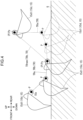
- FIG. 4 is a diagram illustrating the target trajectory TR in a case where a bucket 15d1 illustrated in FIG. 3 performs excavation.
- FIG. 5 is a top view of the work machine 10 illustrated in FIG. 1 , and is a diagram illustrating the target trajectory TR of the specific portion 15e during slewing of an upper slewing body 13.
- the trajectory generating system 1 is a system that generates a target trajectory TR (see FIG. 3 ) of a specific portion 15e of an attachment 15 of a work machine 10 illustrated in FIG. 1 .
- the trajectory generating system 1 includes an attitude sensor 21, a situation detection unit 23 (see FIG. 2 ), a communication device 25, a mobile terminal 30, and a controller 40. Note that the trajectory generating system 1 may include the work machine 10.
- the work machine 10 is a machine that performs work, for example, a construction machine such as an excavator that performs construction work.
- the work machine 10 is configured to be automatically driven by the controller 40.
- the work machine 10 includes a machine body 10a, the attachment 15, an actuator 17, and a drive control unit 19 (see FIG. 2 ).
- the machine body 10a is a main portion of the work machine 10.
- the machine body 10a includes a lower travelling body 11 and an upper slewing body 13.
- the lower travelling body 11 causes the work machine 10 to travel.
- the lower travelling body 11 includes, for example, a crawler.
- the upper slewing body 13 is mounted on the lower travelling body 11 so as to be able to slew about a slewing center shaft extending in an up-down direction.
- the attachment 15 is a portion for performing work, and is attached to the machine body 10a (more specifically, the upper slewing body 13).
- the attachment 15 includes a boom 15b, an arm 15c, and a distal end attachment 15d.
- the boom 15b is mounted on the upper slewing body 13 so as to be raised and lowered (rotatable up and down).
- the arm 15c is rotatably mounted on the boom 15b.
- the distal end attachment 15d is provided at a distal end of the attachment 15 and is rotatably attached to the arm 15c.
- the distal end attachment 15d may be, for example, a bucket 15d1 that excavates (scoops) soil, a device (a grapple or the like) that pinches an object, or a device (a breaker or the like) that crushes or excavates an object.
- a specific portion of the attachment 15 is defined as the specific portion 15e.
- the specific portion 15e is a portion that is moved along the target trajectory TR (see FIG. 3 ).
- the specific portion 15e is a distal end portion of the distal end attachment 15d (more specifically, the bucket 15d1) in the example illustrated in FIGS. 1 , 3 , and 5 , and is a proximal end portion of the bucket 15d1 (a connection portion between the arm 15c and the distal end attachment 15d illustrated in FIG. 1 ) in the example illustrated in FIG. 4 .
- the actuator 17 moves the work machine 10.
- the actuator 17 includes a slewing motor 17a, a boom cylinder 17b, an arm cylinder 17c, and a distal end attachment cylinder 17d.
- the slewing motor 17a slews the upper slewing body 13 with respect to the lower travelling body 11.
- the slewing motor 17a may be a hydraulic motor or an electric motor.
- the boom cylinder 17b raises and lowers the boom 15b with respect to the upper slewing body 13.
- the boom cylinder 17b is, for example, a hydraulic telescopic cylinder (hydraulic cylinder). The same applies to the arm cylinder 17c and the distal end attachment cylinder 17d.
- the arm cylinder 17c rotates the arm 15c with respect to the boom 15b.
- the distal end attachment cylinder 17d rotates the distal end attachment 15d with respect to the arm 15c.
- a cylinder or a motor for driving the distal end attachment 15d may be provided.
- the drive control unit 19 controls the actuator 17.
- the drive control unit 19 may include a hydraulic circuit or an electric circuit.
- the attitude sensor 21 detects an attitude of the work machine 10.
- the attitude sensor 21 may include a sensor (for example, a rotary encoder) that detects an angle, a sensor that detects an inclination with respect to a horizontal plane, or a sensor that detects a stroke of a hydraulic cylinder that drives the attachment 15.
- the attitude sensor 21 may detect the attitude of the work machine 10 based on at least one of a two-dimensional image and a distance image. In this case, the two-dimensional image or the distance image may be captured by an imaging device 23b (see FIG. 2 , described later).
- the attitude sensor 21 may be mounted on the work machine 10 or may be disposed outside the work machine 10 (for example, at a work site) (the same also applies to the situation detection unit 23, the communication device 25, and the controller 40).
- the attitude sensor 21 includes a slewing angle sensor 21a, a boom angle sensor 21b, an arm angle sensor 21c, a distal end attachment angle sensor 21d, and a reference position sensor 21e.
- the slewing angle sensor 21a detects a slewing angle of the upper slewing body 13 with respect to the lower travelling body 11.
- the boom angle sensor 21b detects a rotation angle of the boom 15b with respect to the upper slewing body 13.
- the arm angle sensor 21c detects a rotation angle of the arm 15c with respect to the boom 15b.
- the distal end attachment angle sensor 21d detects a rotation angle of the distal end attachment 15d with respect to the arm 15c.
- the reference position sensor 21e detects the position and orientation of the work machine 10 with respect to the work site.
- the reference position sensor 21e may perform detection with a positioning system.
- the positioning system may be a satellite positioning system, such as, a global navigation satellite system (GNSS).
- GNSS global navigation satellite system
- the reference position sensor 21e may include a GNSS antenna 21e1 and the like.
- the positioning system may use a total station.
- the situation detection unit 23 detects a situation (information) of the work machine 10 (bucket 15d1).
- the situation detection unit 23 may detect a situation (machine condition, work condition, etc.) of the work machine 10 itself or may detect a situation around the work machine 10.
- the situation detection unit 23 includes a load detection unit 23a and an imaging device 23b.
- the load detection unit 23a detects a load acting on the work machine 10 illustrated in FIG. 1 .
- the load detection unit 23a (see FIG. 2 ) may detect a load acting on the attachment 15.
- the load detection unit 23a may detect a load acting on the actuator 17.
- the load detection unit 23a may detect the load acting on the attachment 15 by detecting the load acting on the actuator 17.
- the load detection unit 23a may detect a load acting on the distal end attachment 15d (for example, the bucket 15d1).
- the load detection unit 23a may detect a load (for example, an oil pressure) acting on the distal end attachment cylinder 17d (for example, the bucket cylinder).
- the imaging device 23b (see FIG. 2 ) images an imaging object.
- the "imaging object” may be the work machine 10 or an object around the work machine 10.
- the imaging device 23b may detect two-dimensional information about an imaging object (for example, a position or a shape).
- the imaging device 23b may detect three-dimensional information about an imaging object or may acquire an image (distance image) having distance information (depth information).
- the imaging device 23b may detect three-dimensional information about an imaging object based on the distance image and the two-dimensional image.
- the imaging device 23b may include a camera (monocular camera) that detects two-dimensional information.
- the imaging device 23b may include a device that detects three-dimensional information with laser light, and may include, for example, a light detection and ranging (LIDAR), or, for example, a time of flight (TOF) sensor.
- the imaging device 23b may include a device (for example, a millimeter wave radar) that detects three-dimensional information using radio waves.
- the imaging device 23b may include a stereo camera. Specifically, for example, the imaging device 23b may detect the soil volume in the bucket 15d1 in a case where the distal end attachment 15d is the bucket 15d1.
- the communication device 25 performs communication.
- the communication device 25 may perform communication between the controller 40 and the mobile terminal 30.
- the communication device 25 may perform communication between the controllers 40 disposed outside and inside the work machine 10.
- Communication by the communication device 25 may include at least one of wireless communication, wired communication, and optical communication.
- the mobile terminal 30 is a device (computer) used by a worker.
- the mobile terminal 30 may be, for example, a tablet or a smartphone.
- the mobile terminal 30 includes an operation unit 31 and a display unit 33.
- the operation unit 31 is operated by a worker. For example, in the operation unit 31, an operation for performing a setting related to an automatic operation of the work machine 10 (see FIG. 1 ) may be performed. In the operation unit 31, an operation for instructing setting or correction of the target trajectory TR (see FIG. 3 , described later) may be performed.
- the display unit 33 performs display.
- the display unit 33 displays information about the target trajectory TR (see FIG. 3 ).
- the display unit 33 performs display related to a post-correction target trajectory TRb (see FIG. 3 ) (described later).
- the device provided with the display unit 33 for example, the mobile terminal 30
- the device provided with the operation unit 31 may be integrated or separated.
- the controller 40 is a computer that inputs and outputs signals, performs arithmetic (processing), stores information, and the like.
- the function of the controller 40 is implemented by causing an arithmetic unit to execute a program stored in a storage unit of the controller 40.
- the controller 40 acquires information about the attitude of the work machine 10 (see FIG. 1 ) detected by the attitude sensor 21.
- the controller 40 causes the drive control unit 19 to automatically operate the work machine 10.
- the controller 40 sets and corrects the target trajectory TR (see FIG. 3 ).
- the controller 40 may be provided separately from the mobile terminal 30 or may be provided in the mobile terminal 30.
- the controller 40 includes a target trajectory setting unit 41, a target trajectory correcting unit 43, and an operation control unit 45.
- the target trajectory setting unit 41 sets the target trajectory TR illustrated in FIG. 3 .
- the target trajectory TR is corrected as necessary, and the target trajectory setting unit 41 (see FIG. 2 ) sets a pre-correction target trajectory TRa that is a pre-correction target trajectory TR.
- the target trajectory TR is trajectory to be a target for the specific portion 15e. More specifically, an order set of the plurality of target points P (for example, three-dimensional coordinates) of the specific portion 15e of the attachment 15 is referred to as a "target path". In the example illustrated in FIG. 3 , each position and order from the target point P1 to the target point P12 correspond to the target path.
- the target path to which a time parameter is added is referred to as the target trajectory TR.
- This "time parameter” is, specifically for example, a movement time ("a point-to-point time") of the specific portion 15e between the two target points P in consecutive order.
- the time parameter is information (time information or time-of-day information) about the time for a movement of the specific portion 15e along the target points P.
- the target trajectory setting unit 41 may set the pre-correction target trajectory TRa based on teaching, or may set the pre-correction target trajectory TRa based on a method other than teaching (for example, input of coordinates by the operation unit 31 (see FIG. 2 )).
- the "teaching" is performed as follows. A worker (operator) gets aboard the work machine 10 illustrated in FIG. 1 to operate the work machine 10, or the worker remotely operates the work machine 10. Then, the worker operates the work machine 10 to move the specific portion 15e at such a speed that a time parameter desired to be set as the target trajectory TR is set along the target path desired to be set as the target trajectory TR illustrated in FIG. 3 .
- the target trajectory setting unit 41 (see FIG. 2 ) then sets the trajectory along which the specific portion 15e has moved, as the pre-correction target trajectory TRa.
- the pre-correction target trajectory TRa including the target path and the time information is stored in the controller 40.
- the target trajectory correcting unit 43 (see FIG. 2 ) corrects the pre-correction target trajectory TRa.
- the target trajectory correcting unit 43 sets the post-correction target trajectory TRb obtained by omitting some of the target points P on the pre-correction target trajectory TRa (details will be described later).
- the operation control unit 45 automatically operates the work machine 10 (see FIG. 1 ).
- the operation control unit 45 controls the work machine 10 so that the specific portion 15e of the attachment 15 moves along the target trajectory TR. More specifically, the operation control unit 45 (see FIG. 2 ) controls the work machine 10 (see FIG. 1 ) so that the specific portion 15e moves in accordance with the target path (coordinates and order of each target point P) set as the target trajectory TR and the time parameter (for example, a movement time between the target points P.
- the operation control unit 45 controls the operation (attitude) of the work machine 10 by inputting a command signal to the drive control unit 19 (see FIG. 2 ).
- the target trajectory correcting unit 43 illustrated in FIG. 2 may correct the target trajectory TR (see FIG. 3 ) based on a determination of the controller 40 (automatically). For example, the target trajectory correcting unit 43 may correct the target trajectory TR based on a detection result of the situation detection unit 23, the detection result being input to the controller 40. More specifically, the target trajectory correcting unit 43 may correct the target trajectory TR (see FIG. 3 ) based on at least one of the situation of the work machine 10 (see FIG. 1 ) itself and the situation around the work machine 10 (a specific example will be described later). The target trajectory correcting unit 43 may correct the target trajectory TR when a command (input) of a unit other than the controller 40 is present. For example, the target trajectory correcting unit 43 may correct the target trajectory TR in accordance with a manual operation of the operation unit 31 (for example, tablet operation or the like) by a worker.
- a manual operation of the operation unit 31 for example, tablet operation or the like
- the outline of the correction of the target trajectory TR (more specifically, the pre-correction target trajectory TRa) illustrated in FIG. 3 by the target trajectory correcting unit 43 is as follows.
- the target trajectory correcting unit 43 will be described with reference to FIGS. 2 and 3 .
- the target trajectory correcting unit 43 sets the target path of the post-correction target trajectory TRb, the target path being obtained by omitting some of the plurality of target points P on the pre-correction target trajectory TRa illustrated in FIG. 3 .
- the target trajectory correcting unit 43 determines the time parameter of the post-correction target trajectory TRb based on the information about the pre-correction target trajectory TRa (in consideration of the pre-correction target trajectory TRa). Details of the correction of the target trajectory TR by the target trajectory correcting unit 43 are as follows.
- the target trajectory correcting unit 43 sets two points (two different points) of the plurality of target points P on the pre-correction target trajectory TRa as an omission start point Ps and an omission end point Pe.
- the order of the omission end point Pe is later than the order of the omission start point Ps.
- the target trajectory correcting unit 43 sets the post-correction target trajectory TRb formed by omitting target points P (the target points P5 to P10 in the example illustrated in FIG. 3 ) between the omission start point Ps and the omission end point Pe from the plurality of target points P on the pre-correction target trajectory TRa. Note that how to determine the omission start point Ps and the omission end point Pe will be described later.
- the target trajectory correcting unit 43 sets the post-correction target trajectory TRb so that a worker feels the speeds identical to each other when the specific portion 15e moves along the pre-correction target trajectory TRa and when the specific portion 15e moves along the post-correction target trajectory TRb.
- a feeling of anxiety uncomfortable feeling
- an abrupt movement of the attachment 15 can be prevented.
- the target trajectory correcting unit 43 sets the post-correction target trajectory TRb from the omission start point Ps to the omission end point Pe based on at least one of a movement distance and a movement time of the specific portion 15e from the omission start point Ps to the omission end point Pe on the pre-correction target trajectory TRa. More specifically, the target trajectory correcting unit 43 sets the post-correction target trajectory TRb (hereinafter, also referred to as post-omission target trajectory TRnew) from the omission start point Ps to the omission end point Pe as in the following setting examples 1 and 2.
- the target trajectory correcting unit 43 may set the post-omission target trajectory TRnew (post-correction target trajectory TRb) so that the movement times of the specific portion 15e from the omission start point Ps to the omission end point Pe become equal to each other before and after correction.
- the target trajectory correcting unit 43 sets the post-omission target trajectory TRnew so that a post-correction movement time Tnew described below becomes equal to a pre-correction movement time T.
- the post-correction movement time Tnew is a movement time of the specific portion 15e from the omission start point Ps to the omission end point Pe on the post-correction target trajectory TRb (that is, on the post-omission target trajectory TRnew).
- the pre-correction movement time T is a movement time of the specific portion 15e from the omission start point Ps to the omission end point Pe on the pre-correction target trajectory TRa.
- the pre-correction movement time T and the post-correction movement time Tnew are equal to each other, the speeds felt by a worker when the specific portion 15e moves from the omission start point Ps to the omission end point Pe are equivalent to each other before and after correction. Therefore, a feeling of anxiety can be prevented from being given to a worker who views the specific portion 15e that moves along the post-correction target trajectory TRb.
- the target point P4 is the omission start point Ps
- the target point P11 is the omission end point Pe.
- the pre-correction movement time T is assumed to be 7 seconds.
- the target trajectory correcting unit 43 sets the post-omission target trajectory TRnew so that the post-correction movement time Tnew becomes 7 seconds.
- the target trajectory correcting unit 43 may set the post-omission target trajectory TRnew so that average speeds of the specific portion 15e (average values of movement speeds) from the omission start point Ps to the omission end point Pe become equal to each other before and after correction.
- the target trajectory correcting unit 43 sets the post-omission target trajectory TRnew so that a post-correction average speed Vnew described below becomes equal to a pre-correction average speed V.
- the pre-correction average speed V is an average speed of the specific portion 15e from the omission start point Ps to the omission end point Pe on the pre-correction target trajectory TRa.
- the post-correction average speed Vnew is an average speed of the specific portion 15e from the omission start point Ps to the omission end point Pe on the post-correction target trajectory TRb (that is, on the post-omission target trajectory TRnew).
- the pre-correction average speed V and the post-correction average speed Vnew are equal to each other, the speeds felt by a worker when the specific portion 15e moves from the omission start point Ps to the omission end point Pe are equivalent to each other before and after correction. Therefore, a feeling of anxiety can be prevented from being given to a worker who views the specific portion 15e that moves along the post-correction target trajectory TRb.
- the time during which the specific portion 15e moves from the omission start point Ps to the omission end point Pe is shorter after correction than before correction. Therefore, the attachment 15 can be efficiently moved, and the work efficiency by the attachment 15 is improved.
- the pre-correction movement time T is assumed to be 7 seconds.
- a movement distance along the target path from the target point P4 to the target point P11 on the pre-correction target trajectory TRa is defined as L (L4 + L5 +...+ L9 + L10 illustrated in FIG. 3 ).
- T 7 seconds
- V L/7.
- a movement distance (linear distance) from the target point P4 to the target point P11 (that is, the post-omission target trajectory TRnew) on the post-correction target trajectory TRb is defined as Lnew.
- the post-correction target trajectory TRb can variously be set by the target trajectory correcting unit 43.
- the target trajectory correcting unit 43 may set the post-correction target trajectory TRb based on both the pre-correction movement time T and the pre-correction average speed V.
- the target trajectory correcting unit 43 may set the post-correction target trajectory TRb based on a value obtained by performing at least one of addition, subtraction, multiplication, and division of a correction value with respect to the pre-correction movement time T and the pre-correction average speed V.
- the target trajectory correcting unit 43 sets the omission start point Ps and the omission end point Pe as follows, for example.
- some of the target points P on the pre-correction target trajectory TRa during the operation for excavating soil (excavation operation) by the bucket 15d1 may be omitted.
- the target trajectory correcting unit 43 may set a position of the specific portion 15e at a time when the soil volume in the bucket 15d1 exceeds a predetermined soil volume threshold (condition A), as the omission start point Ps.
- the target trajectory correcting unit 43 may set a position of the specific portion 15e at a time when a load acting on the bucket 15d1 exceeds a predetermined load threshold (condition B), as the omission start point Ps.
- the excavation operation may be useless.
- the soil volume in the bucket 15d1 and the load acting on the bucket 15d1 are detected by the situation detection unit 23 described above (see FIG. 2 ).
- the situation detection unit 23 may detect only one of the soil volume in the bucket 15d1 and the load acting on the bucket 15d1.
- the specific portion 15e is a proximal end portion of the bucket 15d1.
- the target trajectory correcting unit 43 sets an end point of the excavation operation by the bucket 15d1 as the omission end point Pe.
- This excavation operation includes an operation such that the bucket 15d1 rotates toward the upper slewing body 13 (excavation side) with respect to the arm 15c (see FIG. 1 ) while the distal end portion of the bucket 15d1 moves into the ground (lower side with respect to the ground surface G) and toward the upper slewing body 13 (see FIG. 1 ).
- this excavation operation may include an operation such that the bucket 15d1 that has excavated soil moves (lifts) above the ground surface G at an attitude (angle) where soil can be held.
- the end point of such a series of the excavation operations of the bucket 15d 1 is set as the omission end point Pe.
- the next operation after the end of the excavation operation by the bucket 15d1 is, for example, an operation (lifting and slewing) including slewing of the upper slewing body 13 (see FIG. 1 ).
- an operation lifting and slewing
- a point before the end point of a series of the excavation operations of the bucket 15d1 may be set as the omission end point Pe.
- the target trajectory correcting unit 43 may set at least one of the omission start point Ps and the omission end point Pe based on the situation around the work machine 10 (see FIG. 1 ), the situation being detected by the situation detection unit 23 (see FIG. 2 ). Specific examples in this case are as follows.
- some of the target points P on the pre-correction target trajectory TRa at a time when the upper slewing body 13 slews (slewing operation) with respect to the lower travelling body 11 may be omitted.
- the target trajectory correcting unit 43 omits the path of the pre-correction target trajectory TRa, and sets the post-correction target trajectory TRb so that the specific portion 15e passes through the path shorter than that before correction (so as not to detour).
- the target trajectory correcting unit 43 sets the omission start point Ps and the omission end point Pe as follows.
- the attachment 15 enters an entry prohibition area when the specific portion 15e moves along the pre-correction target trajectory TRa.
- the target trajectory correcting unit 43 sets the omission start point Ps and the omission end point Pe so that the attachment 15 does not enter the entry prohibition area.
- the "entry prohibition area" is, for example, an area where an obstacle (topography, a vehicle such as a dump car, or the like) exists.
- the target trajectory correcting unit 43 may set at least any one of the omission start point Ps and the omission end point Pe based on information specified by the operation unit 31 (see FIG. 2 ). More specifically, a worker specifies the target point P desired to be set as the omission start point Ps from the target points P on the pre-correction target trajectory TRa using the operation unit 31. The target trajectory correcting unit 43 may set the target point P specified by the operation unit 31 as the omission start point Ps. The same applies to the omission end point Pe. Further, in another embodiment, a worker may specify target points P (in FIG.
- the display unit 33 displays information about the post-correction target trajectory TRb set by the target trajectory correcting unit 43. Specifically for example, the display unit 33 may display a figure representing the post-correction target trajectory TRb (for example, see FIGS. 3 to 5 ). The display unit 33 may display a moving image showing how the attachment 15 including the specific portion 15e moves along the post-correction target trajectory TRb.
- the trajectory generating system 1 is used in the work machine 10 having the machine body 10a and the attachment 15, and includes the target trajectory setting unit 41 (see FIG. 2 ) and the target trajectory correcting unit 43 (see FIG. 2 ).
- the attachment 15 is mounted on the machine body 10a and performs work.
- the target trajectory setting unit 41 sets the pre-correction target trajectory TRa (see FIG. 3 ) that is a target trajectory for the specific portion 15e of the attachment 15.
- the target trajectory TR includes a target path including a plurality of target points P and time information that is information about a time for a movement of the specific portion 15e along the plurality of target points P.
- the target trajectory correcting unit 43 corrects the pre-correction target trajectory TRa (see FIG. 3 ).
- the target trajectory correcting unit 43 sets two of the plurality of target points P on the pre-correction target trajectory TRa illustrated in FIG. 3 , as the omission start point Ps and the omission end point Pe.
- the target trajectory correcting unit 43 specifies at least one omission point among the plurality of target points P according to a predetermined condition, and sets two points adjacent to both sides of the omission point as the omission start point Ps and the omission end point Pe, respectively.
- the target trajectory correcting unit 43 (see FIG. 2 ) sets two of the plurality of target points P on the pre-correction target trajectory TRa illustrated in FIG. 3 , as the omission start point Ps and the omission end point Pe.
- the target trajectory correcting unit 43 sets the corrected target path that is the path from the omission start point Ps to the omission end point Pe so that the omission points for the specific portion 15e are omitted from the plurality of target points P on the pre-correction target trajectory TRa.
- the target trajectory correcting unit 43 sets the time parameter (time information) of the specific portion 15e from the omission start point Ps to the omission end point Pe on the post-correction target trajectory TRb based on at least any one of the movement distance and the movement time of the specific portion 15e from the omission start point Ps to the omission end point Pe on the pre-correction target trajectory TRa.
- the above configuration can provide the following effects.
- the post-correction target trajectory TRb (post-omission target trajectory TRnew) from the omission start point Ps to the omission end point Pe is set in consideration of at least one of the movement distance and the movement time of the specific portion 15e from the omission start point Ps to the omission end point Pe on the pre-correction target trajectory TRa. Therefore, the following effects can be obtained as compared with a case where neither the movement distance nor the movement time of the specific portion 15e from the omission start point Ps to the omission end point Pe on the pre-correction target trajectory TRa is considered.
- the post-correction target trajectory TRb can be set so that the movement of the specific portion 15e moving along the post-correction target trajectory TRb is close to the movement of the specific portion 15e moving along the pre-correction target trajectory TRa. Therefore, the post-correction target trajectory TRb can be set so that the speeds felt by a worker during the movement of the specific portion 15e from the omission start point Ps to the omission end point Pe become equivalent to each other before and after correction of the target trajectory TR. As a result, the trajectory generating system 1 (see FIG. 1 ) can prevent the movement of the attachment 15 from giving a feeling of anxiety to a worker around the work machine 10 in a case where the target trajectory TR of the attachment 15 is corrected.
- the target trajectory correcting unit 43 sets the post-correction target trajectory TRb (particularly, the time parameter) illustrated in FIG. 3 so that the following post-correction movement time Tnew becomes equal to the pre-correction movement time T.
- the post-correction movement time Tnew is a movement time of the specific portion 15e (on the post-omission target trajectory TRnew) from the omission start point Ps to the omission end point Pe on the post-correction target trajectory TRb (corrected target path).
- the pre-correction movement time T is a movement time of the specific portion 15e from the omission start point Ps to the omission end point Pe on the pre-correction target trajectory TRa.
- the trajectory generating system 1 illustrated in FIG. 1 can prevent a sense of anxiety from being given to a worker around the work machine 10.
- the target trajectory correcting unit 43 sets the post-correction target trajectory TRb illustrated in FIG. 3 so that the post-correction average speed Vnew described below becomes equal to the pre-correction average speed V.
- the post-correction average speed Vnew is an average speed of the specific portion 15e from the omission start point Ps to the omission end point Pe on the post-correction target trajectory TRb (on the post-omission target trajectory TRnew).
- the pre-correction average speed V is an average speed of the specific portion 15e from the omission start point Ps to the omission end point Pe on the pre-correction target trajectory TRa.
- the speeds felt by a worker during the movement of the specific portion 15e from the omission start point Ps to the omission end point Pe can be made equivalent to each other before and after correction of the target trajectory TR. Therefore, the trajectory generating system 1 illustrated in FIG. 1 can prevent a sense of anxiety from being given to a worker around the work machine 10. Further, in this case, the movement time of the specific portion 15e from the omission start point Ps to the omission end point Pe illustrated in FIG. 3 can be made shorter on the post-correction target trajectory TRb than on the pre-correction target trajectory TRa. Therefore, since the specific portion 15e (the attachment 15) can be efficiently moved, the work efficiency by the attachment 15 can be improved.
- the work machine 10 includes the bucket 15d1 illustrated in FIG. 4 , and the trajectory generating system 1 (see FIG. 1 ) includes the situation detection unit 23 (bucket information detection unit) (see FIG. 2 ).
- the bucket 15d1 constitutes the attachment 15 and excavates soil.
- the situation detection unit 23 detects the situation (information) of the bucket 15d1.
- the target trajectory correcting unit 43 sets the position of the specific portion 15e at a time when at least one of the following [Condition A] and [Condition B] is satisfied, as the omission start point Ps.
- [Condition A] The situation detection unit 23 (see FIG. 2 ) detects that the soil volume in the bucket 15d1 exceeds a predetermined soil volume threshold.
- [Condition B] The situation detection unit 23 (see FIG. 2 ) detects that the load acting on the bucket 15d1 exceeds a predetermined load threshold.
- the target trajectory correcting unit 43 may set the omission point based on the position of the specific portion 15e at a time when at least one of [condition A] and [condition B] is satisfied.
- the bucket 15d1 can be prevented from excavating soil excessively.
- the above configuration includes that the situation detection unit 23 detects only one of the soil volume in the bucket 15d1 and the load acting on the bucket 15d1, and the target trajectory correcting unit 43 determines only one of [Condition A] and [Condition B].
- the trajectory generating system 1 includes the display unit 33 that displays the information about the post-correction target trajectory TRb (see FIG. 3 ) set by the target trajectory correcting unit 43.
- a worker can be notified of the information about the post-correction target trajectory TRb by causing the display unit 33 (see FIG. 2 ) to display the information without actually moving the specific portion 15e along the post-correction target trajectory TRb illustrated in FIG. 3 .
- the connection of the components illustrated in FIG. 2 or the like may be changed.
- values such as the thresholds for example, the soil volume threshold and the load threshold
- the number of components may be changed, and some of the components do not have to be provided.
- the components may be fixed or connected directly or indirectly.
- a plurality of components and parts different from each other may be described as one component and part.
- what has been described as one component and part may be divided and provided as a plurality of different components and parts.
- the components each may have only some of features (function, arrangement, shape, operation, and the like).
- the present invention provides a trajectory generating system that is used in a work machine including a machine body and an attachment that is attached to the machine body and performs work, and generates a trajectory of a specific portion of the attachment.
- the trajectory generating system includes a target trajectory setting unit that sets a target trajectory including a target path including a plurality of target points and time information that is information about a time for a movement of the specific portion along the target points, and a target trajectory correcting unit that corrects the target trajectory.
- the target trajectory correcting unit specifies at least one omission point from the plurality of target points according to a predetermined condition, and sets two points adjacent to both sides of the omission point as an omission start point and an omission end point, respectively, and sets a corrected target path that is a path from the omission start point to the omission end point so that the omission point for the specific portion is omitted from the plurality of target points on the target trajectory.
- the target trajectory correcting unit sets the time information about the specific portion from the omission start point to the omission end point in the corrected target path based on at least one of a movement distance and a movement time of the specific portion from the omission start point to the omission end point on a pre-correction target trajectory.
- the target trajectory correcting unit may set the time information on the post-correction target trajectory so that a movement time of the specific portion from the omission start point to the omission end point in the corrected target path is equal to a movement time of the specific portion from the omission start point to the omission end point on the pre-correction target trajectory.
- the target trajectory correcting unit may set the post-correction target trajectory so that an average speed of the specific portion from the omission start point to the omission end point in the corrected target path is equal to an average speed of the specific portion from the omission start point to the omission end point on the pre-correction target trajectory.
- the work machine includes a bucket for excavation of soil as the attachment and further includes a bucket information detection unit that detects information about the bucket, and the target trajectory correcting unit sets the omission point based on a position of the specific portion at a time when at least one of a condition that the bucket information detection unit detects that a soil volume in the bucket exceeds a predetermined soil volume threshold and a condition that the bucket information detection unit detects that a load acting on the bucket exceeds a predetermined load threshold is satisfied.
- the above configuration may further include a display unit that displays at least one of the corrected target path and the time information set by the target trajectory correcting unit.
- the above configuration may further include a work machine including a machine body and an attachment that is attached to the machine body and performs work.
Landscapes
- Engineering & Computer Science (AREA)
- Mining & Mineral Resources (AREA)
- Mechanical Engineering (AREA)
- Civil Engineering (AREA)
- General Engineering & Computer Science (AREA)
- Structural Engineering (AREA)
- Life Sciences & Earth Sciences (AREA)
- General Life Sciences & Earth Sciences (AREA)
- Paleontology (AREA)
- Operation Control Of Excavators (AREA)
Abstract
Description
- The present invention relates to a trajectory generating system that generates a target trajectory of an attachment of a work machine.
- For example,
Patent Literature 1 discloses a technique that corrects a target point (soil release position in Patent Literature 1) of an attachment of a work machine. - Patent Literature 1:
JP 2000-64359 A -
Patent Literature 1 discloses that a position of one target point among a series of operations of the attachment is corrected.Patent Literature 1, however, does not disclose how a series of operations of the attachment is performed at points other than the target point in a case where the target point is corrected. Therefore, the movement of the attachment after the correction of the target point might give a feeling of anxiety to a worker around the work machine. - An object of the present invention is to provide a trajectory generating system that can prevent a movement of an attachment from giving a feeling of anxiety to a worker around a work machine in a case where a target trajectory of the attachment is corrected.
- The present invention provides a trajectory generating system that is used in a work machine including a machine body and an attachment. The attachment is mounted on the machine body. The trajectory generating system generates a trajectory of a specific portion of the attachment. The trajectory generating system includes a target trajectory setting unit and a target trajectory correcting unit. The target trajectory setting unit sets a target trajectory including a target path including a plurality of target points and time information that is information about a time for a movement of the specific portion along the target points. The target trajectory correcting unit corrects the target trajectory. The target trajectory correcting unit specifies at least one omission point among the plurality of target points according to a predetermined condition, and sets two points adjacent to both sides of the omission point as an omission start point and an omission end point, respectively. The target trajectory correcting unit sets a corrected target path that is a path from the omission start point to the omission end point so that the omission point for the specific portion is omitted from the plurality of target points on the target trajectory. The target trajectory correcting unit sets the time information about the specific portion from the omission start point to the omission end point in the corrected target path based on at least one of a movement distance and a movement time of the specific portion from the omission start point to the omission end point on a pre-correction target trajectory.
-
-
FIG. 1 is a side view of a work machine or the like to which a trajectory generating system according to one embodiment of the present invention is applied. -
FIG. 2 is a block diagram of the trajectory generating system according to one embodiment of the present invention. -
FIG. 3 is a diagram illustrating a target trajectory of a specific portion of an attachment illustrated inFIG. 1 . -
FIG. 4 is a diagram illustrating a target trajectory in a case where a bucket illustrated inFIG. 3 performs excavation. -
FIG. 5 is a top view of the work machine illustrated inFIG. 1 , and is a diagram illustrating a target trajectory of the specific portion during slewing of an upper slewing body. - A trajectory generating
system 1 according to one embodiment of the present invention will be described with reference toFIGS. 1 to 5 .FIG. 1 is a side view of awork machine 10 or the like to which thetrajectory generating system 1 according to the present embodiment is applied.FIG. 2 is a block diagram of thetrajectory generating system 1 according to the present embodiment.FIG. 3 is a diagram illustrating a target trajectory TR of aspecific portion 15e of anattachment 15 illustrated inFIG. 1 .FIG. 4 is a diagram illustrating the target trajectory TR in a case where a bucket 15d1 illustrated inFIG. 3 performs excavation.FIG. 5 is a top view of thework machine 10 illustrated inFIG. 1 , and is a diagram illustrating the target trajectory TR of thespecific portion 15e during slewing of anupper slewing body 13. - The
trajectory generating system 1 is a system that generates a target trajectory TR (seeFIG. 3 ) of aspecific portion 15e of anattachment 15 of awork machine 10 illustrated inFIG. 1 . Thetrajectory generating system 1 includes anattitude sensor 21, a situation detection unit 23 (seeFIG. 2 ), acommunication device 25, amobile terminal 30, and acontroller 40. Note that thetrajectory generating system 1 may include thework machine 10. - The
work machine 10 is a machine that performs work, for example, a construction machine such as an excavator that performs construction work. Thework machine 10 is configured to be automatically driven by thecontroller 40. Thework machine 10 includes amachine body 10a, theattachment 15, anactuator 17, and a drive control unit 19 (seeFIG. 2 ). - The
machine body 10a is a main portion of thework machine 10. Themachine body 10a includes alower travelling body 11 and anupper slewing body 13. Thelower travelling body 11 causes thework machine 10 to travel. The lowertravelling body 11 includes, for example, a crawler. Theupper slewing body 13 is mounted on thelower travelling body 11 so as to be able to slew about a slewing center shaft extending in an up-down direction. - The
attachment 15 is a portion for performing work, and is attached to themachine body 10a (more specifically, the upper slewing body 13). Theattachment 15 includes aboom 15b, anarm 15c, and adistal end attachment 15d. Theboom 15b is mounted on theupper slewing body 13 so as to be raised and lowered (rotatable up and down). Thearm 15c is rotatably mounted on theboom 15b. Thedistal end attachment 15d is provided at a distal end of theattachment 15 and is rotatably attached to thearm 15c. Thedistal end attachment 15d may be, for example, a bucket 15d1 that excavates (scoops) soil, a device (a grapple or the like) that pinches an object, or a device (a breaker or the like) that crushes or excavates an object. A specific portion of theattachment 15 is defined as thespecific portion 15e. Thespecific portion 15e is a portion that is moved along the target trajectory TR (seeFIG. 3 ). Thespecific portion 15e is a distal end portion of thedistal end attachment 15d (more specifically, the bucket 15d1) in the example illustrated inFIGS. 1 ,3 , and5 , and is a proximal end portion of the bucket 15d1 (a connection portion between thearm 15c and thedistal end attachment 15d illustrated inFIG. 1 ) in the example illustrated inFIG. 4 . - The
actuator 17 moves thework machine 10. Theactuator 17 includes aslewing motor 17a, aboom cylinder 17b, anarm cylinder 17c, and a distalend attachment cylinder 17d. The slewingmotor 17a slews theupper slewing body 13 with respect to thelower travelling body 11. Theslewing motor 17a may be a hydraulic motor or an electric motor. Theboom cylinder 17b raises and lowers theboom 15b with respect to theupper slewing body 13. Theboom cylinder 17b is, for example, a hydraulic telescopic cylinder (hydraulic cylinder). The same applies to thearm cylinder 17c and the distalend attachment cylinder 17d. Thearm cylinder 17c rotates thearm 15c with respect to theboom 15b. The distalend attachment cylinder 17d rotates thedistal end attachment 15d with respect to thearm 15c. Note that, in a case where thedistal end attachment 15d itself can be driven like, for example, a device that pinches an object, a cylinder or a motor for driving thedistal end attachment 15d may be provided. - The drive control unit 19 (see
FIG. 2 ) controls theactuator 17. Thedrive control unit 19 may include a hydraulic circuit or an electric circuit. - The
attitude sensor 21 detects an attitude of thework machine 10. Theattitude sensor 21 may include a sensor (for example, a rotary encoder) that detects an angle, a sensor that detects an inclination with respect to a horizontal plane, or a sensor that detects a stroke of a hydraulic cylinder that drives theattachment 15. Theattitude sensor 21 may detect the attitude of thework machine 10 based on at least one of a two-dimensional image and a distance image. In this case, the two-dimensional image or the distance image may be captured by animaging device 23b (seeFIG. 2 , described later). Theattitude sensor 21 may be mounted on thework machine 10 or may be disposed outside the work machine 10 (for example, at a work site) (the same also applies to thesituation detection unit 23, thecommunication device 25, and the controller 40). For example, theattitude sensor 21 includes aslewing angle sensor 21a, aboom angle sensor 21b, anarm angle sensor 21c, a distal endattachment angle sensor 21d, and areference position sensor 21e. - The
slewing angle sensor 21a detects a slewing angle of theupper slewing body 13 with respect to the lower travellingbody 11. Theboom angle sensor 21b detects a rotation angle of theboom 15b with respect to theupper slewing body 13. Thearm angle sensor 21c detects a rotation angle of thearm 15c with respect to theboom 15b. The distal endattachment angle sensor 21d detects a rotation angle of thedistal end attachment 15d with respect to thearm 15c. Thereference position sensor 21e detects the position and orientation of thework machine 10 with respect to the work site. Thereference position sensor 21e may perform detection with a positioning system. The positioning system may be a satellite positioning system, such as, a global navigation satellite system (GNSS). In this case, thereference position sensor 21e may include a GNSS antenna 21e1 and the like. The positioning system may use a total station. - The situation detection unit 23 (see
FIG. 2 ) (bucket information detection unit) detects a situation (information) of the work machine 10 (bucket 15d1). Thesituation detection unit 23 may detect a situation (machine condition, work condition, etc.) of thework machine 10 itself or may detect a situation around thework machine 10. For example, as illustrated inFIG. 2 , thesituation detection unit 23 includes aload detection unit 23a and animaging device 23b. - The
load detection unit 23a detects a load acting on thework machine 10 illustrated inFIG. 1 . Theload detection unit 23a (seeFIG. 2 ) may detect a load acting on theattachment 15. Theload detection unit 23a may detect a load acting on theactuator 17. Theload detection unit 23a may detect the load acting on theattachment 15 by detecting the load acting on theactuator 17. For example, theload detection unit 23a may detect a load acting on thedistal end attachment 15d (for example, the bucket 15d1). For example, theload detection unit 23a may detect a load (for example, an oil pressure) acting on the distalend attachment cylinder 17d (for example, the bucket cylinder). - The
imaging device 23b (seeFIG. 2 ) images an imaging object. The "imaging object" may be thework machine 10 or an object around thework machine 10. Theimaging device 23b may detect two-dimensional information about an imaging object (for example, a position or a shape). Theimaging device 23b may detect three-dimensional information about an imaging object or may acquire an image (distance image) having distance information (depth information). Theimaging device 23b may detect three-dimensional information about an imaging object based on the distance image and the two-dimensional image. Theimaging device 23b may include a camera (monocular camera) that detects two-dimensional information. Theimaging device 23b may include a device that detects three-dimensional information with laser light, and may include, for example, a light detection and ranging (LIDAR), or, for example, a time of flight (TOF) sensor. Theimaging device 23b may include a device (for example, a millimeter wave radar) that detects three-dimensional information using radio waves. Theimaging device 23b may include a stereo camera. Specifically, for example, theimaging device 23b may detect the soil volume in the bucket 15d1 in a case where thedistal end attachment 15d is the bucket 15d1. - The
communication device 25 performs communication. For example, thecommunication device 25 may perform communication between thecontroller 40 and themobile terminal 30. For example, thecommunication device 25 may perform communication between thecontrollers 40 disposed outside and inside thework machine 10. Communication by thecommunication device 25 may include at least one of wireless communication, wired communication, and optical communication. - The
mobile terminal 30 is a device (computer) used by a worker. Themobile terminal 30 may be, for example, a tablet or a smartphone. As illustrated inFIG. 2 , themobile terminal 30 includes anoperation unit 31 and adisplay unit 33. - The
operation unit 31 is operated by a worker. For example, in theoperation unit 31, an operation for performing a setting related to an automatic operation of the work machine 10 (seeFIG. 1 ) may be performed. In theoperation unit 31, an operation for instructing setting or correction of the target trajectory TR (seeFIG. 3 , described later) may be performed. - The
display unit 33 performs display. Thedisplay unit 33 displays information about the target trajectory TR (seeFIG. 3 ). For example, thedisplay unit 33 performs display related to a post-correction target trajectory TRb (seeFIG. 3 ) (described later). Note that the device provided with the display unit 33 (for example, the mobile terminal 30) and the device provided with theoperation unit 31 may be integrated or separated. - The
controller 40 is a computer that inputs and outputs signals, performs arithmetic (processing), stores information, and the like. For example, the function of thecontroller 40 is implemented by causing an arithmetic unit to execute a program stored in a storage unit of thecontroller 40. For example, thecontroller 40 acquires information about the attitude of the work machine 10 (seeFIG. 1 ) detected by theattitude sensor 21. For example, thecontroller 40 causes thedrive control unit 19 to automatically operate thework machine 10. Thecontroller 40 sets and corrects the target trajectory TR (seeFIG. 3 ). Note that thecontroller 40 may be provided separately from themobile terminal 30 or may be provided in themobile terminal 30. Thecontroller 40 includes a targettrajectory setting unit 41, a targettrajectory correcting unit 43, and anoperation control unit 45. - The target
trajectory setting unit 41 sets the target trajectory TR illustrated inFIG. 3 . As will be described later, the target trajectory TR is corrected as necessary, and the target trajectory setting unit 41 (seeFIG. 2 ) sets a pre-correction target trajectory TRa that is a pre-correction target trajectory TR. The target trajectory TR is trajectory to be a target for thespecific portion 15e. More specifically, an order set of the plurality of target points P (for example, three-dimensional coordinates) of thespecific portion 15e of theattachment 15 is referred to as a "target path". In the example illustrated inFIG. 3 , each position and order from the target point P1 to the target point P12 correspond to the target path. The target path to which a time parameter is added is referred to as the target trajectory TR. This "time parameter" is, specifically for example, a movement time ("a point-to-point time") of thespecific portion 15e between the two target points P in consecutive order. In other words, the time parameter is information (time information or time-of-day information) about the time for a movement of thespecific portion 15e along the target points P. - The target trajectory setting unit 41 (see
FIG. 2 ) may set the pre-correction target trajectory TRa based on teaching, or may set the pre-correction target trajectory TRa based on a method other than teaching (for example, input of coordinates by the operation unit 31 (seeFIG. 2 )). The "teaching" is performed as follows. A worker (operator) gets aboard thework machine 10 illustrated inFIG. 1 to operate thework machine 10, or the worker remotely operates thework machine 10. Then, the worker operates thework machine 10 to move thespecific portion 15e at such a speed that a time parameter desired to be set as the target trajectory TR is set along the target path desired to be set as the target trajectory TR illustrated inFIG. 3 . The target trajectory setting unit 41 (seeFIG. 2 ) then sets the trajectory along which thespecific portion 15e has moved, as the pre-correction target trajectory TRa. The pre-correction target trajectory TRa including the target path and the time information is stored in thecontroller 40. - The target trajectory correcting unit 43 (see
FIG. 2 ) corrects the pre-correction target trajectory TRa. The targettrajectory correcting unit 43 sets the post-correction target trajectory TRb obtained by omitting some of the target points P on the pre-correction target trajectory TRa (details will be described later). - The operation control unit 45 (see
FIG. 2 ) automatically operates the work machine 10 (seeFIG. 1 ). The operation control unit 45 (seeFIG. 2 ) controls thework machine 10 so that thespecific portion 15e of theattachment 15 moves along the target trajectory TR. More specifically, the operation control unit 45 (seeFIG. 2 ) controls the work machine 10 (seeFIG. 1 ) so that thespecific portion 15e moves in accordance with the target path (coordinates and order of each target point P) set as the target trajectory TR and the time parameter (for example, a movement time between the target points P. The operation control unit 45 (seeFIG. 2 ) controls the operation (attitude) of thework machine 10 by inputting a command signal to the drive control unit 19 (seeFIG. 2 ). - The target
trajectory correcting unit 43 illustrated inFIG. 2 may correct the target trajectory TR (seeFIG. 3 ) based on a determination of the controller 40 (automatically). For example, the targettrajectory correcting unit 43 may correct the target trajectory TR based on a detection result of thesituation detection unit 23, the detection result being input to thecontroller 40. More specifically, the targettrajectory correcting unit 43 may correct the target trajectory TR (seeFIG. 3 ) based on at least one of the situation of the work machine 10 (seeFIG. 1 ) itself and the situation around the work machine 10 (a specific example will be described later). The targettrajectory correcting unit 43 may correct the target trajectory TR when a command (input) of a unit other than thecontroller 40 is present. For example, the targettrajectory correcting unit 43 may correct the target trajectory TR in accordance with a manual operation of the operation unit 31 (for example, tablet operation or the like) by a worker. - The outline of the correction of the target trajectory TR (more specifically, the pre-correction target trajectory TRa) illustrated in
FIG. 3 by the targettrajectory correcting unit 43 is as follows. Hereinafter, the targettrajectory correcting unit 43 will be described with reference toFIGS. 2 and3 . The targettrajectory correcting unit 43 sets the target path of the post-correction target trajectory TRb, the target path being obtained by omitting some of the plurality of target points P on the pre-correction target trajectory TRa illustrated inFIG. 3 . The targettrajectory correcting unit 43 then determines the time parameter of the post-correction target trajectory TRb based on the information about the pre-correction target trajectory TRa (in consideration of the pre-correction target trajectory TRa). Details of the correction of the target trajectory TR by the targettrajectory correcting unit 43 are as follows. - The target
trajectory correcting unit 43 sets two points (two different points) of the plurality of target points P on the pre-correction target trajectory TRa as an omission start point Ps and an omission end point Pe. The order of the omission end point Pe is later than the order of the omission start point Ps. The targettrajectory correcting unit 43 sets the post-correction target trajectory TRb formed by omitting target points P (the target points P5 to P10 in the example illustrated inFIG. 3 ) between the omission start point Ps and the omission end point Pe from the plurality of target points P on the pre-correction target trajectory TRa. Note that how to determine the omission start point Ps and the omission end point Pe will be described later. - The target
trajectory correcting unit 43 sets the post-correction target trajectory TRb so that a worker feels the speeds identical to each other when thespecific portion 15e moves along the pre-correction target trajectory TRa and when thespecific portion 15e moves along the post-correction target trajectory TRb. As a result, when thespecific portion 15e moves along the post-correction target trajectory TRb, a feeling of anxiety (uncomfortable feeling) can be prevented from being given to the worker. For example, when thespecific portion 15e moves along the post-correction target trajectory TRb, an abrupt movement of theattachment 15 can be prevented. - Specifically, the target
trajectory correcting unit 43 sets the post-correction target trajectory TRb from the omission start point Ps to the omission end point Pe based on at least one of a movement distance and a movement time of thespecific portion 15e from the omission start point Ps to the omission end point Pe on the pre-correction target trajectory TRa. More specifically, the targettrajectory correcting unit 43 sets the post-correction target trajectory TRb (hereinafter, also referred to as post-omission target trajectory TRnew) from the omission start point Ps to the omission end point Pe as in the following setting examples 1 and 2. - The target
trajectory correcting unit 43 may set the post-omission target trajectory TRnew (post-correction target trajectory TRb) so that the movement times of thespecific portion 15e from the omission start point Ps to the omission end point Pe become equal to each other before and after correction. In this case, the targettrajectory correcting unit 43 sets the post-omission target trajectory TRnew so that a post-correction movement time Tnew described below becomes equal to a pre-correction movement time T. The post-correction movement time Tnew is a movement time of thespecific portion 15e from the omission start point Ps to the omission end point Pe on the post-correction target trajectory TRb (that is, on the post-omission target trajectory TRnew). The pre-correction movement time T is a movement time of thespecific portion 15e from the omission start point Ps to the omission end point Pe on the pre-correction target trajectory TRa. In this case, since the pre-correction movement time T and the post-correction movement time Tnew are equal to each other, the speeds felt by a worker when thespecific portion 15e moves from the omission start point Ps to the omission end point Pe are equivalent to each other before and after correction. Therefore, a feeling of anxiety can be prevented from being given to a worker who views thespecific portion 15e that moves along the post-correction target trajectory TRb. - For example, in the example illustrated in
FIG. 3 , the target point P4 is the omission start point Ps, and the target point P11 is the omission end point Pe. In this example, the pre-correction movement time T is assumed to be 7 seconds. At this time, the targettrajectory correcting unit 43 sets the post-omission target trajectory TRnew so that the post-correction movement time Tnew becomes 7 seconds. - The target
trajectory correcting unit 43 may set the post-omission target trajectory TRnew so that average speeds of thespecific portion 15e (average values of movement speeds) from the omission start point Ps to the omission end point Pe become equal to each other before and after correction. In this case, the targettrajectory correcting unit 43 sets the post-omission target trajectory TRnew so that a post-correction average speed Vnew described below becomes equal to a pre-correction average speed V. The pre-correction average speed V is an average speed of thespecific portion 15e from the omission start point Ps to the omission end point Pe on the pre-correction target trajectory TRa. The post-correction average speed Vnew is an average speed of thespecific portion 15e from the omission start point Ps to the omission end point Pe on the post-correction target trajectory TRb (that is, on the post-omission target trajectory TRnew). In this case, since the pre-correction average speed V and the post-correction average speed Vnew are equal to each other, the speeds felt by a worker when thespecific portion 15e moves from the omission start point Ps to the omission end point Pe are equivalent to each other before and after correction. Therefore, a feeling of anxiety can be prevented from being given to a worker who views thespecific portion 15e that moves along the post-correction target trajectory TRb. Further, the time during which thespecific portion 15e moves from the omission start point Ps to the omission end point Pe is shorter after correction than before correction. Therefore, theattachment 15 can be efficiently moved, and the work efficiency by theattachment 15 is improved. - In the example illustrated in
FIG. 3 , the pre-correction movement time T is assumed to be 7 seconds. Further, a movement distance along the target path from the target point P4 to the target point P11 on the pre-correction target trajectory TRa is defined as L (L4 + L5 +...+ L9 + L10 illustrated inFIG. 3 ). At this time, the pre-correction average speed V is expressed by an equation, V = L/T. When T is 7 seconds, V = L/7. In addition, a movement distance (linear distance) from the target point P4 to the target point P11 (that is, the post-omission target trajectory TRnew) on the post-correction target trajectory TRb is defined as Lnew. At this time, the post-correction average speed Vnew is expressed by an equation, Vnew = Lnew/Tnew. Since the post-correction average speed Vnew is equal to the pre-correction average speed V (L/T = Lnew/Tnew), the post-correction movement time Tnew is expressed by an equation, Tnew = T × Lnew/L. When T is 7 seconds, Tnew = 7 × Lnew/L. - Note that the post-correction target trajectory TRb can variously be set by the target
trajectory correcting unit 43. For example, the targettrajectory correcting unit 43 may set the post-correction target trajectory TRb based on both the pre-correction movement time T and the pre-correction average speed V. The targettrajectory correcting unit 43 may set the post-correction target trajectory TRb based on a value obtained by performing at least one of addition, subtraction, multiplication, and division of a correction value with respect to the pre-correction movement time T and the pre-correction average speed V. - The target
trajectory correcting unit 43 sets the omission start point Ps and the omission end point Pe as follows, for example. - The target
trajectory correcting unit 43 may set at least any one of the omission start point Ps and the omission end point Pe based on the situation (machine situation, work situation, etc.) of the work machine 10 (seeFIG. 1 ), the situation being detected by the situation detection unit 23 (seeFIG. 2 ). Specific examples in this case are as follows. - For example, as illustrated in
FIG. 4 , some of the target points P on the pre-correction target trajectory TRa during the operation for excavating soil (excavation operation) by the bucket 15d1 may be omitted. - The target
trajectory correcting unit 43 may set a position of thespecific portion 15e at a time when the soil volume in the bucket 15d1 exceeds a predetermined soil volume threshold (condition A), as the omission start point Ps. The targettrajectory correcting unit 43 may set a position of thespecific portion 15e at a time when a load acting on the bucket 15d1 exceeds a predetermined load threshold (condition B), as the omission start point Ps. By setting the position of thespecific portion 15e at a time when the condition A is satisfied, as the omission start point Ps, the bucket 15d1 can be prevented from excavating soil excessively and the efficiency of the excavation operation can be improved (the same applies to the condition B). In a case where the bucket 15d1 excavates soil excessively, soil does not enter the bucket 15d1 even if the bucket 15d1 performs the excavation operation, and the excavation operation may be useless. Further, in the case where the bucket 15d1 excavates soil excessively, soil falls out of the bucket 15d1, and thus the excavation operation may be useless. The soil volume in the bucket 15d1 and the load acting on the bucket 15d1 are detected by thesituation detection unit 23 described above (seeFIG. 2 ). Thesituation detection unit 23 may detect only one of the soil volume in the bucket 15d1 and the load acting on the bucket 15d1. In the example illustrated inFIG. 4 , thespecific portion 15e is a proximal end portion of the bucket 15d1. - The target
trajectory correcting unit 43 sets an end point of the excavation operation by the bucket 15d1 as the omission end point Pe. This excavation operation includes an operation such that the bucket 15d1 rotates toward the upper slewing body 13 (excavation side) with respect to thearm 15c (seeFIG. 1 ) while the distal end portion of the bucket 15d1 moves into the ground (lower side with respect to the ground surface G) and toward the upper slewing body 13 (seeFIG. 1 ). In addition, this excavation operation may include an operation such that the bucket 15d1 that has excavated soil moves (lifts) above the ground surface G at an attitude (angle) where soil can be held. The end point of such a series of the excavation operations of thebucket 15dFIG. 1 ). Note that a point before the end point of a series of the excavation operations of the bucket 15d1 may be set as the omission end point Pe. - The target
trajectory correcting unit 43 may set at least one of the omission start point Ps and the omission end point Pe based on the situation around the work machine 10 (seeFIG. 1 ), the situation being detected by the situation detection unit 23 (seeFIG. 2 ). Specific examples in this case are as follows. - For example, as illustrated in
FIG. 5 , some of the target points P on the pre-correction target trajectory TRa at a time when theupper slewing body 13 slews (slewing operation) with respect to the lower travellingbody 11 may be omitted. The targettrajectory correcting unit 43 omits the path of the pre-correction target trajectory TRa, and sets the post-correction target trajectory TRb so that thespecific portion 15e passes through the path shorter than that before correction (so as not to detour). In this example, the targettrajectory correcting unit 43 sets the omission start point Ps and the omission end point Pe as follows. - For example, it is assumed that the
attachment 15 enters an entry prohibition area when thespecific portion 15e moves along the pre-correction target trajectory TRa. In this case, the targettrajectory correcting unit 43 sets the omission start point Ps and the omission end point Pe so that theattachment 15 does not enter the entry prohibition area. The "entry prohibition area" is, for example, an area where an obstacle (topography, a vehicle such as a dump car, or the like) exists. - The target
trajectory correcting unit 43 may set at least any one of the omission start point Ps and the omission end point Pe based on information specified by the operation unit 31 (seeFIG. 2 ). More specifically, a worker specifies the target point P desired to be set as the omission start point Ps from the target points P on the pre-correction target trajectory TRa using theoperation unit 31. The targettrajectory correcting unit 43 may set the target point P specified by theoperation unit 31 as the omission start point Ps. The same applies to the omission end point Pe. Further, in another embodiment, a worker may specify target points P (inFIG. 5 , five target points P) (omission points) desired to be omitted from the plurality of target points P on the pre-correction target trajectory TRa, and set the omission start point Ps and the omission end point Pe based on the omission points. - The display unit 33 (see
FIG. 2 ) displays information about the post-correction target trajectory TRb set by the targettrajectory correcting unit 43. Specifically for example, thedisplay unit 33 may display a figure representing the post-correction target trajectory TRb (for example, seeFIGS. 3 to 5 ). Thedisplay unit 33 may display a moving image showing how theattachment 15 including thespecific portion 15e moves along the post-correction target trajectory TRb. - As illustrated in
FIG. 1 , thetrajectory generating system 1 is used in thework machine 10 having themachine body 10a and theattachment 15, and includes the target trajectory setting unit 41 (seeFIG. 2 ) and the target trajectory correcting unit 43 (seeFIG. 2 ). Theattachment 15 is mounted on themachine body 10a and performs work. The target trajectory setting unit 41 (seeFIG. 2 ) sets the pre-correction target trajectory TRa (seeFIG. 3 ) that is a target trajectory for thespecific portion 15e of theattachment 15. The target trajectory TR includes a target path including a plurality of target points P and time information that is information about a time for a movement of thespecific portion 15e along the plurality of target points P. The target trajectory correcting unit 43 (seeFIG. 2 ) corrects the pre-correction target trajectory TRa (seeFIG. 3 ). - The target trajectory correcting unit 43 (see
FIG. 2 ) sets two of the plurality of target points P on the pre-correction target trajectory TRa illustrated inFIG. 3 , as the omission start point Ps and the omission end point Pe. In other words, the targettrajectory correcting unit 43 specifies at least one omission point among the plurality of target points P according to a predetermined condition, and sets two points adjacent to both sides of the omission point as the omission start point Ps and the omission end point Pe, respectively. The target trajectory correcting unit 43 (seeFIG. 2 ) then sets the post-correction target trajectory TRb formed by omitting the target points P between the omission start point Ps and the omission end point Pe from the plurality of target points P on the pre-correction target trajectory TRa. In other words, the targettrajectory correcting unit 43 sets the corrected target path that is the path from the omission start point Ps to the omission end point Pe so that the omission points for thespecific portion 15e are omitted from the plurality of target points P on the pre-correction target trajectory TRa. Further, the targettrajectory correcting unit 43 sets the time parameter (time information) of thespecific portion 15e from the omission start point Ps to the omission end point Pe on the post-correction target trajectory TRb based on at least any one of the movement distance and the movement time of thespecific portion 15e from the omission start point Ps to the omission end point Pe on the pre-correction target trajectory TRa. - The above configuration can provide the following effects. The post-correction target trajectory TRb (post-omission target trajectory TRnew) from the omission start point Ps to the omission end point Pe is set in consideration of at least one of the movement distance and the movement time of the
specific portion 15e from the omission start point Ps to the omission end point Pe on the pre-correction target trajectory TRa. Therefore, the following effects can be obtained as compared with a case where neither the movement distance nor the movement time of thespecific portion 15e from the omission start point Ps to the omission end point Pe on the pre-correction target trajectory TRa is considered. The post-correction target trajectory TRb can be set so that the movement of thespecific portion 15e moving along the post-correction target trajectory TRb is close to the movement of thespecific portion 15e moving along the pre-correction target trajectory TRa. Therefore, the post-correction target trajectory TRb can be set so that the speeds felt by a worker during the movement of thespecific portion 15e from the omission start point Ps to the omission end point Pe become equivalent to each other before and after correction of the target trajectory TR. As a result, the trajectory generating system 1 (seeFIG. 1 ) can prevent the movement of theattachment 15 from giving a feeling of anxiety to a worker around thework machine 10 in a case where the target trajectory TR of theattachment 15 is corrected. - The target trajectory correcting unit 43 (see
FIG. 2 ) sets the post-correction target trajectory TRb (particularly, the time parameter) illustrated inFIG. 3 so that the following post-correction movement time Tnew becomes equal to the pre-correction movement time T. The post-correction movement time Tnew is a movement time of thespecific portion 15e (on the post-omission target trajectory TRnew) from the omission start point Ps to the omission end point Pe on the post-correction target trajectory TRb (corrected target path). The pre-correction movement time T is a movement time of thespecific portion 15e from the omission start point Ps to the omission end point Pe on the pre-correction target trajectory TRa. - With the above configuration, the speeds felt by a worker during the movement of the
specific portion 15e from the omission start point Ps to the omission end point Pe can be made equivalent to each other before and after correction of the target trajectory TR. Therefore, thetrajectory generating system 1 illustrated inFIG. 1 can prevent a sense of anxiety from being given to a worker around thework machine 10. - The target trajectory correcting unit 43 (see
FIG. 2 ) sets the post-correction target trajectory TRb illustrated inFIG. 3 so that the post-correction average speed Vnew described below becomes equal to the pre-correction average speed V. The post-correction average speed Vnew is an average speed of thespecific portion 15e from the omission start point Ps to the omission end point Pe on the post-correction target trajectory TRb (on the post-omission target trajectory TRnew). The pre-correction average speed V is an average speed of thespecific portion 15e from the omission start point Ps to the omission end point Pe on the pre-correction target trajectory TRa. - With the above configuration, the speeds felt by a worker during the movement of the
specific portion 15e from the omission start point Ps to the omission end point Pe can be made equivalent to each other before and after correction of the target trajectory TR. Therefore, thetrajectory generating system 1 illustrated inFIG. 1 can prevent a sense of anxiety from being given to a worker around thework machine 10. Further, in this case, the movement time of thespecific portion 15e from the omission start point Ps to the omission end point Pe illustrated inFIG. 3 can be made shorter on the post-correction target trajectory TRb than on the pre-correction target trajectory TRa. Therefore, since thespecific portion 15e (the attachment 15) can be efficiently moved, the work efficiency by theattachment 15 can be improved. - The
work machine 10 includes the bucket 15d1 illustrated inFIG. 4 , and the trajectory generating system 1 (seeFIG. 1 ) includes the situation detection unit 23 (bucket information detection unit) (seeFIG. 2 ). The bucket 15d1 constitutes theattachment 15 and excavates soil. The situation detection unit 23 (seeFIG. 2 ) detects the situation (information) of the bucket 15d1. - The target trajectory correcting unit 43 (see
FIG. 2 ) sets the position of thespecific portion 15e at a time when at least one of the following [Condition A] and [Condition B] is satisfied, as the omission start point Ps. [Condition A] The situation detection unit 23 (seeFIG. 2 ) detects that the soil volume in the bucket 15d1 exceeds a predetermined soil volume threshold. [Condition B] The situation detection unit 23 (seeFIG. 2 ) detects that the load acting on the bucket 15d1 exceeds a predetermined load threshold. - In other words, the target
trajectory correcting unit 43 may set the omission point based on the position of thespecific portion 15e at a time when at least one of [condition A] and [condition B] is satisfied. - With the above configuration, the bucket 15d1 can be prevented from excavating soil excessively. Note that the above configuration includes that the
situation detection unit 23 detects only one of the soil volume in the bucket 15d1 and the load acting on the bucket 15d1, and the targettrajectory correcting unit 43 determines only one of [Condition A] and [Condition B]. - As illustrated in
FIG. 2 , thetrajectory generating system 1 includes thedisplay unit 33 that displays the information about the post-correction target trajectory TRb (seeFIG. 3 ) set by the targettrajectory correcting unit 43. - With the above configuration, a worker can be notified of the information about the post-correction target trajectory TRb by causing the display unit 33 (see
FIG. 2 ) to display the information without actually moving thespecific portion 15e along the post-correction target trajectory TRb illustrated inFIG. 3 . - The above embodiment may be variously modified. For example, the connection of the components illustrated in
FIG. 2 or the like may be changed. For example, values such as the thresholds (for example, the soil volume threshold and the load threshold) may be constant, may be changed by manual operation, or may be automatically changed in accordance with a certain condition. For example, the number of components may be changed, and some of the components do not have to be provided. For example, the components may be fixed or connected directly or indirectly. For example, a plurality of components and parts different from each other may be described as one component and part. For example, what has been described as one component and part may be divided and provided as a plurality of different components and parts. For example, the components each may have only some of features (function, arrangement, shape, operation, and the like). - The present invention provides a trajectory generating system that is used in a work machine including a machine body and an attachment that is attached to the machine body and performs work, and generates a trajectory of a specific portion of the attachment. The trajectory generating system includes a target trajectory setting unit that sets a target trajectory including a target path including a plurality of target points and time information that is information about a time for a movement of the specific portion along the target points, and a target trajectory correcting unit that corrects the target trajectory. The target trajectory correcting unit specifies at least one omission point from the plurality of target points according to a predetermined condition, and sets two points adjacent to both sides of the omission point as an omission start point and an omission end point, respectively, and sets a corrected target path that is a path from the omission start point to the omission end point so that the omission point for the specific portion is omitted from the plurality of target points on the target trajectory. Further, the target trajectory correcting unit sets the time information about the specific portion from the omission start point to the omission end point in the corrected target path based on at least one of a movement distance and a movement time of the specific portion from the omission start point to the omission end point on a pre-correction target trajectory.
- In the above configuration, the target trajectory correcting unit may set the time information on the post-correction target trajectory so that a movement time of the specific portion from the omission start point to the omission end point in the corrected target path is equal to a movement time of the specific portion from the omission start point to the omission end point on the pre-correction target trajectory.
- In the above configuration, the target trajectory correcting unit may set the post-correction target trajectory so that an average speed of the specific portion from the omission start point to the omission end point in the corrected target path is equal to an average speed of the specific portion from the omission start point to the omission end point on the pre-correction target trajectory.
- In the above configuration, the work machine includes a bucket for excavation of soil as the attachment and further includes a bucket information detection unit that detects information about the bucket, and the target trajectory correcting unit sets the omission point based on a position of the specific portion at a time when at least one of a condition that the bucket information detection unit detects that a soil volume in the bucket exceeds a predetermined soil volume threshold and a condition that the bucket information detection unit detects that a load acting on the bucket exceeds a predetermined load threshold is satisfied.
- The above configuration may further include a display unit that displays at least one of the corrected target path and the time information set by the target trajectory correcting unit.
- The above configuration may further include a work machine including a machine body and an attachment that is attached to the machine body and performs work.
Claims (6)
- trajectory generating system that is used in a work machine including a machine body and an attachment that is attached to the machine body and performs work, and generates a trajectory of a specific portion of the attachment, the trajectory generating system comprising:a target trajectory setting unit that sets a target trajectory including a target path including a plurality of target points and time information that is information about a time for a movement of the specific portion along the plurality of target points; anda target trajectory correcting unit that corrects the target trajectory,wherein the target trajectory correcting unitspecifies at least one omission point from among the plurality of target points according to a predetermined condition, and sets two points adjacent to both sides of the omission point as an omission start point and an omission end point, respectively,sets a corrected target path that is a path from the omission start point to the omission end point so that the omission point for the specific portion is omitted from the plurality of target points on the target trajectory, andsets the time information about the specific portion from the omission start point to the omission end point in the corrected target path based on at least one of a movement distance and a movement time of the specific portion from the omission start point to the omission end point on a pre-correction target trajectory.
- The trajectory generating system according to claim 1, wherein the target trajectory correcting unit sets the time information on the post-correction target trajectory so that a movement time of the specific portion from the omission start point to the omission end point in the corrected target path is equal to a movement time of the specific portion from the omission start point to the omission end point on the pre-correction target trajectory.
- The trajectory generating system according to claim 1, wherein the target trajectory correcting unit sets the time information on the post-correction target trajectory so that an average speed of the specific portion from the omission start point to the omission end point in the corrected target path is equal to an average speed of the specific portion from the omission start point to the omission end point on the pre-correction target trajectory.
- The trajectory generating system according to any one of claims 1 to 3, whereinthe work machine includes a bucket for excavation of soil as the attachment and further includes a bucket information detection unit that detects information about the bucket, andthe target trajectory correcting unit sets the omission point based on a position of the specific portion at a time when at least one of a condition that the bucket information detection unit detects that a soil volume in the bucket exceeds a predetermined soil volume threshold and a condition that the bucket information detection unit detects that a load acting on the bucket exceeds a predetermined load threshold is satisfied.
- The trajectory generating system according to any one of claims 1 to 4, further comprising a display unit that displays at least one of the corrected target path and the time information set by the target trajectory correcting unit.
- The trajectory generating system according to any one of claims 1 to 5, further comprising a work machine including a machine body and an attachment that is attached to the machine body and performs work.
Applications Claiming Priority (2)
| Application Number | Priority Date | Filing Date | Title |
|---|---|---|---|
| JP2021159775A JP7615995B2 (en) | 2021-09-29 | 2021-09-29 | Trajectory Generation System |
| PCT/JP2022/010798 WO2023053497A1 (en) | 2021-09-29 | 2022-03-11 | Trajectory generation system |
Publications (3)
| Publication Number | Publication Date |
|---|---|
| EP4386145A1 true EP4386145A1 (en) | 2024-06-19 |
| EP4386145A4 EP4386145A4 (en) | 2025-03-12 |
| EP4386145B1 EP4386145B1 (en) | 2026-03-11 |
Family
ID=85782171
Family Applications (1)
| Application Number | Title | Priority Date | Filing Date |
|---|---|---|---|
| EP22875381.0A Active EP4386145B1 (en) | 2021-09-29 | 2022-03-11 | Trajectory generation system |
Country Status (5)
| Country | Link |
|---|---|
| US (1) | US12540451B2 (en) |
| EP (1) | EP4386145B1 (en) |
| JP (1) | JP7615995B2 (en) |
| CN (1) | CN117999391A (en) |
| WO (1) | WO2023053497A1 (en) |
Families Citing this family (3)
| Publication number | Priority date | Publication date | Assignee | Title |
|---|---|---|---|---|
| JP2025153189A (en) * | 2024-03-29 | 2025-10-10 | コベルコ建機株式会社 | Construction System |
| WO2026004257A1 (en) * | 2024-06-27 | 2026-01-02 | 株式会社小松製作所 | Automatic rotation control system, work machine, and automatic rotation control method for work machine |
| JP2026050041A (en) * | 2024-09-09 | 2026-03-19 | コベルコ建機株式会社 | control device |
Family Cites Families (9)
| Publication number | Priority date | Publication date | Assignee | Title |
|---|---|---|---|---|
| JP3441886B2 (en) * | 1996-06-18 | 2003-09-02 | 日立建機株式会社 | Automatic trajectory control device for hydraulic construction machinery |
| JP2000064359A (en) | 1998-08-24 | 2000-02-29 | Hitachi Constr Mach Co Ltd | Automatic-operation construction machine |
| US6085583A (en) * | 1999-05-24 | 2000-07-11 | Carnegie Mellon University | System and method for estimating volume of material swept into the bucket of a digging machine |
| JP6564739B2 (en) * | 2016-06-30 | 2019-08-21 | 日立建機株式会社 | Work machine |
| AU2017272278B2 (en) * | 2017-03-31 | 2018-12-06 | Komatsu Ltd. | Control system for work vehicle, and method for setting trajectory of work implement |
| CN111902585A (en) * | 2018-03-27 | 2020-11-06 | 住友重机械工业株式会社 | Excavator |
| KR102769035B1 (en) * | 2019-05-16 | 2025-03-19 | 에이치디현대인프라코어 주식회사 | Method of measuring bucket soil volume during excavation of excavator |
| WO2022038915A1 (en) * | 2020-08-19 | 2022-02-24 | コベルコ建機株式会社 | Attachment target trajectory changing system |
| EP4386146B1 (en) * | 2021-09-29 | 2026-02-04 | Kobelco Construction Machinery Co., Ltd. | Trajectory-generating system and work machine comprising same |
-
2021
- 2021-09-29 JP JP2021159775A patent/JP7615995B2/en active Active
-
2022
- 2022-03-11 CN CN202280064451.4A patent/CN117999391A/en active Pending
- 2022-03-11 WO PCT/JP2022/010798 patent/WO2023053497A1/en not_active Ceased
- 2022-03-11 US US18/693,782 patent/US12540451B2/en active Active
- 2022-03-11 EP EP22875381.0A patent/EP4386145B1/en active Active
Also Published As
| Publication number | Publication date |
|---|---|
| EP4386145A4 (en) | 2025-03-12 |
| US12540451B2 (en) | 2026-02-03 |
| JP2023049804A (en) | 2023-04-10 |
| CN117999391A (en) | 2024-05-07 |
| JP7615995B2 (en) | 2025-01-17 |
| WO2023053497A1 (en) | 2023-04-06 |
| US20240384500A1 (en) | 2024-11-21 |
| EP4386145B1 (en) | 2026-03-11 |
Similar Documents
| Publication | Publication Date | Title |
|---|---|---|
| EP4386145B1 (en) | Trajectory generation system | |
| CN113661295B (en) | Excavator | |
| CN113631779B (en) | Excavators and construction systems | |
| KR102659077B1 (en) | shovel | |
| KR102570490B1 (en) | Shovel and shovel display device | |
| EP3635185B1 (en) | An information system for a working machine | |
| CN106029991B (en) | Work vehicle control system, control method, and work vehicle | |
| CA3029812C (en) | Image display system of work machine, remote operation system of work machine, work machine, and method for displaying image of work machine | |
| US20190211532A1 (en) | Construction machine | |
| EP3998383A1 (en) | Operation instruction system | |
| CN115777036B (en) | Excavation information processing device, working device, excavation auxiliary device and excavation information processing method | |
| EP4332307A1 (en) | System for detecting abnormal operation of work machines | |
| EP4386146B1 (en) | Trajectory-generating system and work machine comprising same | |
| AU2025203439A1 (en) | Construction management system, data processing device, and construction management method | |
| US11578473B2 (en) | Control system for work vehicle, method, and work vehicle | |
| EP4711531A1 (en) | System, program and method for setting target path | |
| WO2023157707A1 (en) | Display control device and remote operation device | |
| US12348851B2 (en) | Display control device and display method | |
| CN116234960A (en) | Excavation position determination system, excavation control system and construction machinery | |
| WO2024202983A1 (en) | Control device, control method, and work machine | |
| JP2023050081A (en) | Trajectory generation system | |
| EP4219839A1 (en) | Working area setting system and operation target detection system | |
| AU2021352215A1 (en) | Display control device and display control method | |
| EP4692463A1 (en) | Work assistance system, work machine, and work assistance program | |
| JP2025153392A (en) | Work Support System |
Legal Events
| Date | Code | Title | Description |
|---|---|---|---|
| STAA | Information on the status of an ep patent application or granted ep patent |
Free format text: STATUS: THE INTERNATIONAL PUBLICATION HAS BEEN MADE |
|
| PUAI | Public reference made under article 153(3) epc to a published international application that has entered the european phase |
Free format text: ORIGINAL CODE: 0009012 |
|
| STAA | Information on the status of an ep patent application or granted ep patent |
Free format text: STATUS: REQUEST FOR EXAMINATION WAS MADE |
|
| 17P | Request for examination filed |
Effective date: 20240313 |
|
| AK | Designated contracting states |
Kind code of ref document: A1 Designated state(s): AL AT BE BG CH CY CZ DE DK EE ES FI FR GB GR HR HU IE IS IT LI LT LU LV MC MK MT NL NO PL PT RO RS SE SI SK SM TR |
|
| DAV | Request for validation of the european patent (deleted) | ||
| DAX | Request for extension of the european patent (deleted) | ||
| A4 | Supplementary search report drawn up and despatched |
Effective date: 20250210 |
|
| RIC1 | Information provided on ipc code assigned before grant |
Ipc: E02F 9/20 20060101ALI20250204BHEP Ipc: E02F 3/43 20060101AFI20250204BHEP |
|
| GRAP | Despatch of communication of intention to grant a patent |
Free format text: ORIGINAL CODE: EPIDOSNIGR1 |
|
| STAA | Information on the status of an ep patent application or granted ep patent |
Free format text: STATUS: GRANT OF PATENT IS INTENDED |
|
| INTG | Intention to grant announced |
Effective date: 20251010 |
|
| GRAS | Grant fee paid |
Free format text: ORIGINAL CODE: EPIDOSNIGR3 |
|
| GRAA | (expected) grant |
Free format text: ORIGINAL CODE: 0009210 |
|
| STAA | Information on the status of an ep patent application or granted ep patent |
Free format text: STATUS: THE PATENT HAS BEEN GRANTED |
|
| AK | Designated contracting states |
Kind code of ref document: B1 Designated state(s): AL AT BE BG CH CY CZ DE DK EE ES FI FR GB GR HR HU IE IS IT LI LT LU LV MC MK MT NL NO PL PT RO RS SE SI SK SM TR |
|
| REG | Reference to a national code |
Ref country code: CH Ref legal event code: F10 Free format text: ST27 STATUS EVENT CODE: U-0-0-F10-F00 (AS PROVIDED BY THE NATIONAL OFFICE) Effective date: 20260311 Ref country code: GB Ref legal event code: FG4D |
|
| REG | Reference to a national code |
Ref country code: DE Ref legal event code: R096 Ref document number: 602022032318 Country of ref document: DE |
|
| REG | Reference to a national code |
Ref country code: IE Ref legal event code: FG4D |
|
| PGFP | Annual fee paid to national office [announced via postgrant information from national office to epo] |
Ref country code: GB Payment date: 20260324 Year of fee payment: 5 |
|
| PGFP | Annual fee paid to national office [announced via postgrant information from national office to epo] |
Ref country code: DE Payment date: 20260330 Year of fee payment: 5 |
|
| PGFP | Annual fee paid to national office [announced via postgrant information from national office to epo] |
Ref country code: AT Payment date: 20260312 Year of fee payment: 5 |