EP4385969A1 - Article and method of making an article by chemical vapor infiltration - Google Patents
Article and method of making an article by chemical vapor infiltration Download PDFInfo
- Publication number
- EP4385969A1 EP4385969A1 EP23216448.3A EP23216448A EP4385969A1 EP 4385969 A1 EP4385969 A1 EP 4385969A1 EP 23216448 A EP23216448 A EP 23216448A EP 4385969 A1 EP4385969 A1 EP 4385969A1
- Authority
- EP
- European Patent Office
- Prior art keywords
- article
- nonconformance
- infiltrated
- coating
- ceramic
- Prior art date
- Legal status (The legal status is an assumption and is not a legal conclusion. Google has not performed a legal analysis and makes no representation as to the accuracy of the status listed.)
- Pending
Links
- 230000008595 infiltration Effects 0.000 title claims abstract description 15
- 238000001764 infiltration Methods 0.000 title claims abstract description 15
- 239000000126 substance Substances 0.000 title claims description 7
- 238000004519 manufacturing process Methods 0.000 title description 2
- 239000011248 coating agent Substances 0.000 claims abstract description 36
- 238000000576 coating method Methods 0.000 claims abstract description 36
- 238000000034 method Methods 0.000 claims abstract description 35
- 239000011159 matrix material Substances 0.000 claims abstract description 24
- 238000003754 machining Methods 0.000 claims abstract description 18
- 239000000919 ceramic Substances 0.000 claims description 16
- 239000007789 gas Substances 0.000 claims description 16
- XUIMIQQOPSSXEZ-UHFFFAOYSA-N Silicon Chemical compound [Si] XUIMIQQOPSSXEZ-UHFFFAOYSA-N 0.000 claims description 6
- GWEVSGVZZGPLCZ-UHFFFAOYSA-N Titan oxide Chemical compound O=[Ti]=O GWEVSGVZZGPLCZ-UHFFFAOYSA-N 0.000 claims description 6
- 229910002087 alumina-stabilized zirconia Inorganic materials 0.000 claims description 6
- 229910000323 aluminium silicate Inorganic materials 0.000 claims description 6
- KZHJGOXRZJKJNY-UHFFFAOYSA-N dioxosilane;oxo(oxoalumanyloxy)alumane Chemical compound O=[Si]=O.O=[Si]=O.O=[Al]O[Al]=O.O=[Al]O[Al]=O.O=[Al]O[Al]=O KZHJGOXRZJKJNY-UHFFFAOYSA-N 0.000 claims description 6
- 229910052863 mullite Inorganic materials 0.000 claims description 6
- 229910052710 silicon Inorganic materials 0.000 claims description 6
- 239000010703 silicon Substances 0.000 claims description 6
- RUDFQVOCFDJEEF-UHFFFAOYSA-N yttrium(III) oxide Inorganic materials [O-2].[O-2].[O-2].[Y+3].[Y+3] RUDFQVOCFDJEEF-UHFFFAOYSA-N 0.000 claims description 6
- 229910000167 hafnon Inorganic materials 0.000 claims description 5
- -1 rare earth silicates Chemical class 0.000 claims description 5
- 230000002787 reinforcement Effects 0.000 claims description 5
- 229910052845 zircon Inorganic materials 0.000 claims description 5
- GFQYVLUOOAAOGM-UHFFFAOYSA-N zirconium(iv) silicate Chemical compound [Zr+4].[O-][Si]([O-])([O-])[O-] GFQYVLUOOAAOGM-UHFFFAOYSA-N 0.000 claims description 5
- 238000000227 grinding Methods 0.000 claims description 4
- 238000003801 milling Methods 0.000 claims description 4
- XLYOFNOQVPJJNP-UHFFFAOYSA-N water Substances O XLYOFNOQVPJJNP-UHFFFAOYSA-N 0.000 claims description 4
- ILCYGSITMBHYNK-UHFFFAOYSA-N [Si]=O.[Hf] Chemical class [Si]=O.[Hf] ILCYGSITMBHYNK-UHFFFAOYSA-N 0.000 claims description 3
- IJBYNGRZBZDSDK-UHFFFAOYSA-N barium magnesium Chemical compound [Mg].[Ba] IJBYNGRZBZDSDK-UHFFFAOYSA-N 0.000 claims description 3
- QDOXWKRWXJOMAK-UHFFFAOYSA-N dichromium trioxide Chemical compound O=[Cr]O[Cr]=O QDOXWKRWXJOMAK-UHFFFAOYSA-N 0.000 claims description 3
- WIHZLLGSGQNAGK-UHFFFAOYSA-N hafnium(4+);oxygen(2-) Chemical class [O-2].[O-2].[Hf+4] WIHZLLGSGQNAGK-UHFFFAOYSA-N 0.000 claims description 3
- RVTZCBVAJQQJTK-UHFFFAOYSA-N oxygen(2-);zirconium(4+) Chemical class [O-2].[O-2].[Zr+4] RVTZCBVAJQQJTK-UHFFFAOYSA-N 0.000 claims description 3
- 229910052761 rare earth metal Inorganic materials 0.000 claims description 3
- 150000004760 silicates Chemical class 0.000 claims description 3
- 229910010271 silicon carbide Inorganic materials 0.000 claims description 3
- LIVNPJMFVYWSIS-UHFFFAOYSA-N silicon monoxide Chemical class [Si-]#[O+] LIVNPJMFVYWSIS-UHFFFAOYSA-N 0.000 claims description 3
- 229910052814 silicon oxide Inorganic materials 0.000 claims description 3
- 229910001233 yttria-stabilized zirconia Inorganic materials 0.000 claims description 3
- 229910001928 zirconium oxide Inorganic materials 0.000 claims description 3
- 230000008569 process Effects 0.000 description 8
- 239000011153 ceramic matrix composite Substances 0.000 description 6
- 229920002134 Carboxymethyl cellulose Polymers 0.000 description 5
- 235000010948 carboxy methyl cellulose Nutrition 0.000 description 5
- 229920006184 cellulose methylcellulose Polymers 0.000 description 5
- 238000012710 chemistry, manufacturing and control Methods 0.000 description 5
- 239000000446 fuel Substances 0.000 description 5
- 230000008439 repair process Effects 0.000 description 4
- 230000009467 reduction Effects 0.000 description 3
- 230000008901 benefit Effects 0.000 description 2
- 230000007547 defect Effects 0.000 description 2
- 239000000463 material Substances 0.000 description 2
- 230000003068 static effect Effects 0.000 description 2
- 238000013459 approach Methods 0.000 description 1
- 230000008859 change Effects 0.000 description 1
- 238000002485 combustion reaction Methods 0.000 description 1
- 238000004891 communication Methods 0.000 description 1
- 230000006835 compression Effects 0.000 description 1
- 238000007906 compression Methods 0.000 description 1
- 238000012937 correction Methods 0.000 description 1
- 230000000593 degrading effect Effects 0.000 description 1
- 230000000694 effects Effects 0.000 description 1
- 239000000835 fiber Substances 0.000 description 1
- 230000007246 mechanism Effects 0.000 description 1
- 239000000203 mixture Substances 0.000 description 1
- 238000012986 modification Methods 0.000 description 1
- 230000004048 modification Effects 0.000 description 1
- 230000004044 response Effects 0.000 description 1
Images

Classifications
-
- B—PERFORMING OPERATIONS; TRANSPORTING
- B23—MACHINE TOOLS; METAL-WORKING NOT OTHERWISE PROVIDED FOR
- B23P—METAL-WORKING NOT OTHERWISE PROVIDED FOR; COMBINED OPERATIONS; UNIVERSAL MACHINE TOOLS
- B23P6/00—Restoring or reconditioning objects
-
- C—CHEMISTRY; METALLURGY
- C04—CEMENTS; CONCRETE; ARTIFICIAL STONE; CERAMICS; REFRACTORIES
- C04B—LIME, MAGNESIA; SLAG; CEMENTS; COMPOSITIONS THEREOF, e.g. MORTARS, CONCRETE OR LIKE BUILDING MATERIALS; ARTIFICIAL STONE; CERAMICS; REFRACTORIES; TREATMENT OF NATURAL STONE
- C04B41/00—After-treatment of mortars, concrete, artificial stone or ceramics; Treatment of natural stone
- C04B41/80—After-treatment of mortars, concrete, artificial stone or ceramics; Treatment of natural stone of only ceramics
- C04B41/91—After-treatment of mortars, concrete, artificial stone or ceramics; Treatment of natural stone of only ceramics involving the removal of part of the materials of the treated articles, e.g. etching
-
- C—CHEMISTRY; METALLURGY
- C04—CEMENTS; CONCRETE; ARTIFICIAL STONE; CERAMICS; REFRACTORIES
- C04B—LIME, MAGNESIA; SLAG; CEMENTS; COMPOSITIONS THEREOF, e.g. MORTARS, CONCRETE OR LIKE BUILDING MATERIALS; ARTIFICIAL STONE; CERAMICS; REFRACTORIES; TREATMENT OF NATURAL STONE
- C04B35/00—Shaped ceramic products characterised by their composition; Ceramics compositions; Processing powders of inorganic compounds preparatory to the manufacturing of ceramic products
- C04B35/71—Ceramic products containing macroscopic reinforcing agents
- C04B35/78—Ceramic products containing macroscopic reinforcing agents containing non-metallic materials
- C04B35/80—Fibres, filaments, whiskers, platelets, or the like
-
- C—CHEMISTRY; METALLURGY
- C04—CEMENTS; CONCRETE; ARTIFICIAL STONE; CERAMICS; REFRACTORIES
- C04B—LIME, MAGNESIA; SLAG; CEMENTS; COMPOSITIONS THEREOF, e.g. MORTARS, CONCRETE OR LIKE BUILDING MATERIALS; ARTIFICIAL STONE; CERAMICS; REFRACTORIES; TREATMENT OF NATURAL STONE
- C04B41/00—After-treatment of mortars, concrete, artificial stone or ceramics; Treatment of natural stone
- C04B41/45—Coating or impregnating, e.g. injection in masonry, partial coating of green or fired ceramics, organic coating compositions for adhering together two concrete elements
- C04B41/4505—Coating or impregnating, e.g. injection in masonry, partial coating of green or fired ceramics, organic coating compositions for adhering together two concrete elements characterised by the method of application
- C04B41/4529—Coating or impregnating, e.g. injection in masonry, partial coating of green or fired ceramics, organic coating compositions for adhering together two concrete elements characterised by the method of application applied from the gas phase
- C04B41/4531—Coating or impregnating, e.g. injection in masonry, partial coating of green or fired ceramics, organic coating compositions for adhering together two concrete elements characterised by the method of application applied from the gas phase by C.V.D.
-
- C—CHEMISTRY; METALLURGY
- C04—CEMENTS; CONCRETE; ARTIFICIAL STONE; CERAMICS; REFRACTORIES
- C04B—LIME, MAGNESIA; SLAG; CEMENTS; COMPOSITIONS THEREOF, e.g. MORTARS, CONCRETE OR LIKE BUILDING MATERIALS; ARTIFICIAL STONE; CERAMICS; REFRACTORIES; TREATMENT OF NATURAL STONE
- C04B41/00—After-treatment of mortars, concrete, artificial stone or ceramics; Treatment of natural stone
- C04B41/45—Coating or impregnating, e.g. injection in masonry, partial coating of green or fired ceramics, organic coating compositions for adhering together two concrete elements
- C04B41/50—Coating or impregnating, e.g. injection in masonry, partial coating of green or fired ceramics, organic coating compositions for adhering together two concrete elements with inorganic materials
- C04B41/5025—Coating or impregnating, e.g. injection in masonry, partial coating of green or fired ceramics, organic coating compositions for adhering together two concrete elements with inorganic materials with ceramic materials
- C04B41/5031—Alumina
- C04B41/5032—Aluminates
-
- C—CHEMISTRY; METALLURGY
- C04—CEMENTS; CONCRETE; ARTIFICIAL STONE; CERAMICS; REFRACTORIES
- C04B—LIME, MAGNESIA; SLAG; CEMENTS; COMPOSITIONS THEREOF, e.g. MORTARS, CONCRETE OR LIKE BUILDING MATERIALS; ARTIFICIAL STONE; CERAMICS; REFRACTORIES; TREATMENT OF NATURAL STONE
- C04B41/00—After-treatment of mortars, concrete, artificial stone or ceramics; Treatment of natural stone
- C04B41/45—Coating or impregnating, e.g. injection in masonry, partial coating of green or fired ceramics, organic coating compositions for adhering together two concrete elements
- C04B41/50—Coating or impregnating, e.g. injection in masonry, partial coating of green or fired ceramics, organic coating compositions for adhering together two concrete elements with inorganic materials
- C04B41/5025—Coating or impregnating, e.g. injection in masonry, partial coating of green or fired ceramics, organic coating compositions for adhering together two concrete elements with inorganic materials with ceramic materials
- C04B41/5042—Zirconium oxides or zirconates; Hafnium oxides or hafnates
-
- C—CHEMISTRY; METALLURGY
- C04—CEMENTS; CONCRETE; ARTIFICIAL STONE; CERAMICS; REFRACTORIES
- C04B—LIME, MAGNESIA; SLAG; CEMENTS; COMPOSITIONS THEREOF, e.g. MORTARS, CONCRETE OR LIKE BUILDING MATERIALS; ARTIFICIAL STONE; CERAMICS; REFRACTORIES; TREATMENT OF NATURAL STONE
- C04B41/00—After-treatment of mortars, concrete, artificial stone or ceramics; Treatment of natural stone
- C04B41/45—Coating or impregnating, e.g. injection in masonry, partial coating of green or fired ceramics, organic coating compositions for adhering together two concrete elements
- C04B41/52—Multiple coating or impregnating multiple coating or impregnating with the same composition or with compositions only differing in the concentration of the constituents, is classified as single coating or impregnation
-
- C—CHEMISTRY; METALLURGY
- C04—CEMENTS; CONCRETE; ARTIFICIAL STONE; CERAMICS; REFRACTORIES
- C04B—LIME, MAGNESIA; SLAG; CEMENTS; COMPOSITIONS THEREOF, e.g. MORTARS, CONCRETE OR LIKE BUILDING MATERIALS; ARTIFICIAL STONE; CERAMICS; REFRACTORIES; TREATMENT OF NATURAL STONE
- C04B41/00—After-treatment of mortars, concrete, artificial stone or ceramics; Treatment of natural stone
- C04B41/53—After-treatment of mortars, concrete, artificial stone or ceramics; Treatment of natural stone involving the removal of at least part of the materials of the treated article, e.g. etching, drying of hardened concrete
-
- C—CHEMISTRY; METALLURGY
- C04—CEMENTS; CONCRETE; ARTIFICIAL STONE; CERAMICS; REFRACTORIES
- C04B—LIME, MAGNESIA; SLAG; CEMENTS; COMPOSITIONS THEREOF, e.g. MORTARS, CONCRETE OR LIKE BUILDING MATERIALS; ARTIFICIAL STONE; CERAMICS; REFRACTORIES; TREATMENT OF NATURAL STONE
- C04B41/00—After-treatment of mortars, concrete, artificial stone or ceramics; Treatment of natural stone
- C04B41/80—After-treatment of mortars, concrete, artificial stone or ceramics; Treatment of natural stone of only ceramics
- C04B41/81—Coating or impregnation
- C04B41/85—Coating or impregnation with inorganic materials
- C04B41/87—Ceramics
-
- F—MECHANICAL ENGINEERING; LIGHTING; HEATING; WEAPONS; BLASTING
- F01—MACHINES OR ENGINES IN GENERAL; ENGINE PLANTS IN GENERAL; STEAM ENGINES
- F01D—NON-POSITIVE DISPLACEMENT MACHINES OR ENGINES, e.g. STEAM TURBINES
- F01D5/00—Blades; Blade-carrying members; Heating, heat-insulating, cooling or antivibration means on the blades or the members
- F01D5/005—Repairing methods or devices
-
- C—CHEMISTRY; METALLURGY
- C04—CEMENTS; CONCRETE; ARTIFICIAL STONE; CERAMICS; REFRACTORIES
- C04B—LIME, MAGNESIA; SLAG; CEMENTS; COMPOSITIONS THEREOF, e.g. MORTARS, CONCRETE OR LIKE BUILDING MATERIALS; ARTIFICIAL STONE; CERAMICS; REFRACTORIES; TREATMENT OF NATURAL STONE
- C04B2111/00—Mortars, concrete or artificial stone or mixtures to prepare them, characterised by specific function, property or use
- C04B2111/00474—Uses not provided for elsewhere in C04B2111/00
- C04B2111/00982—Uses not provided for elsewhere in C04B2111/00 as construction elements for space vehicles or aeroplanes
-
- C—CHEMISTRY; METALLURGY
- C04—CEMENTS; CONCRETE; ARTIFICIAL STONE; CERAMICS; REFRACTORIES
- C04B—LIME, MAGNESIA; SLAG; CEMENTS; COMPOSITIONS THEREOF, e.g. MORTARS, CONCRETE OR LIKE BUILDING MATERIALS; ARTIFICIAL STONE; CERAMICS; REFRACTORIES; TREATMENT OF NATURAL STONE
- C04B2235/00—Aspects relating to ceramic starting mixtures or sintered ceramic products
- C04B2235/60—Aspects relating to the preparation, properties or mechanical treatment of green bodies or pre-forms
- C04B2235/612—Machining
-
- F—MECHANICAL ENGINEERING; LIGHTING; HEATING; WEAPONS; BLASTING
- F02—COMBUSTION ENGINES; HOT-GAS OR COMBUSTION-PRODUCT ENGINE PLANTS
- F02C—GAS-TURBINE PLANTS; AIR INTAKES FOR JET-PROPULSION PLANTS; CONTROLLING FUEL SUPPLY IN AIR-BREATHING JET-PROPULSION PLANTS
- F02C7/00—Features, components parts, details or accessories, not provided for in, or of interest apart form groups F02C1/00 - F02C6/00; Air intakes for jet-propulsion plants
-
- F—MECHANICAL ENGINEERING; LIGHTING; HEATING; WEAPONS; BLASTING
- F05—INDEXING SCHEMES RELATING TO ENGINES OR PUMPS IN VARIOUS SUBCLASSES OF CLASSES F01-F04
- F05D—INDEXING SCHEME FOR ASPECTS RELATING TO NON-POSITIVE-DISPLACEMENT MACHINES OR ENGINES, GAS-TURBINES OR JET-PROPULSION PLANTS
- F05D2230/00—Manufacture
- F05D2230/80—Repairing, retrofitting or upgrading methods
-
- F—MECHANICAL ENGINEERING; LIGHTING; HEATING; WEAPONS; BLASTING
- F05—INDEXING SCHEMES RELATING TO ENGINES OR PUMPS IN VARIOUS SUBCLASSES OF CLASSES F01-F04
- F05D—INDEXING SCHEME FOR ASPECTS RELATING TO NON-POSITIVE-DISPLACEMENT MACHINES OR ENGINES, GAS-TURBINES OR JET-PROPULSION PLANTS
- F05D2230/00—Manufacture
- F05D2230/90—Coating; Surface treatment
-
- F—MECHANICAL ENGINEERING; LIGHTING; HEATING; WEAPONS; BLASTING
- F05—INDEXING SCHEMES RELATING TO ENGINES OR PUMPS IN VARIOUS SUBCLASSES OF CLASSES F01-F04
- F05D—INDEXING SCHEME FOR ASPECTS RELATING TO NON-POSITIVE-DISPLACEMENT MACHINES OR ENGINES, GAS-TURBINES OR JET-PROPULSION PLANTS
- F05D2300/00—Materials; Properties thereof
- F05D2300/60—Properties or characteristics given to material by treatment or manufacturing
- F05D2300/603—Composites; e.g. fibre-reinforced
- F05D2300/6033—Ceramic matrix composites [CMC]
Definitions
- a gas turbine engine typically includes a fan section, a compressor section, a combustor section, and a turbine section. Air entering the compressor section is compressed and delivered into the combustion section where it is mixed with fuel and ignited to generate a high-speed exhaust gas flow. The high-speed exhaust gas flow expands through the turbine section to drive the compressor and the fan section.
- Ceramic matrix composites Various components of the gas turbine engine may be made of ceramic matrix composites.
- One method of making ceramic matrix composite articles is chemical vapor infiltration.
- an article includes a defect or nonconformance during the chemical vapor infiltration process, it is difficult to repair the article because most machining and repair processes are unsuitable for ceramic matrix composite components.
- a method of repairing a nonconforming article includes applying a machinable coating to an article with a nonconformance.
- the article includes a preform at least partially infiltrated with a matrix material.
- the method also includes machining the machinable coating and completing infiltration of the repaired article with the matrix material.
- the machining includes at least one of grinding, ultrasonic machining, water guided laser, milling, and reaming.
- the coating includes at least one of rare earth silicates, alkaline earth silicates, alkaline earth aluminosilicates, yttria-stabilized zirconia, alumina-stabilized zirconia, hafnon, zircon, yttria, mullite, titania, chromia, silicon, silicon oxides, silicon carbides, silicon oxycarbides, barium-magnesium aluminosilicate, hafnium oxides, hafnium silicon oxides, alumina-stabilized zirconia, zirconium oxides, yttrium oxides, and combinations thereof.
- the coating includes at least one of hafnon, zircon, and mullite.
- the nonconformance includes at least one of a dent, a depression, or a hole.
- the machinable coating fills in the nonconformance after the applying.
- the nonconformance is that the article is smaller in a respect than a desired geometry of the article.
- the applying includes applying the machinable coating to a geometry that is larger than the desired geometry in the respect.
- the machining includes machining the machinable coating to the desired geometry.
- the infiltration is by chemical vapor infiltration.
- the preform includes ceramic-based reinforcements and the matrix is a ceramic-based matrix.
- a method of repairing an article includes placing a preform including ceramic-based reinforcements into a reactor, flowing reactive gases through the reactor to infiltrate ceramic-based matrix material into the preform, and removing an at least partially-infiltrated article from the reactor.
- the at least partially-infiltrated article has a nonconformance.
- the method also includes repairing the nonconformance, replacing the at least partially-infiltrated article in the reactor, and flowing reactive gases through the reactor to complete infiltration of the ceramic-based matrix material into the at least partially-infiltrated article.
- the repairing is by applying a machinable coating.
- the nonconformance includes at least one of a dent, a depression, or a hole.
- the machinable coating fills in the nonconformance after the applying.
- the nonconformance is that the article is smaller in a respect than a desired geometry of the article.
- the applying includes applying the machinable coating to a geometry that is larger than the desired geometry in the respect.
- the method also includes machining the machinable coating to the desired geometry.
- the partially-infiltrated article is at least 50% infiltrated with the ceramic-based matrix material at the removing step.
- the partially-infiltrated article is at least 75% infiltrated with the ceramic-based matrix material at the removing step.
- FIG. 1 schematically illustrates a gas turbine engine 20.
- the gas turbine engine 20 is disclosed herein as a two-spool turbofan that generally incorporates a fan section 22, a compressor section 24, a combustor section 26 and a turbine section 28.
- the fan section 22 may include a single-stage fan 42 having a plurality of fan blades 43.
- the fan blades 43 may have a fixed stagger angle or may have a variable pitch to direct incoming airflow from an engine inlet.
- the fan 42 drives air along a bypass flow path B in a bypass duct 13 defined within a housing 15 such as a fan case or nacelle, and also drives air along a core flow path C for compression and communication into the combustor section 26 then expansion through the turbine section 28.
- a splitter 29 aft of the fan 42 divides the air between the bypass flow path B and the core flow path C.
- the housing 15 may surround the fan 42 to establish an outer diameter of the bypass duct 13.
- the splitter 29 may establish an inner diameter of the bypass duct 13.
- the exemplary engine 20 generally includes a low speed spool 30 and a high speed spool 32 mounted for rotation about an engine central longitudinal axis A relative to an engine static structure 36 via several bearing systems 38. It should be understood that various bearing systems 38 at various locations may alternatively or additionally be provided, and the location of bearing systems 38 may be varied as appropriate to the application.
- the low speed spool 30 generally includes an inner shaft 40 that interconnects, a first (or low) pressure compressor 44 and a first (or low) pressure turbine 46.
- the inner shaft 40 is connected to the fan 42 through a speed change mechanism, which in the exemplary gas turbine engine 20 is illustrated as a geared architecture 48 to drive the fan 42 at a lower speed than the low speed spool 30.
- the inner shaft 40 may interconnect the low pressure compressor 44 and low pressure turbine 46 such that the low pressure compressor 44 and low pressure turbine 46 are rotatable at a common speed and in a common direction.
- the low pressure turbine 46 drives both the fan 42 and low pressure compressor 44 through the geared architecture 48 such that the fan 42 and low pressure compressor 44 are rotatable at a common speed.
- the high speed spool 32 includes an outer shaft 50 that interconnects a second (or high) pressure compressor 52 and a second (or high) pressure turbine 54.
- a combustor 56 is arranged in the exemplary gas turbine 20 between the high pressure compressor 52 and the high pressure turbine 54.
- a mid-turbine frame 57 of the engine static structure 36 may be arranged generally between the high pressure turbine 54 and the low pressure turbine 46.
- the mid-turbine frame 57 further supports bearing systems 38 in the turbine section 28.
- the inner shaft 40 and the outer shaft 50 are concentric and rotate via bearing systems 38 about the engine central longitudinal axis A which is collinear with their longitudinal axes.
- Airflow in the core flow path C is compressed by the low pressure compressor 44 then the high pressure compressor 52, mixed and burned with fuel in the combustor 56, then expanded through the high pressure turbine 54 and low pressure turbine 46.
- the mid-turbine frame 57 includes airfoils 59 which are in the core flow path C.
- the turbines 46, 54 rotationally drive the respective low speed spool 30 and high speed spool 32 in response to the expansion.
- gear system 48 may be located aft of the low pressure compressor, or aft of the combustor section 26 or even aft of turbine section 28, and fan 42 may be positioned forward or aft of the location of gear system 48.
- the low pressure compressor 44, high pressure compressor 52, high pressure turbine 54 and low pressure turbine 46 each include one or more stages having a row of rotatable airfoils. Each stage may include a row of vanes adjacent the rotatable airfoils.
- the rotatable airfoils are schematically indicated at 47, and the vanes are schematically indicated at 49.
- the engine 20 may be a high-bypass geared aircraft engine.
- the bypass ratio can be greater than or equal to 10.0 and less than or equal to about 18.0, or more narrowly can be less than or equal to 16.0.
- the geared architecture 48 may be an epicyclic gear train, such as a planetary gear system or a star gear system.
- the epicyclic gear train may include a sun gear, a ring gear, a plurality of intermediate gears meshing with the sun gear and ring gear, and a carrier that supports the intermediate gears.
- the sun gear may provide an input to the gear train.
- the ring gear (e.g., star gear system) or carrier (e.g., planetary gear system) may provide an output of the gear train to drive the fan 42.
- a gear reduction ratio may be greater than or equal to 2.3, or more narrowly greater than or equal to 3.0, and in some embodiments the gear reduction ratio is greater than or equal to 3.4.
- the gear reduction ratio may be less than or equal to 4.0.
- the fan diameter is significantly larger than that of the low pressure compressor 44.
- the low pressure turbine 46 can have a pressure ratio that is greater than or equal to 8.0 and in some embodiments is greater than or equal to 10.0.
- the low pressure turbine pressure ratio can be less than or equal to 13.0, or more narrowly less than or equal to 12.0.
- Low pressure turbine 46 pressure ratio is pressure measured prior to an inlet of low pressure turbine 46 as related to the pressure at the outlet of the low pressure turbine 46 prior to an exhaust nozzle. It should be understood, however, that the above parameters are only exemplary of one embodiment of a geared architecture engine and that the present invention is applicable to other gas turbine engines including direct drive turbofans. All of these parameters are measured at the cruise condition described below.
- the fan section 22 of the engine 20 is designed for a particular flight condition -- typically cruise at about 0.8 Mach and about 35,000 feet (10,668 meters).
- the flight condition of 0.8 Mach and 35,000 ft (10,668 meters), with the engine at its best fuel consumption - also known as "bucket cruise Thrust Specific Fuel Consumption ('TSFC')" - is the industry standard parameter of lbm of fuel being burned divided by lbf of thrust the engine produces at that minimum point.
- 'TSFC' Thrust Specific Fuel Consumption
- Fan pressure ratio is the pressure ratio across the fan blade 43 alone, without a Fan Exit Guide Vane (“FEGV”) system.
- a distance is established in a radial direction between the inner and outer diameters of the bypass duct 13 at an axial position corresponding to a leading edge of the splitter 29 relative to the engine central longitudinal axis A.
- the fan pressure ratio is a spanwise average of the pressure ratios measured across the fan blade 43 alone over radial positions corresponding to the distance.
- the fan pressure ratio can be less than or equal to 1.45, or more narrowly greater than or equal to 1.25, such as between 1.30 and 1.40.
- the corrected fan tip speed can be less than or equal to 1150.0 ft / second (350.5 meters/second), and can be greater than or equal to 1000.0 ft / second (304.8 meters/second).
- Ceramic matrix composites are known in the art and will not be described in detail herein, but generally include ceramic-based reinforcements such as fibers (which may be continuous) disposed in a ceramic-based matrix material. CMCs can be used in various areas of the engine 20, for instance, as airfoils.
- Chemical vapor infiltration (CVI) is a process that can be used to make CMC articles. CVI is known in the art and will not be described in detail herein, but generally includes placing a preform into a reactor, and flowing reactive gases through the reactor at high temperature to infiltrate matrix material into the preform. Occasionally during the CVI process it may be determined that an article being formed is nonconforming in that it has a scuff or dent, or is too small in certain respects. This application will describe a method of repairing nonconforming articles during the CVI process.
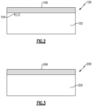
- FIG. 2 schematically illustrates a repaired article 100.
- the repaired article 100 includes a nonconforming article 102 with a nonconformance 104 which in this case is a dent/depression, hole, or the like.
- the nonconforming article is removed from the reactor in which CVI is being performed when the preform is only partially infiltrated with matrix material.
- the nonconforming article 102 is removed from the reactor towards the end of the CVI process, when at least about 50% of the desired matrix has been infiltrated into the preform. In a more particular example, at least about 75% of the desired matrix has been infiltrated into the preform when the nonconforming article 102 is removed from the CVI reactor.
- a machinable coating 106 is applied to a surface of the nonconforming article 102, filling in the nonconformance 104.
- the coating 106 is "machinable" in that it can be subject to grinding, ultrasonic machining, water guided laser, milling, reaming, or another machining method to reduce it thickness and/or smooth its surface without any negative effects to its integrity or the integrity of the CMC nonconforming article 102.
- the machinable coating 106 may include rare earth silicates, alkaline earth silicates, alkaline earth aluminosilicates, yttria-stabilized zirconia, alumina-stabilized zirconia, mullite, titania, chromia, silicon, silicon oxides, silicon carbides, silicon oxycarbides, barium-magnesium aluminosilicate, hafnium oxides such as hafnon, hafnium silicon oxides, alumina-stabilized zirconia, zirconium oxides such as zircon, yttrium oxides such as yttria, mullite, and combinations thereof.
- the machinable coating 106 includes at least one of hafnon, zircon, and mullite.
- the machinable coating 106 is then machined by grinding, ultrasonic machining, water guided laser, milling, reaming, or another machining method to reduce it thickness and/or smooth its surface, and to provide a desired surface profile for the repaired article.
- the repaired article 100 may then be returned to the reactor and CVI is completed until the desired matrix infiltration is complete.
- the machinable coating 106 is selected to withstanding the temperatures at which CVI occurs, which may be greater than about 1000 degrees C, without degrading or otherwise compromising its integrity.
- the machinable coating 106 is applied and machined after the CMC is completely infiltrated. In this case, the machinable coating would not need to be able to withstand the CVI process environment, and so material selection of the coating 106 would not need to be based on this criterion which may expand the possibilities. Still, any of the example materials discussed above could be used.
- FIG. 3 schematically illustrates another example repaired article 200.
- the repaired article 200 includes a nonconforming article 202 with a nonconformance which in this case is that the nonconforming article 202 is too small in some respect.
- the nonconforming article 202 is repaired in the same way as the nonconforming article 102 discussed above except that the machinable coating 206 is applied to build up a surface or area of the nonconforming article 202 such that the nonconforming article 202 has a desired geometry/size after being machined as described above. That is, the machinable coating 206 is first applied with a thickness/geometry that is greater than the desired thickness/geometry, and then machined down to the desired thickness/geometry as discussed above.
- the machinable coating 206 can have the same composition(s) as the machinable coating 106 discussed above.
Landscapes
- Chemical & Material Sciences (AREA)
- Engineering & Computer Science (AREA)
- Ceramic Engineering (AREA)
- Materials Engineering (AREA)
- Structural Engineering (AREA)
- Organic Chemistry (AREA)
- Inorganic Chemistry (AREA)
- Mechanical Engineering (AREA)
- Chemical Kinetics & Catalysis (AREA)
- Manufacturing & Machinery (AREA)
- General Engineering & Computer Science (AREA)
- Turbine Rotor Nozzle Sealing (AREA)
Abstract
A method of repairing a nonconforming article (102) includes applying a machinable coating (106) to an article (102) with a nonconformance (104). The article (102) includes a preform at least partially infiltrated with a matrix material, to form a repaired article (100). The method also includes machining the machinable coating (106) and completing infiltration of the repaired article (100) with the matrix material. A method of repairing an article (100) is also disclosed.
Description
- A gas turbine engine typically includes a fan section, a compressor section, a combustor section, and a turbine section. Air entering the compressor section is compressed and delivered into the combustion section where it is mixed with fuel and ignited to generate a high-speed exhaust gas flow. The high-speed exhaust gas flow expands through the turbine section to drive the compressor and the fan section.
- Various components of the gas turbine engine may be made of ceramic matrix composites. One method of making ceramic matrix composite articles is chemical vapor infiltration. However, when it is discovered during or after the chemical vapor infiltration process that an article includes a defect or nonconformance during the chemical vapor infiltration process, it is difficult to repair the article because most machining and repair processes are unsuitable for ceramic matrix composite components.
- A method of repairing a nonconforming article according to an exemplary embodiment of this disclosure, among other possible things includes applying a machinable coating to an article with a nonconformance. The article includes a preform at least partially infiltrated with a matrix material. The method also includes machining the machinable coating and completing infiltration of the repaired article with the matrix material.
- In a further example of the foregoing, the machining includes at least one of grinding, ultrasonic machining, water guided laser, milling, and reaming.
- In a further example of any of the foregoing, the coating includes at least one of rare earth silicates, alkaline earth silicates, alkaline earth aluminosilicates, yttria-stabilized zirconia, alumina-stabilized zirconia, hafnon, zircon, yttria, mullite, titania, chromia, silicon, silicon oxides, silicon carbides, silicon oxycarbides, barium-magnesium aluminosilicate, hafnium oxides, hafnium silicon oxides, alumina-stabilized zirconia, zirconium oxides, yttrium oxides, and combinations thereof.
- In a further example of any of the foregoing, the coating includes at least one of hafnon, zircon, and mullite.
- In a further example of any of the foregoing, the nonconformance includes at least one of a dent, a depression, or a hole.
- In a further example of any of the foregoing, the machinable coating fills in the nonconformance after the applying.
- In a further example of any of the foregoing, the nonconformance is that the article is smaller in a respect than a desired geometry of the article.
- In a further example of any of the foregoing, the applying includes applying the machinable coating to a geometry that is larger than the desired geometry in the respect.
- In a further example of any of the foregoing, the machining includes machining the machinable coating to the desired geometry.
- In a further example of any of the foregoing, the infiltration is by chemical vapor infiltration.
- In a further example of any of the foregoing, the preform includes ceramic-based reinforcements and the matrix is a ceramic-based matrix.
- A method of repairing an article according to an exemplary embodiment of this disclosure, among other possible things includes placing a preform including ceramic-based reinforcements into a reactor, flowing reactive gases through the reactor to infiltrate ceramic-based matrix material into the preform, and removing an at least partially-infiltrated article from the reactor. The at least partially-infiltrated article has a nonconformance. The method also includes repairing the nonconformance, replacing the at least partially-infiltrated article in the reactor, and flowing reactive gases through the reactor to complete infiltration of the ceramic-based matrix material into the at least partially-infiltrated article.
- In a further example of the foregoing, the repairing is by applying a machinable coating.
- In a further example of any of the foregoing, the nonconformance includes at least one of a dent, a depression, or a hole.
- In a further example of any of the foregoing, the machinable coating fills in the nonconformance after the applying.
- In a further example of any of the foregoing, the nonconformance is that the article is smaller in a respect than a desired geometry of the article.
- In a further example of any of the foregoing, the applying includes applying the machinable coating to a geometry that is larger than the desired geometry in the respect.
- In a further example of any of the foregoing, the method also includes machining the machinable coating to the desired geometry.
- In a further example of any of the foregoing, the partially-infiltrated article is at least 50% infiltrated with the ceramic-based matrix material at the removing step.
- In a further example of any of the foregoing, the partially-infiltrated article is at least 75% infiltrated with the ceramic-based matrix material at the removing step.
-
-
Figure 1 schematically illustrates an example gas turbine engine. -
Figure 2 schematically illustrates an article with a defect that has been repaired. -
Figure 3 schematically illustrates an article that has been repaired to address a size nonconformance. -
Figure 1 schematically illustrates agas turbine engine 20. Thegas turbine engine 20 is disclosed herein as a two-spool turbofan that generally incorporates afan section 22, acompressor section 24, a combustor section 26 and aturbine section 28. Thefan section 22 may include a single-stage fan 42 having a plurality offan blades 43. Thefan blades 43 may have a fixed stagger angle or may have a variable pitch to direct incoming airflow from an engine inlet. Thefan 42 drives air along a bypass flow path B in abypass duct 13 defined within ahousing 15 such as a fan case or nacelle, and also drives air along a core flow path C for compression and communication into the combustor section 26 then expansion through theturbine section 28. Asplitter 29 aft of thefan 42 divides the air between the bypass flow path B and the core flow path C. Thehousing 15 may surround thefan 42 to establish an outer diameter of thebypass duct 13. Thesplitter 29 may establish an inner diameter of thebypass duct 13. Although depicted as a two-spool turbofan gas turbine engine in the disclosed nonlimiting embodiment, it should be understood that the concepts described herein are not limited to use with two-spool turbofans as the teachings may be applied to other types of turbine engines including three-spool architectures. Theengine 20 may incorporate a variable area nozzle for varying an exit area of the bypass flow path B and/or a thrust reverser for generating reverse thrust. - The
exemplary engine 20 generally includes alow speed spool 30 and ahigh speed spool 32 mounted for rotation about an engine central longitudinal axis A relative to an enginestatic structure 36 viaseveral bearing systems 38. It should be understood thatvarious bearing systems 38 at various locations may alternatively or additionally be provided, and the location ofbearing systems 38 may be varied as appropriate to the application. - The
low speed spool 30 generally includes aninner shaft 40 that interconnects, a first (or low)pressure compressor 44 and a first (or low)pressure turbine 46. Theinner shaft 40 is connected to thefan 42 through a speed change mechanism, which in the exemplarygas turbine engine 20 is illustrated as a gearedarchitecture 48 to drive thefan 42 at a lower speed than thelow speed spool 30. Theinner shaft 40 may interconnect thelow pressure compressor 44 andlow pressure turbine 46 such that thelow pressure compressor 44 andlow pressure turbine 46 are rotatable at a common speed and in a common direction. In other embodiments, thelow pressure turbine 46 drives both thefan 42 andlow pressure compressor 44 through the gearedarchitecture 48 such that thefan 42 andlow pressure compressor 44 are rotatable at a common speed. Although this application discloses gearedarchitecture 48, its teaching may benefit direct drive engines having no geared architecture. Thehigh speed spool 32 includes anouter shaft 50 that interconnects a second (or high)pressure compressor 52 and a second (or high)pressure turbine 54. Acombustor 56 is arranged in theexemplary gas turbine 20 between thehigh pressure compressor 52 and thehigh pressure turbine 54. Amid-turbine frame 57 of the enginestatic structure 36 may be arranged generally between thehigh pressure turbine 54 and thelow pressure turbine 46. Themid-turbine frame 57 further supports bearingsystems 38 in theturbine section 28. Theinner shaft 40 and theouter shaft 50 are concentric and rotate viabearing systems 38 about the engine central longitudinal axis A which is collinear with their longitudinal axes. - Airflow in the core flow path C is compressed by the
low pressure compressor 44 then thehigh pressure compressor 52, mixed and burned with fuel in thecombustor 56, then expanded through thehigh pressure turbine 54 andlow pressure turbine 46. Themid-turbine frame 57 includesairfoils 59 which are in the core flow path C. Theturbines low speed spool 30 andhigh speed spool 32 in response to the expansion. It will be appreciated that each of the positions of thefan section 22,compressor section 24, combustor section 26,turbine section 28, and fandrive gear system 48 may be varied. For example,gear system 48 may be located aft of the low pressure compressor, or aft of the combustor section 26 or even aft ofturbine section 28, andfan 42 may be positioned forward or aft of the location ofgear system 48. - The
low pressure compressor 44,high pressure compressor 52,high pressure turbine 54 andlow pressure turbine 46 each include one or more stages having a row of rotatable airfoils. Each stage may include a row of vanes adjacent the rotatable airfoils. The rotatable airfoils are schematically indicated at 47, and the vanes are schematically indicated at 49. - The
engine 20 may be a high-bypass geared aircraft engine. The bypass ratio can be greater than or equal to 10.0 and less than or equal to about 18.0, or more narrowly can be less than or equal to 16.0. The gearedarchitecture 48 may be an epicyclic gear train, such as a planetary gear system or a star gear system. The epicyclic gear train may include a sun gear, a ring gear, a plurality of intermediate gears meshing with the sun gear and ring gear, and a carrier that supports the intermediate gears. The sun gear may provide an input to the gear train. The ring gear (e.g., star gear system) or carrier (e.g., planetary gear system) may provide an output of the gear train to drive thefan 42. A gear reduction ratio may be greater than or equal to 2.3, or more narrowly greater than or equal to 3.0, and in some embodiments the gear reduction ratio is greater than or equal to 3.4. The gear reduction ratio may be less than or equal to 4.0. The fan diameter is significantly larger than that of thelow pressure compressor 44. Thelow pressure turbine 46 can have a pressure ratio that is greater than or equal to 8.0 and in some embodiments is greater than or equal to 10.0. The low pressure turbine pressure ratio can be less than or equal to 13.0, or more narrowly less than or equal to 12.0.Low pressure turbine 46 pressure ratio is pressure measured prior to an inlet oflow pressure turbine 46 as related to the pressure at the outlet of thelow pressure turbine 46 prior to an exhaust nozzle. It should be understood, however, that the above parameters are only exemplary of one embodiment of a geared architecture engine and that the present invention is applicable to other gas turbine engines including direct drive turbofans. All of these parameters are measured at the cruise condition described below. - A significant amount of thrust is provided by the bypass flow B due to the high bypass ratio. The
fan section 22 of theengine 20 is designed for a particular flight condition -- typically cruise at about 0.8 Mach and about 35,000 feet (10,668 meters). The flight condition of 0.8 Mach and 35,000 ft (10,668 meters), with the engine at its best fuel consumption - also known as "bucket cruise Thrust Specific Fuel Consumption ('TSFC')" - is the industry standard parameter of lbm of fuel being burned divided by lbf of thrust the engine produces at that minimum point. The engine parameters described above, and those in the next paragraph are measured at this condition unless otherwise specified. - "Fan pressure ratio" is the pressure ratio across the
fan blade 43 alone, without a Fan Exit Guide Vane ("FEGV") system. A distance is established in a radial direction between the inner and outer diameters of thebypass duct 13 at an axial position corresponding to a leading edge of thesplitter 29 relative to the engine central longitudinal axis A. The fan pressure ratio is a spanwise average of the pressure ratios measured across thefan blade 43 alone over radial positions corresponding to the distance. The fan pressure ratio can be less than or equal to 1.45, or more narrowly greater than or equal to 1.25, such as between 1.30 and 1.40. "Corrected fan tip speed" is the actual fan tip speed in ft/sec divided by an industry standard temperature correction of [(Tram °R) / (518.7 °R)]0.5 (where °R = K x 9/5). The corrected fan tip speed can be less than or equal to 1150.0 ft / second (350.5 meters/second), and can be greater than or equal to 1000.0 ft / second (304.8 meters/second). - Ceramic matrix composites ("CMCs") are known in the art and will not be described in detail herein, but generally include ceramic-based reinforcements such as fibers (which may be continuous) disposed in a ceramic-based matrix material. CMCs can be used in various areas of the
engine 20, for instance, as airfoils. Chemical vapor infiltration (CVI) is a process that can be used to make CMC articles. CVI is known in the art and will not be described in detail herein, but generally includes placing a preform into a reactor, and flowing reactive gases through the reactor at high temperature to infiltrate matrix material into the preform. Occasionally during the CVI process it may be determined that an article being formed is nonconforming in that it has a scuff or dent, or is too small in certain respects. This application will describe a method of repairing nonconforming articles during the CVI process. -
Figure 2 schematically illustrates a repairedarticle 100. The repairedarticle 100 includes anonconforming article 102 with anonconformance 104 which in this case is a dent/depression, hole, or the like. In order to repair thenonconforming article 102 during the CVI process, the nonconforming article is removed from the reactor in which CVI is being performed when the preform is only partially infiltrated with matrix material. In one particular example, thenonconforming article 102 is removed from the reactor towards the end of the CVI process, when at least about 50% of the desired matrix has been infiltrated into the preform. In a more particular example, at least about 75% of the desired matrix has been infiltrated into the preform when thenonconforming article 102 is removed from the CVI reactor. - A
machinable coating 106 is applied to a surface of thenonconforming article 102, filling in thenonconformance 104. Thecoating 106 is "machinable" in that it can be subject to grinding, ultrasonic machining, water guided laser, milling, reaming, or another machining method to reduce it thickness and/or smooth its surface without any negative effects to its integrity or the integrity of the CMCnonconforming article 102. - The
machinable coating 106 may include rare earth silicates, alkaline earth silicates, alkaline earth aluminosilicates, yttria-stabilized zirconia, alumina-stabilized zirconia, mullite, titania, chromia, silicon, silicon oxides, silicon carbides, silicon oxycarbides, barium-magnesium aluminosilicate, hafnium oxides such as hafnon, hafnium silicon oxides, alumina-stabilized zirconia, zirconium oxides such as zircon, yttrium oxides such as yttria, mullite, and combinations thereof. In a particular example, themachinable coating 106 includes at least one of hafnon, zircon, and mullite. - The
machinable coating 106 is then machined by grinding, ultrasonic machining, water guided laser, milling, reaming, or another machining method to reduce it thickness and/or smooth its surface, and to provide a desired surface profile for the repaired article. - The repaired
article 100 may then be returned to the reactor and CVI is completed until the desired matrix infiltration is complete. In this case, themachinable coating 106 is selected to withstanding the temperatures at which CVI occurs, which may be greater than about 1000 degrees C, without degrading or otherwise compromising its integrity. In an alternative approach, themachinable coating 106 is applied and machined after the CMC is completely infiltrated. In this case, the machinable coating would not need to be able to withstand the CVI process environment, and so material selection of thecoating 106 would not need to be based on this criterion which may expand the possibilities. Still, any of the example materials discussed above could be used. -
Figure 3 schematically illustrates another example repairedarticle 200. The repairedarticle 200 includes anonconforming article 202 with a nonconformance which in this case is that thenonconforming article 202 is too small in some respect. Thenonconforming article 202 is repaired in the same way as thenonconforming article 102 discussed above except that themachinable coating 206 is applied to build up a surface or area of thenonconforming article 202 such that thenonconforming article 202 has a desired geometry/size after being machined as described above. That is, themachinable coating 206 is first applied with a thickness/geometry that is greater than the desired thickness/geometry, and then machined down to the desired thickness/geometry as discussed above. Themachinable coating 206 can have the same composition(s) as themachinable coating 106 discussed above. - The repairs discussed above enable a
nonconforming article 102/202 that may otherwise be discarded to be salvaged. - As used herein, the term "about" has the typical meaning in the art, however in a particular example "about" can mean deviations of up to 10% of the values described herein.
- Although a combination of features is shown in the illustrated examples, not all of them need to be combined to realize the benefits of various embodiments of this disclosure. In other words, a system designed according to an embodiment of this disclosure will not necessarily include all of the features shown in any one of the figures or all of the portions schematically shown in the figures. Moreover, selected features of one example embodiment may be combined with selected features of other example embodiments.
- Although an embodiment of this invention has been disclosed, a worker of ordinary skill in this art would recognize that certain modifications would come within the scope of this disclosure. For that reason, the following claims should be studied to determine the true scope and content of this disclosure.
Claims (15)
- A method of repairing a nonconforming article (102; 202), comprising:applying a machinable coating (106; 206) to an article (102; 202) with a nonconformance (104), the article (102; 202) including a preform at least partially infiltrated with a matrix material, to form a repaired article (100; 200);machining the machinable coating (106; 206); andcompleting infiltration of the repaired article (100; 200) with the matrix material.
- The method of claim 1, wherein the machining includes at least one of grinding, ultrasonic machining, water guided laser, milling, and reaming.
- The method of claim 1 or 2, wherein the coating (106; 206) includes at least one of rare earth silicates, alkaline earth silicates, alkaline earth aluminosilicates, yttria-stabilized zirconia, alumina-stabilized zirconia, hafnon, zircon, yttria, mullite, titania, chromia, silicon, silicon oxides, silicon carbides, silicon oxycarbides, barium-magnesium aluminosilicate, hafnium oxides, hafnium silicon oxides, alumina-stabilized zirconia, zirconium oxides, yttrium oxides, and combinations thereof.
- The method of claim 1, 2 or 3, wherein the nonconformance (104) includes at least one of a dent, a depression, or a hole.
- The method of claim 4, wherein the machinable coating (106) fills in the nonconformance (104) after the applying.
- The method of claim 1, 2 or 3, wherein the nonconformance is that the article (202) is smaller in a respect than a desired geometry of the article (202).
- The method of claim 6, wherein the applying includes applying the machinable coating (106; 206) to a geometry that is larger than the desired geometry in the respect.
- The method of claim 7, wherein the machining includes machining the machinable coating (106; 206) to the desired geometry.
- The method of any preceding claim, wherein the infiltration is by chemical vapor infiltration.
- The method of any preceding claim, wherein the preform includes ceramic-based reinforcements and the matrix is a ceramic-based matrix.
- A method of repairing an article (102; 202), comprising:placing a preform including ceramic-based reinforcements into a reactor;flowing reactive gases through the reactor to infiltrate ceramic-based matrix material into the preform;removing an at least partially-infiltrated article (102; 202) from the reactor, the at least partially-infiltrated article (102; 202) having a nonconformance (104);repairing the nonconformance (104);replacing the at least partially-infiltrated article (102; 202) in the reactor; andflowing reactive gases through the reactor to complete infiltration of the ceramic-based matrix material into the at least partially-infiltrated article (102; 202).
- The method of claim 11, wherein the repairing is by applying a machinable coating (106; 206).
- The method of claim 12, wherein the nonconformance (104) includes at least one of a dent, a depression, or a hole, and, optionally, the machinable coating (106) fills in the nonconformance (104) after the applying.
- The method of claim 12, wherein the nonconformance is that the article (202) is smaller in a respect than a desired geometry of the article (202), wherein, optionally, the applying includes applying the machinable coating (206) to a geometry that is larger than the desired geometry in the respect, and, further optionally, the method further comprising machining the machinable coating (206) to the desired geometry.
- The method of any of claims 11 to 14, wherein the partially-infiltrated article (102; 202) is at least 50% infiltrated with the ceramic-based matrix material at the removing step, and, optionally, the partially-infiltrated article (102; 202) is at least 75% infiltrated with the ceramic-based matrix material at the removing step.
Applications Claiming Priority (1)
| Application Number | Priority Date | Filing Date | Title |
|---|---|---|---|
| US18/080,468 US12138720B2 (en) | 2022-12-13 | 2022-12-13 | Article and method of making an article by chemical vapor infiltration |
Publications (1)
| Publication Number | Publication Date |
|---|---|
| EP4385969A1 true EP4385969A1 (en) | 2024-06-19 |
Family
ID=89222764
Family Applications (1)
| Application Number | Title | Priority Date | Filing Date |
|---|---|---|---|
| EP23216448.3A Pending EP4385969A1 (en) | 2022-12-13 | 2023-12-13 | Article and method of making an article by chemical vapor infiltration |
Country Status (2)
| Country | Link |
|---|---|
| US (1) | US12138720B2 (en) |
| EP (1) | EP4385969A1 (en) |
Families Citing this family (1)
| Publication number | Priority date | Publication date | Assignee | Title |
|---|---|---|---|---|
| US20240190780A1 (en) * | 2022-12-13 | 2024-06-13 | Raytheon Technologies Corporation | Article and method of making a ceramic matrix composite article |
Citations (1)
| Publication number | Priority date | Publication date | Assignee | Title |
|---|---|---|---|---|
| FR2850649A1 (en) * | 2003-01-30 | 2004-08-06 | Snecma Propulsion Solide | PROCESS FOR THE SURFACE TREATMENT OF A PART OF THERMOSTRUCTURAL COMPOSITE MATERIAL AND APPLICATION TO THE BRAZING OF PARTS OF THERMOSTRUCTURAL COMPOSITE MATERIAL |
Family Cites Families (29)
| Publication number | Priority date | Publication date | Assignee | Title |
|---|---|---|---|---|
| GB1581534A (en) | 1976-09-20 | 1980-12-17 | Ici Ltd | Electrolytic cell |
| US5439348A (en) | 1994-03-30 | 1995-08-08 | United Technologies Corporation | Turbine shroud segment including a coating layer having varying thickness |
| US6418618B1 (en) | 2000-04-11 | 2002-07-16 | General Electric Company | Method of controlling the side wall thickness of a turbine nozzle segment for improved cooling |
| FR2844933B1 (en) | 2002-09-20 | 2004-11-26 | Sagem | IMPROVEMENTS ON HIGH POWER MOTORS. |
| US7686990B2 (en) * | 2004-12-31 | 2010-03-30 | General Electric Company | Method of producing a ceramic matrix composite article |
| US7771159B2 (en) | 2006-10-16 | 2010-08-10 | General Electric Company | High temperature seals and high temperature sealing systems |
| US20130004320A1 (en) | 2011-06-28 | 2013-01-03 | United Technologies Corporation | Method of rotated airfoils |
| US10113435B2 (en) | 2011-07-15 | 2018-10-30 | United Technologies Corporation | Coated gas turbine components |
| US20160298467A1 (en) | 2013-11-18 | 2016-10-13 | United Technologies Corporation | Article having variable coating |
| US10648075B2 (en) * | 2015-03-23 | 2020-05-12 | Goodrich Corporation | Systems and methods for chemical vapor infiltration and densification of porous substrates |
| US10024175B2 (en) | 2015-05-26 | 2018-07-17 | Rolls-Royce Corporation | Cooling holes manufactured with EBC in place |
| US10401028B2 (en) | 2015-06-05 | 2019-09-03 | Rolls-Royce American Technologies, Inc. | Machinable CMC insert |
| US10458653B2 (en) | 2015-06-05 | 2019-10-29 | Rolls-Royce Corporation | Machinable CMC insert |
| US10465534B2 (en) | 2015-06-05 | 2019-11-05 | Rolls-Royce North American Technologies, Inc. | Machinable CMC insert |
| US10472976B2 (en) | 2015-06-05 | 2019-11-12 | Rolls-Royce Corporation | Machinable CMC insert |
| US20170030211A1 (en) | 2015-07-28 | 2017-02-02 | General Electric Company | Seals with a conformable coating for turbomachinery |
| US10100656B2 (en) | 2015-08-25 | 2018-10-16 | General Electric Company | Coated seal slot systems for turbomachinery and methods for forming the same |
| US20180311934A1 (en) * | 2017-04-28 | 2018-11-01 | Rolls-Royce Corporation | Seal coating for ceramic matrix composite |
| US10618128B2 (en) * | 2017-07-18 | 2020-04-14 | General Electric Company | Method for closing a hole in a metal article |
| US20200165713A1 (en) | 2017-07-18 | 2020-05-28 | General Electric Company | Freestanding ceramic seal for a gas turbine |
| ES3035018T3 (en) | 2017-11-20 | 2025-08-28 | Agie Charmilles Sa | Method and device for machining shapes using electrical machining |
| US11292217B2 (en) * | 2018-05-31 | 2022-04-05 | General Electric Company | Composite component void repair |
| US10934873B2 (en) | 2018-11-07 | 2021-03-02 | General Electric Company | Sealing system for turbine shroud segments |
| US20200141276A1 (en) | 2018-11-07 | 2020-05-07 | General Electric Company | Turbine shroud with lapped seal segments |
| EP3924141A1 (en) | 2019-02-15 | 2021-12-22 | Corning Incorporated | Extrusion dies and methods of manufacturing the same |
| US11143040B2 (en) | 2019-10-02 | 2021-10-12 | Raytheon Technologies Corporation | Ceramic matrix composite rotor blade attachment and method of manufacture therefor |
| US11466585B2 (en) | 2019-11-06 | 2022-10-11 | Raytheon Technologies Corporation | Blade outer air seal arrangement and method of sealing |
| US12071380B2 (en) | 2020-09-16 | 2024-08-27 | Rolls-Royce High Temperature Composites, Inc. | Method to fabricate a machinable ceramic matrix composite |
| US12017297B2 (en) * | 2021-12-22 | 2024-06-25 | Spirit Aerosystems, Inc. | Method for manufacturing metal matrix composite parts |
-
2022
- 2022-12-13 US US18/080,468 patent/US12138720B2/en active Active
-
2023
- 2023-12-13 EP EP23216448.3A patent/EP4385969A1/en active Pending
Patent Citations (1)
| Publication number | Priority date | Publication date | Assignee | Title |
|---|---|---|---|---|
| FR2850649A1 (en) * | 2003-01-30 | 2004-08-06 | Snecma Propulsion Solide | PROCESS FOR THE SURFACE TREATMENT OF A PART OF THERMOSTRUCTURAL COMPOSITE MATERIAL AND APPLICATION TO THE BRAZING OF PARTS OF THERMOSTRUCTURAL COMPOSITE MATERIAL |
Non-Patent Citations (1)
| Title |
|---|
| ZHANG JIAXIN ET AL: "Effect of a diffusion-enhancing hole on the densification of a thick-section 2D C/SiC composite", JOURNAL OF THE EUROPEAN CERAMIC SOCIETY, ELSEVIER, AMSTERDAM, NL, vol. 39, no. 15, 26 July 2019 (2019-07-26), pages 4609 - 4616, XP085810536, ISSN: 0955-2219, [retrieved on 20190726], DOI: 10.1016/J.JEURCERAMSOC.2019.07.043 * |
Also Published As
| Publication number | Publication date |
|---|---|
| US12138720B2 (en) | 2024-11-12 |
| US20240189951A1 (en) | 2024-06-13 |
Similar Documents
| Publication | Publication Date | Title |
|---|---|---|
| US12607129B2 (en) | Attachment region for CMC components | |
| US11125093B2 (en) | Vane with L-shaped seal | |
| EP4385969A1 (en) | Article and method of making an article by chemical vapor infiltration | |
| EP4379192A1 (en) | Seal slot with coating | |
| EP4379191A1 (en) | Seal slot with coating and method of coating a seal slot | |
| EP4379190B1 (en) | Removable layer to adjust mount structure of a turbine vane for re-stagger | |
| EP4617475A2 (en) | Variable thickness machinable coating for platform seals | |
| US20240190780A1 (en) | Article and method of making a ceramic matrix composite article | |
| US11220917B1 (en) | Diffused cooling arrangement for gas turbine engine components | |
| US11976571B1 (en) | Machinable coating with thermal protection | |
| US12359575B2 (en) | Machinable coating with thermal protection | |
| US20240271537A1 (en) | Machinable coating for damping | |
| US12571315B2 (en) | Blade with damper land | |
| US20240246872A1 (en) | Sealing interface | |
| EP4219904B1 (en) | Ceramic matrix composite article and method of making the same | |
| EP4230404A1 (en) | Preform and method of making a ceramic matrix composite article | |
| EP4603246A1 (en) | Multi-piece mandrel for building up airfoil structure | |
| US20240141997A1 (en) | Seal with coating | |
| US20250257666A1 (en) | Ceramic matrix composite component with coating | |
| US20240044260A1 (en) | Ceramic matrix composite article and method of making the same |
Legal Events
| Date | Code | Title | Description |
|---|---|---|---|
| PUAI | Public reference made under article 153(3) epc to a published international application that has entered the european phase |
Free format text: ORIGINAL CODE: 0009012 |
|
| STAA | Information on the status of an ep patent application or granted ep patent |
Free format text: STATUS: THE APPLICATION HAS BEEN PUBLISHED |
|
| AK | Designated contracting states |
Kind code of ref document: A1 Designated state(s): AL AT BE BG CH CY CZ DE DK EE ES FI FR GB GR HR HU IE IS IT LI LT LU LV MC ME MK MT NL NO PL PT RO RS SE SI SK SM TR |
|
| STAA | Information on the status of an ep patent application or granted ep patent |
Free format text: STATUS: REQUEST FOR EXAMINATION WAS MADE |
|
| 17P | Request for examination filed |
Effective date: 20241212 |