EP4385928A1 - Tension abnormality detection device, tension abnormality detection method, and tension abnormality detection program - Google Patents
Tension abnormality detection device, tension abnormality detection method, and tension abnormality detection program Download PDFInfo
- Publication number
- EP4385928A1 EP4385928A1 EP23209688.3A EP23209688A EP4385928A1 EP 4385928 A1 EP4385928 A1 EP 4385928A1 EP 23209688 A EP23209688 A EP 23209688A EP 4385928 A1 EP4385928 A1 EP 4385928A1
- Authority
- EP
- European Patent Office
- Prior art keywords
- tension
- waveform
- thread
- abnormality
- abnormality detection
- Prior art date
- Legal status (The legal status is an assumption and is not a legal conclusion. Google has not performed a legal analysis and makes no representation as to the accuracy of the status listed.)
- Granted
Links
Images






Classifications
-
- B—PERFORMING OPERATIONS; TRANSPORTING
- B65—CONVEYING; PACKING; STORING; HANDLING THIN OR FILAMENTARY MATERIAL
- B65H—HANDLING THIN OR FILAMENTARY MATERIAL, e.g. SHEETS, WEBS, CABLES
- B65H63/00—Warning or safety devices, e.g. automatic fault detectors, stop-motions ; Quality control of the package
- B65H63/02—Warning or safety devices, e.g. automatic fault detectors, stop-motions ; Quality control of the package responsive to reduction in material tension, failure of supply, or breakage, of material
-
- B—PERFORMING OPERATIONS; TRANSPORTING
- B65—CONVEYING; PACKING; STORING; HANDLING THIN OR FILAMENTARY MATERIAL
- B65H—HANDLING THIN OR FILAMENTARY MATERIAL, e.g. SHEETS, WEBS, CABLES
- B65H63/00—Warning or safety devices, e.g. automatic fault detectors, stop-motions ; Quality control of the package
- B65H63/04—Warning or safety devices, e.g. automatic fault detectors, stop-motions ; Quality control of the package responsive to excessive tension or irregular operation of apparatus
-
- D—TEXTILES; PAPER
- D01—NATURAL OR MAN-MADE THREADS OR FIBRES; SPINNING
- D01H—SPINNING OR TWISTING
- D01H13/00—Other common constructional features, details or accessories
- D01H13/14—Warning or safety devices, e.g. automatic fault detectors, stop motions ; Monitoring the entanglement of slivers in drafting arrangements
- D01H13/16—Warning or safety devices, e.g. automatic fault detectors, stop motions ; Monitoring the entanglement of slivers in drafting arrangements responsive to reduction in material tension, failure of supply, or breakage, of material
-
- D—TEXTILES; PAPER
- D01—NATURAL OR MAN-MADE THREADS OR FIBRES; SPINNING
- D01H—SPINNING OR TWISTING
- D01H13/00—Other common constructional features, details or accessories
- D01H13/14—Warning or safety devices, e.g. automatic fault detectors, stop motions ; Monitoring the entanglement of slivers in drafting arrangements
- D01H13/20—Warning or safety devices, e.g. automatic fault detectors, stop motions ; Monitoring the entanglement of slivers in drafting arrangements responsive to excessive tension or irregular operation of apparatus
-
- B—PERFORMING OPERATIONS; TRANSPORTING
- B65—CONVEYING; PACKING; STORING; HANDLING THIN OR FILAMENTARY MATERIAL
- B65H—HANDLING THIN OR FILAMENTARY MATERIAL, e.g. SHEETS, WEBS, CABLES
- B65H2701/00—Handled material; Storage means
- B65H2701/30—Handled filamentary material
- B65H2701/31—Textiles threads or artificial strands of filaments
Definitions
- the present disclosure relates to a tension abnormality detection device, a tension abnormality detection method, and a tension abnormality detection program.
- Patent Document 1 JP 2002-302824A discloses a method for detecting an abnormality in a step of using a winding device to wind a thread spun from a spinning device.
- the thread path is provided with a tension measurement means.
- the tension measurement means measures the tension of the thread and obtains the average value of the tension and the standard deviation of the tension during a predetermined sampling period.
- the obtained average value of the tension is compared with the upper and lower thresholds therefor, and it is detected whether or not there is an abnormality by comparing the obtained standard deviation of the tension and the upper threshold.
- JP 2002-302824A is an example of related art.
- the present disclosure has been made in view of the above circumstances, and a main purpose thereof is to provide a tension abnormality detection device, a tension abnormality detection method, and a tension abnormality detection program, according to which it is possible to accurately detect various abnormalities related to tension of a thread wound by a thread winding machine.
- a tension abnormality detection device includes a control device and a tension sensor for detecting tension of a thread wound by a thread winding machine.
- the control device executes processing for acquiring an autoencoder trained to compress a normal tension waveform and then restore the normal tension waveform, and processing for detecting an abnormality in the tension of the thread wound by the thread winding machine, based on a degree of similarity between an input tension waveform obtained from the tension sensor and an output tension waveform obtained by inputting the input tension waveform to the autoencoder.
- an autoencoder trained based on a tension waveform with normal tension is used to detect an abnormality in the tension of a thread. For this reason, various abnormalities that deviate from normal tension can be detected. For example, abnormalities that cannot be detected with only the magnitude of the tension or the degree of change in the tension are detected.
- control device further executes training processing for generating the autoencoder using a normal tension waveform.
- the training processing is executed by the tension abnormality detection device. Due to the tension abnormality detection device having a learning function, the tension abnormality detection device can generate the autoencoder by itself.
- the thread winding machine winds thread on a bobbin while causing the thread to perform a traversing motion
- the tension sensor is configured to detect tension by intermittently coming into contact with the thread according to the traversing motion of the thread.
- the data detected by the tension sensor that intermittently comes into contact with the thread includes not only the maximum value of the tension but also a change trend indicating how the tension changes over time.
- the tension waveform includes a large number of features, and therefore an autoencoder for accurately detecting the degree of abnormality in the tension of the thread is generated.
- abnormality of tension is detected if the degree of similarity is greater than or equal to a predetermined threshold. Normality of tension is detected if the degree of similarity is less than the predetermined threshold.
- the tension abnormality detection device can detect a tension abnormality according to the threshold.
- the tension abnormality detection device further includes a display unit.
- the control device further executes processing for creating a graph showing change over time in the degree of similarity and displaying the graph on the display unit.
- control device executes the detecting processing while the thread winding machine winds the thread.
- the tension abnormality detection device can detect the degree of abnormality in the tension in real time or at a timing close to real time. For this reason, if the tension is abnormal, the administrator or operator can also perform processing such as interrupting the winding.
- control device further executes processing for acquiring an estimation model trained to receive input of a tension waveform and output a type of the abnormality, and processing for, if abnormality of tension is detected in the detecting processing, identifying the type of the abnormality based on the input tension waveform and the estimation model.
- the tension abnormality detection device can not only detect the occurrence of a tension abnormality, but also identify the type of the tension abnormality that has occurred.
- a tension abnormality detection method to be performed by a tension abnormality detection device includes a tension sensor for detecting tension of a thread wound by the thread winding machine.
- the tension abnormality detection method includes a step of acquiring an autoencoder trained to compress a normal tension waveform and then restore the normal tension waveform; and a step of detecting abnormality in the tension of the thread wound by the thread winding machine, based on a degree of similarity between an input tension waveform obtained from the tension sensor and an output tension waveform obtained by inputting the input tension waveform to the autoencoder.
- an autoencoder trained based on a tension waveform with normal tension is used to detect abnormality in the tension of a thread. For this reason, various abnormalities that deviate from normal tension can be detected. For example, abnormalities that cannot be detected with only the magnitude of the tension or degree of change in the tension are detected.
- the tension abnormality detection device includes a tension sensor for detecting tension of a thread wound by a thread winding machine.
- the tension abnormality detection program causes the tension abnormality detection device to execute: a step of acquiring an autoencoder trained to compress a normal tension waveform and then restore the normal tension waveform; and a step of detecting abnormality in the tension of the thread wound by the thread winding machine based on a degree of similarity between an input tension waveform obtained from the tension sensor and an output tension waveform obtained by inputting the input tension waveform to the autoencoder.
- an autoencoder trained based on a tension waveform with normal tension is used to detect abnormality in the tension of a thread. For this reason, various abnormalities that deviate from normal tension can be detected. For example, abnormalities that cannot be detected with only the magnitude of the tension or the degree of change in the tension are detected.
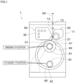
- FIG. 1 is a front view of a thread winding machine 1 according to an embodiment of the present disclosure.
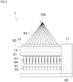
- FIG. 2 is a side view of the thread winding machine 1.
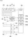
- FIG. 3 is a block diagram of the thread winding machine 1.
- upstream or downstream in the travel direction of the thread is simply referred to as upstream or downstream in some cases.
- a spinning machine (not shown) is arranged upstream of the thread winding machine 1 shown in FIG. 1 .
- the spinning machine produces a thread 93 and supplies the thread 93 to the thread winding machine 1.
- the thread winding machine 1 winds the thread 93 around a bobbin 91 to manufacture a package 94.
- the package 94 is formed by winding the thread 93 on the bobbin 91 at an upper winding position to form a thread layer.
- the thread 93 is not wound on the bobbin 91 at the lower standby position.
- the thread 93 is a highly stretchable synthetic thread such as nylon or polyester. More specifically, the thread 93 is, for example, FDY (Fully Draw Yarn) or POY (Partially Oriented Yarn). However, the types of the thread 93 are not limited to these, and a tension abnormality detection device 10, which will be described later, can be applied also to threads other than those described above.
- a plurality of threads 93 arranged side by side in the axial direction of the first bobbin holder 41 (second bobbin holder 42) are supplied from a thread feed roller 100 to the thread winding machine 1 from the spinning machine.
- a plurality of bobbins 91 are arranged side by side in the axial direction of the first bobbin holder 41 (second bobbin holder 42).
- the thread winding machine 1 winds a plurality of threads 93 onto the bobbins 91 to manufacture a plurality of packages 94.
- the thread winding machine 1 includes a frame 11, a support point guide 12, a first housing 20, a second housing 30, and a turret plate (bobbin holder moving mechanism) 40.
- the frame 11 is a member that holds each part of the thread winding machine 1.
- the first housing 20 and the second housing 30 are mounted on the frame 11.
- the first housing 20 and the second housing 30 can move up and down with respect to the frame 11.
- the support point guide 12 is arranged on the frame 11.
- the support point guide 12 guides the thread 93 supplied to the thread winding machine 1 from the spinning machine.
- the support point guide 12 has a wall portion that comes into contact with the thread 93, and restricts the position of the thread 93 such that the thread 93 does not deviate from the thread path.
- a traverse device 21 is attached to the first housing 20.
- the traverse device 21 causes the thread 93 fed downstream to perform a traversing motion by moving back and forth on the winding width of the package 94 along the axial direction of a later-described first bobbin holder 41 while a later-described traverse guide 23 engages with the thread 93.
- a thread layer is formed on the bobbin 91 or the package 94 by this traversing motion of the thread 93.
- the traverse device 21 includes a traverse cam 22 and a traverse guide 23.
- the traverse cam 22 is a roller-shaped member arranged parallel to the bobbin 91 or the package 94. A spiral cam groove is formed on the outer peripheral surface of the traverse cam 22.
- the traverse cam 22 is rotationally driven by a traverse motor 51.
- the traverse motor 51 is controlled by a later-described control device 50.
- the traverse guide 23 is a part that engages with the thread 93.
- the leading end of the traverse guide 23 has, for example, a substantially U-shaped guide portion, which engages with the thread 93 so as to sandwich the thread 93 in the winding width direction.
- the base end of the traverse guide 23 is located in the cam groove of the traverse cam 22. With this configuration, by rotationally driving the traverse cam 22, the traverse guide 23 can be moved back and forth in the winding width direction with the support point guide 12 serving as a support point.
- a contact roller 31 is rotatably mounted on the second housing 30.
- the contact roller 31 is driven to rotate while in contact with the thread layer of the package 94 with a predetermined pressure, whereby the thread 93 from the traverse guide 23 is fed to the thread layer of the package 94 and the thread layer shape of the package 94 is adjusted.
- the contact roller 31 may be rotationally driven using a drive unit such as a motor
- An operation panel 32 is provided on the second housing 30.
- the operation panel 32 is a device operated by an operator.
- the operator gives instructions to the thread winding machine 1 by operating the operation panel 32. Instructions given by the operator include, for example, starting winding, stopping winding, and changing winding conditions.
- a tension sensor 13 is provided on the thread path from the spinning machine to the traverse device 21. Specifically, the tension sensor 13 is provided downstream of the support point guide 12 and upstream of the traverse device 21 in the travel direction of the thread 93. Accordingly, the tension sensor 13 detects the tension of the thread 93 that is moved back and forth by the traverse device 21.
- the tension sensor 13 has a pair of arm portions (not shown). One arm portion comes into contact with the thread 93 at one end of the traversing motion. The other arm portion comes into contact with the thread 93 at the other end of the traversing motion. That is, the tension sensor 13 intermittently comes into contact with the thread 93 performing a traversing motion.
- a strain gauge is provided on the arm portion, and the strain of the arm portion detected by the strain gauge correlates with the tension of the thread 93. Accordingly, the tension of the thread 93 can be obtained based on the signal output by the strain gauge.
- a signal indicating the value of the tension detected by the tension sensor 13 is output to the control device 50, which will be described later. Also, the signal output by the tension sensor 13 includes a tension waveform that indicates change in the tension over time.
- the tension sensor 13 described above is merely an example, and a tension sensor 13 having a configuration different from that of the present embodiment may also be used.
- the tension sensor 13 is not limited to intermittently coming into contact with the thread 93, and may be configured to continuously be in contact with the thread 93.
- the tension sensor 13 may detect tension using a spring or a piezoelectric element instead of the strain gauge.
- the thread winding machine 1 has a display unit 14.
- the display unit 14 is a display capable of displaying information.
- the display unit 14 is, for example, a liquid crystal display or an organic EL display.
- the display unit 14 displays an image output by the control device 50, which will be described later, on a screen.
- the turret plate 40 is a disk-shaped member.
- the turret plate 40 is rotatably mounted on the frame 11.
- the turret plate 40 can rotate using a normal line passing through the center of the disk as a rotation axis.
- the turret plate 40 is rotationally driven by a turret motor 53 shown in FIG. 3 .
- the turret motor 53 is controlled by the control device 50, which will be described later.
- a first bobbin holder 41 and a second bobbin holder 42 are respectively provided at two locations on the turret plate 40 that oppose each other across the center of the disk.
- a plurality of bobbins 91 can be mounted side by side in the axial direction of the first bobbin holder 41 on the first bobbin holder 41.
- the plurality of bobbins 91 can be mounted side by side in the axial direction of the second bobbin holder 42 on the second bobbin holder 42.
- the positions of the first bobbin holder 41 and the second bobbin holder 42 can be changed by rotating the turret plate 40. Note that another device may be used instead of the turret plate 40, as long as the positions of the first bobbin holder 41 and the second bobbin holder 42 can be changed.
- the first bobbin holder 41 is rotatable with respect to the turret plate 40 using the axis position of the first bobbin holder 41 as the center of rotation.
- the first bobbin holder 41 is rotationally driven by a first bobbin holder motor 54 shown in FIG. 3 .
- the second bobbin holder 42 is rotatable with respect to the turret plate 40 using the axis position of the second bobbin holder 42 as the center of rotation.
- the second bobbin holder 42 is rotationally driven by a second bobbin holder motor 55 shown in FIG. 3 .
- the first bobbin holder motor 54 and the second bobbin holder motor 55 are controlled by the control device 50, which will be described later.
- FIG. 1 shows a state in which the bobbin holders 41 and 42 are arranged side by side in the up-down direction. At this time, the position of the bobbin holders 41 and 42 on the higher side is the winding position, and the position of the bobbin holders 41 and 42 on the lower side is the standby position.
- the thread winding machine 1 produces the package 94 by winding the thread 93 around the bobbins 91 of the bobbin holders 41 and 42 at the winding position.
- the positions of the first bobbin holder 41 and the second bobbin holder 42 are switched by rotating the turret plate 40. Thereafter, the packages 94 of the first bobbin holder 41 that are fully wound and are at the standby position are collected, and the thread 93 is wound onto the bobbins 91 of the second bobbin holder 42 that are at the winding position. New bobbins 91 are mounted on the first bobbin holder 41 from which the packages 94 have been collected.
- the control device 50 includes a control unit 50a, a training unit 50b, a detection unit 50c, and a storage unit 50d.
- the control device 50 is configured as a known computer, and includes a CPU (Central Processing Unit), RAM (Random Access Memory), SSD (Solid State Drive), and the like.
- a CPU is a type of processor.
- Programs and data for controlling the thread winding machine 1 are stored in advance in the SSD.
- the SSD stores tension input from the tension sensor 13 in chronological order. Due to the CPU reading out the program to the RAM and executing the program, the control device 50 can operate as the control unit 50a, the training unit 50b, and the detection unit 50c.
- the SSD corresponds to the storage unit 50d.
- an HDD Hard Disk Drive
- flash memory may be used instead of the SSD.
- a storage that is provided outside of the control device 50 and can communicate with the control device 50 may also be used as the storage unit.
- the control unit 50a performs overall control of the control device 50.
- the control unit 50a processes the data input to the control device 50 from the outside or data stored in the storage unit 50d.
- the control unit 50a stores the data obtained through this processing in the storage unit 50d or outputs the data to the outside of the control device 50.
- the training unit 50b performs processing for constructing a conversion model using machine learning. Details of the conversion model constructed by the training unit 50b will be described later.
- the detection unit 50c performs detection processing for detecting an abnormality based on data externally input to the control device 50 and the conversion model constructed by the training unit 50b and stored in the storage unit 50d.
- the storage unit 50d stores data according to the processing of the control unit 50a.
- FIG. 3 shows the tension abnormality detection device 10.
- the tension abnormality detection device 10 detects the degree of abnormality in the tension of the thread 93 wound by the thread winding machine 1.
- the tension abnormality detection device 10 includes a control device 50, a tension sensor 13, and a display unit 14.
- the control device 50 performs the following processing as a component of the tension abnormality detection device 10.
- control unit 50a outputs data to the training unit 50b and the detection unit 50c for processing.
- the control unit 50a causes the storage unit 50d to store data obtained by the training unit 50b and the detection unit 50c performing processing.
- control unit 50a stores the tension waveform detected by the tension sensor 13 in the storage unit 50d.
- a traverse motor 51, a turret motor 53, a first bobbin holder motor 54, and a second bobbin holder motor 55 are further included as objects to be controlled by the control unit 50a.
- the training unit 50b constructs a conversion model by performing machine learning based on a tension waveform stored in the storage unit 50d or a tension waveform based on the detection value of the tension input from the tension sensor 13.
- the detection unit 50c detects a degree of abnormality in the tension of the thread 93 wound by the thread winding machine 1 and determines whether or not there is an abnormality based on data input to the control device 50 from the outside (specifically, tension detected by the tension sensor 13) and a conversion model constructed by the training unit 50b and stored in the storage unit 50d.
- the determination result obtained through the processing of the detection unit 50c is output to the outside or stored in the storage unit 50d by the control unit 50a.
- the storage unit 50d stores data obtained through the processing of the control unit 50a, the training unit 50b, and the detection unit 50c, as described above.
- the conversion model is an autoencoder, and is constructed by the training unit 50b performing the following machine learning.
- the operator or administrator instructs the training unit 50b to start machine learning.
- the training unit 50b requests the tension sensor 13 to transmit the detection value of the tension.
- the tension sensor 13 outputs the detection value of the tension to the training unit 50b.
- the training unit 50b buffers the detection value of the tension input from the tension sensor 13.
- the processing for acquiring and buffering the detection value of the tension by the training unit 50b is performed repeatedly. Thereafter, the training unit 50b performs machine learning on the buffered detection value of the tension to construct a conversion model.
- the detection value of the tension output by the tension sensor 13 may be stored in the storage unit 50d based on a request from the training unit 50b, and the training unit 50b may construct the conversion model by performing machine learning based on the content stored in the storage unit 50d.
- the conversion model constructed by the training unit 50b is stored in the storage unit 50d and set in the detection unit 50c. This completes the machine learning.
- the tension waveform is triangular. Also, training data for creating a conversion model is a tension waveform with normal tension. Only tension waveforms with normal tension are used to create the conversion model, and tension waveforms with abnormal tension are not used. Since the frequency of occurrence of an abnormality in tension is generally low, it is easy to prepare a tension waveform with normal tension.
- a conversion model is constructed by performing unsupervised learning using the above training data for an input layer, an intermediate layer, and an output layer in a multi-layer neural network.
- the learning performed here is deep learning, and since feature amounts are specified through learning, input of feature amounts is unnecessary.
- By setting a tension waveform with normal tension for the conversion model constructed by performing this learning important feature amounts included in the tension waveform are extracted and compressed into an intermediate layer (hidden layer), and thereafter a restored tension waveform is generated based on the feature amounts. That is, the conversion model is used such that if the input tension waveform is a tension waveform with normal tension, the output tension waveform will generate a tension waveform similar to the input tension waveform.
- the method for constructing a conversion model of the present embodiment is an example, and another method can also be used.
- the conversion model is used by the detection unit 50c. Specifically, the detection unit 50c generates the output tension waveform based on the input tension waveform and the conversion model. Here, if the input tension waveform is a tension waveform with normal tension, the detection unit 50c generates a tension waveform similar to the input tension waveform as the output tension waveform. Then, if the input tension waveform is an abnormal tension waveform, the detection unit 50c generates a tension waveform different from the input tension waveform as the output tension waveform.
- FIG. 5 shows a tension waveform (input tension waveform) in which no tension abnormality occurs, and an output tension waveform generated by the detection unit 50c based on the input tension waveform and the conversion model. Since the input tension waveform does not include a tension abnormality, the input tension waveform and the output tension waveform are substantially the same and have a high degree of similarity.
- FIG. 6 shows a tension waveform (input tension waveform) in which a tension abnormality occurs, and an output tension waveform generated by the detection unit 50c based on the input tension waveform and the conversion model. Since the input tension waveform includes a tension abnormality, the degree of similarity between the input tension waveform and the output tension waveform is low in the time span when the tension abnormality occurs (the time span indicated by the dashed-line ellipse).
- the detection unit 50c compares the input tension waveform and the output tension waveform, and detects the degree of abnormality in the tension of the thread 93 based on the degree of similarity between the input tension waveform and the output tension waveform.
- Various methods for obtaining a degree of correlation between two pieces of data can be used to compare the input tension waveform and the output tension waveform.
- the Mahalanobis distance is used.
- the Mahalanobis distance is a virtual distance calculated with consideration given to the correlative relationship, and the distance decreases when the correlation is high. Note that since the Mahalanobis distance is publicly known, detailed description thereof is omitted.
- the detection unit 50c calculates the Mahalanobis distance for each time span based on the input tension waveform and the output tension waveform.
- the correlation between the input tension waveform and the output tension waveform indicates the degree of similarity of the waveforms. That is, if the tension is normal, the degree of similarity between the input tension waveform and the output tension waveform is high, and the Mahalanobis distance is small. If the tension is abnormal, the degree of similarity between the input tension waveform and the output tension waveform decreases, and the Mahalanobis distance increases. Therefore, an increase in the Mahalanobis distance indicates a degree of abnormality in the tension.
- the Mahalanobis distance is hereinafter referred to as a score. As mentioned above, values other than the Mahalanobis distance can also be used as scores.
- the score is low because the input tension waveform in FIG. 5 includes no tension abnormality.
- the score becomes high in the time span when the tension abnormality is included.
- the degree of similarity between the input tension waveform and the output tension waveform or in other words, the degree of abnormality in the tension, can be indicated by a specific numerical value.
- a threshold may be set for the score.
- the threshold is set in the detection unit 50c in advance.
- the threshold can be determined experimentally or empirically.
- the detection unit 50c may determine whether or not the tension is abnormal based on whether the score is greater than or equal to the threshold or less than the threshold.
- the tension is very large during the time span when the tension abnormality occurs, compared to other time spans.
- This is an example of a tension abnormality, and there are various types of tension abnormalities.
- the mode in which the tension changes may differ from those of other time spans.
- the tension abnormality cannot be determined using only the magnitude of the tension.
- the score is high, and therefore this type of tension abnormality can be detected.
- the operator or administrator sets the above-described threshold in the detection unit 50c in advance. Thereafter, the operator or administrator instructs the detection unit 50c to detect abnormality in the tension. Also, the detection unit 50c determines whether or not the tension abnormality detection timing has been reached (S101), and if there is an instruction from an operator or administrator, the detection unit 50c determines that the detection timing has been reached.
- the detection unit 50c generates an output tension waveform (S 102). Specifically, the detection unit 50c requests the tension sensor 13 to transmit the detection value of the tension if it is determined that the detection timing has been reached. The tension sensor 13 outputs the detection value of the tension to the detection unit 50c. The detection unit 50c buffers the detection value of the tension input from the tension sensor 13. Thereafter, the detection unit 50c generates an output tension waveform based on the input tension waveform based on the buffered detection value of the tension and the conversion model stored in the storage unit 50d. Next, the detection unit 50c compares the input tension waveform and the output tension waveform, and calculates the score as described above (S103).
- the detection unit 50c determines whether or not the score is greater than or equal to the threshold (S104). If the detection unit 50c determines that the score is greater than or equal to the threshold, the detection unit 50c determines that the tension is abnormal (S105). In this case, the control unit 50a or the detection unit 50c may also store the time when the tension was abnormal, or the like. Also, the control unit 50a or the detection unit 50c may notify the operator by displaying that the tension is abnormal on the display unit 14. Alternatively, the control unit 50a may instruct interruption of the winding of the thread 93. On the other hand, if it is determined that the score is less than the threshold, the detection unit 50c determines that the tension is normal (S106).
- the detection unit 50c determines whether or not the tension is abnormal.
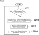
- the detection unit 50c may simply present the score. In this case, the operator or administrator looks at the score presented by the detection unit 50c and determines whether or not the tension is abnormal.
- steps S201 to S203 are the same processing as steps S101 to S103 described above, and therefore description thereof will be omitted.
- the detection unit 50c displays the score as a numerical value and a graph on the display unit 14 (S204).
- the degree of abnormality in the tension of the thread 93 being wound is detected while the thread winding machine 1 winds the thread 93.
- the degree of abnormality in the tension is detected in real time.
- data relating to the tension may also be stored while the thread 93 is being wound, and after the thread 93 is wound, the degree of abnormality in the tension may also be detected based on the stored data.
- the tension abnormality detection device 10 of the present embodiment detects the degree of abnormality in the tension of the thread 93 wound by the thread winding machine 1.
- the tension abnormality detection device 10 includes the tension sensor 13, the training unit 50b, the storage unit 50d, and the detection unit 50c.
- the tension sensor 13 detects the tension of the thread 93 wound by the thread winding machine 1.
- the training unit 50b constructs a conversion model that generates the same waveform based on a tension waveform with normal tension, by performing machine learning of the tension waveform with normal tension using an autoencoder.
- the storage unit 50d stores the conversion model constructed by the training unit 50b.
- the detection unit 50c generates an output tension waveform based on the input tension waveform obtained based on the tension detected by the tension sensor 13 and the conversion model that has learned the tension waveform, and detects the degree of abnormality in the tension of the thread 93 wound by the thread winding machine 1 based on the degree of similarity between the input tension waveform and the output tension waveform.
- the thread winding machine 1 winds the thread 93 onto the package 94 while causing the thread 93 to perform a traversing motion.
- the tension sensor 13 detects the tension by intermittently coming into contact with the thread 93 according to the traversing motion of the thread 93.
- the data detected by the tension sensor 13 intermittently coming into contact with the thread 93 includes not only the maximum value of the tension but also the change trend showing how the tension changes with time. For this reason, since the tension waveform includes many features, a model for accurately detecting the degree of abnormality in the tension of the thread 93 can be created.
- the detection unit 50c compares the input tension waveform and the output tension waveform to calculate a score that quantifies the degree of abnormality.
- a threshold is set in advance in the detection unit 50c, and the detection unit 50c determines that the tension is abnormal if the score is greater than or equal to the threshold, and determines that the tension is normal if the score is less than the threshold.
- the tension abnormality detection device 10 of the present embodiment includes the display unit 14, and the detection unit 50c performs control for creating a graph showing the change in the score over time and displaying the graph on the display unit 14.
- the detection unit 50c detects the degree of abnormality in the tension of the thread 93 being wound while the thread winding machine 1 winds the thread 93.
- the degree of abnormality in the tension can be detected in real time or at a timing close to real time. For this reason, for example, if the tension is abnormal, it is possible to perform processing such as interrupting the winding.
- the traverse device 21 of the above embodiment is of a cam drum type, it may have a different configuration as long as the traverse guide 23 can be moved back and forth in the winding width direction.
- a rotary traverse device using rotating blades or a belt-type traverse device in which a traverse guide is reciprocally driven by a belt can also be used.
- the present invention can also be applied to a false twisting machine or a rewinding machine.
- FIG. 9 is a diagram showing an example of the hardware configuration of the control device 50.
- the control device 50 includes the above-described storage unit 50d (see FIG. 3 ), a processor 101, a communication interface 104, a display interface 105, and an input interface 107. These components are connected to a bus 115. Examples of the storage unit 50d include a ROM (Read Only Memory) 102, a RAM 103, an auxiliary storage device 120, and the like.
- ROM Read Only Memory
- the processor 101 is constituted by, for example, at least one integrated circuit.
- An integrated circuit can be constituted by, for example, at least one CPU, at least one GPU (Graphics Processing Unit), at least one ASIC (Application Specific Integrated Circuit), at least one FPGA (Field Programmable Gate Array), or a combination thereof.
- the processor 101 controls the operation of the control device 50 by executing various programs.
- the processor 101 reads out programs to be executed from the auxiliary storage device 120 or the ROM 102 to the RAM 103 upon receiving execution instructions for various programs.
- the RAM 103 functions as a working memory and temporarily stores various types of data necessary for program execution.
- a LAN Local Area Network
- an antenna and the like are connected to the communication interface 104.
- the control device 50 exchanges data with an external device via the communication interface 104.
- the external device includes, for example, a server.
- the above-described display unit 14 (see FIG. 3 ) is connected to the display interface 105.
- the display interface 105 sends an image signal for displaying an image to display unit 14 according to a command from the processor 101 or the like.
- the display unit 14 is, for example, a liquid crystal display, an organic EL (Electro Luminescence) display, or other display. Note that the display unit 14 may also be formed in one piece with the control device 50 or may be formed separately from the control device 50.
- the input device 108 is connected to the input interface 107.
- the input device 108 is, for example, a mouse, keyboard, touch panel, or other device capable of accepting user operations. Note that the input device 108 may be formed in one piece with the control device 50 or may be formed separately from the control device 50.
- the auxiliary storage device 120 is, for example, a storage medium such as a hard disk, a flash memory, and an SSD.
- the auxiliary storage device 120 stores, for example, a training data set 122, the above-described conversion model 124, a training program 126, and a tension abnormality detection program 128.
- the storage location for these is not limited to the auxiliary storage device 120, and they may also be stored in a storage region of the processor 101 (e.g., cache memory, etc.), the ROM 102, the RAM 103, an external device (e.g., a server), or the like.
- the training program 126 is a program for generating the conversion model 124 using the training data set 122.
- the training program 126 may also be provided as part of any program, instead of as a standalone program. In this case, the training processing performed by the training program 126 is realized in cooperation with any program. Even if a program does not include some of these modules, the program does not deviate from the gist of the training program 126 according to the present embodiment.
- some or all of the functions provided by the training program 126 may also be realized by dedicated hardware.
- the control device 50 may be included in the form of a so-called cloud service in which at least one server executes some of the processing of the training program 126.
- the tension abnormality detection program 128 is a program for detecting abnormality in the tension of the thread wound by the thread winding machine 1, using the trained conversion model 124.
- the tension abnormality detection program 128 may also be provided as a part of any program, instead of as a standalone program. In this case, the abnormality detection processing performed by the tension abnormality detection program 128 is realized in cooperation with any program. Even if a program does not include some of these modules, the program does not deviate from the gist of the tension abnormality detection program 128 according to the present embodiment.
- some or all of the functions provided by the tension abnormality detection program 128 may also be realized by dedicated hardware.
- the control device 50 may be included in the form of a so-called cloud service in which at least one server executes some of the processing of the tension abnormality detection program 128.
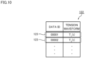
- FIG. 10 is a diagram showing an example of the training data set 122.
- the training data set 122 includes a plurality of pieces of training data 123.
- the number of pieces of training data 123 included in the training data set 122 is set as appropriate. As an example, the number of pieces of training data 123 is several tens to hundreds of thousands.
- a data ID (Identification) and a tension waveform with normal tension are associated with each other.
- the data ID is information for uniquely identifying the training data 123.
- the data ID is, for example, input by a user so as not to be redundant.
- the tension waveform defined by the training data 123 is a group of data in which tension detected by the above-described tension sensor 13 while the thread winding machine 1 winds the thread is arranged in chronological order. That is, in one piece of training data 123, a tension is associated with each time.
- the numbers of dimensions of the tension waveforms defined in the training data set 122 are equal to each other. Also, the training data set 122 is constituted by only the training data 123 for a normal tension waveform.
- FIG. 11 is a diagram showing an example of the functional configuration of the control device 50.
- control device 50 includes a training unit 50b and a detection unit 50c as functional configurations. These functional configurations will be described in order below.
- FIG. 12 is a diagram conceptually showing the training processing performed by the training unit 50b.
- the training unit 50b performs training processing using the above-described training data set 122 (see FIG. 10 ) to generate a conversion model 124 serving as an autoencoder.
- a machine learning algorithm adopted for the training processing is not particularly limited, and for example, a neural network such as deep learning or the like can be adopted. Training processing using a neural network will be described below.
- the conversion model 124 is constituted by an input layer X, an intermediate layer H, and an output layer Y
- the input layer X is configured to receive input of a normal tension waveform defined in the training data 123.
- the input layer X is composed of, for example, N units x 1 to x N (N is a natural number).
- the number of units constituting the input layer X is the same as the number of dimensions of the input tension waveform. For example, if the input tension waveform is N-dimensional data, the input layer X is constituted by N units.
- Each unit constituting the input layer X outputs input data to each unit of the first layer of the intermediate layer H.
- the intermediate layer H is constituted by one layer or a plurality of layers.
- the intermediate layer H is constituted by L layers (L is a natural number).
- Each layer of the intermediate layer H includes a plurality of units.
- the number of units in each layer of the intermediate layer H may be the same or different.
- the first layer of the intermediate layer H is constituted by Q units h A1 to h AQ (Q is a natural number).
- the final layer of the intermediate layer H is constituted by R units h L1 to h LR (R is a natural number).
- Each unit constituting each layer of the intermediate layer H is connected to each unit of the previous layer and each unit of the next layer.
- Each unit in each layer receives an output value from each unit in the previous layer, multiplies each output value by a weight, accumulates the multiplication results, adds (or subtracts) a predetermined bias to (or from) the accumulation result, inputs the addition result (or subtraction result) to a predetermined function (e.g., a sigmoid function), and outputs the output value of the function to each unit in the next layer.
- a predetermined function e.g., a sigmoid function
- the number of units constituting each layer of the intermediate layer H is smaller than the number of units constituting the input layer X.
- the number of dimensions of the tension waveform is compressed in the process of being transferred from the input layer X to the intermediate layer H.
- the output layer Y is configured to restore the tension waveform compressed in the intermediate layer H. More specifically, the output layer Y is constituted by the same number of units as the input layer X. As an example, if the input layer X is constituted by N units, the output layer Y is constituted by N units. In the example of FIG. 12 , the output layer Y is constituted by N units y 1 to y N . Hereinafter, the units y 1 to y N are also referred to as units y.
- Each of the units y is connected to each of the units h L1 to h LR in the final layer of the intermediate layer H.
- Each of the units y receives an output value from each of the units in the final layer of the intermediate layer H, multiplies each output value by a weight, accumulates the multiplication results, adds (or subtracts) a predetermined bias to (or from) the accumulation result, inputs the addition result (or subtraction result) to a predetermined function (e.g., a sigmoid function), and outputs the output result of the function as an output value.
- a predetermined function e.g., a sigmoid function
- the training unit 50b inputs a normal tension waveform T(t) defined in the first piece of training data 123 to the conversion model 124.
- the conversion model 124 compresses the tension waveform T(t) and restores the tension waveform T(t) to a tension waveform T '(t) of the same dimension.
- the training unit 50b calculates an error "Z" between the input tension waveform T(t) and the output tension waveform T'(t).
- the error "Z” is calculated based on the following formula (1).
- Z T t 1 ⁇ T ′ t 1 2 + ... + T t N ⁇ T ′ t N 2 / N
- the training unit 50b updates the internal parameters (e.g., weight and bias) of the conversion model 124 such that the error "Z" becomes smaller.
- the updating of the internal parameters is realized through, for example, error backpropagation.
- the training unit 50b repeatedly updates the internal parameters of the conversion model 124 for each piece of training data 123 included in the training data set 122.
- the conversion model 124 is trained to compress the normal tension waveform and then restore the normal tension waveform. That is, if a normal tension waveform is input, the conversion model 124 outputs a tension waveform similar to the normal tension waveform, and if an abnormal tension waveform is input, the conversion model 124 outputs a tension waveform different from the abnormal tension waveform.
- the conversion model 124 functions like a sort of filter that allows normal tension waveforms to pass but does not allow abnormal tension waveforms to pass.
- the training unit 50b does not need to use all of the training data 123 included in the training data set 122 for the training processing, and may use some of the training data 123 included in the training data set 122 to generate the conversion model 124.
- the rest of the training data 123 is used, for example, for evaluation of the conversion model 124 and the like.
- FIG. 13 is a diagram conceptually showing abnormality detection processing performed by the detection unit 50c.
- the detection unit 50c detects abnormality in the tension of the thread wound by the thread winding machine 1 based on the degree of similarity between the input tension waveform obtained from the tension sensor 13 and the output tension waveform obtained by inputting the input tension waveform to the conversion model 124.
- the detection unit 50c inputs the input tension waveform obtained from the tension sensor 13 to the conversion model 124 and acquires the output tension waveform from the conversion model 124.
- the acquisition destination of the conversion model 124 may be the storage unit 50d described above, or may be an external device. If a normal tension waveform is input, the conversion model 124 outputs a tension waveform similar to the normal tension waveform, and if an abnormal tension waveform is input, the conversion model 124 outputs a tension waveform different from the abnormal tension waveform.
- the detection unit 50c detects abnormality in the tension of the thread wound by the thread winding machine 1 based on the degree of similarity between the input tension waveform and the output tension waveform. Since the function of the detection unit 50c is as described above, detailed description of the function will not be repeated.
- the training unit 50b and the detection unit 50c were provided in the same thread winding machine 1. However, the training unit 50b and the detection unit 50c do not necessarily need to be provided in the same thread winding machine 1. As an example, the training unit 50b may also be provided in a different device.
- FIG. 14 is a diagram showing an example of the device configuration of an abnormality detection system 500 according to this modified example.
- the abnormality detection system 500 includes one or more thread winding machines 1 and one or more information processing devices 200.
- the abnormality detection system 500 is constituted by three thread winding machines 1A to 1C and one information processing device 200.
- the thread winding machines 1A to 1C and the information processing device 200 are connected to the same network NW and are configured to be able to communicate with each other.
- the thread winding machines 1 and the information processing device 200 may also be communicatively connected by wire or wirelessly.
- the information processing device 200 is a desktop personal computer, a notebook personal computer, a tablet terminal, or another information processing terminal.
- the training unit 50b is provided in the information processing device 200. Also, the detection unit 50c is provided in the thread winding machine 1C.
- the information processing device 200 collects the above-described training data 123 (see FIG. 10 ) from the thread winding machines 1 (e.g., the thread winding machines 1A and 1B) connected to the network NW.
- the training unit 50b of the information processing device 200 executes training processing using the training data 123 collected from all of the thread winding machines 1, and generates the above-described conversion model 124. Since the training function of the training unit 50b is as described above, description thereof will not be repeated.
- the information processing device 200 transmits the generated conversion model 124 to the thread winding machine 1 (e.g., the thread winding machine 1C).
- the detection unit 50c of the thread winding machine 1C uses the conversion model 124 to detect tension abnormalities generated in the thread winding machine 1C. Since the abnormality detection function of the detection unit 50c is as described above, description thereof will not be repeated.
- the tension abnormality detection device 10 determines whether or not abnormality of tension has occurred by inputting the input tension waveform obtained from the tension sensor 13 to the conversion model 124. On the other hand, the tension abnormality detection device 10 according to the present modified example further identifies the type of the tension abnormality that has occurred if it is determined that a tension abnormality has occurred. Note that other points such as the hardware configuration of the tension abnormality detection device 10 are as described above, and therefore description thereof will not be repeated.
- FIG. 15 is a diagram showing an example of the training data set 132.
- the training data set 132 includes a plurality of pieces of training data 133.
- the number of pieces of training data 133 included in the training data set 132 is set as appropriate. As an example, the number of pieces of training data 133 is several tens to several hundreds of thousands.
- a data ID (Identification), a tension waveform with abnormal tension, and a type of abnormal tension are associated.
- a data ID is information for uniquely identifying the training data 133.
- the data ID is input by the user, for example, so as not to be redundant.
- the tension waveform defined in the training data 133 is a data group in which the tension detected by the above-described tension sensor 13 while the thread winding machine 1 winds the thread is arranged chronologically.
- the numbers of the dimensions of the tension waveforms defined in the training data set 132 are equal to each other.
- each tension waveform is associated with an abnormality type as a label.
- the abnormality type is input by the user via, for example, the input device 108 described above, or the like.
- FIG. 16 is a diagram showing an example of the functional configuration of the control device 50.
- the control device 50 includes a training unit 50b, a detection unit 50c, a training unit 50e, and an identification unit 50f as functional configurations.
- the control device 50 shown in FIG. 16 is different from the control device 50 shown in FIG. 11 in that it further includes the training unit 50e and the identification unit 50f. Since the functional descriptions of the training unit 50b and the detection unit 50c are as described above, the description thereof will not be repeated.
- the functions of the training unit 50e and the identification unit 50f will be described in order below.
- the training unit 50b the detection unit 50c, the training unit 50e, and the identification unit 50f in the control device 50.
- at least one of the training unit 50b and the training unit 50e may be provided in the information processing device 200 described above.
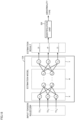
- FIG. 17 is a diagram conceptually showing training processing performed by the training unit 50e.
- the training unit 50e executes training processing using the above-described training data set 132 (see FIG. 15 ), and generates an estimation model 134 for identifying a tension abnormality.
- a machine learning algorithm employed for training processing is not particularly limited, and for example, various machine learning algorithms, such as a neural network such as deep learning, a support vector machine, or a decision tree system, can be employed thereas. Hereinafter, training processing using deep learning will be described.
- the estimation model 134 is constituted by an input layer X, an intermediate layer H, and an output layer Y
- the input layer X is configured to receive input of an abnormal tension waveform defined in the training data 133.
- the input layer X is constituted by, for example, N units x 1 to x N (N is a natural number).
- the number of units constituting the input layer X is the same as the number of dimensions of the input tension waveform. For example, if the input detention waveform is data of N dimensions, the input layer X is constituted by N units.
- Each unit constituting the input layer X outputs input data to each unit of the first layer of the intermediate layer H.
- the intermediate layer H is constituted by one layer or a plurality of layers.
- the intermediate layer H is constituted by L layers (L is a natural number).
- Each layer of the intermediate layer H includes a plurality of units.
- the number of units in each layer of the intermediate layer H may be the same or different.
- the first layer of the intermediate layer H is constituted by Q units h A1 to h AQ (Q is a natural number).
- the final layer of the intermediate layer H is constituted by R units h L1 to h LR (R is a natural number).
- Each unit constituting each layer of the intermediate layer H is connected to each unit of the previous layer and each unit of the next layer.
- Each unit in each layer receives an output value from each unit in the previous layer, multiplies the output value by a weight, accumulates the multiplication results, adds (or subtracts) a predetermined bias to (or from) the accumulation result, inputs the addition result (or subtraction result) to a predetermined function (e.g., a sigmoid function), and outputs the output value of the function to each unit of the next layer.
- a predetermined function e.g., a sigmoid function
- the output layer Y outputs an estimation result corresponding to the input tension waveform.
- the output layer Y is constituted by units y, to y 3 , for example.
- the units y, to y 3 are also referred to as units y.
- Each of the units y is connected to the units h L1 to h LR in the final layer of the intermediate layer H.
- Each unit y receives an output value from each unit of the final layer of the intermediate layer H, multiplies each output value by a weight, integrates the multiplication results, adds (or subtracts) a predetermined bias to (or from) the integration result, inputs the addition result (or subtraction result) to a predetermined function (e.g., a sigmoid function), and outputs the output result of the function as an output value.
- a predetermined function e.g., a sigmoid function
- the number of units constituting the output layer Y is determined according to the number of types of tension abnormalities defined in the training data 133.
- the number of units constituting the output layer Y is three, namely the units y 1 to y 3 .
- the unit y 1 is configured to output a score "sa” that indicates the likelihood that the tension abnormality "A” has occurred.
- the unit y 2 is configured to output a score "sb” indicating the likelihood that the tension abnormality "B” has occurred.
- the unit y 3 is configured to output a score "sc” indicating the likelihood that the tension abnormality "C” has occurred.
- the estimation model 134 is configured to output a plurality of scores, but one estimation model may also be configured to output one score.
- a first estimation model may be configured to output a score "sa” for an abnormality type "A”
- a second estimation model may be configured to output a score "sb” for an abnormality type "B”
- a third estimation model may be configured to output a score "sc” for an abnormality type "C”.
- the training unit 50e inputs a tension waveform T(t) defined in the first piece of training data 133 to the estimation model 134. Next, the training unit 50e obtains the estimation results "sa” to “sc” output from the estimation model 134 and correct answer scores "sa"' to "sc′′′ corresponding to the abnormality type associated with the first piece of training data 133.
- the training unit 50e calculates an error "Z” between output results “sa” to “sc” of the estimation model 134 and the correct answer scores "sa′′′ to “sc”'.
- the error "Z” is calculated, for example, based on the following formula (2).
- Z sa ⁇ sa ′ 2 + sb ⁇ sb ′ 2 + sc ⁇ sc ′ 2 / 3
- the training unit 50e updates the various parameters (for example, weights and biases) included in the estimation model 134 such that the error "Z" becomes smaller. Updating of the parameters is realized, for example, through the error backpropagation method.
- the training unit 50e repeatedly updates the internal parameters of the estimation model 134 for each piece of training data 133 included in the training data set 132. As a result, the estimation model 134 outputs more accurate estimation results as training progresses.
- the training unit 50e does not need to use all of the training data 133 included in training data set 132 for training processing, and may use some of the training data 133 included in the training data set 132 to generate the estimation model 134.
- the remaining training data 133 is used, for example, for evaluation of the estimation model 134.
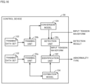
- FIG. 18 is a diagram conceptually showing processing for identifying an abnormality type, performed by the identification unit 50f.
- the identification unit 50f acquires the estimation model 134 generated by the training unit 50e.
- the acquisition destination of the estimation model 134 may be the storage unit 50d described above, or may be an external device. If a tension abnormality is detected by the above-described detection unit 50c, the identification unit 50f identifies the type of tension abnormality that has occurred, based on the input tension waveform used for detecting the tension abnormality and the estimation model 134.
- the identification unit 50f inputs, to the estimation model 134, an input tension waveform indicating an abnormality.
- the estimation model 134 outputs a score indicating the likelihood that a tension abnormality has occurred, to the abnormality type. For example, as the estimation result, the estimation model 134 outputs a score "sa” indicating the likelihood that a tension abnormality "A” has occurred, a score “sb” indicating the likelihood that a tension abnormality "B” has occurred, and a score "sc” indicating the likelihood that a tension abnormality "C” has occurred.
- the identification unit 50f identifies the type of tension abnormality that has occurred based on the scores "sa" to "sc". As an example, if any one of the scores “sa” to “sc" exceeds a predetermined threshold, the identification unit 50f outputs, as the identification result, the tension abnormality corresponding to the maximum score among the scores "sa” to "sc". On the other hand, if none of the scores "sa” to "sc" exceed the predetermined threshold, the identification unit 50f outputs that an unknown tension abnormality has occurred.
- the predetermined threshold may be pre-set or set as appropriate by the user.
- the output mode of the identification result by the identification unit 50f is not particularly limited.
- the identification unit 50f outputs a warning including the type of tension abnormality that has occurred.
- the warning may be displayed as a message on the display unit 14 described above, may be output by voice, or may be stored in the storage unit 50d as a log.
- this embodiment includes the following disclosures.
- a tension abnormality detection device having the following configuration. That is, the tension abnormality detection device detects a degree of abnormality in tension of a thread wound by a thread winding machine.
- the tension abnormality detection device includes a tension sensor, a training unit, a storage unit, and a detection unit.
- the tension sensor detects the tension of the thread wound by the thread winding machine.
- the training unit that performs machine learning on a tension waveform with normal tension using an autoencoder to construct a conversion model that, based on a waveform with normal tension, generates the same waveform.
- the storage unit stores the conversion model constructed by the training unit.
- the detection unit generates an output tension waveform based on the conversion model and the input tension waveform based on the tension detected by the tension sensor, and detects a degree of abnormality in the tension of the thread wound by the thread winding machine based on a degree of similarity between the input tension waveform and the output tension waveform.
- the tension abnormality detection device has the following configuration. That is, the thread winding machine winds the thread onto the bobbin while causing the thread to perform a traversing motion.
- the tension sensor detects tension by intermittently coming into contact with the thread according to the traversing motion of the thread.
- the data detected by the tension sensor intermittently coming into contact with the thread includes not only the maximum value of the tension but also the change trend indicating how the tension changes with time. For this reason, since the tension waveform includes a large number of features, it is possible to create a model for accurately detecting the degree of abnormality in the tension of the thread.
- the detection unit calculates a score quantifying the degree of abnormality by comparing the input tension waveform and the output tension waveform.
- a threshold is set in advance in the detection unit, and the detection unit determines that the tension is abnormal if the score is greater than or equal to the threshold, and determines that the tension is normal if the score is less than the threshold.
- the tension abnormality detection device further includes a display unit, and the detection unit performs control for creating a graph showing the change in the score over time and displaying the graph on the display unit.
- the training unit and the detection unit detect the degree of abnormality in the tension of the thread being wound while the thread winding machine winds the thread.
- the degree of abnormality in the tension can be detected in real time or at a timing close to real time. For this reason, for example, if the tension is abnormal, it is possible to perform processing such as interrupting the winding.
Landscapes
- Engineering & Computer Science (AREA)
- Quality & Reliability (AREA)
- Mechanical Engineering (AREA)
- Textile Engineering (AREA)
- Filamentary Materials, Packages, And Safety Devices Therefor (AREA)
Abstract
Description
- The present disclosure relates to a tension abnormality detection device, a tension abnormality detection method, and a tension abnormality detection program.
-
JP 2002-302824A Patent Document 1, the obtained average value of the tension is compared with the upper and lower thresholds therefor, and it is detected whether or not there is an abnormality by comparing the obtained standard deviation of the tension and the upper threshold. -
JP 2002-302824A - In the method of
Patent Document 1, abnormalities are uniformly detected based on the average value of the tension and the standard deviation of the tension. However, since there are various patterns of abnormalities in tension, it is not easy to accurately detect various abnormalities in tension based on only the average value of the tension and the standard deviation of the tension. - The present disclosure has been made in view of the above circumstances, and a main purpose thereof is to provide a tension abnormality detection device, a tension abnormality detection method, and a tension abnormality detection program, according to which it is possible to accurately detect various abnormalities related to tension of a thread wound by a thread winding machine.
- In one example of the present disclosure, a tension abnormality detection device is provided. The tension abnormality detection device includes a control device and a tension sensor for detecting tension of a thread wound by a thread winding machine. The control device executes processing for acquiring an autoencoder trained to compress a normal tension waveform and then restore the normal tension waveform, and processing for detecting an abnormality in the tension of the thread wound by the thread winding machine, based on a degree of similarity between an input tension waveform obtained from the tension sensor and an output tension waveform obtained by inputting the input tension waveform to the autoencoder.
- In this tension abnormality detection device, an autoencoder trained based on a tension waveform with normal tension is used to detect an abnormality in the tension of a thread. For this reason, various abnormalities that deviate from normal tension can be detected. For example, abnormalities that cannot be detected with only the magnitude of the tension or the degree of change in the tension are detected.
- In one example of the present disclosure, the control device further executes training processing for generating the autoencoder using a normal tension waveform.
- As a result, the training processing is executed by the tension abnormality detection device. Due to the tension abnormality detection device having a learning function, the tension abnormality detection device can generate the autoencoder by itself.
- In one example of the present disclosure, the thread winding machine winds thread on a bobbin while causing the thread to perform a traversing motion, and the tension sensor is configured to detect tension by intermittently coming into contact with the thread according to the traversing motion of the thread.
- As a result, the data detected by the tension sensor that intermittently comes into contact with the thread includes not only the maximum value of the tension but also a change trend indicating how the tension changes over time. As a result, the tension waveform includes a large number of features, and therefore an autoencoder for accurately detecting the degree of abnormality in the tension of the thread is generated.
- In one example of the present disclosure, in the detecting processing, abnormality of tension is detected if the degree of similarity is greater than or equal to a predetermined threshold. Normality of tension is detected if the degree of similarity is less than the predetermined threshold.
- As a result, the tension abnormality detection device can detect a tension abnormality according to the threshold.
- In one example of the present disclosure, the tension abnormality detection device further includes a display unit. The control device further executes processing for creating a graph showing change over time in the degree of similarity and displaying the graph on the display unit.
- As a result, for example, an administrator or an operator can intuitively grasp the degree of abnormality in the tension.
- In one example of the present disclosure, the control device executes the detecting processing while the thread winding machine winds the thread.
- As a result, the tension abnormality detection device can detect the degree of abnormality in the tension in real time or at a timing close to real time. For this reason, if the tension is abnormal, the administrator or operator can also perform processing such as interrupting the winding.
- In one example of the present disclosure, the control device further executes processing for acquiring an estimation model trained to receive input of a tension waveform and output a type of the abnormality, and processing for, if abnormality of tension is detected in the detecting processing, identifying the type of the abnormality based on the input tension waveform and the estimation model.
- As a result, the tension abnormality detection device can not only detect the occurrence of a tension abnormality, but also identify the type of the tension abnormality that has occurred.
- In another example of the present disclosure, a tension abnormality detection method to be performed by a tension abnormality detection device is provided. The tension abnormality detection device includes a tension sensor for detecting tension of a thread wound by the thread winding machine. The tension abnormality detection method includes a step of acquiring an autoencoder trained to compress a normal tension waveform and then restore the normal tension waveform; and a step of detecting abnormality in the tension of the thread wound by the thread winding machine, based on a degree of similarity between an input tension waveform obtained from the tension sensor and an output tension waveform obtained by inputting the input tension waveform to the autoencoder.
- In this tension abnormality detection method, an autoencoder trained based on a tension waveform with normal tension is used to detect abnormality in the tension of a thread. For this reason, various abnormalities that deviate from normal tension can be detected. For example, abnormalities that cannot be detected with only the magnitude of the tension or degree of change in the tension are detected.
- Another example of the present disclosure provides a tension abnormality detection program to be executed by a tension abnormality detection device. The tension abnormality detection device includes a tension sensor for detecting tension of a thread wound by a thread winding machine. The tension abnormality detection program causes the tension abnormality detection device to execute: a step of acquiring an autoencoder trained to compress a normal tension waveform and then restore the normal tension waveform; and a step of detecting abnormality in the tension of the thread wound by the thread winding machine based on a degree of similarity between an input tension waveform obtained from the tension sensor and an output tension waveform obtained by inputting the input tension waveform to the autoencoder.
- In this tension abnormality detection program, an autoencoder trained based on a tension waveform with normal tension is used to detect abnormality in the tension of a thread. For this reason, various abnormalities that deviate from normal tension can be detected. For example, abnormalities that cannot be detected with only the magnitude of the tension or the degree of change in the tension are detected.
-
-
FIG. 1 is a front view of a thread winding machine according to one embodiment. -
FIG. 2 is a diagram showing a side view of the thread winding machine. -
FIG. 3 is a diagram showing a block diagram of the thread winding machine. -
FIG. 4 is a diagram showing a method for obtaining an output tension waveform from an input tension waveform using a conversion model. -
FIG. 5 is a graph showing an input tension waveform, an output tension waveform, and a score when there is no tension abnormality. -
FIG. 6 is a graph showing an input tension waveform, an output tension waveform, and a score when there is a tension abnormality. -
FIG. 7 is a diagram showing a flowchart for determining whether or not there is a tension abnormality. -
FIG. 8 is a diagram showing a flowchart showing processing for causing an operator to determine whether or not there is a tension abnormality. -
FIG. 9 is a diagram showing an example of a hardware configuration of a control device. -
FIG. 10 is a diagram showing an example of a training data set. -
FIG. 11 is a diagram showing an example of a functional configuration of a control device. -
FIG. 12 is a diagram conceptually showing training processing performed by a training unit. -
FIG. 13 is a diagram conceptually showing abnormality detection processing performed by a detection unit. -
FIG. 14 is a diagram showing an example of a device configuration of an abnormality detection system. -
FIG. 15 is a diagram showing an example of a training data set. -
FIG. 16 is a diagram showing an example of a functional configuration of a control device. -
FIG. 17 is a diagram conceptually showing training processing performed by a training unit. -
FIG. 18 is a diagram conceptually showing processing for identifying an abnormality type, performed by an identification unit. - Hereinafter, each embodiment according to the present invention will be described with reference to the drawings. In the following description, identical parts and constituent elements are denoted by identical reference numerals. Their names and functions are also the same. Accordingly, detailed description thereof will not be repeated. Note that each embodiment and modified example described below may also be selectively combined with each other as appropriate.
- Next, an embodiment of the present disclosure will be described with reference to the drawings.
FIG. 1 is a front view of athread winding machine 1 according to an embodiment of the present disclosure.FIG. 2 is a side view of thethread winding machine 1.FIG. 3 is a block diagram of thethread winding machine 1. In the following description, upstream or downstream in the travel direction of the thread is simply referred to as upstream or downstream in some cases. - A spinning machine (not shown) is arranged upstream of the
thread winding machine 1 shown inFIG. 1 . The spinning machine produces athread 93 and supplies thethread 93 to thethread winding machine 1. Thethread winding machine 1 winds thethread 93 around abobbin 91 to manufacture apackage 94. As shown inFIG. 1 , thepackage 94 is formed by winding thethread 93 on thebobbin 91 at an upper winding position to form a thread layer. On the other hand, thethread 93 is not wound on thebobbin 91 at the lower standby position. - The
thread 93 is a highly stretchable synthetic thread such as nylon or polyester. More specifically, thethread 93 is, for example, FDY (Fully Draw Yarn) or POY (Partially Oriented Yarn). However, the types of thethread 93 are not limited to these, and a tensionabnormality detection device 10, which will be described later, can be applied also to threads other than those described above. - Also, as shown in
FIG. 2 , in the present embodiment, a plurality ofthreads 93 arranged side by side in the axial direction of the first bobbin holder 41 (second bobbin holder 42) are supplied from athread feed roller 100 to thethread winding machine 1 from the spinning machine. Also, a plurality ofbobbins 91 are arranged side by side in the axial direction of the first bobbin holder 41 (second bobbin holder 42). Thethread winding machine 1 winds a plurality ofthreads 93 onto thebobbins 91 to manufacture a plurality ofpackages 94. - Details of the
thread winding machine 1 will be described below. As shown inFIG. 1 , thethread winding machine 1 includes aframe 11, asupport point guide 12, afirst housing 20, asecond housing 30, and a turret plate (bobbin holder moving mechanism) 40. - The
frame 11 is a member that holds each part of thethread winding machine 1. Thefirst housing 20 and thesecond housing 30 are mounted on theframe 11. Thefirst housing 20 and thesecond housing 30 can move up and down with respect to theframe 11. - The
support point guide 12 is arranged on theframe 11. Thesupport point guide 12 guides thethread 93 supplied to thethread winding machine 1 from the spinning machine. Specifically, thesupport point guide 12 has a wall portion that comes into contact with thethread 93, and restricts the position of thethread 93 such that thethread 93 does not deviate from the thread path. - A
traverse device 21 is attached to thefirst housing 20. Thetraverse device 21 causes thethread 93 fed downstream to perform a traversing motion by moving back and forth on the winding width of thepackage 94 along the axial direction of a later-describedfirst bobbin holder 41 while a later-describedtraverse guide 23 engages with thethread 93. A thread layer is formed on thebobbin 91 or thepackage 94 by this traversing motion of thethread 93. As shown inFIG. 3 , thetraverse device 21 includes atraverse cam 22 and atraverse guide 23. - The
traverse cam 22 is a roller-shaped member arranged parallel to thebobbin 91 or thepackage 94. A spiral cam groove is formed on the outer peripheral surface of thetraverse cam 22. Thetraverse cam 22 is rotationally driven by atraverse motor 51. - The
traverse motor 51 is controlled by a later-describedcontrol device 50. Thetraverse guide 23 is a part that engages with thethread 93. The leading end of thetraverse guide 23 has, for example, a substantially U-shaped guide portion, which engages with thethread 93 so as to sandwich thethread 93 in the winding width direction. The base end of thetraverse guide 23 is located in the cam groove of thetraverse cam 22. With this configuration, by rotationally driving thetraverse cam 22, thetraverse guide 23 can be moved back and forth in the winding width direction with thesupport point guide 12 serving as a support point. - A
contact roller 31 is rotatably mounted on thesecond housing 30. When thethread 93 is wound, thecontact roller 31 is driven to rotate while in contact with the thread layer of thepackage 94 with a predetermined pressure, whereby thethread 93 from thetraverse guide 23 is fed to the thread layer of thepackage 94 and the thread layer shape of thepackage 94 is adjusted. Note that thecontact roller 31 may be rotationally driven using a drive unit such as a motor - An
operation panel 32 is provided on thesecond housing 30. Theoperation panel 32 is a device operated by an operator. The operator gives instructions to thethread winding machine 1 by operating theoperation panel 32. Instructions given by the operator include, for example, starting winding, stopping winding, and changing winding conditions. - A
tension sensor 13 is provided on the thread path from the spinning machine to thetraverse device 21. Specifically, thetension sensor 13 is provided downstream of thesupport point guide 12 and upstream of thetraverse device 21 in the travel direction of thethread 93. Accordingly, thetension sensor 13 detects the tension of thethread 93 that is moved back and forth by thetraverse device 21. Thetension sensor 13 has a pair of arm portions (not shown). One arm portion comes into contact with thethread 93 at one end of the traversing motion. The other arm portion comes into contact with thethread 93 at the other end of the traversing motion. That is, thetension sensor 13 intermittently comes into contact with thethread 93 performing a traversing motion. Also, a strain gauge is provided on the arm portion, and the strain of the arm portion detected by the strain gauge correlates with the tension of thethread 93. Accordingly, the tension of thethread 93 can be obtained based on the signal output by the strain gauge. A signal indicating the value of the tension detected by thetension sensor 13 is output to thecontrol device 50, which will be described later. Also, the signal output by thetension sensor 13 includes a tension waveform that indicates change in the tension over time. - Note that the
tension sensor 13 described above is merely an example, and atension sensor 13 having a configuration different from that of the present embodiment may also be used. For example, thetension sensor 13 is not limited to intermittently coming into contact with thethread 93, and may be configured to continuously be in contact with thethread 93. Also, thetension sensor 13 may detect tension using a spring or a piezoelectric element instead of the strain gauge. - As shown in
FIG. 3 , thethread winding machine 1 has adisplay unit 14. Thedisplay unit 14 is a display capable of displaying information. Thedisplay unit 14 is, for example, a liquid crystal display or an organic EL display. Thedisplay unit 14 displays an image output by thecontrol device 50, which will be described later, on a screen. - The
turret plate 40 is a disk-shaped member. Theturret plate 40 is rotatably mounted on theframe 11. Theturret plate 40 can rotate using a normal line passing through the center of the disk as a rotation axis. Theturret plate 40 is rotationally driven by aturret motor 53 shown inFIG. 3 . Theturret motor 53 is controlled by thecontrol device 50, which will be described later. - A
first bobbin holder 41 and asecond bobbin holder 42 are respectively provided at two locations on theturret plate 40 that oppose each other across the center of the disk. A plurality ofbobbins 91 can be mounted side by side in the axial direction of thefirst bobbin holder 41 on thefirst bobbin holder 41. The plurality ofbobbins 91 can be mounted side by side in the axial direction of thesecond bobbin holder 42 on thesecond bobbin holder 42. The positions of thefirst bobbin holder 41 and thesecond bobbin holder 42 can be changed by rotating theturret plate 40. Note that another device may be used instead of theturret plate 40, as long as the positions of thefirst bobbin holder 41 and thesecond bobbin holder 42 can be changed. - The
first bobbin holder 41 is rotatable with respect to theturret plate 40 using the axis position of thefirst bobbin holder 41 as the center of rotation. Thefirst bobbin holder 41 is rotationally driven by a firstbobbin holder motor 54 shown inFIG. 3 . Similarly, thesecond bobbin holder 42 is rotatable with respect to theturret plate 40 using the axis position of thesecond bobbin holder 42 as the center of rotation. Thesecond bobbin holder 42 is rotationally driven by a secondbobbin holder motor 55 shown inFIG. 3 . The firstbobbin holder motor 54 and the secondbobbin holder motor 55 are controlled by thecontrol device 50, which will be described later. - Hereinafter, the
first bobbin holder 41 and thesecond bobbin holder 42 are collectively referred to asbobbin holders FIG. 1 shows a state in which thebobbin holders bobbin holders bobbin holders thread winding machine 1 produces thepackage 94 by winding thethread 93 around thebobbins 91 of thebobbin holders - Also, if the
packages 94 of thefirst bobbin holder 41 are fully wound by winding a predetermined amount of thethread 93, the positions of thefirst bobbin holder 41 and thesecond bobbin holder 42 are switched by rotating theturret plate 40. Thereafter, thepackages 94 of thefirst bobbin holder 41 that are fully wound and are at the standby position are collected, and thethread 93 is wound onto thebobbins 91 of thesecond bobbin holder 42 that are at the winding position.New bobbins 91 are mounted on thefirst bobbin holder 41 from which thepackages 94 have been collected. - The
control device 50 includes acontrol unit 50a, atraining unit 50b, adetection unit 50c, and astorage unit 50d. Specifically, thecontrol device 50 is configured as a known computer, and includes a CPU (Central Processing Unit), RAM (Random Access Memory), SSD (Solid State Drive), and the like. A CPU is a type of processor. Programs and data for controlling thethread winding machine 1 are stored in advance in the SSD. Also, the SSD stores tension input from thetension sensor 13 in chronological order. Due to the CPU reading out the program to the RAM and executing the program, thecontrol device 50 can operate as thecontrol unit 50a, thetraining unit 50b, and thedetection unit 50c. Also, the SSD corresponds to thestorage unit 50d. Note that an HDD (Hard Disk Drive) or flash memory may be used instead of the SSD. Alternatively, a storage that is provided outside of thecontrol device 50 and can communicate with thecontrol device 50 may also be used as the storage unit. - The
control unit 50a performs overall control of thecontrol device 50. Thecontrol unit 50a processes the data input to thecontrol device 50 from the outside or data stored in thestorage unit 50d. Thecontrol unit 50a stores the data obtained through this processing in thestorage unit 50d or outputs the data to the outside of thecontrol device 50. Thetraining unit 50b performs processing for constructing a conversion model using machine learning. Details of the conversion model constructed by thetraining unit 50b will be described later. Thedetection unit 50c performs detection processing for detecting an abnormality based on data externally input to thecontrol device 50 and the conversion model constructed by thetraining unit 50b and stored in thestorage unit 50d. Thestorage unit 50d stores data according to the processing of thecontrol unit 50a. -
FIG. 3 shows the tensionabnormality detection device 10. The tensionabnormality detection device 10 detects the degree of abnormality in the tension of thethread 93 wound by thethread winding machine 1. The tensionabnormality detection device 10 includes acontrol device 50, atension sensor 13, and adisplay unit 14. Thecontrol device 50 performs the following processing as a component of the tensionabnormality detection device 10. - That is, the
control unit 50a outputs data to thetraining unit 50b and thedetection unit 50c for processing. Thecontrol unit 50a causes thestorage unit 50d to store data obtained by thetraining unit 50b and thedetection unit 50c performing processing. Also, thecontrol unit 50a stores the tension waveform detected by thetension sensor 13 in thestorage unit 50d. Note that atraverse motor 51, aturret motor 53, a firstbobbin holder motor 54, and a secondbobbin holder motor 55 are further included as objects to be controlled by thecontrol unit 50a. Thetraining unit 50b constructs a conversion model by performing machine learning based on a tension waveform stored in thestorage unit 50d or a tension waveform based on the detection value of the tension input from thetension sensor 13. Thedetection unit 50c detects a degree of abnormality in the tension of thethread 93 wound by thethread winding machine 1 and determines whether or not there is an abnormality based on data input to thecontrol device 50 from the outside (specifically, tension detected by the tension sensor 13) and a conversion model constructed by thetraining unit 50b and stored in thestorage unit 50d. The determination result obtained through the processing of thedetection unit 50c is output to the outside or stored in thestorage unit 50d by thecontrol unit 50a. Thestorage unit 50d stores data obtained through the processing of thecontrol unit 50a, thetraining unit 50b, and thedetection unit 50c, as described above. - The conversion model is an autoencoder, and is constructed by the
training unit 50b performing the following machine learning. First, the operator or administrator instructs thetraining unit 50b to start machine learning. Upon receiving this instruction, thetraining unit 50b requests thetension sensor 13 to transmit the detection value of the tension. Thetension sensor 13 outputs the detection value of the tension to thetraining unit 50b. Thetraining unit 50b buffers the detection value of the tension input from thetension sensor 13. The processing for acquiring and buffering the detection value of the tension by thetraining unit 50b is performed repeatedly. Thereafter, thetraining unit 50b performs machine learning on the buffered detection value of the tension to construct a conversion model. Note that the detection value of the tension output by thetension sensor 13 may be stored in thestorage unit 50d based on a request from thetraining unit 50b, and thetraining unit 50b may construct the conversion model by performing machine learning based on the content stored in thestorage unit 50d. The conversion model constructed by thetraining unit 50b is stored in thestorage unit 50d and set in thedetection unit 50c. This completes the machine learning. - Since the
tension sensor 13 of this embodiment is configured to intermittently come into contact with thethread 93, the tension waveform is triangular. Also, training data for creating a conversion model is a tension waveform with normal tension. Only tension waveforms with normal tension are used to create the conversion model, and tension waveforms with abnormal tension are not used. Since the frequency of occurrence of an abnormality in tension is generally low, it is easy to prepare a tension waveform with normal tension. - A conversion model is constructed by performing unsupervised learning using the above training data for an input layer, an intermediate layer, and an output layer in a multi-layer neural network. The learning performed here is deep learning, and since feature amounts are specified through learning, input of feature amounts is unnecessary. By setting a tension waveform with normal tension for the conversion model constructed by performing this learning, important feature amounts included in the tension waveform are extracted and compressed into an intermediate layer (hidden layer), and thereafter a restored tension waveform is generated based on the feature amounts. That is, the conversion model is used such that if the input tension waveform is a tension waveform with normal tension, the output tension waveform will generate a tension waveform similar to the input tension waveform. Note that the method for constructing a conversion model of the present embodiment is an example, and another method can also be used.
- As shown in
FIG. 4 , the conversion model is used by thedetection unit 50c. Specifically, thedetection unit 50c generates the output tension waveform based on the input tension waveform and the conversion model. Here, if the input tension waveform is a tension waveform with normal tension, thedetection unit 50c generates a tension waveform similar to the input tension waveform as the output tension waveform. Then, if the input tension waveform is an abnormal tension waveform, thedetection unit 50c generates a tension waveform different from the input tension waveform as the output tension waveform. -
FIG. 5 shows a tension waveform (input tension waveform) in which no tension abnormality occurs, and an output tension waveform generated by thedetection unit 50c based on the input tension waveform and the conversion model. Since the input tension waveform does not include a tension abnormality, the input tension waveform and the output tension waveform are substantially the same and have a high degree of similarity. -
FIG. 6 shows a tension waveform (input tension waveform) in which a tension abnormality occurs, and an output tension waveform generated by thedetection unit 50c based on the input tension waveform and the conversion model. Since the input tension waveform includes a tension abnormality, the degree of similarity between the input tension waveform and the output tension waveform is low in the time span when the tension abnormality occurs (the time span indicated by the dashed-line ellipse). - The
detection unit 50c compares the input tension waveform and the output tension waveform, and detects the degree of abnormality in the tension of thethread 93 based on the degree of similarity between the input tension waveform and the output tension waveform. Various methods for obtaining a degree of correlation between two pieces of data can be used to compare the input tension waveform and the output tension waveform. In this embodiment, the Mahalanobis distance is used. The Mahalanobis distance is a virtual distance calculated with consideration given to the correlative relationship, and the distance decreases when the correlation is high. Note that since the Mahalanobis distance is publicly known, detailed description thereof is omitted. Thedetection unit 50c calculates the Mahalanobis distance for each time span based on the input tension waveform and the output tension waveform. Here, the correlation between the input tension waveform and the output tension waveform indicates the degree of similarity of the waveforms. That is, if the tension is normal, the degree of similarity between the input tension waveform and the output tension waveform is high, and the Mahalanobis distance is small. If the tension is abnormal, the degree of similarity between the input tension waveform and the output tension waveform decreases, and the Mahalanobis distance increases. Therefore, an increase in the Mahalanobis distance indicates a degree of abnormality in the tension. The Mahalanobis distance is hereinafter referred to as a score. As mentioned above, values other than the Mahalanobis distance can also be used as scores. - The score is low because the input tension waveform in
FIG. 5 includes no tension abnormality. On the other hand, since the input tension waveform inFIG. 6 includes a tension abnormality, the score becomes high in the time span when the tension abnormality is included. By using the score, the degree of similarity between the input tension waveform and the output tension waveform, or in other words, the degree of abnormality in the tension, can be indicated by a specific numerical value. - Also, as shown in
FIGS. 5 and6 , a threshold may be set for the score. In this case, the threshold is set in thedetection unit 50c in advance. The threshold can be determined experimentally or empirically. Thedetection unit 50c may determine whether or not the tension is abnormal based on whether the score is greater than or equal to the threshold or less than the threshold. - In the example shown in
FIG. 6 , the tension is very large during the time span when the tension abnormality occurs, compared to other time spans. This is an example of a tension abnormality, and there are various types of tension abnormalities. Depending on the type of tension abnormality, the mode in which the tension changes may differ from those of other time spans. With this type of tension abnormality, the tension abnormality cannot be determined using only the magnitude of the tension. However, by using the method of the present embodiment, even with this type of tension abnormality, the score is high, and therefore this type of tension abnormality can be detected. - Next, a flow of processing performed by the tension
abnormality detection device 10 will be described mainly with reference toFIG. 7 . - The operator or administrator sets the above-described threshold in the
detection unit 50c in advance. Thereafter, the operator or administrator instructs thedetection unit 50c to detect abnormality in the tension. Also, thedetection unit 50c determines whether or not the tension abnormality detection timing has been reached (S101), and if there is an instruction from an operator or administrator, thedetection unit 50c determines that the detection timing has been reached. - Next, the
detection unit 50c generates an output tension waveform (S 102). Specifically, thedetection unit 50c requests thetension sensor 13 to transmit the detection value of the tension if it is determined that the detection timing has been reached. Thetension sensor 13 outputs the detection value of the tension to thedetection unit 50c. Thedetection unit 50c buffers the detection value of the tension input from thetension sensor 13. Thereafter, thedetection unit 50c generates an output tension waveform based on the input tension waveform based on the buffered detection value of the tension and the conversion model stored in thestorage unit 50d. Next, thedetection unit 50c compares the input tension waveform and the output tension waveform, and calculates the score as described above (S103). - Next, the
detection unit 50c determines whether or not the score is greater than or equal to the threshold (S104). If thedetection unit 50c determines that the score is greater than or equal to the threshold, thedetection unit 50c determines that the tension is abnormal (S105). In this case, thecontrol unit 50a or thedetection unit 50c may also store the time when the tension was abnormal, or the like. Also, thecontrol unit 50a or thedetection unit 50c may notify the operator by displaying that the tension is abnormal on thedisplay unit 14. Alternatively, thecontrol unit 50a may instruct interruption of the winding of thethread 93. On the other hand, if it is determined that the score is less than the threshold, thedetection unit 50c determines that the tension is normal (S106). - In the example shown in
FIG. 7 , thedetection unit 50c determines whether or not the tension is abnormal. Alternatively, as shown inFIG. 8 , thedetection unit 50c may simply present the score. In this case, the operator or administrator looks at the score presented by thedetection unit 50c and determines whether or not the tension is abnormal. - In the flowchart of
FIG. 8 , steps S201 to S203 are the same processing as steps S101 to S103 described above, and therefore description thereof will be omitted. After calculating the score, thedetection unit 50c displays the score as a numerical value and a graph on the display unit 14 (S204). - In the processing shown in
FIGS. 7 and8 , the degree of abnormality in the tension of thethread 93 being wound is detected while thethread winding machine 1 winds thethread 93. In other words, the degree of abnormality in the tension is detected in real time. Alternatively, data relating to the tension may also be stored while thethread 93 is being wound, and after thethread 93 is wound, the degree of abnormality in the tension may also be detected based on the stored data. - As described above, the tension
abnormality detection device 10 of the present embodiment detects the degree of abnormality in the tension of thethread 93 wound by thethread winding machine 1. The tensionabnormality detection device 10 includes thetension sensor 13, thetraining unit 50b, thestorage unit 50d, and thedetection unit 50c. Thetension sensor 13 detects the tension of thethread 93 wound by thethread winding machine 1. Thetraining unit 50b constructs a conversion model that generates the same waveform based on a tension waveform with normal tension, by performing machine learning of the tension waveform with normal tension using an autoencoder. Thestorage unit 50d stores the conversion model constructed by thetraining unit 50b. Thedetection unit 50c generates an output tension waveform based on the input tension waveform obtained based on the tension detected by thetension sensor 13 and the conversion model that has learned the tension waveform, and detects the degree of abnormality in the tension of thethread 93 wound by thethread winding machine 1 based on the degree of similarity between the input tension waveform and the output tension waveform. - Since the tension waveform with normal tension is learned to create a conversion model, various abnormalities that deviate from normal tension can be detected. In particular, by constructing a conversion model through machine learning of a tension waveform using an autoencoder, it is possible to detect abnormalities that cannot be detected with only the magnitude of the tension or the degree of change in the tension.
- In the tension
abnormality detection device 10 of the present embodiment, thethread winding machine 1 winds thethread 93 onto thepackage 94 while causing thethread 93 to perform a traversing motion. Thetension sensor 13 detects the tension by intermittently coming into contact with thethread 93 according to the traversing motion of thethread 93. - The data detected by the
tension sensor 13 intermittently coming into contact with thethread 93 includes not only the maximum value of the tension but also the change trend showing how the tension changes with time. For this reason, since the tension waveform includes many features, a model for accurately detecting the degree of abnormality in the tension of thethread 93 can be created. - In the tension
abnormality detection device 10 of the present embodiment, thedetection unit 50c compares the input tension waveform and the output tension waveform to calculate a score that quantifies the degree of abnormality. - This makes it possible to specifically obtain the degree of abnormality in the tension.
- In the tension
abnormality detection device 10 of the present embodiment, a threshold is set in advance in thedetection unit 50c, and thedetection unit 50c determines that the tension is abnormal if the score is greater than or equal to the threshold, and determines that the tension is normal if the score is less than the threshold. - This makes it possible to determine whether or not the tension is abnormal.
- The tension
abnormality detection device 10 of the present embodiment includes thedisplay unit 14, and thedetection unit 50c performs control for creating a graph showing the change in the score over time and displaying the graph on thedisplay unit 14. - As a result, for example, an administrator or an operator can intuitively grasp the degree of abnormality in the tension.
- In the tension
abnormality detection device 10 of the present embodiment, thedetection unit 50c detects the degree of abnormality in the tension of thethread 93 being wound while thethread winding machine 1 winds thethread 93. - As a result, the degree of abnormality in the tension can be detected in real time or at a timing close to real time. For this reason, for example, if the tension is abnormal, it is possible to perform processing such as interrupting the winding.
- Although the preferred embodiment of the present disclosure has been described above, the above configuration can be modified as follows, for example.
- The flowcharts shown in the above embodiments are examples, and some of the processing may be omitted, the content of some of the processing may be changed, or new processing may be added.
- Although the
traverse device 21 of the above embodiment is of a cam drum type, it may have a different configuration as long as thetraverse guide 23 can be moved back and forth in the winding width direction. For example, instead of thetraverse device 21, a rotary traverse device using rotating blades or a belt-type traverse device in which a traverse guide is reciprocally driven by a belt can also be used. - In the above embodiment, an example in which the present invention is applied to a thread winding machine that winds thread produced by a spinning machine has been described, but instead of the thread winding machine, the present invention can also be applied to a false twisting machine or a rewinding machine.
- Next, the hardware configuration of the
control device 50 shown inFIG. 3 will be described with reference toFIG. 9. FIG. 9 is a diagram showing an example of the hardware configuration of thecontrol device 50. - The
control device 50 includes the above-describedstorage unit 50d (seeFIG. 3 ), aprocessor 101, acommunication interface 104, adisplay interface 105, and aninput interface 107. These components are connected to abus 115. Examples of thestorage unit 50d include a ROM (Read Only Memory) 102, aRAM 103, anauxiliary storage device 120, and the like. - The
processor 101 is constituted by, for example, at least one integrated circuit. An integrated circuit can be constituted by, for example, at least one CPU, at least one GPU (Graphics Processing Unit), at least one ASIC (Application Specific Integrated Circuit), at least one FPGA (Field Programmable Gate Array), or a combination thereof. - The
processor 101 controls the operation of thecontrol device 50 by executing various programs. Theprocessor 101 reads out programs to be executed from theauxiliary storage device 120 or theROM 102 to theRAM 103 upon receiving execution instructions for various programs. TheRAM 103 functions as a working memory and temporarily stores various types of data necessary for program execution. - A LAN (Local Area Network), an antenna, and the like are connected to the
communication interface 104. Thecontrol device 50 exchanges data with an external device via thecommunication interface 104. The external device includes, for example, a server. - The above-described display unit 14 (see
FIG. 3 ) is connected to thedisplay interface 105. Thedisplay interface 105 sends an image signal for displaying an image to displayunit 14 according to a command from theprocessor 101 or the like. Thedisplay unit 14 is, for example, a liquid crystal display, an organic EL (Electro Luminescence) display, or other display. Note that thedisplay unit 14 may also be formed in one piece with thecontrol device 50 or may be formed separately from thecontrol device 50. - The
input device 108 is connected to theinput interface 107. Theinput device 108 is, for example, a mouse, keyboard, touch panel, or other device capable of accepting user operations. Note that theinput device 108 may be formed in one piece with thecontrol device 50 or may be formed separately from thecontrol device 50. - The
auxiliary storage device 120 is, for example, a storage medium such as a hard disk, a flash memory, and an SSD. Theauxiliary storage device 120 stores, for example, atraining data set 122, the above-describedconversion model 124, atraining program 126, and a tensionabnormality detection program 128. The storage location for these is not limited to theauxiliary storage device 120, and they may also be stored in a storage region of the processor 101 (e.g., cache memory, etc.), theROM 102, theRAM 103, an external device (e.g., a server), or the like. - The
training program 126 is a program for generating theconversion model 124 using thetraining data set 122. Thetraining program 126 may also be provided as part of any program, instead of as a standalone program. In this case, the training processing performed by thetraining program 126 is realized in cooperation with any program. Even if a program does not include some of these modules, the program does not deviate from the gist of thetraining program 126 according to the present embodiment. Furthermore, some or all of the functions provided by thetraining program 126 may also be realized by dedicated hardware. Furthermore, thecontrol device 50 may be included in the form of a so-called cloud service in which at least one server executes some of the processing of thetraining program 126. - The tension
abnormality detection program 128 is a program for detecting abnormality in the tension of the thread wound by thethread winding machine 1, using the trainedconversion model 124. The tensionabnormality detection program 128 may also be provided as a part of any program, instead of as a standalone program. In this case, the abnormality detection processing performed by the tensionabnormality detection program 128 is realized in cooperation with any program. Even if a program does not include some of these modules, the program does not deviate from the gist of the tensionabnormality detection program 128 according to the present embodiment. Furthermore, some or all of the functions provided by the tensionabnormality detection program 128 may also be realized by dedicated hardware. Furthermore, thecontrol device 50 may be included in the form of a so-called cloud service in which at least one server executes some of the processing of the tensionabnormality detection program 128. - Next, the
training data set 122 shown inFIG. 9 will be described with reference toFIG. 10. FIG. 10 is a diagram showing an example of thetraining data set 122. - The
training data set 122 includes a plurality of pieces oftraining data 123. The number of pieces oftraining data 123 included in thetraining data set 122 is set as appropriate. As an example, the number of pieces oftraining data 123 is several tens to hundreds of thousands. - In each piece of the
training data 123, a data ID (Identification) and a tension waveform with normal tension are associated with each other. The data ID is information for uniquely identifying thetraining data 123. The data ID is, for example, input by a user so as not to be redundant. - The tension waveform defined by the
training data 123 is a group of data in which tension detected by the above-describedtension sensor 13 while thethread winding machine 1 winds the thread is arranged in chronological order. That is, in one piece oftraining data 123, a tension is associated with each time. The numbers of dimensions of the tension waveforms defined in thetraining data set 122 are equal to each other. Also, thetraining data set 122 is constituted by only thetraining data 123 for a normal tension waveform. - Next, the functional configuration of the
control device 50 will be described with reference toFIGS. 11 to 13 .FIG. 11 is a diagram showing an example of the functional configuration of thecontrol device 50. - As shown in
FIG. 11 , thecontrol device 50 includes atraining unit 50b and adetection unit 50c as functional configurations. These functional configurations will be described in order below. - First, the function of the
training unit 50b shown inFIG. 11 will be described with reference toFIG. 12. FIG. 12 is a diagram conceptually showing the training processing performed by thetraining unit 50b. - The
training unit 50b performs training processing using the above-described training data set 122 (seeFIG. 10 ) to generate aconversion model 124 serving as an autoencoder. A machine learning algorithm adopted for the training processing is not particularly limited, and for example, a neural network such as deep learning or the like can be adopted. Training processing using a neural network will be described below. - As shown in
FIG. 12 , theconversion model 124 is constituted by an input layer X, an intermediate layer H, and an output layer Y - The input layer X is configured to receive input of a normal tension waveform defined in the
training data 123. The input layer X is composed of, for example, N units x1 to xN (N is a natural number). The number of units constituting the input layer X is the same as the number of dimensions of the input tension waveform. For example, if the input tension waveform is N-dimensional data, the input layer X is constituted by N units. Each unit constituting the input layer X outputs input data to each unit of the first layer of the intermediate layer H. - The intermediate layer H is constituted by one layer or a plurality of layers. In the example of
FIG. 12 , the intermediate layer H is constituted by L layers (L is a natural number). Each layer of the intermediate layer H includes a plurality of units. The number of units in each layer of the intermediate layer H may be the same or different. In the example ofFIG. 12 , the first layer of the intermediate layer H is constituted by Q units hA1 to hAQ (Q is a natural number). Also, the final layer of the intermediate layer H is constituted by R units hL1 to hLR (R is a natural number). - Each unit constituting each layer of the intermediate layer H is connected to each unit of the previous layer and each unit of the next layer. Each unit in each layer receives an output value from each unit in the previous layer, multiplies each output value by a weight, accumulates the multiplication results, adds (or subtracts) a predetermined bias to (or from) the accumulation result, inputs the addition result (or subtraction result) to a predetermined function (e.g., a sigmoid function), and outputs the output value of the function to each unit in the next layer.
- In the
conversion model 124 serving as an autoencoder, the number of units constituting each layer of the intermediate layer H is smaller than the number of units constituting the input layer X. As a result, the number of dimensions of the tension waveform is compressed in the process of being transferred from the input layer X to the intermediate layer H. - The output layer Y is configured to restore the tension waveform compressed in the intermediate layer H. More specifically, the output layer Y is constituted by the same number of units as the input layer X. As an example, if the input layer X is constituted by N units, the output layer Y is constituted by N units. In the example of
FIG. 12 , the output layer Y is constituted by N units y1 to yN. Hereinafter, the units y1 to yN are also referred to as units y. - Each of the units y is connected to each of the units hL1 to hLR in the final layer of the intermediate layer H. Each of the units y receives an output value from each of the units in the final layer of the intermediate layer H, multiplies each output value by a weight, accumulates the multiplication results, adds (or subtracts) a predetermined bias to (or from) the accumulation result, inputs the addition result (or subtraction result) to a predetermined function (e.g., a sigmoid function), and outputs the output result of the function as an output value.
- Next, processing for updating internal parameters of the
conversion model 124 by thetraining unit 50b will be described. - The
training unit 50b inputs a normal tension waveform T(t) defined in the first piece oftraining data 123 to theconversion model 124. As a result, theconversion model 124 compresses the tension waveform T(t) and restores the tension waveform T(t) to a tension waveform T '(t) of the same dimension. Next, thetraining unit 50b calculates an error "Z" between the input tension waveform T(t) and the output tension waveform T'(t). As an example, the error "Z" is calculated based on the following formula (1).
- Next, the
training unit 50b updates the internal parameters (e.g., weight and bias) of theconversion model 124 such that the error "Z" becomes smaller. The updating of the internal parameters is realized through, for example, error backpropagation. - The
training unit 50b repeatedly updates the internal parameters of theconversion model 124 for each piece oftraining data 123 included in thetraining data set 122. As a result, theconversion model 124 is trained to compress the normal tension waveform and then restore the normal tension waveform. That is, if a normal tension waveform is input, theconversion model 124 outputs a tension waveform similar to the normal tension waveform, and if an abnormal tension waveform is input, theconversion model 124 outputs a tension waveform different from the abnormal tension waveform. Stated differently, theconversion model 124 functions like a sort of filter that allows normal tension waveforms to pass but does not allow abnormal tension waveforms to pass. - Note that the
training unit 50b does not need to use all of thetraining data 123 included in thetraining data set 122 for the training processing, and may use some of thetraining data 123 included in thetraining data set 122 to generate theconversion model 124. The rest of thetraining data 123 is used, for example, for evaluation of theconversion model 124 and the like. - Next, functions of the
detection unit 50c shown inFIG. 11 will be described with reference toFIG. 13. FIG. 13 is a diagram conceptually showing abnormality detection processing performed by thedetection unit 50c. - The
detection unit 50c detects abnormality in the tension of the thread wound by thethread winding machine 1 based on the degree of similarity between the input tension waveform obtained from thetension sensor 13 and the output tension waveform obtained by inputting the input tension waveform to theconversion model 124. - More specifically, first, the
detection unit 50c inputs the input tension waveform obtained from thetension sensor 13 to theconversion model 124 and acquires the output tension waveform from theconversion model 124. The acquisition destination of theconversion model 124 may be thestorage unit 50d described above, or may be an external device. If a normal tension waveform is input, theconversion model 124 outputs a tension waveform similar to the normal tension waveform, and if an abnormal tension waveform is input, theconversion model 124 outputs a tension waveform different from the abnormal tension waveform. Thedetection unit 50c detects abnormality in the tension of the thread wound by thethread winding machine 1 based on the degree of similarity between the input tension waveform and the output tension waveform. Since the function of thedetection unit 50c is as described above, detailed description of the function will not be repeated. - Next, a modified example relating to the functional arrangement of the
thread winding machine 1 will be described with reference toFIG. 14 . - In the example of
FIG. 11 described above, thetraining unit 50b and thedetection unit 50c were provided in the samethread winding machine 1. However, thetraining unit 50b and thedetection unit 50c do not necessarily need to be provided in the samethread winding machine 1. As an example, thetraining unit 50b may also be provided in a different device. -
FIG. 14 is a diagram showing an example of the device configuration of anabnormality detection system 500 according to this modified example. As shown inFIG. 14 , theabnormality detection system 500 includes one or morethread winding machines 1 and one or moreinformation processing devices 200. In the example ofFIG. 14 , theabnormality detection system 500 is constituted by threethread winding machines 1A to 1C and oneinformation processing device 200. - The
thread winding machines 1A to 1C and theinformation processing device 200 are connected to the same network NW and are configured to be able to communicate with each other. Thethread winding machines 1 and theinformation processing device 200 may also be communicatively connected by wire or wirelessly. - The
information processing device 200 is a desktop personal computer, a notebook personal computer, a tablet terminal, or another information processing terminal. - In the example of
FIG. 14 , thetraining unit 50b is provided in theinformation processing device 200. Also, thedetection unit 50c is provided in thethread winding machine 1C. - The
information processing device 200 collects the above-described training data 123 (seeFIG. 10 ) from the thread winding machines 1 (e.g., thethread winding machines training unit 50b of theinformation processing device 200 executes training processing using thetraining data 123 collected from all of thethread winding machines 1, and generates the above-describedconversion model 124. Since the training function of thetraining unit 50b is as described above, description thereof will not be repeated. - Thereafter, the
information processing device 200 transmits the generatedconversion model 124 to the thread winding machine 1 (e.g., thethread winding machine 1C). Thedetection unit 50c of thethread winding machine 1C uses theconversion model 124 to detect tension abnormalities generated in thethread winding machine 1C. Since the abnormality detection function of thedetection unit 50c is as described above, description thereof will not be repeated. - Next, the tension
abnormality detection device 10 according to a modified example will be described with reference toFIGS. 15 to 18 . - In the above example, the tension
abnormality detection device 10 determines whether or not abnormality of tension has occurred by inputting the input tension waveform obtained from thetension sensor 13 to theconversion model 124. On the other hand, the tensionabnormality detection device 10 according to the present modified example further identifies the type of the tension abnormality that has occurred if it is determined that a tension abnormality has occurred. Note that other points such as the hardware configuration of the tensionabnormality detection device 10 are as described above, and therefore description thereof will not be repeated. - Next, a
training data set 132 used when generating a conversion model for identifying the type of tension abnormality will be described with reference toFIG. 15. FIG. 15 is a diagram showing an example of thetraining data set 132. - The
training data set 132 includes a plurality of pieces oftraining data 133. The number of pieces oftraining data 133 included in thetraining data set 132 is set as appropriate. As an example, the number of pieces oftraining data 133 is several tens to several hundreds of thousands. - In each piece of the
training data 133, a data ID (Identification), a tension waveform with abnormal tension, and a type of abnormal tension are associated. A data ID is information for uniquely identifying thetraining data 133. The data ID is input by the user, for example, so as not to be redundant. - The tension waveform defined in the
training data 133 is a data group in which the tension detected by the above-describedtension sensor 13 while thethread winding machine 1 winds the thread is arranged chronologically. The numbers of the dimensions of the tension waveforms defined in thetraining data set 132 are equal to each other. Also, each tension waveform is associated with an abnormality type as a label. The abnormality type is input by the user via, for example, theinput device 108 described above, or the like. - Next, the functional configuration of the
control device 50 in this modified example will be described with reference toFIGS. 16 to 18 .FIG. 16 is a diagram showing an example of the functional configuration of thecontrol device 50. - The
control device 50 includes atraining unit 50b, adetection unit 50c, atraining unit 50e, and anidentification unit 50f as functional configurations. Thecontrol device 50 shown inFIG. 16 is different from thecontrol device 50 shown inFIG. 11 in that it further includes thetraining unit 50e and theidentification unit 50f. Since the functional descriptions of thetraining unit 50b and thedetection unit 50c are as described above, the description thereof will not be repeated. Hereinafter, the functions of thetraining unit 50e and theidentification unit 50f will be described in order below. - Note that it is not necessary to provide all of the
training unit 50b, thedetection unit 50c, thetraining unit 50e, and theidentification unit 50f in thecontrol device 50. As an example, at least one of thetraining unit 50b and thetraining unit 50e may be provided in theinformation processing device 200 described above. - First, the function of the
training unit 50e shown inFIG. 16 will be described with reference toFIG. 17. FIG. 17 is a diagram conceptually showing training processing performed by thetraining unit 50e. - The
training unit 50e executes training processing using the above-described training data set 132 (seeFIG. 15 ), and generates anestimation model 134 for identifying a tension abnormality. A machine learning algorithm employed for training processing is not particularly limited, and for example, various machine learning algorithms, such as a neural network such as deep learning, a support vector machine, or a decision tree system, can be employed thereas. Hereinafter, training processing using deep learning will be described. - As shown in
FIG. 17 , theestimation model 134 is constituted by an input layer X, an intermediate layer H, and an output layer Y - The input layer X is configured to receive input of an abnormal tension waveform defined in the
training data 133. The input layer X is constituted by, for example, N units x1 to xN (N is a natural number). The number of units constituting the input layer X is the same as the number of dimensions of the input tension waveform. For example, if the input detention waveform is data of N dimensions, the input layer X is constituted by N units. Each unit constituting the input layer X outputs input data to each unit of the first layer of the intermediate layer H. - The intermediate layer H is constituted by one layer or a plurality of layers. In the example of
FIG. 17 , the intermediate layer H is constituted by L layers (L is a natural number). Each layer of the intermediate layer H includes a plurality of units. The number of units in each layer of the intermediate layer H may be the same or different. InFIG. 17 , the first layer of the intermediate layer H is constituted by Q units hA1 to hAQ (Q is a natural number). Also, the final layer of the intermediate layer H is constituted by R units hL1 to hLR (R is a natural number). - Each unit constituting each layer of the intermediate layer H is connected to each unit of the previous layer and each unit of the next layer. Each unit in each layer receives an output value from each unit in the previous layer, multiplies the output value by a weight, accumulates the multiplication results, adds (or subtracts) a predetermined bias to (or from) the accumulation result, inputs the addition result (or subtraction result) to a predetermined function (e.g., a sigmoid function), and outputs the output value of the function to each unit of the next layer.
- The output layer Y outputs an estimation result corresponding to the input tension waveform. The output layer Y is constituted by units y, to y3, for example. Hereinafter, the units y, to y3 are also referred to as units y.
- Each of the units y is connected to the units hL1 to hLR in the final layer of the intermediate layer H. Each unit y receives an output value from each unit of the final layer of the intermediate layer H, multiplies each output value by a weight, integrates the multiplication results, adds (or subtracts) a predetermined bias to (or from) the integration result, inputs the addition result (or subtraction result) to a predetermined function (e.g., a sigmoid function), and outputs the output result of the function as an output value.
- The number of units constituting the output layer Y is determined according to the number of types of tension abnormalities defined in the
training data 133. As an example, in the case of detecting tension abnormalities "A" to "C", the number of units constituting the output layer Y is three, namely the units y1 to y3. In this case, the unit y1 is configured to output a score "sa" that indicates the likelihood that the tension abnormality "A" has occurred. The unit y2 is configured to output a score "sb" indicating the likelihood that the tension abnormality "B" has occurred. The unit y3 is configured to output a score "sc" indicating the likelihood that the tension abnormality "C" has occurred. - Note that in the example of
FIG. 17 , theestimation model 134 is configured to output a plurality of scores, but one estimation model may also be configured to output one score. As an example, a first estimation model may be configured to output a score "sa" for an abnormality type "A", a second estimation model may be configured to output a score "sb" for an abnormality type "B", and a third estimation model may be configured to output a score "sc" for an abnormality type "C". - Next, processing for updating the internal parameters of the
estimation model 134 by thetraining unit 50e will be described. - The
training unit 50e inputs a tension waveform T(t) defined in the first piece oftraining data 133 to theestimation model 134. Next, thetraining unit 50e obtains the estimation results "sa" to "sc" output from theestimation model 134 and correct answer scores "sa"' to "sc‴ corresponding to the abnormality type associated with the first piece oftraining data 133. - As an example, if the abnormality type associated with the
training data 133 is "A", the correct answer score is (sa', sb', sc')=(1,0,0). If the abnormality type associated with thetraining data 133 is "B", the correct answer score is (sa', sb', sc')=(0,1,0). If the abnormality type associated with thetraining data 133 is "C", the correct answer score is (sa', sb', sc')=(0,0,1). - The
training unit 50e calculates an error "Z" between output results "sa" to "sc" of theestimation model 134 and the correct answer scores "sa‴ to "sc"'. The error "Z" is calculated, for example, based on the following formula (2).
- Next, the
training unit 50e updates the various parameters (for example, weights and biases) included in theestimation model 134 such that the error "Z" becomes smaller. Updating of the parameters is realized, for example, through the error backpropagation method. - The
training unit 50e repeatedly updates the internal parameters of theestimation model 134 for each piece oftraining data 133 included in thetraining data set 132. As a result, theestimation model 134 outputs more accurate estimation results as training progresses. - Note that the
training unit 50e does not need to use all of thetraining data 133 included intraining data set 132 for training processing, and may use some of thetraining data 133 included in thetraining data set 132 to generate theestimation model 134. The remainingtraining data 133 is used, for example, for evaluation of theestimation model 134. - Next, the function of the
identification unit 50f shown inFIG. 16 will be described with reference toFIG. 18. FIG. 18 is a diagram conceptually showing processing for identifying an abnormality type, performed by theidentification unit 50f. - First, the
identification unit 50f acquires theestimation model 134 generated by thetraining unit 50e. The acquisition destination of theestimation model 134 may be thestorage unit 50d described above, or may be an external device. If a tension abnormality is detected by the above-describeddetection unit 50c, theidentification unit 50f identifies the type of tension abnormality that has occurred, based on the input tension waveform used for detecting the tension abnormality and theestimation model 134. - More specifically, the
identification unit 50f inputs, to theestimation model 134, an input tension waveform indicating an abnormality. As a result, theestimation model 134 outputs a score indicating the likelihood that a tension abnormality has occurred, to the abnormality type. For example, as the estimation result, theestimation model 134 outputs a score "sa" indicating the likelihood that a tension abnormality "A" has occurred, a score "sb" indicating the likelihood that a tension abnormality "B" has occurred, and a score "sc" indicating the likelihood that a tension abnormality "C" has occurred. - The
identification unit 50f identifies the type of tension abnormality that has occurred based on the scores "sa" to "sc". As an example, if any one of the scores "sa" to "sc" exceeds a predetermined threshold, theidentification unit 50f outputs, as the identification result, the tension abnormality corresponding to the maximum score among the scores "sa" to "sc". On the other hand, if none of the scores "sa" to "sc" exceed the predetermined threshold, theidentification unit 50f outputs that an unknown tension abnormality has occurred. The predetermined threshold may be pre-set or set as appropriate by the user. - Note that the output mode of the identification result by the
identification unit 50f is not particularly limited. As an example, theidentification unit 50f outputs a warning including the type of tension abnormality that has occurred. For example, the warning may be displayed as a message on thedisplay unit 14 described above, may be output by voice, or may be stored in thestorage unit 50d as a log. - As described above, this embodiment includes the following disclosures.
- According to an aspect of the present disclosure, a tension abnormality detection device having the following configuration is provided. That is, the tension abnormality detection device detects a degree of abnormality in tension of a thread wound by a thread winding machine. The tension abnormality detection device includes a tension sensor, a training unit, a storage unit, and a detection unit. The tension sensor detects the tension of the thread wound by the thread winding machine. The training unit that performs machine learning on a tension waveform with normal tension using an autoencoder to construct a conversion model that, based on a waveform with normal tension, generates the same waveform. The storage unit stores the conversion model constructed by the training unit. The detection unit generates an output tension waveform based on the conversion model and the input tension waveform based on the tension detected by the tension sensor, and detects a degree of abnormality in the tension of the thread wound by the thread winding machine based on a degree of similarity between the input tension waveform and the output tension waveform.
- Since the tension waveform with normal tension is learned to create a conversion model, various abnormalities that deviate from normal tension can be detected. In particular, by constructing a model through machine learning of tension waveforms using an autoencoder, it is possible to detect abnormalities that cannot be detected with only the magnitude of the tension or the degree of change in the tension.
- It is preferable that the tension abnormality detection device has the following configuration. That is, the thread winding machine winds the thread onto the bobbin while causing the thread to perform a traversing motion. The tension sensor detects tension by intermittently coming into contact with the thread according to the traversing motion of the thread.
- The data detected by the tension sensor intermittently coming into contact with the thread includes not only the maximum value of the tension but also the change trend indicating how the tension changes with time. For this reason, since the tension waveform includes a large number of features, it is possible to create a model for accurately detecting the degree of abnormality in the tension of the thread.
- In the tension abnormality detection device, it is preferable that the detection unit calculates a score quantifying the degree of abnormality by comparing the input tension waveform and the output tension waveform.
- This makes it possible to specifically obtain the degree of abnormality in the tension.
- In the tension abnormality detection device, it is preferable that a threshold is set in advance in the detection unit, and the detection unit determines that the tension is abnormal if the score is greater than or equal to the threshold, and determines that the tension is normal if the score is less than the threshold.
- This makes it possible to determine whether or not the tension is abnormal.
- It is preferable that the tension abnormality detection device further includes a display unit, and the detection unit performs control for creating a graph showing the change in the score over time and displaying the graph on the display unit.
- As a result, for example, an administrator or an operator can intuitively grasp the degree of abnormality in the tension.
- In the tension abnormality detection device, it is preferable that the training unit and the detection unit detect the degree of abnormality in the tension of the thread being wound while the thread winding machine winds the thread.
- As a result, the degree of abnormality in the tension can be detected in real time or at a timing close to real time. For this reason, for example, if the tension is abnormal, it is possible to perform processing such as interrupting the winding.
- The embodiments disclosed herein are to be considered illustrative in all respects and not restrictive. The scope of the present invention is indicated not by the above description, but by the scope of the claims, and all modifications within the range and meaning equivalent to the scope of the claims are intended to be encompassed therein.
-
- 1
- Thread winding machine
- 10
- Tension abnormality detection device
- 14
- Display unit
- 13
- Tension sensor
- 50
- Control device
- 50b
- Training unit
- 50c
- Detection unit
- 50d
- Storage unit
- 50f
- Identification unit
- 124
- Conversion model
- 134
- Estimation model
Claims (9)
- A tension abnormality detection device (10), comprising:a control device (50); anda tension sensor (13) for detecting tension of a thread wound by a thread winding machine (1),wherein the control device (50) executes:processing for acquiring an autoencoder (124) trained to compress a normal tension waveform and then restore the normal tension waveform; andprocessing for detecting abnormality in the tension of the thread wound by the thread winding machine (1), based on a degree of similarity between an input tension waveform obtained from the tension sensor (13) and an output tension waveform obtained by inputting the input tension waveform to the autoencoder (124).
- The tension abnormality detection device (10) according to claim 1, wherein the control device (50) further executes training processing for generating the autoencoder (124) using a normal tension waveform.
- The tension abnormality detection device (10) according to claim 1 or 2,wherein the thread winding machine (1) winds thread on a bobbin while causing the thread to perform a traversing motion, andthe tension sensor (13) is configured to detect tension by intermittently coming into contact with the thread according to the traversing motion of the thread.
- The tension abnormality detection device (10) according to any one of claims 1 to 3,
wherein in the detecting processing,abnormality of tension is detected if the degree of similarity is greater than or equal to a predetermined threshold, andnormality of tension is detected if the degree of similarity is less than the predetermined threshold. - The tension abnormality detection device (10) according to any one of claims 1 to 4,wherein the tension abnormality detection device (10) further comprises a display unit (14), andthe control device (50) further executes processing for creating a graph showing change over time in the degree of similarity and displaying the graph on the display unit (14).
- The tension abnormality detection device (10) according to any one of claims 1 to 5, wherein the control device (50) executes the detecting processing while the thread winding machine (1) winds the thread.
- The tension abnormality detection device (10) according to any one of claims 1 to 6,
wherein the control device (50) further executes:processing for acquiring an estimation model trained to receive input of a tension waveform and output a type of the abnormality; andprocessing for, if abnormality of tension is detected in the detecting processing, identifying the type of the abnormality based on the input tension waveform and the estimation model. - A tension abnormality detection method to be performed by a tension abnormality detection device (10),wherein the tension abnormality detection device (10) includes a tension sensor (13) for detecting tension of a thread wound by the thread winding machine (1),the tension abnormality detection method comprising:a step of acquiring an autoencoder (124) trained to compress a normal tension waveform and then restore the normal tension waveform; anda step of detecting abnormality in the tension of the thread wound by the thread winding machine (1), based on a degree of similarity between an input tension waveform obtained from the tension sensor (13) and an output tension waveform obtained by inputting the input tension waveform to the autoencoder (124).
- A tension abnormality detection program to be executed by a tension abnormality detection device (10),wherein the tension abnormality detection device (10) includes a tension sensor (13) for detecting tension of a thread wound by the thread winding machine (1),the tension abnormality detection program causing the tension abnormality detection device (10) to execute:a step of acquiring an autoencoder (124) trained to compress a normal tension waveform and then restore the normal tension waveform; anda step of detecting abnormality in the tension of the thread wound by the thread winding machine (1), based on a degree of similarity between an input tension waveform obtained from the tension sensor (13) and an output tension waveform obtained by inputting the input tension waveform to the autoencoder (124).
Applications Claiming Priority (2)
| Application Number | Priority Date | Filing Date | Title |
|---|---|---|---|
| JP2022201332 | 2022-12-16 | ||
| JP2023104891A JP2024086544A (en) | 2022-12-16 | 2023-06-27 | Tension abnormality detection device, tension abnormality detection method, and tension abnormality detection program |
Publications (2)
| Publication Number | Publication Date |
|---|---|
| EP4385928A1 true EP4385928A1 (en) | 2024-06-19 |
| EP4385928B1 EP4385928B1 (en) | 2026-01-14 |
Family
ID=88833972
Family Applications (1)
| Application Number | Title | Priority Date | Filing Date |
|---|---|---|---|
| EP23209688.3A Active EP4385928B1 (en) | 2022-12-16 | 2023-11-14 | Tension abnormality detection device, tension abnormality detection method, and tension abnormality detection program |
Country Status (2)
| Country | Link |
|---|---|
| EP (1) | EP4385928B1 (en) |
| TW (1) | TW202430740A (en) |
Cited By (2)
| Publication number | Priority date | Publication date | Assignee | Title |
|---|---|---|---|---|
| CN118801254A (en) * | 2024-09-12 | 2024-10-18 | 国网浙江省电力有限公司台州供电公司 | Transmission line tension and wire-laying monitoring method and system based on synchronous state recognition |
| CN120256870A (en) * | 2025-03-27 | 2025-07-04 | 浙江合诺机械有限公司 | Intelligent equipment and control method for merging multiple angle steel production lines |
Citations (3)
| Publication number | Priority date | Publication date | Assignee | Title |
|---|---|---|---|---|
| JP2002302824A (en) | 2001-04-05 | 2002-10-18 | Toray Ind Inc | Synthetic fiber spinning process abnormality detection method |
| EP1284230A1 (en) * | 2000-04-27 | 2003-02-19 | Teijin Limited | Device and method for fiber processing control |
| JP2004183140A (en) * | 2002-12-03 | 2004-07-02 | Murata Mach Ltd | Apparatus and method for analyzing yarn tension for textile machine |
-
2023
- 2023-11-14 EP EP23209688.3A patent/EP4385928B1/en active Active
- 2023-11-16 TW TW112144274A patent/TW202430740A/en unknown
Patent Citations (3)
| Publication number | Priority date | Publication date | Assignee | Title |
|---|---|---|---|---|
| EP1284230A1 (en) * | 2000-04-27 | 2003-02-19 | Teijin Limited | Device and method for fiber processing control |
| JP2002302824A (en) | 2001-04-05 | 2002-10-18 | Toray Ind Inc | Synthetic fiber spinning process abnormality detection method |
| JP2004183140A (en) * | 2002-12-03 | 2004-07-02 | Murata Mach Ltd | Apparatus and method for analyzing yarn tension for textile machine |
Cited By (2)
| Publication number | Priority date | Publication date | Assignee | Title |
|---|---|---|---|---|
| CN118801254A (en) * | 2024-09-12 | 2024-10-18 | 国网浙江省电力有限公司台州供电公司 | Transmission line tension and wire-laying monitoring method and system based on synchronous state recognition |
| CN120256870A (en) * | 2025-03-27 | 2025-07-04 | 浙江合诺机械有限公司 | Intelligent equipment and control method for merging multiple angle steel production lines |
Also Published As
| Publication number | Publication date |
|---|---|
| TW202430740A (en) | 2024-08-01 |
| EP4385928B1 (en) | 2026-01-14 |
Similar Documents
| Publication | Publication Date | Title |
|---|---|---|
| EP4385928B1 (en) | Tension abnormality detection device, tension abnormality detection method, and tension abnormality detection program | |
| JP7749340B2 (en) | Apparatus and method for detecting defects in a spinning mill and estimating one or more causes of the defects - Patents.com | |
| CN118205958A (en) | Abnormal tension detection device, abnormal tension detection method and storage medium | |
| CN112095188B (en) | Optimization of the operation of a spinning machine | |
| US11840420B2 (en) | Method and device for monitoring a yarn tension of a running yarn | |
| BE1023220B1 (en) | FEEDING DEVICE FOR SUPPLY OF YARN, METHOD FOR DETERMINING THE YARN VOLTAGE AND USE OF CONTROL MEANS FOR CONTROLLING ACTUATORS FOR SUPPLY OF YARN | |
| EP2423144B1 (en) | Yarn travelling information acquiring device and yarn winding machine | |
| CN111836769A (en) | Winding condition generation device, winding device, winding defect level predicted value generation device, winding condition calculation method, winding method, and winding defect level predicted value generation method | |
| US11261045B2 (en) | Rewinder winding methods and apparatus | |
| US20230418279A1 (en) | Predictive maintenance for terminals | |
| JP2024082245A (en) | Computer-assisted method to match configuration for manufacturing various kinds of fabric | |
| US11941308B2 (en) | Utilization of a printhead resistance sensor and model to determine a printer status | |
| JP2024086544A (en) | Tension abnormality detection device, tension abnormality detection method, and tension abnormality detection program | |
| CN103359548A (en) | Yarn travelling information acquiring device | |
| US20240102242A1 (en) | Adaptive-Learning, Auto-Labeling Method and System for Predicting and Diagnosing Web Breaks in Paper Machine | |
| EP2645194B1 (en) | Yarn travelling information acquiring device, yarn processing device, and yarn information acquiring method | |
| EP4425426A1 (en) | Abnormality determination device, abnormality determination method, and abnormality determination program | |
| CN118586610B (en) | Intelligent weight balancing method, device and computer equipment in the process of yarn packaging | |
| JP2024086545A (en) | Wearing state detection device | |
| WO2025079372A1 (en) | Estimation program, information processing device, and estimation method | |
| GB2615492A (en) | A data preprocessing system module used to improve predictive engine accuracy | |
| EP4386663A1 (en) | Mounting state detection device | |
| JP2021001038A (en) | Abrasive wear determination system and fiber machine system | |
| CN113490893B (en) | Method and device for determining or predicting the position of a web tear, computer program and industrial installation | |
| CN114749494A (en) | Plant control device, plant control method, and program |
Legal Events
| Date | Code | Title | Description |
|---|---|---|---|
| PUAI | Public reference made under article 153(3) epc to a published international application that has entered the european phase |
Free format text: ORIGINAL CODE: 0009012 |
|
| STAA | Information on the status of an ep patent application or granted ep patent |
Free format text: STATUS: THE APPLICATION HAS BEEN PUBLISHED |
|
| AK | Designated contracting states |
Kind code of ref document: A1 Designated state(s): AL AT BE BG CH CY CZ DE DK EE ES FI FR GB GR HR HU IE IS IT LI LT LU LV MC ME MK MT NL NO PL PT RO RS SE SI SK SM TR |
|
| STAA | Information on the status of an ep patent application or granted ep patent |
Free format text: STATUS: REQUEST FOR EXAMINATION WAS MADE |
|
| 17P | Request for examination filed |
Effective date: 20241212 |
|
| GRAP | Despatch of communication of intention to grant a patent |
Free format text: ORIGINAL CODE: EPIDOSNIGR1 |
|
| STAA | Information on the status of an ep patent application or granted ep patent |
Free format text: STATUS: GRANT OF PATENT IS INTENDED |
|
| INTG | Intention to grant announced |
Effective date: 20250623 |
|
| P01 | Opt-out of the competence of the unified patent court (upc) registered |
Free format text: CASE NUMBER: UPC_APP_5111_4385928/2025 Effective date: 20250829 |
|
| GRAS | Grant fee paid |
Free format text: ORIGINAL CODE: EPIDOSNIGR3 |
|
| GRAA | (expected) grant |
Free format text: ORIGINAL CODE: 0009210 |
|
| STAA | Information on the status of an ep patent application or granted ep patent |
Free format text: STATUS: THE PATENT HAS BEEN GRANTED |
|
| AK | Designated contracting states |
Kind code of ref document: B1 Designated state(s): AL AT BE BG CH CY CZ DE DK EE ES FI FR GB GR HR HU IE IS IT LI LT LU LV MC ME MK MT NL NO PL PT RO RS SE SI SK SM TR |
|
| REG | Reference to a national code |
Ref country code: CH Ref legal event code: F10 Free format text: ST27 STATUS EVENT CODE: U-0-0-F10-F00 (AS PROVIDED BY THE NATIONAL OFFICE) Effective date: 20260114 Ref country code: GB Ref legal event code: FG4D |
|
| REG | Reference to a national code |
Ref country code: DE Ref legal event code: R096 Ref document number: 602023010709 Country of ref document: DE |
|
| REG | Reference to a national code |
Ref country code: IE Ref legal event code: FG4D |