EP4385887A1 - Load introduction system and method for manufacturing a load introduction system - Google Patents
Load introduction system and method for manufacturing a load introduction system Download PDFInfo
- Publication number
- EP4385887A1 EP4385887A1 EP22213593.1A EP22213593A EP4385887A1 EP 4385887 A1 EP4385887 A1 EP 4385887A1 EP 22213593 A EP22213593 A EP 22213593A EP 4385887 A1 EP4385887 A1 EP 4385887A1
- Authority
- EP
- European Patent Office
- Prior art keywords
- attachment element
- attachment
- opening
- unit
- protrusion
- Prior art date
- Legal status (The legal status is an assumption and is not a legal conclusion. Google has not performed a legal analysis and makes no representation as to the accuracy of the status listed.)
- Granted
Links
Images


Classifications
-
- B—PERFORMING OPERATIONS; TRANSPORTING
- B64—AIRCRAFT; AVIATION; COSMONAUTICS
- B64C—AEROPLANES; HELICOPTERS
- B64C9/00—Adjustable control surfaces or members, e.g. rudders
- B64C9/14—Adjustable control surfaces or members, e.g. rudders forming slots
- B64C9/16—Adjustable control surfaces or members, e.g. rudders forming slots at the rear of the wing
-
- B—PERFORMING OPERATIONS; TRANSPORTING
- B64—AIRCRAFT; AVIATION; COSMONAUTICS
- B64C—AEROPLANES; HELICOPTERS
- B64C3/00—Wings
- B64C3/28—Leading or trailing edges attached to primary structures, e.g. forming fixed slots
-
- B—PERFORMING OPERATIONS; TRANSPORTING
- B64—AIRCRAFT; AVIATION; COSMONAUTICS
- B64C—AEROPLANES; HELICOPTERS
- B64C3/00—Wings
- B64C3/38—Adjustment of complete wings or parts thereof
-
- B—PERFORMING OPERATIONS; TRANSPORTING
- B64—AIRCRAFT; AVIATION; COSMONAUTICS
- B64C—AEROPLANES; HELICOPTERS
- B64C9/00—Adjustable control surfaces or members, e.g. rudders
- B64C9/02—Mounting or supporting thereof
Definitions
- the invention relates to improved attachment and load transmission concepts for aerodynamic structures.
- the invention relates to a load introduction system and a method for manufacturing a load introduction system.
- load paths through these components can be analyzed and optimized so as to avoid load peaks in certain regions within the component structure. Such load peaks often occur at fastening elements like bolts which couple the components to each other. In particular, high tension forces may occur inside the bolts when coupling the components to each other.
- EP 3 575 206 A1 describes a system for driving a flap arrangement between a retracted position and an extended position, a wing having such a system as well as an aircraft.
- EP 2 578 489 A2 describes a flap support structure for an aircraft wing having a trailing edge flap.
- the flap support structure comprises a flap support beam including an aerodynamic fairing and a drive unit including a universal support structure which rotatably receives a drive shaft connected to a drive arm for moving the trailing edge flap.
- the universal support structure also forms part of the flap support beam and supports the aerodynamic fairing.
- a load introduction system comprising an aerodynamic component having a skin section with an aerodynamic outer surface and a protrusion extending from the aerodynamic outer surface of the skin section.
- the load introduction system further comprises an attachment unit for movably coupling the aerodynamic component to a base unit.
- the attachment unit comprises a first attachment element and a second attachment element, each of the first attachment element and the second attachment element having a mounting interface that is configured to mount the attachment unit to the skin section and to the protrusion of the aerodynamic component.
- each of the first attachment element and second attachment element has a contact surface, wherein the contact surface of the first attachment element and the contact surface of the second attachment element are in contact with each other, e.g., are pressed against each other, in an assembled state of the attachment unit.
- Each of the first attachment element and the second attachment element has a first opening for receiving a coupling mechanism of the base unit. In the assembled state of the attachment unit, the first opening of the first attachment element and the first opening of the second attachment element coaxially align with each other, such that the first opening of the first attachment element and the first opening of the second attachment element cooperatively receive the coupling mechanism of the base unit.
- the inventive load introduction system provides an attachment of the aerodynamic component to the base system while providing two independent load paths through the attachment.
- a doubling of a load path that extends through the attachment unit is achieved, thereby improving the redundancy of a load transmission between the aerodynamic component and the base system.
- a first load path between the aerodynamic component and the base system will extend through the first attachment element, and a second load path between the aerodynamic component and the base system will extend through the second attachment element.
- both load paths are independent from each other and do not affect each other, such that the load transmission through the first attachment element and between the aerodynamic component and the base system will not influence the load transmission within the second attachment element.
- the inventive load introduction system may be part of an aircraft system.
- the load introduction system is a mechanical device which is configured to mount aerodynamic components, in particular movables like flaps, slats, leading edge high lift devices, ailerons, spoilers, flaperons, vertical and horizontal stabilizers, elevators, rudders or doors to a corresponding base system.
- the load introduction system will be mainly described as being used for the attachment and load transmission of an aircraft flap to an aircraft wing. However, it should be understood that the load introduction system can also be used for other technical applications or for attaching any other of the above-mentioned exemplary aerodynamic components.
- the aerodynamic component may comprise an integrally manufactured single-piece structure.
- the aerodynamic component may comprise or consist of a carbon fiber reinforced plastic (CFRP) material.
- CFRP carbon fiber reinforced plastic
- the aerodynamic component is a flap component, it may be designed to form a multi-cell flap design.
- a flap design for the aerodynamic component may additionally include one or more load introduction protrusions, for example fin-like protrusions, extending from the outer surface of the aerodynamic component.
- load introduction protrusions for example fin-like protrusions, extending from the outer surface of the aerodynamic component.
- Such protrusions may also be made of CFRP material and/or may act as load introduction features on the aerodynamic component which at least partly receive the load transmission from the attachment unit.
- the attachment unit which, in the assembled state, comprises the first attachment element and the second attachment element being mounted to each other may be a bracket or bracket-like structure.
- the attachment unit may be mounted at one or more connecting regions onto the outer surface of the aerodynamic component.
- the first attachment element has its own mounting interface that mounts the first attachment element to the aerodynamic component, in particular to the skin section and to the protrusion of the aerodynamic component.
- the mounting interface may comprise additional fastening elements, like rivets, screws or bolts, to mount the first attachment element to the outer surface and protrusion of the aerodynamic component.
- the second attachment element has its own mounting interface that mounts the second attachment element to the aerodynamic component, in particular to the skin section and to the protrusion of the aerodynamic component.
- the mounting interface may comprise additional fastening elements, like rivets, screws or bolts, to mount the second attachment element to the outer surface and protrusion of the aerodynamic component. It is possible, that the mounting interfaces of the first and second attachment element each comprise a form fit connection or a material bond, like a weld joint or adhesive joint etc., to couple the respective attachment element to the aerodynamic component.
- the first attachment element has a contact surface which may be present in the form of an entirely flat surface.
- the second attachment element has a contact surface which may also be present in the form of an entirely flat surface. Both contact surfaces are in contact with each other, e.g., with their entire flat surfaces, when the attachment unit is in the assembled state.
- fastening elements can be used to fasten both attachment elements to each other, thereby pressing the respective contact surfaces against each other.
- the first and second attachment elements may be milled parts which are assembled to each other.
- the attachment elements may be metal parts.
- the attachment elements comprise or consist of other materials, like for instance fiber reinforced materials, etc.
- Both the first attachment element and the second attachment element have a first opening, herein also referred to as a lug, for receiving a coupling mechanism of the base unit.
- the first opening of the first attachment element may be a hole or bore that extends through the first attachment element.
- the first opening of the first attachment element may extend through the contact surface of the first attachment element.
- the first opening of the second attachment unit may, as well, be a hole or bore that extends through the second attachment element.
- the first opening of the second attachment unit may extend through the contact surface of the second attachment element.
- Both first openings coaxially align with each other in the assembled state of the attachment unit.
- both openings be arranged directly adjacent to each other in the assembled state, i.e., with no axial distance to each other.
- the first openings may have the same size, in particular the same diameter, they appear as a single opening or lug for receiving the coupling mechanism of the base unit, although the respective openings extend within different elements, i.e., within the first attachment element and the second attachment element, respectively.
- a main load transmission through the first attachment element may occur within the structure of the first attachment element between the first opening and the mounting interface of the first attachment element.
- a main load transmission through the second attachment element may occur within the structure of the second attachment element between the first opening and the mounting interface of the second attachment element. The load transmissions may thus be transmitted via the mounting interfaces of the attachment elements and into the skin section and the protrusion since both attachment elements are mounted to the skin section and the protrusion via the respective mounting interfaces.
- the first attachment element and the second attachment element are separately manufactured parts which are mounted together in the assembled state.
- both attachment elements have no material connection or structural connection between each other that could transfer a load between the attachment elements.
- both attachment elements may be fastened to each other via separate fastening elements that fix the attachment elements to each other, via which a minor load transfer between the attachment elements might occur.
- both attachment elements may be designed such that the main load transmission between the respective first openings and the respective mounting interfaces extends solely through the material or structure of the attachment elements themselves. The inventive design of the attachment unit may provide that these main load transmissions do not influence each other or interfere with each other.
- the first attachment element is configured to provide a first load path from the first opening of the first attachment element to the mounting interface of the first attachment element
- the second attachment element is configured to provide a second load path from the first opening of the second attachment element to the mounting interface of the second attachment element, and wherein the first load path is independent from the second load path.
- the first and second load paths may correspond to the above-mentioned main load transmissions that extend only through the structure of the respective attachment elements.
- independent may in this case be understood in that the load transmissions along these load paths do not influence each other. That is, the main load transmission along the first load path through the structure of the first attachment element does not interfere with or affect the main load transmission along the second load path through the structure of the second attachment element, and vice versa.
- the first opening of the first attachment element and the first opening of the second attachment element together accommodate a bearing element for receiving the coupling mechanism of the base unit.
- the bearing element may be a spherical bearing that movably, e.g., rotatably, couples the coupling mechanism of the base unit to the attachment unit.
- the spherical bearing may be a separate element that is inserted into the first openings after the first and second attachment elements have been mounted and fixed to each other.
- the first attachment element is mounted to the second attachment element via at least one fastening element, in the assembled state of the attachment unit.
- connection between the first attachment element and the second attachment element provided by the at least one fastening element is a releasable connection, and there might not be any material connection between the attachment elements.
- the first attachment element comprises a second opening and also the second attachment element comprises a second opening, wherein, in the assembled state of the attachment unit, the second opening of the first attachment element and the second opening of the second attachment element are configured to cooperatively receive an actuation mechanism of the base unit.
- the attachment unit may be coupled to the base system via two different devices, e.g., linkages.
- the attachment unit is coupled to the base unit via the coupling mechanism that is received by the first openings, e.g., within the spherical bearing, and additionally via the actuation mechanism that is received by the second openings.
- the second openings may define holes or bores extending through respective portions or flanges of the first and second attachment element.
- an additional connector may be provided that includes both second openings such that the second openings are integrated into one single structural element that is mounted to the first and second attachment element in the assembled state.
- the second opening of the first attachment element is axially spaced apart from the second opening of the second attachment element, and the actuation mechanism of the base unit is at least partially arranged between the second opening of the first attachment element and the second opening of the second attachment element.
- the second openings may provide a hinge element for rotatably coupling the attachment unit to the actuation mechanism.
- the first and second attachment element may together provide a fork-like structure having arms or flanges defined by the attachment elements.
- the first attachment element may comprise an arm or flange extending from a main body of the first attachment element and second attachment element may also comprise an arm or flange extending from a main body of the second attachment element.
- Each arm or flange includes one of the second openings in which the actuation mechanism can be rotatably coupled.
- the attachment unit comprises a connector that is mounted to both the first attachment element and the second attachment element, wherein the connector comprises two openings being configured to cooperatively receive an actuation mechanism of the base unit.
- each of the attachment elements comprises one of the second openings
- the connector defines the fork-like structure instead of the two assembled attachment elements as described above.
- the mounting interface of the first attachment element comprises at least one fastening element which fastens the first attachment element onto the outer surface of the skin section and further comprises at least one fastening element which fastens the first attachment element to the protrusion.
- the mounting interface of the second attachment element comprises at least one fastening element which fastens the second attachment element onto the outer surface of the skin section and further comprises at least one fastening element which fastens the second attachment element to the protrusion.
- the at least one fastening element for each fastening can comprise multiple fastening elements.
- Such fastening elements may include rivets, bolts, screws, pins and/or combinations thereof. It is possible that form-fit connections or material bonds can also be applied for mounting the respective attachment element to the skin section and/or to the protrusion.
- the protrusion on the outer surface of the skin section is formed by a plate-like structure that extends substantially perpendicular or exactly perpendicular from the outer surface of the skin section.
- the protrusion may be a fin that protrudes from the outer surface.
- the fin may be part of a support structure that is covered by the skin section such that only the fin of the support structure extends through the skin section and away from the outer surface of the skin section.
- the fin may be fixedly arranged with respect to the skin section or may be integrally formed with the skin section.
- the aerodynamic component may be a flap component, e.g., a trailing edge flap, for an aircraft wing.
- the fin may be oriented in a transverse direction relative to the flight direction of the aircraft. Such an orientation of the fin will be shown in the Figures described below.
- the fin can also be oriented in flight direction, i.e., parallel to the flight direction, of the aircraft.
- substantially perpendicular in the present context takes into account manufacturing tolerances due to the specifically applied manufacturing technique for providing the plate-like structure at the outer surface of the skin section. Small deviations from an exactly perpendicular orientation due to the applied tools are within the scope of said expression.
- the plate-like structure itself may comprise the same material as the skin section, for example a fiber reinforced material like CFRP.
- a metal or metal alloy can also be used.
- different materials can be used for the plate-like structure and the skin section.
- the attachment unit at least partially extends over the protrusion of the aerodynamic component.
- the attachment unit when being mounted to the aerodynamic component, at least partially bridges the protrusion.
- the extension of the protrusion from the aerodynamic outer surface of the skin section divides a space adjacent the skin section into a front space and a rear space, wherein the attachment unit extends over, e.g., bridges, the protrusion of the aerodynamic component such that the attachment unit is partially arranged in the front space relative to the protrusion and such that the attachment unit is partially arranged in the rear space relative to the protrusion.
- the attachment unit which includes the first and second attachment elements extends and thus bridges over the protrusion from the front space to the rear space, with respect to the protrusion.
- the contact surfaces of the first and second attachment elements thus also extend over the protrusion.
- a mounting of the attachment unit to the aerodynamic component may be present in the front space, e.g., via the mounting interfaces described above, but additionally may be present in the rear space via an additional interface.
- the base component is a wing structure
- the aerodynamic component is a flap structure which is movably coupled to the wing structure by the attachment unit.
- the wing structure may be part of an aircraft wing and the flap structure may be part of a trailing edge flap system of the aircraft wing.
- an aircraft comprising a load introduction system as described herein is provided.
- a step of the method comprises providing an aerodynamic component having a skin section with an aerodynamic outer surface and a protrusion extending from the aerodynamic outer surface of the skin section.
- the method comprises providing a base unit having a coupling mechanism.
- Another step comprises manufacturing a first attachment element having a mounting interface, a contact surface and a first opening.
- Another step comprises manufacturing a second attachment element having a mounting interface, a contact surface and a first opening.
- Another step comprises assembling the first attachment element and the second attachment element such that the contact surface of the first attachment element and the contact surface of the second attachment element are in contact with each other and such that the first opening of the first attachment element and the first opening of the second attachment element coaxially align with each other.
- Another step comprises mounting the first attachment element to the aerodynamic component via the mounting interface of the first attachment element.
- Another step comprises mounting the second attachment element to the aerodynamic component via the mounting interface of the second attachment element.
- Another step comprises receiving the coupling mechanism of the base unit both in the first opening of the first attachment element and in the first opening of the second attachment element, thereby movably coupling the aerodynamic component to the base unit.
- manufacturing the first attachment element and manufacturing the second attachment element comprises milling the first attachment element and milling the second attachment element as separate parts, before assembling the first attachment element and the second attachment element.
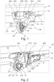
- Fig. 1 shows a front perspective view of a load introduction system 1 comprising an attachment unit 20 that includes two main pieces, i.e., a first attachment element 21 and a second attachment element 22, which are manufactured separately and subsequently assembled to each other.
- Fig. 1 shows the attachment unit 20 in the assembled state 50.
- the load introduction system 1 comprises an aerodynamic component 10 having a skin section 12 with an aerodynamic outer surface 14 and a protrusion 16 extending from the aerodynamic outer surface 14 of the skin section 12.
- the aerodynamic component 10 may have a box-like structure that is made of CFRP.
- the aerodynamic component 10 may be a multi-cell flap component that is manufactured as a CFRP single-piece structure.
- the protrusion 16 which extends from the outer surface 14 of the skin section 12 is formed by a plate-like structure, in particular a fin-like structure, that extends substantially perpendicular from the outer surface 14 of the skin section 12.
- the protrusion 16 may be a support structure to which the attachment unit 20 is fastened in order to transfer loads from the attachment unit 20 into the structure of the aerodynamic component 10 and vice versa.
- the attachment unit 20 may at least partially extend over the protrusion 16 of the aerodynamic component 10 as will be explained with reference Figs. 2 and 3 below.
- the attachment unit 20 is adapted to movably couple the aerodynamic component 10 to a base unit (not shown in Fig. 1 ).
- the attachment unit 20 comprises a first attachment element 21 and a second attachment element 22, wherein the first attachment element 21 has a mounting interface 21a that is configured to mount the first attachment element 21, and thus the attachment unit 20, to the skin section 12 and to the protrusion 16 of the aerodynamic component 10.
- the mounting interface 21a of the first attachment element 21 comprises at least one fastening element 15 which fastens the first attachment element 21 onto the outer surface 14 of the skin section 12 and at least one fastening element 17 which fastens the first attachment element 21 to the protrusion 16.
- the fastening elements may be screws, bolts, rivets, etc. However, other fastening mechanisms are possible.
- the mounting interface 21a of the first attachment element 21 may comprise a form-fit connection or a material connection in order to attach the first attachment element 21 to the outer surface 14 and/or to the protrusion 16.
- the attachment unit 20 further comprises a second attachment element 22, also having a mounting interface 22a that is configured to mount the second attachment element 22, and thus the attachment unit 20, to the skin section 12 and to the protrusion 16 of the aerodynamic component 10.
- the mounting interface 22a of the second attachment element 22 also comprises at least one fastening element (not shown) which fastens the second attachment element 22 onto the outer surface 14 of the skin section 12 and at least one fastening element (not shown) which fastens the second attachment element 22 to the protrusion 16.
- the fastening elements may be screws, bolts, rivets, etc. However, other fastening mechanisms are possible.
- the mounting interface 22a of the second attachment element 22 may comprise a form-fit connection or a material connection in order to attach the second attachment element 22 to the outer surface 14 and/or to the protrusion 16.
- first attachment element 21 has a contact surface 21b and the second attachment unit 22 also has a contact surface 22b.
- Both contact surfaces 21b, 22b are not visible in the Figures since the Figures show the assembled state 50 of the attachment unit 20 in which both surfaces are in contact with each other and overlap completely each other. The position where the contact surfaces 21b, 22b contact with each other is therefore indicated by a solid line that defines the boundary between the first attachment element 21 and the second attachment element 22.
- the first attachment element 21 has a first opening 21c and the second attachment element 22 also has a first opening 22c.
- the first opening 21c of the first attachment element 21 and the first opening 22c of the second attachment element 22 coaxially align with each other.
- the first opening 21c of the first attachment element 21 and the first opening 22c of the second attachment element 22 share a common central axis 23.
- the first openings 21c, 22c together form a lug for accommodating a bearing element 24 for receiving a coupling mechanism of the base unit.
- the first opening 21c of the first attachment element 21 and the first opening 22c of the second attachment element 22 cooperatively receive the coupling mechanism 31 (cf. Fig.
- first attachment element 21 directly contacts the second attachment element 22
- first openings 21c, 22c are directly arranged next to each other, i.e., with no axial distance between the opening 21c, 22c.
- first attachment element 21 is configured to provide a first load path from the first opening 21c of the first attachment element 21 to the mounting interface 21a of the first attachment element 21.
- second attachment element 22 is configured to provide a second load path from the first opening 22c of the second attachment element 22 to the mounting interface 22a of the second attachment element 22.
- the first attachment element 21 further comprises a second opening 21d and the second attachment element 22 further comprises a second opening 22d, wherein, in the assembled state 50 of the attachment unit 20, the second opening 21d of the first attachment element 21 and the second opening 22d of the second attachment element 22 are configured to cooperatively receive an actuation mechanism 32 (cf. Fig. 2 ).
- the second opening 21d of the first attachment element 21 is axially spaced apart from the second opening 22d of the second attachment element 22 and the actuation mechanism 32 (cf. Fig. 2 ) is partially arranged between the second opening 21d of the first attachment element 21 and the second opening 22d of the second attachment element 22.
- Two arms or flange elements 21e, 22e are provided in which the second openings 21d, 22d are located.
- the first attachment element 21 includes an arm or flange 21e into which the second opening 21d is integrated
- the second attachment element 22 includes an arm or flange 22e into which the second opening 22d is integrated.
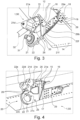
- Fig. 2 now shows a front perspective view of the load introduction system 1 of Fig. 1 , with an additional indication of the coupling mechanism 31 and the actuation mechanism 32. It is noted that only some parts of the coupling mechanism 31 and the actuation mechanism 32 are shown in Fig. 2 and that these mechanisms may comprise further parts not shown in the Figures.
- the coupling mechanism 31 is movably seated within the spherical bearing 24 which allows a certain degree of rotational movement of the coupling mechanism 31 inside the first openings 21c, 22c and around the central axis 23.
- the actuation mechanism 32 is movably seated within the second openings 21d, 22d, which allows a certain degree of rotational movement of the coupling mechanism 32 supported by second openings 21d, 22d (cf. also Fig. 1 ).
- Fig. 2 again shows the load introduction system 1 with the outer surface 14 of the skin section 12 of the aerodynamic component 10 and the protrusion 16 extending therefrom, as well as the attachment unit 20 that comprises the first attachment element 21 and the second attachment element 22, each of which is coupled via its respective mounting interfaces 21a, 22a to the skin section 12 and to the protrusion 16 (cf. also Fig. 1 ).
- fastening elements 26 are used to mount the first attachment element 21 to the second attachment element 22, such that in the assembled state 50 both attachment elements 21, 22 are pressed against each other at their respective contact surfaces.
- the fastening elements 26 may include bolts, screws, rivets, etc. that extend through the structure of the first and second attachment element 21, 22.
- Further fastening elements 17, for example in the form of bolts, screws, rivets, etc. fasten the first and second attachment element 21, 22 to the protrusion 16.
- connection element 29 is attached to the attachment unit 20, in particular, to both attachment elements 21, 22.
- the attachment unit 20 can be attached to the skin section 12 and to the protrusion 16 via the connection interfaces 21a, 22a, but also via the connection element 29 to a secondary connecting region 29a on the outer surface 14 of the skin section 12.
- the attachment unit 20 may be attached to the skin section 12 at two separate connecting regions on the outer surface 14, wherein these connecting regions are arranged at different sides of the protrusion 16.
- the connection element 29 may be fastened to the skin section 12 in the connecting region 29a using fastening elements like bolts, screws, rivets, etc.
- connection element 29 may additionally be fastened to another (second) protrusion 18 that, adjacent the connecting region 29a, extends from the outer surface 14 of the skin section 12.
- This connection to the second protrusion 18 may also include fastening elements like bolts, screws, rivets, etc.
- the connection element 29 may be attached to the first and second attachment element 21, 22 using fastening elements 29b, for example bolts, screws, rivets, etc.
- Fig. 3 shows a rear perspective view of the load introduction system 1 of Fig. 1 , with an additional indication of the coupling mechanism 31 which is movably supported with respect to the attachment unit 20 and with additional indication of the actuation mechanism 32 which is also movably supported in the second openings 21d, 22d as described above.
- the first and second attachment unit 21, 22 are shown as being assembled, fastened and pressed against each other using the fastening elements 26. It is recognizable that further fastening elements 15 are used to fasten the first attachment element 21, via the connection interface 21a, to the skin section 12 of the aerodynamic component 10.
- the fastening elements 17 which fasten the first attachment element 21 to the protrusion 16 are also shown.
- connection element 29 may be a separate component and may be attached to both attachment elements 21, 22 via fastening elements 29b, for example bolts, screws, rivets, etc.
- the first attachment element 21 may include a flange 21f to which the connection element 29 is attached.
- the second attachment element 22 may include a flange 22f to which the connection element 29 is also attached.
- the connection element 29 may include a bracket section having two arms between which the flanges 21f, 22f of the attachment elements 21, 22 are arranged when the first and second attachment element 21, 22 are fastened to the connection element 29.
- a second protrusion 18 extends from the outer surface 14 of the skin section 12.
- the connection element 29 may also be attached to the second protrusion 18 via fastening elements 19, for example via bolts, screws, rivets, etc.
- the connection element 29 may be attached to the skin section 12 at the connecting region 29a and, additionally, to the second protrusion 18.
- the second protrusion 18 may also comprise a plate-like, e.g., fin-like, structure similar to the first protrusion 16.
- Fig. 4 shows a front perspective view of the first and second attachment elements 21, 22 of Fig. 1 , illustrating the first openings 21c, 22c and the second openings 21d, 22d, all of which are integrated into the first and second attachment elements 21, 22.
- the second openings 21d, 22d are arranged within arms or flanges 21e, 22e of the respective attachment elements 21, 22.
- the fastening elements 26 used for mounting the first attachment element 21 to the second attachment element 22, the fastening elements 15 for fastening the first and second attachment elements 21, 22 to the skin section 12, as well as the fastening elements 17 for fastening the first and second attachment elements 21, 22 to the protrusion 16 are shown.
- the connection element 29 couples the attachment elements 21, 22 to a further connecting region on the skin section 12.
- first openings 21c, 22c are coaxially aligned with each other.
- the first openings 21c, 22c are thus defined by a hole or bore that extends through the first and second attachment element 21, 22. Since the attachment elements 21, 22 directly contact each other via their contact surfaces, there is no axial distance between the two first openings 21c, 22c. Both first openings 21c, 22c rather form a single continuous hole or bore through the attachment unit 20.
- Fig. 5 shows a rear perspective view of the first and second attachment elements 21, 22 of Fig. 1 , illustrating the first openings 21c, 22c and one second opening 21d.
- the second opening 21d is arranged within flange 21e of the first attachment element 21.
- the fastening elements 26 used for mounting the first attachment element 21 to the second attachment element 22, the fastening elements 15 for fastening the first and second attachment elements 21, 22 to the skin section 12, as well as the fastening elements 17 for fastening the first and second attachment elements 21, 22 to the protrusion 16 are shown.
- the connection element 29 couples the attachment elements 21, 22 to a further connecting region on the skin section 12.
- the connection element 29 couples the attachment elements 21, 22 to the second protrusion 18 via the fastening elements 19.
- the second protrusion 18 may be tilted relative to the first protrusion 16.
- first openings 21c, 22c are coaxially aligned with each other.
- the first openings 21c, 22c are thus defined by a hole or bore that extends through the first and second attachment element 21, 22 along the central axis 23. Since the attachment elements 21, 22 directly contact each other via their contact surfaces 21b, 22b, there is no axial distance between the two first openings 21c, 22c. Both first openings 21c, 22c rather form a single continuous hole or bore through the attachment unit 20.
- Fig. 6 shows an aircraft 100 comprising the load introduction system 1 of Fig. 1 .
- the aerodynamic component 10 is a flap structure 102 which is movably coupled to a wing structure 101 by the attachment unit 20.
- the base component 30 is formed by the wing structure 101 to which the flap structure 102 is fastened via the attachment unit 20 and the coupling mechanism 31 (cf. also Fig. 2 ).
- Fig. 7 shows a method for manufacturing a load introduction system, for example the load introduction system 1 of Fig. 1 above.
- a step S1 of the method an aerodynamic component 10 having a skin section 12 with an aerodynamic outer surface 14 and a protrusion 16 extending from the aerodynamic outer surface 14 of the skin section 12 is provided.
- a base unit 30 having a coupling mechanism 31 is provided in a step S2.
- a first attachment element 21 having a mounting interface 21a, a contact surface 21b and a first opening 21c is provided.
- a second attachment element 21 having a mounting interface 22a, a contact surface 22b and a first opening 22c is provided.
- a step S5 the first attachment element 21 and the second attachment element 22 are assembled such that the contact surface 21b of the first attachment element 21 and the contact surface 22b of the second attachment element 22 are in contact with each other and such that the first opening 21c of the first attachment element 21 and the first opening 22c of the second attachment element 22 coaxially align with each other.
- the first attachment element 21 is mounted to the aerodynamic component 10 via the mounting interface 21a of the first attachment element 21.
- the second attachment element 22 is mounted to the aerodynamic component 10 via the mounting interface 22a of the second attachment element 22.
- the coupling mechanism 31 of the base unit 30 is received both in the first opening 21c of the first attachment element 21 and in the first opening 22c of the second attachment element 22, thereby movably coupling the aerodynamic component 10 to the base unit 30.
Landscapes
- Engineering & Computer Science (AREA)
- Aviation & Aerospace Engineering (AREA)
- Mechanical Engineering (AREA)
- Connection Of Plates (AREA)
Abstract
Description
- The invention relates to improved attachment and load transmission concepts for aerodynamic structures. In particular, the invention relates to a load introduction system and a method for manufacturing a load introduction system.
- The transmission of loads among components of aerodynamic systems is an important aspect that has to be considered during the design process of such systems. For example, strength requirements, low manufacturing/assembly costs in combination with a reliable and stable manufacturing/assembly process are important aspects that have to be dealt with during the design process. When designing the corresponding components, load paths through these components can be analyzed and optimized so as to avoid load peaks in certain regions within the component structure. Such load peaks often occur at fastening elements like bolts which couple the components to each other. In particular, high tension forces may occur inside the bolts when coupling the components to each other.
-
EP 3 575 206 A1 describes a system for driving a flap arrangement between a retracted position and an extended position, a wing having such a system as well as an aircraft. -
EP 2 578 489 A2 - It may be seen as an object of the invention to improve the load transmission within an attachment unit for aerodynamic structures.
- A system and a method according to the features of the independent claims are provided. Further embodiments of the invention are evident from the dependent claims and from the following description.
- According to an aspect of the invention, a load introduction system is provided. The load introduction system comprises an aerodynamic component having a skin section with an aerodynamic outer surface and a protrusion extending from the aerodynamic outer surface of the skin section. The load introduction system further comprises an attachment unit for movably coupling the aerodynamic component to a base unit. The attachment unit comprises a first attachment element and a second attachment element, each of the first attachment element and the second attachment element having a mounting interface that is configured to mount the attachment unit to the skin section and to the protrusion of the aerodynamic component. Furthermore, each of the first attachment element and second attachment element has a contact surface, wherein the contact surface of the first attachment element and the contact surface of the second attachment element are in contact with each other, e.g., are pressed against each other, in an assembled state of the attachment unit. Each of the first attachment element and the second attachment element has a first opening for receiving a coupling mechanism of the base unit. In the assembled state of the attachment unit, the first opening of the first attachment element and the first opening of the second attachment element coaxially align with each other, such that the first opening of the first attachment element and the first opening of the second attachment element cooperatively receive the coupling mechanism of the base unit.
- The inventive load introduction system provides an attachment of the aerodynamic component to the base system while providing two independent load paths through the attachment. In particular, a doubling of a load path that extends through the attachment unit is achieved, thereby improving the redundancy of a load transmission between the aerodynamic component and the base system. For the inventive concept, a first load path between the aerodynamic component and the base system will extend through the first attachment element, and a second load path between the aerodynamic component and the base system will extend through the second attachment element.
- In an example, both load paths are independent from each other and do not affect each other, such that the load transmission through the first attachment element and between the aerodynamic component and the base system will not influence the load transmission within the second attachment element.
- The inventive load introduction system may be part of an aircraft system. For example, the load introduction system is a mechanical device which is configured to mount aerodynamic components, in particular movables like flaps, slats, leading edge high lift devices, ailerons, spoilers, flaperons, vertical and horizontal stabilizers, elevators, rudders or doors to a corresponding base system.
- In the following, the load introduction system will be mainly described as being used for the attachment and load transmission of an aircraft flap to an aircraft wing. However, it should be understood that the load introduction system can also be used for other technical applications or for attaching any other of the above-mentioned exemplary aerodynamic components.
- The aerodynamic component may comprise an integrally manufactured single-piece structure. For example, the aerodynamic component may comprise or consist of a carbon fiber reinforced plastic (CFRP) material. In particular, if the aerodynamic component is a flap component, it may be designed to form a multi-cell flap design. As will be explained below, such a flap design for the aerodynamic component may additionally include one or more load introduction protrusions, for example fin-like protrusions, extending from the outer surface of the aerodynamic component. Such protrusions may also be made of CFRP material and/or may act as load introduction features on the aerodynamic component which at least partly receive the load transmission from the attachment unit.
- The attachment unit which, in the assembled state, comprises the first attachment element and the second attachment element being mounted to each other may be a bracket or bracket-like structure. In particular, the attachment unit may be mounted at one or more connecting regions onto the outer surface of the aerodynamic component.
- The first attachment element has its own mounting interface that mounts the first attachment element to the aerodynamic component, in particular to the skin section and to the protrusion of the aerodynamic component. The mounting interface may comprise additional fastening elements, like rivets, screws or bolts, to mount the first attachment element to the outer surface and protrusion of the aerodynamic component. Analogously, the second attachment element has its own mounting interface that mounts the second attachment element to the aerodynamic component, in particular to the skin section and to the protrusion of the aerodynamic component. The mounting interface may comprise additional fastening elements, like rivets, screws or bolts, to mount the second attachment element to the outer surface and protrusion of the aerodynamic component. It is possible, that the mounting interfaces of the first and second attachment element each comprise a form fit connection or a material bond, like a weld joint or adhesive joint etc., to couple the respective attachment element to the aerodynamic component.
- The first attachment element has a contact surface which may be present in the form of an entirely flat surface. Analogously, the second attachment element has a contact surface which may also be present in the form of an entirely flat surface. Both contact surfaces are in contact with each other, e.g., with their entire flat surfaces, when the attachment unit is in the assembled state. In particular, fastening elements can be used to fasten both attachment elements to each other, thereby pressing the respective contact surfaces against each other.
- The first and second attachment elements may be milled parts which are assembled to each other. For example, the attachment elements may be metal parts. However, it is possible that the attachment elements comprise or consist of other materials, like for instance fiber reinforced materials, etc.
- Both the first attachment element and the second attachment element have a first opening, herein also referred to as a lug, for receiving a coupling mechanism of the base unit. The first opening of the first attachment element may be a hole or bore that extends through the first attachment element. In an example, the first opening of the first attachment element may extend through the contact surface of the first attachment element. The first opening of the second attachment unit may, as well, be a hole or bore that extends through the second attachment element. In an example, the first opening of the second attachment unit may extend through the contact surface of the second attachment element.
- Both first openings coaxially align with each other in the assembled state of the attachment unit. In addition, both openings be arranged directly adjacent to each other in the assembled state, i.e., with no axial distance to each other. As the first openings may have the same size, in particular the same diameter, they appear as a single opening or lug for receiving the coupling mechanism of the base unit, although the respective openings extend within different elements, i.e., within the first attachment element and the second attachment element, respectively.
- A main load transmission through the first attachment element may occur within the structure of the first attachment element between the first opening and the mounting interface of the first attachment element. A main load transmission through the second attachment element may occur within the structure of the second attachment element between the first opening and the mounting interface of the second attachment element. The load transmissions may thus be transmitted via the mounting interfaces of the attachment elements and into the skin section and the protrusion since both attachment elements are mounted to the skin section and the protrusion via the respective mounting interfaces.
- According to an embodiment, the first attachment element and the second attachment element are separately manufactured parts which are mounted together in the assembled state.
- In particular, both attachment elements have no material connection or structural connection between each other that could transfer a load between the attachment elements. However, it is noted that both attachment elements may be fastened to each other via separate fastening elements that fix the attachment elements to each other, via which a minor load transfer between the attachment elements might occur. Nevertheless, both attachment elements may be designed such that the main load transmission between the respective first openings and the respective mounting interfaces extends solely through the material or structure of the attachment elements themselves. The inventive design of the attachment unit may provide that these main load transmissions do not influence each other or interfere with each other.
- According to an embodiment, the first attachment element is configured to provide a first load path from the first opening of the first attachment element to the mounting interface of the first attachment element, wherein the second attachment element is configured to provide a second load path from the first opening of the second attachment element to the mounting interface of the second attachment element, and wherein the first load path is independent from the second load path.
- The first and second load paths may correspond to the above-mentioned main load transmissions that extend only through the structure of the respective attachment elements. The term "independent" may in this case be understood in that the load transmissions along these load paths do not influence each other. That is, the main load transmission along the first load path through the structure of the first attachment element does not interfere with or affect the main load transmission along the second load path through the structure of the second attachment element, and vice versa.
- According to an embodiment, the first opening of the first attachment element and the first opening of the second attachment element together accommodate a bearing element for receiving the coupling mechanism of the base unit.
- The bearing element may be a spherical bearing that movably, e.g., rotatably, couples the coupling mechanism of the base unit to the attachment unit. The spherical bearing may be a separate element that is inserted into the first openings after the first and second attachment elements have been mounted and fixed to each other.
- According to an embodiment, the first attachment element is mounted to the second attachment element via at least one fastening element, in the assembled state of the attachment unit.
- For example, bolts, rivets, screws etc. can be used to mount or fix the first attachment element to the second attachment element. It is possible that the connection between the first attachment element and the second attachment element provided by the at least one fastening element is a releasable connection, and there might not be any material connection between the attachment elements.
- According to an embodiment, the first attachment element comprises a second opening and also the second attachment element comprises a second opening, wherein, in the assembled state of the attachment unit, the second opening of the first attachment element and the second opening of the second attachment element are configured to cooperatively receive an actuation mechanism of the base unit.
- That is, the attachment unit may be coupled to the base system via two different devices, e.g., linkages. In particular, the attachment unit is coupled to the base unit via the coupling mechanism that is received by the first openings, e.g., within the spherical bearing, and additionally via the actuation mechanism that is received by the second openings. The second openings may define holes or bores extending through respective portions or flanges of the first and second attachment element. As will be described in more detail below, an additional connector may be provided that includes both second openings such that the second openings are integrated into one single structural element that is mounted to the first and second attachment element in the assembled state.
- According to an embodiment, the second opening of the first attachment element is axially spaced apart from the second opening of the second attachment element, and the actuation mechanism of the base unit is at least partially arranged between the second opening of the first attachment element and the second opening of the second attachment element.
- For example, the second openings may provide a hinge element for rotatably coupling the attachment unit to the actuation mechanism. In the assembled state, the first and second attachment element may together provide a fork-like structure having arms or flanges defined by the attachment elements. For example, the first attachment element may comprise an arm or flange extending from a main body of the first attachment element and second attachment element may also comprise an arm or flange extending from a main body of the second attachment element. Each arm or flange includes one of the second openings in which the actuation mechanism can be rotatably coupled.
- According to an embodiment, the attachment unit comprises a connector that is mounted to both the first attachment element and the second attachment element, wherein the connector comprises two openings being configured to cooperatively receive an actuation mechanism of the base unit.
- In contrast, to the above-mentioned embodiment where each of the attachment elements comprises one of the second openings, it is thus also possible to integrate the second openings in one single-piece connector which itself is attached to both attachment elements. In this case, the connector defines the fork-like structure instead of the two assembled attachment elements as described above.
- According to an embodiment, the mounting interface of the first attachment element comprises at least one fastening element which fastens the first attachment element onto the outer surface of the skin section and further comprises at least one fastening element which fastens the first attachment element to the protrusion. Additionally or alternatively, the mounting interface of the second attachment element comprises at least one fastening element which fastens the second attachment element onto the outer surface of the skin section and further comprises at least one fastening element which fastens the second attachment element to the protrusion.
- The at least one fastening element for each fastening can comprise multiple fastening elements. Such fastening elements may include rivets, bolts, screws, pins and/or combinations thereof. It is possible that form-fit connections or material bonds can also be applied for mounting the respective attachment element to the skin section and/or to the protrusion.
- According to an embodiment, the protrusion on the outer surface of the skin section is formed by a plate-like structure that extends substantially perpendicular or exactly perpendicular from the outer surface of the skin section.
- The protrusion may be a fin that protrudes from the outer surface. The fin may be part of a support structure that is covered by the skin section such that only the fin of the support structure extends through the skin section and away from the outer surface of the skin section. The fin may be fixedly arranged with respect to the skin section or may be integrally formed with the skin section. As explained above, the aerodynamic component may be a flap component, e.g., a trailing edge flap, for an aircraft wing. In this case, the fin may be oriented in a transverse direction relative to the flight direction of the aircraft. Such an orientation of the fin will be shown in the Figures described below. However, the fin can also be oriented in flight direction, i.e., parallel to the flight direction, of the aircraft. The expression "substantially perpendicular" in the present context takes into account manufacturing tolerances due to the specifically applied manufacturing technique for providing the plate-like structure at the outer surface of the skin section. Small deviations from an exactly perpendicular orientation due to the applied tools are within the scope of said expression.
- The plate-like structure itself may comprise the same material as the skin section, for example a fiber reinforced material like CFRP. A metal or metal alloy can also be used. However, different materials can be used for the plate-like structure and the skin section.
- According to an embodiment, the attachment unit at least partially extends over the protrusion of the aerodynamic component.
- In other words, the attachment unit, when being mounted to the aerodynamic component, at least partially bridges the protrusion.
- According to an embodiment, the extension of the protrusion from the aerodynamic outer surface of the skin section divides a space adjacent the skin section into a front space and a rear space, wherein the attachment unit extends over, e.g., bridges, the protrusion of the aerodynamic component such that the attachment unit is partially arranged in the front space relative to the protrusion and such that the attachment unit is partially arranged in the rear space relative to the protrusion.
- In this case, the attachment unit which includes the first and second attachment elements extends and thus bridges over the protrusion from the front space to the rear space, with respect to the protrusion. The contact surfaces of the first and second attachment elements thus also extend over the protrusion. A mounting of the attachment unit to the aerodynamic component may be present in the front space, e.g., via the mounting interfaces described above, but additionally may be present in the rear space via an additional interface.
- According to an embodiment, the base component is a wing structure, and the aerodynamic component is a flap structure which is movably coupled to the wing structure by the attachment unit.
- The wing structure may be part of an aircraft wing and the flap structure may be part of a trailing edge flap system of the aircraft wing.
- According to an aspect, an aircraft comprising a load introduction system as described herein is provided.
- According to another aspect, a method for manufacturing a load introduction system is provided. A step of the method comprises providing an aerodynamic component having a skin section with an aerodynamic outer surface and a protrusion extending from the aerodynamic outer surface of the skin section. In another step, the method comprises providing a base unit having a coupling mechanism. Another step comprises manufacturing a first attachment element having a mounting interface, a contact surface and a first opening. Another step comprises manufacturing a second attachment element having a mounting interface, a contact surface and a first opening. Another step comprises assembling the first attachment element and the second attachment element such that the contact surface of the first attachment element and the contact surface of the second attachment element are in contact with each other and such that the first opening of the first attachment element and the first opening of the second attachment element coaxially align with each other. Another step comprises mounting the first attachment element to the aerodynamic component via the mounting interface of the first attachment element. Another step comprises mounting the second attachment element to the aerodynamic component via the mounting interface of the second attachment element. Another step comprises receiving the coupling mechanism of the base unit both in the first opening of the first attachment element and in the first opening of the second attachment element, thereby movably coupling the aerodynamic component to the base unit. These method steps may be performed in the indicated order.
- According to an embodiment, manufacturing the first attachment element and manufacturing the second attachment element comprises milling the first attachment element and milling the second attachment element as separate parts, before assembling the first attachment element and the second attachment element.
- The present invention will hereinafter be described in conjunction with the following drawing figures, wherein like numerals denote like elements, and wherein:
- Fig. 1
- shows a front perspective view of a load introduction system including an attachment unit which is divided into a first and a second attachment element.
- Fig. 2
- shows a front perspective view of the load introduction system of
Fig. 1 , with an additional indication of a coupling mechanism and an actuation mechanism. - Fig. 3
- shows a rear perspective view of the load introduction system of
Fig. 1 , with an additional indication of a coupling mechanism and an actuation mechanism. - Fig. 4
- shows a front perspective view of the first and second attachment elements of
Fig. 1 , illustrating openings integrated into the first and second attachment elements. - Fig. 5
- shows a rear perspective view of the first and second attachment elements of
Fig. 1 , illustrating openings integrated into the first and second attachment elements. - Fig. 6
- shows an aircraft comprising the load introduction system of
Fig. 1 . - Fig. 7
- shows a method for manufacturing a load introduction system.
- The representations and illustrations in the drawings are schematic and not to scale. A better understanding of the method and system described above may be obtained through a review of the illustrations accompanying this application together with a review of the detailed description that follows.
-
Fig. 1 shows a front perspective view of a load introduction system 1 comprising anattachment unit 20 that includes two main pieces, i.e., afirst attachment element 21 and asecond attachment element 22, which are manufactured separately and subsequently assembled to each other.Fig. 1 shows theattachment unit 20 in the assembled state 50. The load introduction system 1 comprises anaerodynamic component 10 having askin section 12 with an aerodynamicouter surface 14 and aprotrusion 16 extending from the aerodynamicouter surface 14 of theskin section 12. Theaerodynamic component 10 may have a box-like structure that is made of CFRP. For example, theaerodynamic component 10 may be a multi-cell flap component that is manufactured as a CFRP single-piece structure. - The
protrusion 16 which extends from theouter surface 14 of theskin section 12 is formed by a plate-like structure, in particular a fin-like structure, that extends substantially perpendicular from theouter surface 14 of theskin section 12. Theprotrusion 16 may be a support structure to which theattachment unit 20 is fastened in order to transfer loads from theattachment unit 20 into the structure of theaerodynamic component 10 and vice versa. Theattachment unit 20 may at least partially extend over theprotrusion 16 of theaerodynamic component 10 as will be explained with referenceFigs. 2 and3 below. - The
attachment unit 20 is adapted to movably couple theaerodynamic component 10 to a base unit (not shown inFig. 1 ). As indicated above, theattachment unit 20 comprises afirst attachment element 21 and asecond attachment element 22, wherein thefirst attachment element 21 has a mountinginterface 21a that is configured to mount thefirst attachment element 21, and thus theattachment unit 20, to theskin section 12 and to theprotrusion 16 of theaerodynamic component 10. As can be seen inFig. 3 , the mountinginterface 21a of thefirst attachment element 21 comprises at least onefastening element 15 which fastens thefirst attachment element 21 onto theouter surface 14 of theskin section 12 and at least onefastening element 17 which fastens thefirst attachment element 21 to theprotrusion 16. The fastening elements may be screws, bolts, rivets, etc. However, other fastening mechanisms are possible. For example, the mountinginterface 21a of thefirst attachment element 21 may comprise a form-fit connection or a material connection in order to attach thefirst attachment element 21 to theouter surface 14 and/or to theprotrusion 16. - The
attachment unit 20 further comprises asecond attachment element 22, also having a mountinginterface 22a that is configured to mount thesecond attachment element 22, and thus theattachment unit 20, to theskin section 12 and to theprotrusion 16 of theaerodynamic component 10. As for the mountinginterface 21a of the first attachment element, the mountinginterface 22a of thesecond attachment element 22 also comprises at least one fastening element (not shown) which fastens thesecond attachment element 22 onto theouter surface 14 of theskin section 12 and at least one fastening element (not shown) which fastens thesecond attachment element 22 to theprotrusion 16. The fastening elements may be screws, bolts, rivets, etc. However, other fastening mechanisms are possible. For example, the mountinginterface 22a of thesecond attachment element 22 may comprise a form-fit connection or a material connection in order to attach thesecond attachment element 22 to theouter surface 14 and/or to theprotrusion 16. - Furthermore, the
first attachment element 21 has acontact surface 21b and thesecond attachment unit 22 also has acontact surface 22b. Both contact surfaces 21b, 22b are not visible in the Figures since the Figures show the assembled state 50 of theattachment unit 20 in which both surfaces are in contact with each other and overlap completely each other. The position where the contact surfaces 21b, 22b contact with each other is therefore indicated by a solid line that defines the boundary between thefirst attachment element 21 and thesecond attachment element 22. - The
first attachment element 21 has afirst opening 21c and thesecond attachment element 22 also has afirst opening 22c. In the assembled state 50 of theattachment unit 20, thefirst opening 21c of thefirst attachment element 21 and thefirst opening 22c of thesecond attachment element 22 coaxially align with each other. Thus, thefirst opening 21c of thefirst attachment element 21 and thefirst opening 22c of thesecond attachment element 22 share a commoncentral axis 23. Thefirst openings bearing element 24 for receiving a coupling mechanism of the base unit. In particular, thefirst opening 21c of thefirst attachment element 21 and thefirst opening 22c of thesecond attachment element 22 cooperatively receive the coupling mechanism 31 (cf.Fig. 2 ) via thebearing element 24 which is arranged in thefirst openings first attachment element 21 directly contacts thesecond attachment element 22, thefirst openings opening - It is noted that the
first attachment element 21 is configured to provide a first load path from thefirst opening 21c of thefirst attachment element 21 to the mountinginterface 21a of thefirst attachment element 21. Analogously, thesecond attachment element 22 is configured to provide a second load path from thefirst opening 22c of thesecond attachment element 22 to the mountinginterface 22a of thesecond attachment element 22. This design in which theattachment elements first attachment element 21 is independent from the second load path through thesecond attachment element 22. A redundant load path design can thus be provided by theattachment unit 20 in the assembled state 50. - The
first attachment element 21 further comprises asecond opening 21d and thesecond attachment element 22 further comprises asecond opening 22d, wherein, in the assembled state 50 of theattachment unit 20, thesecond opening 21d of thefirst attachment element 21 and thesecond opening 22d of thesecond attachment element 22 are configured to cooperatively receive an actuation mechanism 32 (cf.Fig. 2 ). Thesecond opening 21d of thefirst attachment element 21 is axially spaced apart from thesecond opening 22d of thesecond attachment element 22 and
the actuation mechanism 32 (cf.Fig. 2 ) is partially arranged between thesecond opening 21d of thefirst attachment element 21 and thesecond opening 22d of thesecond attachment element 22. Two arms orflange elements second openings first attachment element 21 includes an arm orflange 21e into which thesecond opening 21d is integrated, and thesecond attachment element 22 includes an arm orflange 22e into which thesecond opening 22d is integrated. -
Fig. 2 now shows a front perspective view of the load introduction system 1 ofFig. 1 , with an additional indication of thecoupling mechanism 31 and theactuation mechanism 32. It is noted that only some parts of thecoupling mechanism 31 and theactuation mechanism 32 are shown inFig. 2 and that these mechanisms may comprise further parts not shown in the Figures. Thecoupling mechanism 31 is movably seated within thespherical bearing 24 which allows a certain degree of rotational movement of thecoupling mechanism 31 inside thefirst openings central axis 23. Theactuation mechanism 32 is movably seated within thesecond openings coupling mechanism 32 supported bysecond openings Fig. 1 ). -
Fig. 2 again shows the load introduction system 1 with theouter surface 14 of theskin section 12 of theaerodynamic component 10 and theprotrusion 16 extending therefrom, as well as theattachment unit 20 that comprises thefirst attachment element 21 and thesecond attachment element 22, each of which is coupled via itsrespective mounting interfaces skin section 12 and to the protrusion 16 (cf. alsoFig. 1 ). - As shown in
Fig. 2 ,fastening elements 26 are used to mount thefirst attachment element 21 to thesecond attachment element 22, such that in the assembled state 50 bothattachment elements fastening elements 26 may include bolts, screws, rivets, etc. that extend through the structure of the first andsecond attachment element Further fastening elements 17, for example in the form of bolts, screws, rivets, etc. fasten the first andsecond attachment element protrusion 16. - In
Fig. 2 , it is also recognizable that theattachment unit 20 extends over theprotrusion 16. In particular, aconnection element 29 is attached to theattachment unit 20, in particular, to bothattachment elements attachment unit 20 can be attached to theskin section 12 and to theprotrusion 16 via theconnection interfaces connection element 29 to a secondary connectingregion 29a on theouter surface 14 of theskin section 12. In other words, theattachment unit 20 may be attached to theskin section 12 at two separate connecting regions on theouter surface 14, wherein these connecting regions are arranged at different sides of theprotrusion 16. Theconnection element 29 may be fastened to theskin section 12 in the connectingregion 29a using fastening elements like bolts, screws, rivets, etc. Theconnection element 29 may additionally be fastened to another (second)protrusion 18 that, adjacent the connectingregion 29a, extends from theouter surface 14 of theskin section 12. This connection to thesecond protrusion 18 may also include fastening elements like bolts, screws, rivets, etc. Theconnection element 29 may be attached to the first andsecond attachment element fastening elements 29b, for example bolts, screws, rivets, etc. -
Fig. 3 shows a rear perspective view of the load introduction system 1 ofFig. 1 , with an additional indication of thecoupling mechanism 31 which is movably supported with respect to theattachment unit 20 and with additional indication of theactuation mechanism 32 which is also movably supported in thesecond openings second attachment unit fastening elements 26. It is recognizable thatfurther fastening elements 15 are used to fasten thefirst attachment element 21, via theconnection interface 21a, to theskin section 12 of theaerodynamic component 10. Thefastening elements 17 which fasten thefirst attachment element 21 to theprotrusion 16 are also shown. - As can be recognized in
Fig. 3 , theattachment unit 20 and thus thefirst attachment element 21 and thesecond attachment element 22 extend over theprotrusion 16 such that theattachment unit 20 is also attached via theconnection element 29
to theskin section 12 in the connectingregion 29a. Theconnection element 29 may be a separate component and may be attached to bothattachment elements fastening elements 29b, for example bolts, screws, rivets, etc. In particular, thefirst attachment element 21 may include aflange 21f to which theconnection element 29 is attached. Accordingly, thesecond attachment element 22 may include aflange 22f to which theconnection element 29 is also attached. Theconnection element 29 may include a bracket section having two arms between which theflanges attachment elements second attachment element connection element 29. - As can be seen in
Fig. 3 , asecond protrusion 18 extends from theouter surface 14 of theskin section 12. Theconnection element 29 may also be attached to thesecond protrusion 18 viafastening elements 19, for example via bolts, screws, rivets, etc. Thus, theconnection element 29 may be attached to theskin section 12 at the connectingregion 29a and, additionally, to thesecond protrusion 18. It is noted that thesecond protrusion 18 may also comprise a plate-like, e.g., fin-like, structure similar to thefirst protrusion 16. -
Fig. 4 shows a front perspective view of the first andsecond attachment elements Fig. 1 , illustrating thefirst openings second openings second attachment elements second openings flanges respective attachment elements fastening elements 26 used for mounting thefirst attachment element 21 to thesecond attachment element 22, thefastening elements 15 for fastening the first andsecond attachment elements skin section 12, as well as thefastening elements 17 for fastening the first andsecond attachment elements protrusion 16 are shown. As described above, theconnection element 29 couples theattachment elements skin section 12. - From
Fig. 4 , it is apparent that thefirst openings first openings second attachment element attachment elements first openings first openings attachment unit 20. -
Fig. 5 shows a rear perspective view of the first andsecond attachment elements Fig. 1 , illustrating thefirst openings second opening 21d. As can be clearly seen in this Figure, thesecond opening 21d is arranged withinflange 21e of thefirst attachment element 21. Again, thefastening elements 26 used for mounting thefirst attachment element 21 to thesecond attachment element 22, thefastening elements 15 for fastening the first andsecond attachment elements skin section 12, as well as thefastening elements 17 for fastening the first andsecond attachment elements protrusion 16 are shown. As described above, theconnection element 29 couples theattachment elements skin section 12. In particular, theconnection element 29 couples theattachment elements second protrusion 18 via thefastening elements 19. Thesecond protrusion 18 may be tilted relative to thefirst protrusion 16. - From
Fig. 5 , it is apparent that thefirst openings first openings second attachment element central axis 23. Since theattachment elements contact surfaces first openings first openings attachment unit 20. -
Fig. 6 shows anaircraft 100 comprising the load introduction system 1 ofFig. 1 . Theaerodynamic component 10 is a flap structure 102 which is movably coupled to a wing structure 101 by theattachment unit 20. In other words, the base component 30 is formed by the wing structure 101 to which the flap structure 102 is fastened via theattachment unit 20 and the coupling mechanism 31 (cf. alsoFig. 2 ). -
Fig. 7 shows a method for manufacturing a load introduction system, for example the load introduction system 1 ofFig. 1 above. In a step S1 of the method, anaerodynamic component 10 having askin section 12 with an aerodynamicouter surface 14 and aprotrusion 16 extending from the aerodynamicouter surface 14 of theskin section 12 is provided. In a step S2, a base unit 30 having acoupling mechanism 31 is provided. In a step S3, afirst attachment element 21 having a mountinginterface 21a, acontact surface 21b and afirst opening 21c is provided. In a step S4, asecond attachment element 21 having a mountinginterface 22a, acontact surface 22b and afirst opening 22c is provided. In a step S5, thefirst attachment element 21 and thesecond attachment element 22 are assembled such that thecontact surface 21b of thefirst attachment element 21 and thecontact surface 22b of thesecond attachment element 22 are in contact with each other and such that thefirst opening 21c of thefirst attachment element 21 and thefirst opening 22c of thesecond attachment element 22 coaxially align with each other. In a step S6, thefirst attachment element 21 is mounted to theaerodynamic component 10 via the mountinginterface 21a of thefirst attachment element 21. In a step S7, thesecond attachment element 22 is mounted to theaerodynamic component 10 via the mountinginterface 22a of thesecond attachment element 22. In a step S8, thecoupling mechanism 31 of the base unit 30 is received both in thefirst opening 21c of thefirst attachment element 21 and in thefirst opening 22c of thesecond attachment element 22, thereby movably coupling theaerodynamic component 10 to the base unit 30.
Claims (15)
- A load introduction system (1), comprising:an aerodynamic component (10) having a skin section (12) with an aerodynamic outer surface (14) and a protrusion (16) extending from the aerodynamic outer surface (14) of the skin section (12);an attachment unit (20) for movably coupling the aerodynamic component (10) to a base unit (30);wherein the attachment unit (20) comprises a first attachment element (21) and a second attachment element (22), each of the first attachment element (21) and the second attachment element (22) having a mounting interface (21a, 22a) that is configured to mount the attachment unit (20) to the skin section (12) and to the protrusion (16) of the aerodynamic component (10);wherein each of the first attachment element (21) and second attachment element (22) has a contact surface (21b, 22b);wherein the contact surface (21b) of the first attachment element (21) and the contact surface (22b) of the second attachment element (22) are in contact with each other in an assembled state (50) of the attachment unit (20);wherein each of the first attachment element (21) and the second attachment element (22) has a first opening (21c, 22c) for receiving a coupling mechanism (31) of the base unit (30);wherein, in the assembled state (50) of the attachment unit (20), the first opening (21c) of the first attachment element (21) and the first opening (22c) of the second attachment element (22) coaxially align with each other, such that the first opening (21c) of the first attachment element (21) and the first opening (22c) of the second attachment element (22) cooperatively receive the coupling mechanism (31) of the base unit (30).
- The load introduction system (1) of claim 1,
wherein the first attachment element (21) and the second attachment (22) element are separately manufactured parts which are mounted together in the assembled state (50). - The load introduction system (1) according to any one of the preceding claims,wherein the first attachment element (21) is configured to provide a first load path from the first opening (21c) of the first attachment element (21) to the mounting interface (21a) of the first attachment element (21);wherein the second attachment element (22) is configured to provide a second load path from the first opening (22c) of the second attachment element (22) to the mounting interface (22a) of the second attachment element (22);wherein the first load path is independent from the second load path.
- The load introduction system (1) according to any one of the preceding claims,
wherein the first opening (21c) of the first attachment element (21) and the first opening (22c) of the second attachment element (22) together accommodate a bearing element (24) for receiving the coupling mechanism (31) of the base unit (30). - The load introduction system (1) according to any one of the preceding claims,
wherein, in the assembled state (50) of the attachment unit (20), the first attachment element (21) is mounted to the second attachment element (22) via at least one fastening element (26). - The load introduction system (1) according to any one of the preceding claims,wherein the first attachment element (21) comprises a second opening (21d);wherein the second attachment element (22) comprises a second opening (22d);wherein, in the assembled state (50) of the attachment unit (20), the second opening (21d) of the first attachment element (21) and the second opening (22d) of the second attachment element (22) are configured to cooperatively receive an actuation mechanism (32) of the base unit (30).
- The load introduction system (1) according to claim 6,wherein the second opening (21d) of the first attachment element (21) is axially spaced apart from the second opening (22d) of the second attachment element (22); andwherein the actuation mechanism (32) of the base unit (30) is at least partially arranged between the second opening (21d) of the first attachment element (21) and the second opening (22d) of the second attachment element (22).
- The load introduction system (1) according to any one of claims 1 to 5,
wherein the attachment unit (20) comprises a connector that is mounted to both the first attachment element (21) and the second attachment element (22), wherein the connector comprises two openings (21d, 22d) being configured to cooperatively receive an actuation mechanism (32) of the base unit (30). - The load introduction system (1) according to any one of the preceding claims,
wherein the mounting interface (21a) of the first attachment element (21) comprises at least one fastening element (15) which fastens the first attachment element (21) onto the outer surface (14) of the skin section (12) and at least one fastening element (17) which fastens the first attachment element (21) to the protrusion (16); and/or
wherein the mounting interface (22a) of the second attachment element (22) comprises at least one fastening element which fastens the second attachment element (22) onto the outer surface (14) of the skin section (12) and at least one fastening element which fastens the second attachment element (22) to the protrusion (16). - The load introduction system (1) according to any one of the preceding claims,
wherein the protrusion (16) on the outer surface (14) of the skin section (12) is formed by a plate-like structure that extends substantially perpendicular from the outer surface (14) of the skin section (12). - The load introduction system (1) according to any one of the preceding claims,
wherein the attachment unit (20) at least partially extends over the protrusion (16) of the aerodynamic component (10). - The load introduction system (1) according to any one of the preceding claims,wherein the extension of the protrusion (16) from the aerodynamic outer surface (14) of the skin section (12) divides a space adjacent the skin section into a front space and a rear space;wherein the attachment unit (20) extends over the protrusion (16) of the aerodynamic component (10) such that the attachment unit (20) is partially arranged in the front space relative to the protrusion (16) and such that the attachment unit (20) is partially arranged in the rear space relative to the protrusion (16).
- The load introduction system (1) according to any one of the preceding claims,wherein the base component (30) is a wing structure (101); andwherein the aerodynamic component (10) is a flap structure (102) which is movably coupled to the wing structure (101) by the attachment unit (20).
- An aircraft (100) comprising a load introduction system (1) according to any one of the preceding claims.
- A method for manufacturing a load introduction system (1), comprising:providing an aerodynamic component (10) having a skin section (12) with an aerodynamic outer surface (14) and a protrusion (16) extending from the aerodynamic outer surface (14) of the skin section (12, S1);providing a base unit (30) having a coupling mechanism (31, S2);manufacturing a first attachment element (21) having a mounting interface (21a), a contact surface (21b) and a first opening (21c, S3);manufacturing a second attachment element (21) having a mounting interface (22a), a contact surface (22b) and a first opening (22c, S4);assembling the first attachment element (21) and the second attachment element (22) such that the contact surface (21b) of the first attachment element (21) and the contact surface (22b) of the second attachment element (22) are in contact with each other and such that the first opening (21c) of the first attachment element (21) and the first opening (22c) of the second attachment element (22) coaxially align with each other (S5);mounting the first attachment element (21) to the aerodynamic component (10) via the mounting interface (21a) of the first attachment element (21, S6);mounting the second attachment element (22) to the aerodynamic component (10) via the mounting interface (22a) of the second attachment element (22, S7);receiving the coupling mechanism (31) of the base unit (30) both in the first opening (21c) of the first attachment element (21) and in the first opening (22c) of the second attachment element (22), thereby movably coupling the aerodynamic component (10) to the base unit (30, S8).
Priority Applications (3)
| Application Number | Priority Date | Filing Date | Title |
|---|---|---|---|
| EP22213593.1A EP4385887B1 (en) | 2022-12-14 | 2022-12-14 | Load introduction system and method for manufacturing a load introduction system |
| CN202311687755.9A CN118182817A (en) | 2022-12-14 | 2023-12-11 | Load introduction system and method for manufacturing a load introduction system |
| US18/537,072 US12377957B2 (en) | 2022-12-14 | 2023-12-12 | Load introduction system and method for manufacturing a load introduction system |
Applications Claiming Priority (1)
| Application Number | Priority Date | Filing Date | Title |
|---|---|---|---|
| EP22213593.1A EP4385887B1 (en) | 2022-12-14 | 2022-12-14 | Load introduction system and method for manufacturing a load introduction system |
Publications (2)
| Publication Number | Publication Date |
|---|---|
| EP4385887A1 true EP4385887A1 (en) | 2024-06-19 |
| EP4385887B1 EP4385887B1 (en) | 2026-02-18 |
Family
ID=84535968
Family Applications (1)
| Application Number | Title | Priority Date | Filing Date |
|---|---|---|---|
| EP22213593.1A Active EP4385887B1 (en) | 2022-12-14 | 2022-12-14 | Load introduction system and method for manufacturing a load introduction system |
Country Status (3)
| Country | Link |
|---|---|
| US (1) | US12377957B2 (en) |
| EP (1) | EP4385887B1 (en) |
| CN (1) | CN118182817A (en) |
Families Citing this family (1)
| Publication number | Priority date | Publication date | Assignee | Title |
|---|---|---|---|---|
| EP4282751B1 (en) * | 2022-05-24 | 2025-08-27 | Airbus Operations GmbH | Load introduction system and a method for manufacturing a load introduction system |
Citations (6)
| Publication number | Priority date | Publication date | Assignee | Title |
|---|---|---|---|---|
| EP2578489A2 (en) | 2011-10-07 | 2013-04-10 | Airbus Operations Limited | Flap support |
| US20150329197A1 (en) * | 2014-05-13 | 2015-11-19 | Airbus Operations Gmbh | Flow Body With A Load Introduction Element Integrated Therein, Method For Manufacturing A Flow Body, And Aircraft With Such A Flow Body |
| EP3323712A1 (en) * | 2016-11-21 | 2018-05-23 | The Boeing Company | Aircraft flap hinge |
| EP3575206A1 (en) | 2018-06-01 | 2019-12-04 | Airbus Operations GmbH | System for driving a flap arrangement between a retracted position and an extended position |
| US20220185449A1 (en) * | 2020-12-02 | 2022-06-16 | The Boeing Company | Apparatus, system and method for supporting a wing flap of an aircraft |
| EP4059835A1 (en) * | 2021-03-16 | 2022-09-21 | The Boeing Company | Three piece failsafe clevis |
Family Cites Families (1)
| Publication number | Priority date | Publication date | Assignee | Title |
|---|---|---|---|---|
| GB2624887A (en) * | 2022-11-29 | 2024-06-05 | Airbus Operations Ltd | Aircraft wing assembly |
-
2022
- 2022-12-14 EP EP22213593.1A patent/EP4385887B1/en active Active
-
2023
- 2023-12-11 CN CN202311687755.9A patent/CN118182817A/en active Pending
- 2023-12-12 US US18/537,072 patent/US12377957B2/en active Active
Patent Citations (6)
| Publication number | Priority date | Publication date | Assignee | Title |
|---|---|---|---|---|
| EP2578489A2 (en) | 2011-10-07 | 2013-04-10 | Airbus Operations Limited | Flap support |
| US20150329197A1 (en) * | 2014-05-13 | 2015-11-19 | Airbus Operations Gmbh | Flow Body With A Load Introduction Element Integrated Therein, Method For Manufacturing A Flow Body, And Aircraft With Such A Flow Body |
| EP3323712A1 (en) * | 2016-11-21 | 2018-05-23 | The Boeing Company | Aircraft flap hinge |
| EP3575206A1 (en) | 2018-06-01 | 2019-12-04 | Airbus Operations GmbH | System for driving a flap arrangement between a retracted position and an extended position |
| US20220185449A1 (en) * | 2020-12-02 | 2022-06-16 | The Boeing Company | Apparatus, system and method for supporting a wing flap of an aircraft |
| EP4059835A1 (en) * | 2021-03-16 | 2022-09-21 | The Boeing Company | Three piece failsafe clevis |
Also Published As
| Publication number | Publication date |
|---|---|
| US12377957B2 (en) | 2025-08-05 |
| CN118182817A (en) | 2024-06-14 |
| US20240199194A1 (en) | 2024-06-20 |
| EP4385887B1 (en) | 2026-02-18 |
Similar Documents
| Publication | Publication Date | Title |
|---|---|---|
| US11242129B2 (en) | Aerofoil structure and method of assembly | |
| CA2637629C (en) | Control surface failsafe drop link | |
| CN101663197A (en) | Device for attaching a lift member to the fuselage of an aircraft | |
| US20120034088A1 (en) | Method for Connecting a Tension-Torsion Strap | |
| JPH10508812A (en) | Pitch adjustment assembly for bearingless main rotor | |
| CN116461690B (en) | A swept-back three-spar thin-wing composite material wing structure | |
| US12377957B2 (en) | Load introduction system and method for manufacturing a load introduction system | |
| US6196800B1 (en) | Rotor blade for a bearingless rotor of a helicopter | |
| EP4385888A1 (en) | Load introduction system and method for manufacturing a load introduction system | |
| US7229046B2 (en) | Servo mounting system for direct drive of an aircraft control surface | |
| CN121894161A (en) | Assembly for an aircraft and aircraft | |
| US12371147B2 (en) | Fairing attachment system for a wing of an aircraft, aircraft wing and method for mounting a fairing device | |
| CN220263055U (en) | High-strength light composite aileron structure with high aspect ratio sweepback wings | |
| WO2020216737A1 (en) | Modular aerostruktur assembly | |
| EP4541711A1 (en) | An attachment device for a support structure of an aerodynamic system and method for providing an attachment device | |
| US12441457B2 (en) | Load introduction system and a method for manufacturing a load introduction system | |
| US20260054822A1 (en) | Wing-Fuselage Joint | |
| EP3392134B1 (en) | Horizontal stabilizer mount for a rotorcraft | |
| EP4703261A1 (en) | Multi-purpose attachment structure | |
| US12246825B2 (en) | Blade provided with a root comprising an integrated pitch attachment and two integrated damper attachments, and a rotor provided with such a blade | |
| EP4306409A1 (en) | Rotating hinge joint | |
| CN223905289U (en) | Joint assembly for tail fin actuator | |
| US20240417062A1 (en) | Wing for an aircraft | |
| CN214216126U (en) | Rudder device of aircraft and aircraft | |
| CN121158201A (en) | Composite wing eVTOL elevator structure and assembly method |
Legal Events
| Date | Code | Title | Description |
|---|---|---|---|
| PUAI | Public reference made under article 153(3) epc to a published international application that has entered the european phase |
Free format text: ORIGINAL CODE: 0009012 |
|
| STAA | Information on the status of an ep patent application or granted ep patent |
Free format text: STATUS: THE APPLICATION HAS BEEN PUBLISHED |
|
| AK | Designated contracting states |
Kind code of ref document: A1 Designated state(s): AL AT BE BG CH CY CZ DE DK EE ES FI FR GB GR HR HU IE IS IT LI LT LU LV MC ME MK MT NL NO PL PT RO RS SE SI SK SM TR |
|
| STAA | Information on the status of an ep patent application or granted ep patent |
Free format text: STATUS: REQUEST FOR EXAMINATION WAS MADE |
|
| 17P | Request for examination filed |
Effective date: 20241210 |
|
| GRAP | Despatch of communication of intention to grant a patent |
Free format text: ORIGINAL CODE: EPIDOSNIGR1 |
|
| STAA | Information on the status of an ep patent application or granted ep patent |
Free format text: STATUS: GRANT OF PATENT IS INTENDED |
|
| INTG | Intention to grant announced |
Effective date: 20250916 |
|
| GRAS | Grant fee paid |
Free format text: ORIGINAL CODE: EPIDOSNIGR3 |
|
| GRAA | (expected) grant |
Free format text: ORIGINAL CODE: 0009210 |
|
| STAA | Information on the status of an ep patent application or granted ep patent |
Free format text: STATUS: THE PATENT HAS BEEN GRANTED |
|
| AK | Designated contracting states |
Kind code of ref document: B1 Designated state(s): AL AT BE BG CH CY CZ DE DK EE ES FI FR GB GR HR HU IE IS IT LI LT LU LV MC ME MK MT NL NO PL PT RO RS SE SI SK SM TR |
|
| REG | Reference to a national code |
Ref country code: CH Ref legal event code: F10 Free format text: ST27 STATUS EVENT CODE: U-0-0-F10-F00 (AS PROVIDED BY THE NATIONAL OFFICE) Effective date: 20260218 Ref country code: GB Ref legal event code: FG4D |
|
| REG | Reference to a national code |
Ref country code: DE Ref legal event code: R096 Ref document number: 602022030547 Country of ref document: DE |
|
| REG | Reference to a national code |
Ref country code: IE Ref legal event code: FG4D |
|
| REG | Reference to a national code |
Ref country code: NL Ref legal event code: MP Effective date: 20260218 |
|
| PG25 | Lapsed in a contracting state [announced via postgrant information from national office to epo] |
Ref country code: RS Free format text: LAPSE BECAUSE OF FAILURE TO SUBMIT A TRANSLATION OF THE DESCRIPTION OR TO PAY THE FEE WITHIN THE PRESCRIBED TIME-LIMIT Effective date: 20260518 |
|
| PG25 | Lapsed in a contracting state [announced via postgrant information from national office to epo] |
Ref country code: ES Free format text: LAPSE BECAUSE OF FAILURE TO SUBMIT A TRANSLATION OF THE DESCRIPTION OR TO PAY THE FEE WITHIN THE PRESCRIBED TIME-LIMIT Effective date: 20260218 |
|
| PG25 | Lapsed in a contracting state [announced via postgrant information from national office to epo] |
Ref country code: PL Free format text: LAPSE BECAUSE OF FAILURE TO SUBMIT A TRANSLATION OF THE DESCRIPTION OR TO PAY THE FEE WITHIN THE PRESCRIBED TIME-LIMIT Effective date: 20260218 |
|
| PG25 | Lapsed in a contracting state [announced via postgrant information from national office to epo] |
Ref country code: GR Free format text: LAPSE BECAUSE OF FAILURE TO SUBMIT A TRANSLATION OF THE DESCRIPTION OR TO PAY THE FEE WITHIN THE PRESCRIBED TIME-LIMIT Effective date: 20260519 |
|
| REG | Reference to a national code |
Ref country code: LT Ref legal event code: MG9D |
|
| PG25 | Lapsed in a contracting state [announced via postgrant information from national office to epo] |
Ref country code: LT Free format text: LAPSE BECAUSE OF FAILURE TO SUBMIT A TRANSLATION OF THE DESCRIPTION OR TO PAY THE FEE WITHIN THE PRESCRIBED TIME-LIMIT Effective date: 20260218 |
|
| PG25 | Lapsed in a contracting state [announced via postgrant information from national office to epo] |
Ref country code: NO Free format text: LAPSE BECAUSE OF FAILURE TO SUBMIT A TRANSLATION OF THE DESCRIPTION OR TO PAY THE FEE WITHIN THE PRESCRIBED TIME-LIMIT Effective date: 20260518 |
|
| PG25 | Lapsed in a contracting state [announced via postgrant information from national office to epo] |
Ref country code: SE Free format text: LAPSE BECAUSE OF FAILURE TO SUBMIT A TRANSLATION OF THE DESCRIPTION OR TO PAY THE FEE WITHIN THE PRESCRIBED TIME-LIMIT Effective date: 20260218 Ref country code: FI Free format text: LAPSE BECAUSE OF FAILURE TO SUBMIT A TRANSLATION OF THE DESCRIPTION OR TO PAY THE FEE WITHIN THE PRESCRIBED TIME-LIMIT Effective date: 20260218 Ref country code: AT Free format text: LAPSE BECAUSE OF FAILURE TO SUBMIT A TRANSLATION OF THE DESCRIPTION OR TO PAY THE FEE WITHIN THE PRESCRIBED TIME-LIMIT Effective date: 20260218 |
|
| REG | Reference to a national code |
Ref country code: AT Ref legal event code: MK05 Ref document number: 1887834 Country of ref document: AT Kind code of ref document: T Effective date: 20260218 |
|
| PG25 | Lapsed in a contracting state [announced via postgrant information from national office to epo] |
Ref country code: HR Free format text: LAPSE BECAUSE OF FAILURE TO SUBMIT A TRANSLATION OF THE DESCRIPTION OR TO PAY THE FEE WITHIN THE PRESCRIBED TIME-LIMIT Effective date: 20260218 |
|
| PG25 | Lapsed in a contracting state [announced via postgrant information from national office to epo] |
Ref country code: IS Free format text: LAPSE BECAUSE OF FAILURE TO SUBMIT A TRANSLATION OF THE DESCRIPTION OR TO PAY THE FEE WITHIN THE PRESCRIBED TIME-LIMIT Effective date: 20260618 Ref country code: PT Free format text: LAPSE BECAUSE OF FAILURE TO SUBMIT A TRANSLATION OF THE DESCRIPTION OR TO PAY THE FEE WITHIN THE PRESCRIBED TIME-LIMIT Effective date: 20260618 |
|
| PG25 | Lapsed in a contracting state [announced via postgrant information from national office to epo] |
Ref country code: NL Free format text: LAPSE BECAUSE OF FAILURE TO SUBMIT A TRANSLATION OF THE DESCRIPTION OR TO PAY THE FEE WITHIN THE PRESCRIBED TIME-LIMIT Effective date: 20260218 |
|
| PG25 | Lapsed in a contracting state [announced via postgrant information from national office to epo] |
Ref country code: LV Free format text: LAPSE BECAUSE OF FAILURE TO SUBMIT A TRANSLATION OF THE DESCRIPTION OR TO PAY THE FEE WITHIN THE PRESCRIBED TIME-LIMIT Effective date: 20260218 |
|
| PG25 | Lapsed in a contracting state [announced via postgrant information from national office to epo] |
Ref country code: BG Free format text: LAPSE BECAUSE OF FAILURE TO SUBMIT A TRANSLATION OF THE DESCRIPTION OR TO PAY THE FEE WITHIN THE PRESCRIBED TIME-LIMIT Effective date: 20260218 |