EP4385886A1 - Trimmable horizontal stabilisation actuator - Google Patents
Trimmable horizontal stabilisation actuator Download PDFInfo
- Publication number
- EP4385886A1 EP4385886A1 EP22306906.3A EP22306906A EP4385886A1 EP 4385886 A1 EP4385886 A1 EP 4385886A1 EP 22306906 A EP22306906 A EP 22306906A EP 4385886 A1 EP4385886 A1 EP 4385886A1
- Authority
- EP
- European Patent Office
- Prior art keywords
- motor
- screw shaft
- actuator
- linear actuator
- aircraft
- Prior art date
- Legal status (The legal status is an assumption and is not a legal conclusion. Google has not performed a legal analysis and makes no representation as to the accuracy of the status listed.)
- Pending
Links
Images

Classifications
-
- F—MECHANICAL ENGINEERING; LIGHTING; HEATING; WEAPONS; BLASTING
- F16—ENGINEERING ELEMENTS AND UNITS; GENERAL MEASURES FOR PRODUCING AND MAINTAINING EFFECTIVE FUNCTIONING OF MACHINES OR INSTALLATIONS; THERMAL INSULATION IN GENERAL
- F16H—GEARING
- F16H25/00—Gearings comprising primarily only cams, cam-followers and screw-and-nut mechanisms
- F16H25/18—Gearings comprising primarily only cams, cam-followers and screw-and-nut mechanisms for conveying or interconverting oscillating or reciprocating motions
- F16H25/20—Screw mechanisms
- F16H25/24—Elements essential to such mechanisms, e.g. screws, nuts
- F16H25/2454—Brakes; Rotational locks
-
- B—PERFORMING OPERATIONS; TRANSPORTING
- B64—AIRCRAFT; AVIATION; COSMONAUTICS
- B64C—AEROPLANES; HELICOPTERS
- B64C13/00—Control systems or transmitting systems for actuating flying-control surfaces, lift-increasing flaps, air brakes, or spoilers
- B64C13/02—Initiating means
- B64C13/04—Initiating means actuated personally
- B64C13/08—Trimming zero positions
-
- B—PERFORMING OPERATIONS; TRANSPORTING
- B64—AIRCRAFT; AVIATION; COSMONAUTICS
- B64C—AEROPLANES; HELICOPTERS
- B64C13/00—Control systems or transmitting systems for actuating flying-control surfaces, lift-increasing flaps, air brakes, or spoilers
- B64C13/24—Transmitting means
- B64C13/38—Transmitting means with power amplification
- B64C13/50—Transmitting means with power amplification using electrical energy
- B64C13/503—Fly-by-Wire
-
- F—MECHANICAL ENGINEERING; LIGHTING; HEATING; WEAPONS; BLASTING
- F16—ENGINEERING ELEMENTS AND UNITS; GENERAL MEASURES FOR PRODUCING AND MAINTAINING EFFECTIVE FUNCTIONING OF MACHINES OR INSTALLATIONS; THERMAL INSULATION IN GENERAL
- F16H—GEARING
- F16H25/00—Gearings comprising primarily only cams, cam-followers and screw-and-nut mechanisms
- F16H25/18—Gearings comprising primarily only cams, cam-followers and screw-and-nut mechanisms for conveying or interconverting oscillating or reciprocating motions
- F16H25/20—Screw mechanisms
- F16H25/205—Screw mechanisms comprising alternate power paths, e.g. for fail safe back-up
-
- H—ELECTRICITY
- H02—GENERATION; CONVERSION OR DISTRIBUTION OF ELECTRIC POWER
- H02K—DYNAMO-ELECTRIC MACHINES
- H02K16/00—Machines with more than one rotor or stator
-
- H—ELECTRICITY
- H02—GENERATION; CONVERSION OR DISTRIBUTION OF ELECTRIC POWER
- H02K—DYNAMO-ELECTRIC MACHINES
- H02K21/00—Synchronous motors having permanent magnets; Synchronous generators having permanent magnets
- H02K21/12—Synchronous motors having permanent magnets; Synchronous generators having permanent magnets with stationary armatures and rotating magnets
- H02K21/24—Synchronous motors having permanent magnets; Synchronous generators having permanent magnets with stationary armatures and rotating magnets with magnets axially facing the armatures, e.g. hub-type cycle dynamos
-
- H—ELECTRICITY
- H02—GENERATION; CONVERSION OR DISTRIBUTION OF ELECTRIC POWER
- H02K—DYNAMO-ELECTRIC MACHINES
- H02K7/00—Arrangements for handling mechanical energy structurally associated with dynamo-electric machines, e.g. structural association with mechanical driving motors or auxiliary dynamo-electric machines
- H02K7/06—Means for converting reciprocating motion into rotary motion or vice versa
-
- B—PERFORMING OPERATIONS; TRANSPORTING
- B64—AIRCRAFT; AVIATION; COSMONAUTICS
- B64C—AEROPLANES; HELICOPTERS
- B64C13/00—Control systems or transmitting systems for actuating flying-control surfaces, lift-increasing flaps, air brakes, or spoilers
- B64C13/24—Transmitting means
- B64C13/38—Transmitting means with power amplification
- B64C13/50—Transmitting means with power amplification using electrical energy
-
- B—PERFORMING OPERATIONS; TRANSPORTING
- B64—AIRCRAFT; AVIATION; COSMONAUTICS
- B64C—AEROPLANES; HELICOPTERS
- B64C5/00—Stabilising surfaces
- B64C5/02—Tailplanes
-
- B—PERFORMING OPERATIONS; TRANSPORTING
- B64—AIRCRAFT; AVIATION; COSMONAUTICS
- B64C—AEROPLANES; HELICOPTERS
- B64C9/00—Adjustable control surfaces or members, e.g. rudders
-
- F—MECHANICAL ENGINEERING; LIGHTING; HEATING; WEAPONS; BLASTING
- F16—ENGINEERING ELEMENTS AND UNITS; GENERAL MEASURES FOR PRODUCING AND MAINTAINING EFFECTIVE FUNCTIONING OF MACHINES OR INSTALLATIONS; THERMAL INSULATION IN GENERAL
- F16H—GEARING
- F16H25/00—Gearings comprising primarily only cams, cam-followers and screw-and-nut mechanisms
- F16H25/18—Gearings comprising primarily only cams, cam-followers and screw-and-nut mechanisms for conveying or interconverting oscillating or reciprocating motions
- F16H25/20—Screw mechanisms
- F16H2025/2062—Arrangements for driving the actuator
- F16H2025/2075—Coaxial drive motors
-
- H—ELECTRICITY
- H02—GENERATION; CONVERSION OR DISTRIBUTION OF ELECTRIC POWER
- H02K—DYNAMO-ELECTRIC MACHINES
- H02K2213/00—Specific aspects, not otherwise provided for and not covered by codes H02K2201/00 - H02K2211/00
- H02K2213/06—Machines characterised by the presence of fail safe, back up, redundant or other similar emergency arrangements
Definitions
- the present disclosure relates to a new design for a flight actuator such as a trimmable horizontal stabiliser actuator.
- a horizontal stabiliser is an aircraft component that stabilises the airframe during flight. Typically, they are found at the rear of the fuselage, and incorporate a moveable surface for adjustment in response to trim signals from the pilot or the flight control computer.
- the moveable surfaces are controlled by an actuator, known as a trimmable horizontal stabiliser actuator ("THSA"). This is controlled by a hydraulic and/or electric motor that is connected to the aircraft fuselage.
- THSA trimmable horizontal stabiliser actuator
- the THSA comprises a number of moving components, including a rotating screw shaft, rotation of which is caused by the hydraulic and/or electric motors, via a gear system.
- This rotating screw shaft causes axial movement of a nut, which in turn drives the moveable surface of the horizontal stabiliser.
- No-back brakes are commonly used in screw actuators like this to prevent feedback forces generated by loading the nut of the actuator, from feeding back into the actuator's motor.
- an external force i.e. forces other than that from motor driving the screw shaft, such as forces created through air flow on a stabilizer
- a no-back brake may be provided on the screw shaft to prevent or at least minimise rotation of the screw shaft induced in this manner.
- the motor driving the screw shaft is a radial flux motor.
- Radial flux motors are high speed, low torque motors.
- the THSA includes gears to allow for torque summing.
- a linear actuator comprising: a screw shaft; a nut assembly mounted to the screw shaft to move linearly along the screw shaft as the screw shaft is rotated; and a motor to rotate the screw shaft, wherein the motor is an axial flux motor.
- a typical known flight control actuator of the trimmable horizontal stabiliser actuator (THSA) type includes a primary load path with a hollow screw 10 which is connected, in use, to the aircraft.
- the THSA links the aircraft structure to the stabilizer through e.g. upper and lower gimbals.
- the primary load path further includes a nut assembly 20 mounted on the screw 10.
- the nut assembly 20 is connected, in use, to the stabiliser of the aircraft.
- a secondary load path is typically provided by means of a tie bar (not shown) which is within the screw 10 and is connected to the structure of the aircraft.
- the screw 10 is rotationally driven by means of a radial flux motor 30 mounted to the screw 10.
- the screw 10 may be a ballscrew such that movement of said nut assembly 20 is caused due to the presence of balls (not shown) between the nut assembly 20 and the screw shaft 10.
- the screw shaft 10 is rotated by means of one or two motors 30 that drive a reduction gear assembly 40, which gears cause said screw shaft 10 to rotate.
- the nut 20 moves along the screw shaft.
- the screw 10 defines an axis A along its length from the end connected 12 to the aircraft and the opposite end to which the motor 30 is attached via the gears.
- the radial motor 30 is mounted such that the flux, which is generated radially between the motor stator and the motor rotor, as indicated by arrows F R in Fig. 2 , is perpendicular to the screw axis A.
- a radial flux motor includes a rotor and a stator arranged coaxially. Permanent magnets on the stator or rotor interact with coils on the other of the rotor or stator to generate a radial flux F R as seen in Fig. 2 . The flux is therefore generated perpendicular to the axis of rotation A.
- gears 40 are required to increase the torque generated by the motor 30 to a higher torque.
- a THSA requires two such radial flux motors to provide redundancy (torque summing).
- An actuator of this type also typically includes a no-back brake mechanism 50 as mentioned above.
- the arrangement of the radial flux motors and the gear system 40, mounted around the screw 10, provides a relatively bulky design.
- the radial flux motor and gears are replaced by an axial flux motor 300.
- the geometry of an axial flux motor is different from that of a radial flux motor and the flux is generated parallel to the axis of rotation (as shown by the arrows F A in Fig. 3 ).
- axial flux motors per se are known, they have not previously been used in commercial applications due to complexity and cost of manufacturing. In recent times, however, advances in materials such as soft magnetic composite (SMC) materials has made it more feasible to use axial flux motors in practical designs.
- SMC soft magnetic composite
- the rotor In an axial flux motor, the rotor is axially spaced from the stator. Having the rotor on the motor outer diameter means that the motor can produce greater torque for the same or smaller overall motor footprint.
- the axial flux motor used in the actuator of this disclosure is mounted to the screw shaft 100 such that the flux generated by the motor is parallel to the screw shaft axis A.
- the axial flux motor has a greater torque, it can directly drive the screw shaft 100 without the need for gears. This together with the relatively flat profile of the axial motor reduces the overall footprint compared to the radial motor arrangement, as can be seen from Fig. 4 as well as Fig. 6 when compared to Fig. 5 .
- the actuator of the disclosure may include motor position sensors. In the present case, these may also detect the ballscrew position thus avoiding the need for resolvers.
- a no-back brake NBB 500 may also be provided as in the known system.
- Fig. 6 has two axial motors 300a, 300b for redundancy in the event of failure of one of the motors.
- a single fault tolerant axial motor may be used thus decreasing the footprint further.
- the use of an axial motor instead of a radial motor plus gears results in an actuator with reduced weight, envelope and complexity.
Landscapes
- Engineering & Computer Science (AREA)
- General Engineering & Computer Science (AREA)
- Automation & Control Theory (AREA)
- Aviation & Aerospace Engineering (AREA)
- Power Engineering (AREA)
- Mechanical Engineering (AREA)
- Connection Of Motors, Electrical Generators, Mechanical Devices, And The Like (AREA)
Abstract
Description
- The present disclosure relates to a new design for a flight actuator such as a trimmable horizontal stabiliser actuator.
- A horizontal stabiliser is an aircraft component that stabilises the airframe during flight. Typically, they are found at the rear of the fuselage, and incorporate a moveable surface for adjustment in response to trim signals from the pilot or the flight control computer. The moveable surfaces are controlled by an actuator, known as a trimmable horizontal stabiliser actuator ("THSA"). This is controlled by a hydraulic and/or electric motor that is connected to the aircraft fuselage.
- The THSA comprises a number of moving components, including a rotating screw shaft, rotation of which is caused by the hydraulic and/or electric motors, via a gear system. This rotating screw shaft causes axial movement of a nut, which in turn drives the moveable surface of the horizontal stabiliser.
- No-back brakes are commonly used in screw actuators like this to prevent feedback forces generated by loading the nut of the actuator, from feeding back into the actuator's motor. When a nut of a screw actuator is loaded by an external force (i.e. forces other than that from motor driving the screw shaft, such as forces created through air flow on a stabilizer) the interaction of the nut with the screw shaft will tend to rotate the screw shaft, as the nut tries to translate along the screw shaft in the direction of the external force. A no-back brake may be provided on the screw shaft to prevent or at least minimise rotation of the screw shaft induced in this manner.
- Typically, the motor driving the screw shaft is a radial flux motor. Radial flux motors are high speed, low torque motors. To provide the required high torque to move the flight control surface, the THSA includes gears to allow for torque summing.
- Although such actuators have proven effective and reliable, the need for large motors and gear systems results in a relatively large, bulky and heavy actuator requiring assembly and maintenance of a relatively large number of parts. Weight and footprint of components as well as assembly and maintenance time are important factors in the aerospace industry, since extra weight on an aircraft results in increased fuel consumption and down time for assembly and maintenance results in high costs. There is a desire to reduce the size and weight, and assembly and maintenance time, of aircraft parts without compromising reliability and, therefore, safety.
- Accordingly, the disclosure provides a linear actuator comprising: a screw shaft; a nut assembly mounted to the screw shaft to move linearly along the screw shaft as the screw shaft is rotated; and a motor to rotate the screw shaft, wherein the motor is an axial flux motor.
- Examples of an actuator according to the disclosure will be described with reference to the drawings. It should be noted that these are examples only and variations are possible within the scope of the claims.
-
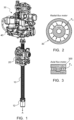
Figure 1 shows a standard THSA. -
Figure 2 shows, schematically, the flux direction of a radial flux motor such as used in an actuator like that shown inFig. 1 . -
Figure 3 shows, schematically, the flux direction of an axial flux motor such as used in an actuator like that shown inFig. 4 . -
Figure 4 shows an actuator according to the present disclosure. -
Figure 5 is a schematic view of a THSA as known in the art. -
Figure 6 is a schematic view of an actuator according to the disclosure. - With reference to
Fig. 1 , a typical known flight control actuator of the trimmable horizontal stabiliser actuator (THSA) type includes a primary load path with ahollow screw 10 which is connected, in use, to the aircraft. The THSA links the aircraft structure to the stabilizer through e.g. upper and lower gimbals. The primary load path further includes anut assembly 20 mounted on thescrew 10. Thenut assembly 20 is connected, in use, to the stabiliser of the aircraft. A secondary load path is typically provided by means of a tie bar (not shown) which is within thescrew 10 and is connected to the structure of the aircraft. The THSA and the load paths through the screw are known and will not be described further. Thescrew 10 is rotationally driven by means of aradial flux motor 30 mounted to thescrew 10. Thescrew 10 may be a ballscrew such that movement of saidnut assembly 20 is caused due to the presence of balls (not shown) between thenut assembly 20 and the screw shaft 10.Thescrew shaft 10 is rotated by means of one or twomotors 30 that drive areduction gear assembly 40, which gears cause saidscrew shaft 10 to rotate. Upon rotation of thescrew shaft 10, thenut 20 moves along the screw shaft. - The
screw 10 defines an axis A along its length from the end connected 12 to the aircraft and the opposite end to which themotor 30 is attached via the gears. Theradial motor 30 is mounted such that the flux, which is generated radially between the motor stator and the motor rotor, as indicated by arrows FR inFig. 2 , is perpendicular to the screw axis A. - As is known, a radial flux motor includes a rotor and a stator arranged coaxially. Permanent magnets on the stator or rotor interact with coils on the other of the rotor or stator to generate a radial flux FR as seen in
Fig. 2 . The flux is therefore generated perpendicular to the axis of rotation A. - Because a radial flux motor is a high speed, low torque motor, and because the trim or other surface to be moved by the actuator requires a high torque and low speed,
gears 40 are required to increase the torque generated by themotor 30 to a higher torque. - Typically, a THSA requires two such radial flux motors to provide redundancy (torque summing).
- An actuator of this type also typically includes a no-
back brake mechanism 50 as mentioned above. - The arrangement of the radial flux motors and the
gear system 40, mounted around thescrew 10, provides a relatively bulky design. - In order to provide a smaller, simpler actuator, according to the present invention, the radial flux motor and gears are replaced by an
axial flux motor 300. The geometry of an axial flux motor is different from that of a radial flux motor and the flux is generated parallel to the axis of rotation (as shown by the arrows FA inFig. 3 ). Although axial flux motors per se are known, they have not previously been used in commercial applications due to complexity and cost of manufacturing. In recent times, however, advances in materials such as soft magnetic composite (SMC) materials has made it more feasible to use axial flux motors in practical designs. - In an axial flux motor, the rotor is axially spaced from the stator. Having the rotor on the motor outer diameter means that the motor can produce greater torque for the same or smaller overall motor footprint. The axial flux motor used in the actuator of this disclosure is mounted to the screw shaft 100 such that the flux generated by the motor is parallel to the screw shaft axis A.
- As the axial flux motor has a greater torque, it can directly drive the screw shaft 100 without the need for gears. This together with the relatively flat profile of the axial motor reduces the overall footprint compared to the radial motor arrangement, as can be seen from
Fig. 4 as well asFig. 6 when compared toFig. 5 . - The operation of the nut 200 on the screw shaft 100 is the same as for the conventional THSA and will not be described further.
- As with the known designs, the actuator of the disclosure may include motor position sensors. In the present case, these may also detect the ballscrew position thus avoiding the need for resolvers.
- A no-back brake NBB 500 may also be provided as in the known system.
- The example shown in
Fig. 6 has twoaxial motors
Claims (9)
- A linear actuator comprising:a screw shaft (100);a nut assembly (200) mounted to the screw shaft to move linearly along the screw shaft as the screw shaft is rotated; anda motor (300a) to rotate the screw shaft, wherein the motor is an axial flux motor.
- A linear actuator as claimed in claim 1, further comprising a no-back brake (500) to prevent back-rotation of the motor (300).
- A linear actuator as claimed in claim 1 or 2, further comprising a second motor (300b) to provide redundancy for the motor (300a).
- A linear actuator as claimed in claim 1 or 2, wherein the motor (300a) is a single, fault tolerant axial flux motor.
- A linear actuator as claimed in claim 1, 2 or 3, further comprising a motor position sensor.
- A linear actuator as claimed in any preceding claim, further comprising means for connecting the screw shaft to an aircraft part to be moved by the linear actuator.
- A linear actuator as claimed in any preceding claim being a trimmable horizontal stabilisation actuator, THSA, of an aircraft.
- An aircraft having a flight control part and a THSA as claimed in claim 7 for controlling movement of the flight control part.
- The aircraft of claim 8, wherein the flight control part is a horizontal stabilizer.
Priority Applications (3)
| Application Number | Priority Date | Filing Date | Title |
|---|---|---|---|
| EP22306906.3A EP4385886A1 (en) | 2022-12-16 | 2022-12-16 | Trimmable horizontal stabilisation actuator |
| CA3218705A CA3218705A1 (en) | 2022-12-16 | 2023-11-02 | Trimmable horizontal stabilisation actuator |
| US18/538,235 US12486024B2 (en) | 2022-12-16 | 2023-12-13 | Trimmable horizontal stabilisation actuator |
Applications Claiming Priority (1)
| Application Number | Priority Date | Filing Date | Title |
|---|---|---|---|
| EP22306906.3A EP4385886A1 (en) | 2022-12-16 | 2022-12-16 | Trimmable horizontal stabilisation actuator |
Publications (1)
| Publication Number | Publication Date |
|---|---|
| EP4385886A1 true EP4385886A1 (en) | 2024-06-19 |
Family
ID=84887764
Family Applications (1)
| Application Number | Title | Priority Date | Filing Date |
|---|---|---|---|
| EP22306906.3A Pending EP4385886A1 (en) | 2022-12-16 | 2022-12-16 | Trimmable horizontal stabilisation actuator |
Country Status (3)
| Country | Link |
|---|---|
| US (1) | US12486024B2 (en) |
| EP (1) | EP4385886A1 (en) |
| CA (1) | CA3218705A1 (en) |
Citations (4)
| Publication number | Priority date | Publication date | Assignee | Title |
|---|---|---|---|---|
| EP3611403A1 (en) * | 2018-08-14 | 2020-02-19 | Hamilton Sundstrand Corporation | Jam-tolerant electric linear actuator |
| EP3677503A2 (en) * | 2019-01-02 | 2020-07-08 | Airbus Operations Limited | Actuator assembly for moving an aircraft wing tip device |
| US11253057B2 (en) * | 2018-08-09 | 2022-02-22 | Reactive Reality Gmbh | Adjustable lifting column and adjustable table system |
| US20220185448A1 (en) * | 2020-12-16 | 2022-06-16 | The Boeing Company | Trim actuators for horizontal stabilizers and methods of controlling horizontal stabilizers |
Family Cites Families (2)
| Publication number | Priority date | Publication date | Assignee | Title |
|---|---|---|---|---|
| US8072172B2 (en) | 2008-12-17 | 2011-12-06 | Honeywell International Inc. | Redundant electromechanical actuator for control surfaces |
| US11454305B1 (en) * | 2021-06-11 | 2022-09-27 | Whippany Actuation Systems Llc | Jam free linear actuation system implementing a mechanical disengagement mechanism and process thereof |
-
2022
- 2022-12-16 EP EP22306906.3A patent/EP4385886A1/en active Pending
-
2023
- 2023-11-02 CA CA3218705A patent/CA3218705A1/en active Pending
- 2023-12-13 US US18/538,235 patent/US12486024B2/en active Active
Patent Citations (4)
| Publication number | Priority date | Publication date | Assignee | Title |
|---|---|---|---|---|
| US11253057B2 (en) * | 2018-08-09 | 2022-02-22 | Reactive Reality Gmbh | Adjustable lifting column and adjustable table system |
| EP3611403A1 (en) * | 2018-08-14 | 2020-02-19 | Hamilton Sundstrand Corporation | Jam-tolerant electric linear actuator |
| EP3677503A2 (en) * | 2019-01-02 | 2020-07-08 | Airbus Operations Limited | Actuator assembly for moving an aircraft wing tip device |
| US20220185448A1 (en) * | 2020-12-16 | 2022-06-16 | The Boeing Company | Trim actuators for horizontal stabilizers and methods of controlling horizontal stabilizers |
Non-Patent Citations (2)
| Title |
|---|
| DUMAS F ET AL: "Design and comparison of two multi-disc permanent magnet motors for aeronautical application", ELECTRICAL MACHINES (ICEM), 2012 XXTH INTERNATIONAL CONFERENCE ON, IEEE, 2 September 2012 (2012-09-02), pages 647 - 652, XP032464785, ISBN: 978-1-4673-0143-5, DOI: 10.1109/ICELMACH.2012.6349938 * |
| SAYED EHAB ET AL: "Review of Electric Machines in More-/Hybrid-/Turbo-Electric Aircraft", IEEE TRANSACTIONS ON TRANSPORTATION ELECTRIFICATION, IEEE, vol. 7, no. 4, 15 June 2021 (2021-06-15), pages 2976 - 3005, XP011880912, DOI: 10.1109/TTE.2021.3089605 * |
Also Published As
| Publication number | Publication date |
|---|---|
| US20240199198A1 (en) | 2024-06-20 |
| US12486024B2 (en) | 2025-12-02 |
| CA3218705A1 (en) | 2024-06-16 |
Similar Documents
| Publication | Publication Date | Title |
|---|---|---|
| US5214972A (en) | Fault-tolerant linear electromechanical actuator | |
| CN104619590B (en) | Control Surface Drive Components | |
| US7610828B2 (en) | Flight control surface actuator assembly including a free trial mechanism | |
| US9162751B2 (en) | Apparatus for use on an aircraft | |
| EP3631243B1 (en) | Fault-tolerant electromechanical linear actuator | |
| US10066715B2 (en) | Fail-safe electromechanical actuator | |
| US7828245B2 (en) | Dual motor dual concentric valve | |
| EP2415669B1 (en) | Control system | |
| EP1927543B1 (en) | Electro-mechanical linear actuator | |
| EP1793477B1 (en) | Fault-tolerant electro-mechanical actuator having a torque sensing control system | |
| EP4206490B1 (en) | A trim horizontal stabiliser actuator comprising an electromechanical linear actuator | |
| US12486024B2 (en) | Trimmable horizontal stabilisation actuator | |
| US20250146563A1 (en) | Fault tolerant rotary ema | |
| US12449025B2 (en) | Linear actuator | |
| CN117897334A (en) | Non-stuck linear actuation system and process implementing mechanical disengagement mechanism | |
| EP3330570B1 (en) | Control system for an actuator | |
| CN1980010B (en) | Fault-tolerant electromechanical actuator | |
| BR102023023713A2 (en) | LINEAR ACTUATOR, AND, AIRCRAFT |
Legal Events
| Date | Code | Title | Description |
|---|---|---|---|
| PUAI | Public reference made under article 153(3) epc to a published international application that has entered the european phase |
Free format text: ORIGINAL CODE: 0009012 |
|
| STAA | Information on the status of an ep patent application or granted ep patent |
Free format text: STATUS: THE APPLICATION HAS BEEN PUBLISHED |
|
| AK | Designated contracting states |
Kind code of ref document: A1 Designated state(s): AL AT BE BG CH CY CZ DE DK EE ES FI FR GB GR HR HU IE IS IT LI LT LU LV MC ME MK MT NL NO PL PT RO RS SE SI SK SM TR |
|
| STAA | Information on the status of an ep patent application or granted ep patent |
Free format text: STATUS: REQUEST FOR EXAMINATION WAS MADE |
|
| 17P | Request for examination filed |
Effective date: 20241219 |
|
| STAA | Information on the status of an ep patent application or granted ep patent |
Free format text: STATUS: EXAMINATION IS IN PROGRESS |
|
| 17Q | First examination report despatched |
Effective date: 20251024 |