EP4385874A1 - Bicycle power transmission device - Google Patents
Bicycle power transmission device Download PDFInfo
- Publication number
- EP4385874A1 EP4385874A1 EP23209381.5A EP23209381A EP4385874A1 EP 4385874 A1 EP4385874 A1 EP 4385874A1 EP 23209381 A EP23209381 A EP 23209381A EP 4385874 A1 EP4385874 A1 EP 4385874A1
- Authority
- EP
- European Patent Office
- Prior art keywords
- pair
- rotors
- power transmission
- transmission device
- rotor
- Prior art date
- Legal status (The legal status is an assumption and is not a legal conclusion. Google has not performed a legal analysis and makes no representation as to the accuracy of the status listed.)
- Pending
Links
- 230000005540 biological transmission Effects 0.000 title claims abstract description 56
- 230000000149 penetrating effect Effects 0.000 claims description 4
- 230000008878 coupling Effects 0.000 claims description 2
- 238000010168 coupling process Methods 0.000 claims description 2
- 238000005859 coupling reaction Methods 0.000 claims description 2
- 230000004308 accommodation Effects 0.000 description 19
- 230000002093 peripheral effect Effects 0.000 description 5
- XEEYBQQBJWHFJM-UHFFFAOYSA-N Iron Chemical compound [Fe] XEEYBQQBJWHFJM-UHFFFAOYSA-N 0.000 description 4
- 239000004918 carbon fiber reinforced polymer Substances 0.000 description 4
- 230000004048 modification Effects 0.000 description 4
- 238000012986 modification Methods 0.000 description 4
- 229910052742 iron Inorganic materials 0.000 description 2
- 229910001220 stainless steel Inorganic materials 0.000 description 2
- 239000010935 stainless steel Substances 0.000 description 2
- 230000006835 compression Effects 0.000 description 1
- 238000007906 compression Methods 0.000 description 1
Images


Classifications
-
- B—PERFORMING OPERATIONS; TRANSPORTING
- B62—LAND VEHICLES FOR TRAVELLING OTHERWISE THAN ON RAILS
- B62M—RIDER PROPULSION OF WHEELED VEHICLES OR SLEDGES; POWERED PROPULSION OF SLEDGES OR SINGLE-TRACK CYCLES; TRANSMISSIONS SPECIALLY ADAPTED FOR SUCH VEHICLES
- B62M1/00—Rider propulsion of wheeled vehicles
- B62M1/36—Rider propulsion of wheeled vehicles with rotary cranks, e.g. with pedal cranks
-
- B—PERFORMING OPERATIONS; TRANSPORTING
- B62—LAND VEHICLES FOR TRAVELLING OTHERWISE THAN ON RAILS
- B62M—RIDER PROPULSION OF WHEELED VEHICLES OR SLEDGES; POWERED PROPULSION OF SLEDGES OR SINGLE-TRACK CYCLES; TRANSMISSIONS SPECIALLY ADAPTED FOR SUCH VEHICLES
- B62M1/00—Rider propulsion of wheeled vehicles
- B62M1/10—Rider propulsion of wheeled vehicles involving devices which enable the mechanical storing and releasing of energy occasionally, e.g. arrangement of flywheels
- B62M1/105—Rider propulsion of wheeled vehicles involving devices which enable the mechanical storing and releasing of energy occasionally, e.g. arrangement of flywheels using elastic elements
-
- B—PERFORMING OPERATIONS; TRANSPORTING
- B62—LAND VEHICLES FOR TRAVELLING OTHERWISE THAN ON RAILS
- B62M—RIDER PROPULSION OF WHEELED VEHICLES OR SLEDGES; POWERED PROPULSION OF SLEDGES OR SINGLE-TRACK CYCLES; TRANSMISSIONS SPECIALLY ADAPTED FOR SUCH VEHICLES
- B62M3/00—Construction of cranks operated by hand or foot
-
- B—PERFORMING OPERATIONS; TRANSPORTING
- B62—LAND VEHICLES FOR TRAVELLING OTHERWISE THAN ON RAILS
- B62M—RIDER PROPULSION OF WHEELED VEHICLES OR SLEDGES; POWERED PROPULSION OF SLEDGES OR SINGLE-TRACK CYCLES; TRANSMISSIONS SPECIALLY ADAPTED FOR SUCH VEHICLES
- B62M9/00—Transmissions characterised by use of an endless chain, belt, or the like
-
- B—PERFORMING OPERATIONS; TRANSPORTING
- B62—LAND VEHICLES FOR TRAVELLING OTHERWISE THAN ON RAILS
- B62M—RIDER PROPULSION OF WHEELED VEHICLES OR SLEDGES; POWERED PROPULSION OF SLEDGES OR SINGLE-TRACK CYCLES; TRANSMISSIONS SPECIALLY ADAPTED FOR SUCH VEHICLES
- B62M3/00—Construction of cranks operated by hand or foot
- B62M3/06—Construction of cranks operated by hand or foot with elliptical or other non-circular rotary movement
Definitions
- the present invention relates to a bicycle power transmission device.
- Japan Laid-open Patent Application Publication No. 2020-059347 discloses a power transmission device that a pair of output plates are disposed to interpose an input plate therebetween in an axial direction. Besides, elastic members elastically couple the input plate and the pair output plates. Furthermore, fixation pins, provided for coupling the pair of output plates, contact with end portions of stopper holes, respectively, whereby relative rotation between the input plate and the pair of first and second output plates is restricted to a predetermined angular range.
- a bicycle power transmission device includes a first rotor, a pair of second rotors, an elastic member, and a stopper member.
- the first rotor is disposed to be rotatable.
- the pair of second rotors is disposed to interpose the first rotor therebetween in an axial direction.
- the pair of second rotors is attached to each other so as to be detachable from each other.
- the elastic member elastically couples the first rotor and the pair of second rotors.
- the stopper member is attached to the pair of second rotors so as to be disposed therebetween.
- the first rotor includes a stopper surface opposed to the stopper member at an interval in a rotational direction.
- a user is enabled to detach the pair of second rotors from each other and then to, for instance, replace the stopper member and/or the elastic member by a desired type of stopper member and/or a desired type of elastic member.
- the bicycle power transmission device can be made suitable for the user.
- a bicycle power transmission device relates to the bicycle power transmission device according to the first aspect, and further includes a plurality of bolts.
- the plurality of bolts are configured to attach the pair of second rotors to each other so as to make the pair of second rotors detachable from each other.
- the stopper member includes a through hole penetrating therethrough in the axial direction. Each of the plurality of bolts extends to penetrate the through hole.
- a bicycle power transmission device relates to the bicycle power transmission device according to the first or second aspect, and further includes a sprocket part and a crank arm.
- the sprocket part is provided on one of the pair of second rotors.
- the crank arm is configured to be unitarily rotated with the first rotor.
- a bicycle power transmission device relates to the bicycle power transmission device according to the fourth aspect and is configured as follows.
- the crank arm is spline-coupled to the inner flanged portion.
- a bicycle power transmission device relates to the bicycle power transmission device according to any of the first to seventh aspects and is configured as follows.
- the stopper member is selected from a plurality of types of stopper members different in circumferential dimension from each other.
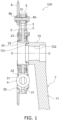
- FIG. 1 is a cross-sectional view of a power transmission device 100.
- the power transmission device 100 includes a first rotor 2, a pair of second rotors 3, a plurality of elastic members 4, a plurality of stopper members 5, a sprocket part 6, a crank arm 7, a plurality of bolts 8a, and a plurality of nuts 8b.
- the power transmission device 100 is disposed to be rotatable about the rotational axis O.
- the power transmission device 100 is installed in a bicycle.
- the power transmission device 100 is installed in a type of bicycle driven only by a human power without including an electric motor or so forth.
- the power transmission device 100 may be installed in another type of bicycle including an electric motor.
- the bicycle may have two modes: an electric mode for driving the bicycle only by the electric motor and a human power mode for driving the bicycle only by the human power.
- the bicycle may have an assist mode for driving the bicycle by both the electric motor and the human power, or alternatively, may not have the assist mode.
- the power transmission device 100 is configured to transmit a torque, inputted to a pedal (omitted in illustration) attached to a distal end of the crank arm 7, to a drive wheel (omitted in illustration).
- FIG. 2 is a front view of the power transmission device 100 from which some of the elastic members 4, the crank arm 7, and one of the pair of second rotors 3 are detached. As shown in FIG. 2 , the power transmission device 100 is configured to be rotated in a rotational direction R (clockwise in FIG. 2 ).
- the first rotor 2 includes a plurality of first accommodation portions 21. It should be noted that in the present preferred embodiment, the first rotor 2 includes three first accommodation portions 21. The first accommodation portions 21 penetrate the first rotor 2 in the axial direction. The first accommodation portions 21 are disposed at intervals in the circumferential direction. The first accommodation portions 21 are disposed at equal intervals.
- the first rotor 2 is disposed to be rotatable in the rotational direction R.
- the first rotor 2 is a member to which the torque is inputted from the crank arm 7.
- the first rotor 2 is configured to be unitarily rotated with the crank arm 7.
- the first rotor 2 includes a hub portion 22, an outer flanged portion 23, and an inner flanged portion 24.
- the hub portion 22 is made in shape of a cylinder extending in the axial direction.
- a crankshaft (omitted in illustration) extends inside the hub portion 22.
- the outer flanged portion 23 extends radially outward from the hub portion 22.
- the outer flanged portion 23 is provided with the first accommodation portions 21.
- the outer flanged portion 23 is provided on the axial middle of the hub portion 22.
- the inner flanged portion 24 extends radially inward from the hub portion 22.
- the inner flanged portion 24 includes a spline hole 241 on the inner peripheral surface thereof.
- the inner flanged portion 24 is provided on one of the axial ends of the hub portion 22.
- the inner flanged portion 24 is different in axial position from the outer flanged portion 23. In other words, the inner flanged portion 24 does not overlap with the outer flanged portion 23 in a radial view.
- the first rotor 2 includes a plurality of stopper surfaces 25.
- the first rotor 2 includes a plurality of cutout portions 26.
- the cutout portions 26 are disposed at intervals in the circumferential direction. Each cutout portion 26 is disposed between each adjacent pair of first accommodation portions 21 in the circumferential direction. Each cutout portion 26 is opened radially outward.
- a surface facing the rotational direction R serves as each stopper surface 25.
- Each stopper surface 25 faces the rotational direction R. Each stopper surface 25 is opposed to each stopper member 5 at an interval in the rotational direction.
- the first rotor 2 can be made of, for instance, iron, stainless steel, carbon fiber reinforced plastics (CFRP), or so forth.
- the pair of second rotors 3 is disposed to be rotatable in the rotational direction R.
- the pair of second rotors 3 is disposed to be rotatable relative to the first rotor 2.
- the pair of second rotors 3 is substantially identical in configuration to each other; hence, detailed explanation will be hereinafter made for one of the pair of second rotors 3 but will be omitted for the other.
- the pair of second rotors 3 is disposed away from each other at an interval in the axial direction.
- the first rotor 2 is disposed between the pair of second rotors 3.
- the pair of second rotors 3 is disposed to interpose the first rotor 2 therebetween in the axial direction.
- the outer flanged portion 23 of the first rotor 2 is disposed between the pair of second rotors 3 in the axial direction.
- the pair of second rotors 3 is attached to each other by the plural bolts 8a and the plural nuts 8b so as to be detachable from each other. Because of this, the pair of second rotors 3 is unitarily rotated with each other.
- the bolts 8a are configured to attach the pair of second rotors 3 to each other so as to make the pair of second rotors 3 detachable from each other. Specifically, each bolt 8a is screwed into each nut 8b, while penetrating each of holes provided in each of the pair of second rotors 3 in the axial direction. When each bolt 8a is unscrewed from each nut 8b, the pair of second rotors 3 is made detachable from each other. Then, when each bolt 8a is screwed into each nut 8b, the pair of second rotors 3, detached from each other, is again made easily attachable to each other.
- the stopper members 5 are disposed between the pair of second rotors 3 in the axial direction.
- the stopper members 5 are disposed in the cutout portions 26 of the first rotor 2, respectively.
- the stopper members 5 are attached to the pair of second rotors 3 so as to be unitarily rotated therewith.
- a torsion angle i.e., an angle of torsion (relative rotation) between the first rotor 2 and the pair of second rotors 3
- the stopper surfaces 25 contact with the stopper members 5, respectively.
- the first rotor 2 is restricted from rotating relative to the pair of second rotors 3 any further from the position. In other words, the first rotor 2 is rotated relative to the pair of second rotors 3 until the stopper members 5 contact with the stopper surfaces 25, respectively.
- the first rotor 2 is unitarily rotated with the pair of second rotors 3 after the stopper members 5 contact with the stopper surfaces 25, respectively.
- the torsion angle between the first rotor 2 and the pair of second rotors 3 is maximized (hereinafter referred to as "maximum torsion angle") when the stopper surfaces 25 contact with the stopper members 5, respectively.
- the torsion angle between the first rotor 2 and the pair of second rotors 3 is 0 degrees when the torque is not being inputted to the power transmission device 100.
- each stopper member 5 is attached to the pair of second rotors 3 so as to be replaceable by any suitable type of stopper members.
- each stopper member 5 includes a through hole 51 penetrating therethrough in the axial direction.
- Each bolt 8a extends to penetrate inside the through hole 51 of each stopper member 5.
- a type of stopper members is selectable as the stopper members 5 used in the power transmission device 100 from, for instance, a plurality of types of stopper members different in circumferential dimension from each other.
- a type of stopper members is selectable as the stopper members 5 from a plurality of types of stopper members different in outer diameter from each other.
- the second rotor 3 has a disc shape and includes a through hole in a middle part thereof.
- the hub portion 22 of the first rotor 2 extends inside the through hole of the second rotor 3 in the axial direction.
- the second rotor 3 includes a plurality of second accommodation portions 31. It should be noted that in the present preferred embodiment, the second rotor 3 includes three second accommodation portions 31. The second accommodation portions 31 are disposed at intervals in the circumferential direction.
- Each second accommodation portion 31 penetrates the second rotor 3 in the axial direction. Each second accommodation portion 31 extends in the circumferential direction.
- the second accommodation portions 31 are substantially disposed on an identical imaginary circle.
- the second accommodation portions 31 are disposed to be axially opposed to the first accommodation portions 21, respectively. Put differently, in an axial view, the second accommodation portions 31 are disposed to overlap with the first accommodation portions 21, respectively.
- the second rotor 3 includes first cut-and-raised portions 32 and second cut-and-raised portions 33.
- the first and second cut-and-raised portions 32 and 33 are formed by cutting and raising the second rotor 3 in part.
- Each first cut-and-raised portion 32 is disposed radially outside each elastic member 4.
- Each second cut-and-raised portion 33 is disposed radially inside each elastic member 4.
- Each pair of first and second cut-and-raised portions 32 and 33 is configured to restrict axial movement of each elastic member 4.
- the second rotor 3 can be made of, for instance, iron, stainless steel, carbon fiber reinforced plastics (CFRP), or so forth.
- the sprocket part 6 is provided on one of the pair of second rotors 3.
- the sprocket part 6 is provided as a member separated from the one of the pair of second rotors 3 and is attached to the one of the pair of second rotors 3 by the bolts 8a and the nuts 8b.
- the sprocket part 6 is unitarily rotated with the pair of second rotors 3.
- the sprocket part 6 includes a plurality of teeth on the outer peripheral end thereof.
- a chain (omitted in illustration) is wrapped around the sprocket part 6, whereby the torque is transmitted from the sprocket part 6 to the drive wheel (omitted in illustration) through the chain and so forth.
- the elastic members 4 are, for instance, coil springs.
- the elastic members 4 elastically couple the first rotor 2 and the pair of second rotors 3 in the rotational direction. In other words, the torque, outputted from the first rotor 2, is transmitted to the pair of second rotors 3 through the elastic members 4.
- the elastic members 4 are rotated together with the first rotor 2 and the pair of second rotors 3.
- torsion relative rotation
- the elastic members 4 are not being compressed, torsion is not caused between the first rotor 2 and the pair of second rotors 3; hence, the torsion angle is 0 degrees.
- the crank arm 7 is configured to be unitarily rotated with the first rotor 2. In other words, the crank arm 7 is disposed to be rotatable about the rotational axis O.
- the crank arm 7 is attached to the inner flanged portion 24 of the first rotor 2.
- the crank arm 7 is configured to be spline-coupled to the inner flanged portion 24.
- the crank arm 7 includes an arm body 71 and an attachment portion 72.
- the arm body 71 extends in a radial direction.
- the attachment portion 72 extends from one of both ends of the arm body 71 in the axial direction. It should be noted that the pedal (omitted in illustration) is attached to the other of both ends of the arm body 71.
- the outer diameter of the attachment portion 72 is lesser in a distal end 721 than in the remaining part thereof.
- the distal end 721 is spline-coupled to the inner flanged portion 24. Besides, the distal end 721 penetrates the inner flanged portion 24 in the axial direction. Then, the distal end 721 is fixed to the inner flanged portion 24 by swaging. When described in detail, the distal end 721 and the inner flanged portion 24 are firmly attached to each other by swaging of the distal end 721.
- a part of the distal end 721, protruding from the inner flanged portion 24, is enlarged in outer diameter by swaging; namely, the outer diameter of the protruding part is made greater than the inner diameter of the inner flanged portion 24.
- the attachment portion 72 includes an attachment hole 722.
- the attachment hole 722 has a rectangular shape in the axial view.
- the crankshaft (omitted in illustration) is fitted to the attachment hole 722, whereby the crank arm 7 is unitarily rotated with the crankshaft.
- the action of the power transmission device 100 configured as described above will be explained.
- a torque is inputted to the first rotor 2 through the crank arm 7 by pedaling of a user
- the first rotor 2 is rotated in the rotational direction R.
- the torque is transmitted from the first rotor 2 to the pair of second rotors 3 through the elastic members 4.
- the pair of second rotors 3 is rotated in the rotational direction R, whereby the torque is transmitted to the drive wheel.
- the torsion angle between the first rotor 2 and the pair of second rotors 3 reaches a predetermined angle by compression of the elastic members 4, the stopper surfaces 25 contact with the stopper members 5, respectively. As a result, the first rotor 2 and the pair of second rotors 3 are unitarily rotated.
- the maximum torsion angle can be changed by replacement of the stopper members 5. For example, when the stopper members 5 are replaced by a type of stopper members having a greater outer diameter than the stopper members 5, the maximum torsion angle can be made small. Contrarily, when the stopper members 5 are replaced by another type of stopper members having a lesser outer diameter than the stopper members 5, the maximum torsion angle can be made large. It should be noted that in the power transmission device 100, the torsion angle is configured to be maximized before the elastic members 4 are fully compressed.
- Each elastic member 4 is preferably set to have a spring constant, by which the torsion angle between the first rotor 2 and the pair of second rotors 3 is maximized when a torque of 100 N ⁇ m or less is inputted to the first rotor 2.
- each elastic member 4 is preferably set to have a spring constant, by which the torsion angle between the first rotor 2 and the pair of second rotors 3 is maximized when a torque of 20 N ⁇ m or greater is inputted to the first rotor 2.
- maximum torque the torque, inputted to the first rotor 2 when the torsion angle is maximized, will be referred to as "maximum torque”.
- a variety of types of elastic members are prepared as options for the elastic members 4.
- the variety of types of elastic members are set to be different in spring constant from each other so as to maximize the torsion angle when the magnitude (N m) of the maximum torque is approximately each of the following values (albeit not particularly limited thereto): 90, 80, 70, 60, 50, 40, and 30. Then, any of the variety of types of elastic members may be configured to be arbitrarily selected by the user as the elastic members 4.
Landscapes
- Engineering & Computer Science (AREA)
- Chemical & Material Sciences (AREA)
- Combustion & Propulsion (AREA)
- Transportation (AREA)
- Mechanical Engineering (AREA)
- Transmission Devices (AREA)
Abstract
Description
- This application is based on and claims the priority benefit of
Japanese application 2022-198151 filed on December 12, 2022 - The present invention relates to a bicycle power transmission device.
- There has been disclosed a type of bicycle power transmission device configured to be capable of widening a torsion angle, i.e., an angle of torsion (relative rotation) between an input plate and an output plate. For example,
Japan Laid-open Patent Application Publication No. 2020-059347 - It is an object of the present invention to provide a bicycle power transmission device suitable for a user.
- A bicycle power transmission device according to a first aspect includes a first rotor, a pair of second rotors, an elastic member, and a stopper member. The first rotor is disposed to be rotatable. The pair of second rotors is disposed to interpose the first rotor therebetween in an axial direction. The pair of second rotors is attached to each other so as to be detachable from each other. The elastic member elastically couples the first rotor and the pair of second rotors. The stopper member is attached to the pair of second rotors so as to be disposed therebetween. The first rotor includes a stopper surface opposed to the stopper member at an interval in a rotational direction.
- According to this configuration, a user is enabled to detach the pair of second rotors from each other and then to, for instance, replace the stopper member and/or the elastic member by a desired type of stopper member and/or a desired type of elastic member. As a result, the bicycle power transmission device can be made suitable for the user.
- A bicycle power transmission device according to a second aspect relates to the bicycle power transmission device according to the first aspect, and further includes a plurality of bolts. The plurality of bolts are configured to attach the pair of second rotors to each other so as to make the pair of second rotors detachable from each other. The stopper member includes a through hole penetrating therethrough in the axial direction. Each of the plurality of bolts extends to penetrate the through hole.
- A bicycle power transmission device according to a third aspect relates to the bicycle power transmission device according to the first or second aspect, and further includes a sprocket part and a crank arm. The sprocket part is provided on one of the pair of second rotors. The crank arm is configured to be unitarily rotated with the first rotor.
- A bicycle power transmission device according to a fourth aspect relates to the bicycle power transmission device according to the third aspect and is configured as follows. The first rotor includes a hub portion, an outer flanged portion, and an inner flanged portion. The hub portion extends in the axial direction. The hub portion has a tubular shape. The outer flanged portion extends radially outward from the hub portion. The inner flanged portion extends radially inward from the hub portion. The crank arm is attached to the inner flanged portion.
- A bicycle power transmission device according to a fifth aspect relates to the bicycle power transmission device according to the fourth aspect and is configured as follows. The crank arm is spline-coupled to the inner flanged portion.
- A bicycle power transmission device according to a sixth aspect relates to the bicycle power transmission device according to the fourth or fifth aspect and is configured as follows. The crank arm includes an arm body and an attachment portion. The arm body extends in a radial direction. The attachment portion extends from an end of the arm body in the axial direction. The attachment portion penetrates inside the inner flanged portion. The attachment portion is swaged at a distal end thereof to the inner flanged portion.
- A bicycle power transmission device according to a seventh aspect relates to the bicycle power transmission device according to any of the first to sixth aspects and is configured as follows. The stopper member is attached to the pair of second rotors so as to be replaceable by another stopper member.
- A bicycle power transmission device according to a eighth aspect relates to the bicycle power transmission device according to any of the first to seventh aspects and is configured as follows. The stopper member is selected from a plurality of types of stopper members different in circumferential dimension from each other.
- Overall, according to the present invention, it is made possible to provide a bicycle power transmission device suitable for a user.
-
-
FIG. 1 is a cross-sectional view of a power transmission device. -
FIG. 2 is a front view of the power transmission device. -
FIG. 3 is a cross-sectional view of a power transmission device according to a modification. -
FIG. 4 is a front view of a power transmission device according to another modification. - A bicycle power transmission device (hereinafter simply referred to as "power transmission device" on an as-needed basis) according to the present preferred embodiment will be hereinafter explained with reference to drawings. It should be noted that in the following explanation, the term "axial direction" refers to an extending direction of a rotational axis O of the power transmission device. On the other hand, the term "circumferential direction" refers to a circumferential direction of an imaginary circle about the rotational axis O, whereas the term "radial direction" refers to a radial direction of the imaginary circle about the rotational axis O. Yet on the other hand, the term "rotational direction" refers to a direction in which the power transmission device is rotated in traveling of a bicycle.
-
FIG. 1 is a cross-sectional view of apower transmission device 100. As shown inFIG. 1 , thepower transmission device 100 includes afirst rotor 2, a pair ofsecond rotors 3, a plurality ofelastic members 4, a plurality ofstopper members 5, a sprocket part 6, acrank arm 7, a plurality ofbolts 8a, and a plurality ofnuts 8b. Thepower transmission device 100 is disposed to be rotatable about the rotational axis O. - The
power transmission device 100 is installed in a bicycle. For example, thepower transmission device 100 is installed in a type of bicycle driven only by a human power without including an electric motor or so forth. It should be noted that thepower transmission device 100 may be installed in another type of bicycle including an electric motor. In this case, for instance, the bicycle may have two modes: an electric mode for driving the bicycle only by the electric motor and a human power mode for driving the bicycle only by the human power. It should be noted that the bicycle may have an assist mode for driving the bicycle by both the electric motor and the human power, or alternatively, may not have the assist mode. Thepower transmission device 100 is configured to transmit a torque, inputted to a pedal (omitted in illustration) attached to a distal end of thecrank arm 7, to a drive wheel (omitted in illustration). -
FIG. 2 is a front view of thepower transmission device 100 from which some of theelastic members 4, thecrank arm 7, and one of the pair ofsecond rotors 3 are detached. As shown inFIG. 2 , thepower transmission device 100 is configured to be rotated in a rotational direction R (clockwise inFIG. 2 ). - As shown in
FIGS. 1 and2 , thefirst rotor 2 includes a plurality offirst accommodation portions 21. It should be noted that in the present preferred embodiment, thefirst rotor 2 includes threefirst accommodation portions 21. Thefirst accommodation portions 21 penetrate thefirst rotor 2 in the axial direction. Thefirst accommodation portions 21 are disposed at intervals in the circumferential direction. Thefirst accommodation portions 21 are disposed at equal intervals. - The
first rotor 2 is disposed to be rotatable in the rotational direction R. Thefirst rotor 2 is a member to which the torque is inputted from thecrank arm 7. Thefirst rotor 2 is configured to be unitarily rotated with thecrank arm 7. - The
first rotor 2 includes ahub portion 22, an outerflanged portion 23, and an innerflanged portion 24. Thehub portion 22 is made in shape of a cylinder extending in the axial direction. When thepower transmission device 100 is installed in the bicycle, a crankshaft (omitted in illustration) extends inside thehub portion 22. - The outer
flanged portion 23 extends radially outward from thehub portion 22. The outerflanged portion 23 is provided with thefirst accommodation portions 21. The outerflanged portion 23 is provided on the axial middle of thehub portion 22. - The inner
flanged portion 24 extends radially inward from thehub portion 22. The innerflanged portion 24 includes aspline hole 241 on the inner peripheral surface thereof. The innerflanged portion 24 is provided on one of the axial ends of thehub portion 22. The innerflanged portion 24 is different in axial position from the outerflanged portion 23. In other words, the innerflanged portion 24 does not overlap with the outerflanged portion 23 in a radial view. - The
first rotor 2 includes a plurality of stopper surfaces 25. When described in detail, thefirst rotor 2 includes a plurality ofcutout portions 26. Thecutout portions 26 are disposed at intervals in the circumferential direction. Eachcutout portion 26 is disposed between each adjacent pair offirst accommodation portions 21 in the circumferential direction. Eachcutout portion 26 is opened radially outward. Among inner wall surfaces by which eachcutout portion 26 is defined, a surface facing the rotational direction R serves as eachstopper surface 25. - Each
stopper surface 25 faces the rotational direction R. Eachstopper surface 25 is opposed to eachstopper member 5 at an interval in the rotational direction. - The
first rotor 2 can be made of, for instance, iron, stainless steel, carbon fiber reinforced plastics (CFRP), or so forth. - The pair of
second rotors 3 is disposed to be rotatable in the rotational direction R. The pair ofsecond rotors 3 is disposed to be rotatable relative to thefirst rotor 2. - The pair of
second rotors 3 is substantially identical in configuration to each other; hence, detailed explanation will be hereinafter made for one of the pair ofsecond rotors 3 but will be omitted for the other. - The pair of
second rotors 3 is disposed away from each other at an interval in the axial direction. Thefirst rotor 2 is disposed between the pair ofsecond rotors 3. In other words, the pair ofsecond rotors 3 is disposed to interpose thefirst rotor 2 therebetween in the axial direction. When described in detail, the outerflanged portion 23 of thefirst rotor 2 is disposed between the pair ofsecond rotors 3 in the axial direction. - The pair of
second rotors 3 is attached to each other by theplural bolts 8a and theplural nuts 8b so as to be detachable from each other. Because of this, the pair ofsecond rotors 3 is unitarily rotated with each other. - The
bolts 8a are configured to attach the pair ofsecond rotors 3 to each other so as to make the pair ofsecond rotors 3 detachable from each other. Specifically, eachbolt 8a is screwed into eachnut 8b, while penetrating each of holes provided in each of the pair ofsecond rotors 3 in the axial direction. When eachbolt 8a is unscrewed from eachnut 8b, the pair ofsecond rotors 3 is made detachable from each other. Then, when eachbolt 8a is screwed into eachnut 8b, the pair ofsecond rotors 3, detached from each other, is again made easily attachable to each other. - The
stopper members 5 are disposed between the pair ofsecond rotors 3 in the axial direction. Thestopper members 5 are disposed in thecutout portions 26 of thefirst rotor 2, respectively. Thestopper members 5 are attached to the pair ofsecond rotors 3 so as to be unitarily rotated therewith. - When a torsion angle, i.e., an angle of torsion (relative rotation) between the
first rotor 2 and the pair ofsecond rotors 3, reaches a predetermined angle in traveling of the bicycle, the stopper surfaces 25 contact with thestopper members 5, respectively. Thus, when thestopper members 5 contact with the stopper surfaces 25, respectively, thefirst rotor 2 is restricted from rotating relative to the pair ofsecond rotors 3 any further from the position. In other words, thefirst rotor 2 is rotated relative to the pair ofsecond rotors 3 until thestopper members 5 contact with the stopper surfaces 25, respectively. Then, thefirst rotor 2 is unitarily rotated with the pair ofsecond rotors 3 after thestopper members 5 contact with the stopper surfaces 25, respectively. It should be noted that the torsion angle between thefirst rotor 2 and the pair ofsecond rotors 3 is maximized (hereinafter referred to as "maximum torsion angle") when the stopper surfaces 25 contact with thestopper members 5, respectively. It should be also noted that the torsion angle between thefirst rotor 2 and the pair ofsecond rotors 3 is 0 degrees when the torque is not being inputted to thepower transmission device 100. - The
stopper members 5 are attached to the pair ofsecond rotors 3 so as to be replaceable by any suitable type of stopper members. Specifically, eachstopper member 5 includes a throughhole 51 penetrating therethrough in the axial direction. Eachbolt 8a extends to penetrate inside the throughhole 51 of eachstopper member 5. When eachbolt 8a is unscrewed from eachnut 8b and is detached from the pair ofsecond rotors 3 and eachstopper member 5 and then one of the pair ofsecond rotors 3 is detached from the other, eachstopper member 5 is made replaceable by another stopper member. It should be noted that a type of stopper members is selectable as thestopper members 5 used in thepower transmission device 100 from, for instance, a plurality of types of stopper members different in circumferential dimension from each other. When described in detail, a type of stopper members is selectable as thestopper members 5 from a plurality of types of stopper members different in outer diameter from each other. When eachstopper member 5 is replaced by another stopper member as described above, a distance between eachstopper surface 25 and eachstopper member 5 is changed, whereby the maximum torsion angle between thefirst rotor 2 and the pair ofsecond rotors 3 can be changed. - The
second rotor 3 has a disc shape and includes a through hole in a middle part thereof. Thehub portion 22 of thefirst rotor 2 extends inside the through hole of thesecond rotor 3 in the axial direction. - The
second rotor 3 includes a plurality ofsecond accommodation portions 31. It should be noted that in the present preferred embodiment, thesecond rotor 3 includes threesecond accommodation portions 31. Thesecond accommodation portions 31 are disposed at intervals in the circumferential direction. - Each
second accommodation portion 31 penetrates thesecond rotor 3 in the axial direction. Eachsecond accommodation portion 31 extends in the circumferential direction. Thesecond accommodation portions 31 are substantially disposed on an identical imaginary circle. Thesecond accommodation portions 31 are disposed to be axially opposed to thefirst accommodation portions 21, respectively. Put differently, in an axial view, thesecond accommodation portions 31 are disposed to overlap with thefirst accommodation portions 21, respectively. - The
second rotor 3 includes first cut-and-raisedportions 32 and second cut-and-raisedportions 33. The first and second cut-and-raisedportions second rotor 3 in part. - Each first cut-and-raised
portion 32 is disposed radially outside eachelastic member 4. Each second cut-and-raisedportion 33 is disposed radially inside eachelastic member 4. Each pair of first and second cut-and-raisedportions elastic member 4. - The
second rotor 3 can be made of, for instance, iron, stainless steel, carbon fiber reinforced plastics (CFRP), or so forth. - The sprocket part 6 is provided on one of the pair of
second rotors 3. For example, the sprocket part 6 is provided as a member separated from the one of the pair ofsecond rotors 3 and is attached to the one of the pair ofsecond rotors 3 by thebolts 8a and the nuts 8b. The sprocket part 6 is unitarily rotated with the pair ofsecond rotors 3. The sprocket part 6 includes a plurality of teeth on the outer peripheral end thereof. A chain (omitted in illustration) is wrapped around the sprocket part 6, whereby the torque is transmitted from the sprocket part 6 to the drive wheel (omitted in illustration) through the chain and so forth. - Each of the
elastic members 4 is accommodated in eachfirst accommodation portion 21 and each pair ofsecond accommodation portions 31. Theelastic members 4 are, for instance, coil springs. Theelastic members 4 elastically couple thefirst rotor 2 and the pair ofsecond rotors 3 in the rotational direction. In other words, the torque, outputted from thefirst rotor 2, is transmitted to the pair ofsecond rotors 3 through theelastic members 4. Besides, theelastic members 4 are rotated together with thefirst rotor 2 and the pair ofsecond rotors 3. When the torque is transmitted, theelastic members 4 are compressed, whereby torsion (relative rotation) is caused between thefirst rotor 2 and the pair ofsecond rotors 3. When theelastic members 4 are not being compressed, torsion is not caused between thefirst rotor 2 and the pair ofsecond rotors 3; hence, the torsion angle is 0 degrees. - The
crank arm 7 is configured to be unitarily rotated with thefirst rotor 2. In other words, thecrank arm 7 is disposed to be rotatable about the rotational axis O. Thecrank arm 7 is attached to the innerflanged portion 24 of thefirst rotor 2. When described in detail, thecrank arm 7 is configured to be spline-coupled to the innerflanged portion 24. - The
crank arm 7 includes anarm body 71 and anattachment portion 72. Thearm body 71 extends in a radial direction. Theattachment portion 72 extends from one of both ends of thearm body 71 in the axial direction. It should be noted that the pedal (omitted in illustration) is attached to the other of both ends of thearm body 71. - The outer diameter of the
attachment portion 72 is lesser in adistal end 721 than in the remaining part thereof. Thedistal end 721 is spline-coupled to the innerflanged portion 24. Besides, thedistal end 721 penetrates the innerflanged portion 24 in the axial direction. Then, thedistal end 721 is fixed to the innerflanged portion 24 by swaging. When described in detail, thedistal end 721 and the innerflanged portion 24 are firmly attached to each other by swaging of thedistal end 721. Moreover, a part of thedistal end 721, protruding from the innerflanged portion 24, is enlarged in outer diameter by swaging; namely, the outer diameter of the protruding part is made greater than the inner diameter of the innerflanged portion 24. As a result, thedistal end 721 is prevented from being detached from the innerflanged portion 24; hence, thecrank arm 7 and thefirst rotor 2 can be prevented from moving away from each other to the opposite sides in the axial direction. - The
attachment portion 72 includes anattachment hole 722. Theattachment hole 722 has a rectangular shape in the axial view. The crankshaft (omitted in illustration) is fitted to theattachment hole 722, whereby thecrank arm 7 is unitarily rotated with the crankshaft. - The action of the
power transmission device 100 configured as described above will be explained. First, when a torque is inputted to thefirst rotor 2 through thecrank arm 7 by pedaling of a user, thefirst rotor 2 is rotated in the rotational direction R. Then, the torque is transmitted from thefirst rotor 2 to the pair ofsecond rotors 3 through theelastic members 4. As a result, the pair ofsecond rotors 3 is rotated in the rotational direction R, whereby the torque is transmitted to the drive wheel. - Here, when the torsion angle between the
first rotor 2 and the pair ofsecond rotors 3 reaches a predetermined angle by compression of theelastic members 4, the stopper surfaces 25 contact with thestopper members 5, respectively. As a result, thefirst rotor 2 and the pair ofsecond rotors 3 are unitarily rotated. The maximum torsion angle can be changed by replacement of thestopper members 5. For example, when thestopper members 5 are replaced by a type of stopper members having a greater outer diameter than thestopper members 5, the maximum torsion angle can be made small. Contrarily, when thestopper members 5 are replaced by another type of stopper members having a lesser outer diameter than thestopper members 5, the maximum torsion angle can be made large. It should be noted that in thepower transmission device 100, the torsion angle is configured to be maximized before theelastic members 4 are fully compressed. - Each
elastic member 4 is preferably set to have a spring constant, by which the torsion angle between thefirst rotor 2 and the pair ofsecond rotors 3 is maximized when a torque of 100 N·m or less is inputted to thefirst rotor 2. Besides, eachelastic member 4 is preferably set to have a spring constant, by which the torsion angle between thefirst rotor 2 and the pair ofsecond rotors 3 is maximized when a torque of 20 N·m or greater is inputted to thefirst rotor 2. It should be noted that the torque, inputted to thefirst rotor 2 when the torsion angle is maximized, will be referred to as "maximum torque". Now, a variety of types of elastic members are prepared as options for theelastic members 4. For example, the variety of types of elastic members are set to be different in spring constant from each other so as to maximize the torsion angle when the magnitude (N m) of the maximum torque is approximately each of the following values (albeit not particularly limited thereto): 90, 80, 70, 60, 50, 40, and 30. Then, any of the variety of types of elastic members may be configured to be arbitrarily selected by the user as theelastic members 4. - One preferred embodiment of the present invention has been explained above. However, the present invention is not limited to the above, and a variety of changes can be made without departing from the gist of the present invention. It should be noted that basically speaking, respective modifications to be described are applicable simultaneously.
- (a) In the preferred embodiment described above, the
crank arm 7 is attached to thefirst rotor 2, whereas the sprocket 6 is provided for one of the pair ofsecond rotors 3; however, thepower transmission device 100 is not limited in configuration to this. For example, as shown inFIG. 3 , thecrank arm 7 may be attached to one of the pair ofsecond rotors 3, whereas the sprocket part 6 may be provided for thefirst rotor 2. - (b) In the preferred embodiment described above, the sprocket part 6 is provided as a member separated from one of the pair of
second rotors 3; however, the sprocket part 6 is not limited in configuration to this. For example, the sprocket part 6 may be provided on one of the pair ofsecond rotors 3 so as to be integrated with the outer peripheral end thereof. In other words, the sprocket part 6 may compose a single member together with one of the pair ofsecond rotors 3. When described in detail, one of the pair ofsecond rotors 3 may be provided with a plurality of teeth on the outer peripheral end thereof such that the outer peripheral end provided with the teeth serves as the sprocket part 6. - (c) In the preferred embodiment described above, each
stopper member 5 includes the throughhole 51 penetrated by eachbolt 8a; however, eachstopper member 5 is not limited in configuration to this. For example, eachstopper member 5 may include a pair of screw holes perforated on a one-to-one basis in both surfaces thereof facing the opposite sides in the axial direction. Then, a pair ofbolts 8a may be screwed into the pair of screw holes of eachstopper member 5 from the axially opposite sides so as to fix the pair ofsecond rotors 3 and eachstopper member 5 to each other. It should be noted that the screw holes may be connected to each other so as to be made in form of a single screw hole. - (d) As shown in
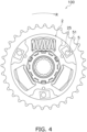
FIG. 4 , eachstopper member 5 may have a rectangular shape in an axial view. In this case, the distance between eachstopper surface 25 and eachstopper member 5 can be changed by replacing thestopper members 5 by any of a variety of types of stopper members that are different in circumferential dimension from each other and are prepared as options for thestopper members 5. - 2: First rotor, 22: Hub portion, 23: Outer flanged portion, 24: Inner flanged portion, 25: Stopper surface, 3: Second rotor, 4: Elastic member, 5: Stopper member, 51: Through hole, 6: Sprocket part, 7: Crank arm, 71: Arm body, 72: Attachment portion, 721: Distal end, 8a: Bolt, 100: Power transmission device
Claims (8)
- A bicycle power transmission device comprising:a first rotor disposed to be rotatable;a pair of second rotors disposed to interpose the first rotor therebetween in an axial direction, the pair of second rotors attached to each other so as to be detachable from each other;an elastic member elastically coupling the first rotor and the pair of second rotors; anda stopper member attached to the pair of second rotors so as to be disposed therebetween, whereinthe first rotor includes a stopper surface opposed to the stopper member at an interval in a rotational direction.
- The bicycle power transmission device according to claim 1, further comprising:a plurality of bolts configured to attach the pair of second rotors to each other so as to make the pair of second rotors detachable from each other, whereinthe stopper member includes a through hole penetrating therethrough in the axial direction, andeach of the plurality of bolts extends to penetrate the through hole.
- The bicycle power transmission device according to claim 1, further comprising:a sprocket part provided on one of the pair of second rotors; anda crank arm configured to be unitarily rotated with the first rotor.
- The bicycle power transmission device according to claim 3, whereinthe first rotor includes a hub portion, an outer flanged portion, and an inner flanged portion, the hub portion extending in the axial direction, the outer flanged portion extending radially outward from the hub portion, the inner flanged portion extending radially inward from the hub portion, andthe crank arm is attached to the inner flanged portion.
- The bicycle power transmission device according to claim 4, wherein the crank arm is spline-coupled to the inner flanged portion.
- The bicycle power transmission device according to claim 4 or 5, whereinthe crank arm includes an arm body and an attachment portion, the arm body extending in a radial direction, the attachment portion extending from an end of the arm body in the axial direction, andthe attachment portion penetrates inside the inner flanged portion, the attachment portion swaged at a distal end thereof to the inner flanged portion.
- The bicycle power transmission device according to claim 1, wherein the stopper member is attached to the pair of second rotors so as to be replaceable by another stopper member.
- The bicycle power transmission device according to claim 1, wherein the stopper member is selected from a plurality of types of stopper members different in circumferential dimension from each other.
Applications Claiming Priority (1)
| Application Number | Priority Date | Filing Date | Title |
|---|---|---|---|
| JP2022198151A JP2024084007A (en) | 2022-12-12 | 2022-12-12 | Bicycle power transmission device |
Publications (1)
| Publication Number | Publication Date |
|---|---|
| EP4385874A1 true EP4385874A1 (en) | 2024-06-19 |
Family
ID=88833726
Family Applications (1)
| Application Number | Title | Priority Date | Filing Date |
|---|---|---|---|
| EP23209381.5A Pending EP4385874A1 (en) | 2022-12-12 | 2023-11-13 | Bicycle power transmission device |
Country Status (3)
| Country | Link |
|---|---|
| EP (1) | EP4385874A1 (en) |
| JP (1) | JP2024084007A (en) |
| CN (1) | CN118182694A (en) |
Citations (4)
| Publication number | Priority date | Publication date | Assignee | Title |
|---|---|---|---|---|
| EP0965828B1 (en) * | 1998-06-18 | 2001-12-19 | Honda Giken Kogyo Kabushiki Kaisha | Input torque detecting apparatus for power assist vehicle |
| US20180037296A1 (en) * | 2015-02-14 | 2018-02-08 | Godo Kaisha IP Bridge | Rotation transmission mechanism and bicycle provided with same |
| US20180079467A1 (en) * | 2016-09-20 | 2018-03-22 | Shimano Inc. | Bicycle front sprocket assembly |
| JP2020059347A (en) | 2018-10-09 | 2020-04-16 | 株式会社エクセディ | Bicycle and power transmission device for bicycle |
-
2022
- 2022-12-12 JP JP2022198151A patent/JP2024084007A/en active Pending
-
2023
- 2023-11-13 EP EP23209381.5A patent/EP4385874A1/en active Pending
- 2023-12-11 CN CN202311694231.2A patent/CN118182694A/en active Pending
Patent Citations (4)
| Publication number | Priority date | Publication date | Assignee | Title |
|---|---|---|---|---|
| EP0965828B1 (en) * | 1998-06-18 | 2001-12-19 | Honda Giken Kogyo Kabushiki Kaisha | Input torque detecting apparatus for power assist vehicle |
| US20180037296A1 (en) * | 2015-02-14 | 2018-02-08 | Godo Kaisha IP Bridge | Rotation transmission mechanism and bicycle provided with same |
| US20180079467A1 (en) * | 2016-09-20 | 2018-03-22 | Shimano Inc. | Bicycle front sprocket assembly |
| JP2020059347A (en) | 2018-10-09 | 2020-04-16 | 株式会社エクセディ | Bicycle and power transmission device for bicycle |
Also Published As
| Publication number | Publication date |
|---|---|
| JP2024084007A (en) | 2024-06-24 |
| CN118182694A (en) | 2024-06-14 |
Similar Documents
| Publication | Publication Date | Title |
|---|---|---|
| DE112006001432B4 (en) | Drive device for a hybrid vehicle | |
| JPH0345262B2 (en) | ||
| US20240025512A1 (en) | Driving device for an electric bicycle and electric bicycle | |
| US20130165294A1 (en) | Hybrid module and torque transfer device | |
| US20210310523A1 (en) | Clutch device | |
| US10364875B2 (en) | Micro-traction drive unit and hydrostatic transmission | |
| US20210252962A1 (en) | Vehicle driving apparatus | |
| EP2050985B1 (en) | Differential gear | |
| EP4385874A1 (en) | Bicycle power transmission device | |
| EP4385875A1 (en) | Bicycle power transmission device | |
| US12158195B2 (en) | Reduction gear | |
| US10837499B2 (en) | Clutch device | |
| RU2561401C2 (en) | Dead cardan joint for helicopter drive | |
| CN103448473A (en) | Wheel rim for shaft of operation vehicle and shaft of the operation vehicle | |
| US20230003260A1 (en) | Power transmission device | |
| EP2999896B1 (en) | Flexible shaft coupling | |
| CN121990095A (en) | Bicycle power transmission device | |
| DE19943049B4 (en) | drive system | |
| US11320000B2 (en) | Clutch device | |
| RU2402701C1 (en) | Removable hub for assembly of rotating element on driven shaft | |
| US9719566B2 (en) | One-way clutch | |
| KR101806281B1 (en) | Flex Spline and Harmonic Drive Comprising It | |
| CN103917806A (en) | Vehicular fluid power transmitting device | |
| CN121990096A (en) | Bicycle power transmission device | |
| CN116495092B (en) | Front sprocket cover assembly and front sprocket assembly for manually driven vehicles |
Legal Events
| Date | Code | Title | Description |
|---|---|---|---|
| PUAI | Public reference made under article 153(3) epc to a published international application that has entered the european phase |
Free format text: ORIGINAL CODE: 0009012 |
|
| STAA | Information on the status of an ep patent application or granted ep patent |
Free format text: STATUS: THE APPLICATION HAS BEEN PUBLISHED |
|
| AK | Designated contracting states |
Kind code of ref document: A1 Designated state(s): AL AT BE BG CH CY CZ DE DK EE ES FI FR GB GR HR HU IE IS IT LI LT LU LV MC ME MK MT NL NO PL PT RO RS SE SI SK SM TR |
|
| STAA | Information on the status of an ep patent application or granted ep patent |
Free format text: STATUS: REQUEST FOR EXAMINATION WAS MADE |
|
| 17P | Request for examination filed |
Effective date: 20241030 |
|
| RBV | Designated contracting states (corrected) |
Designated state(s): AL AT BE BG CH CY CZ DE DK EE ES FI FR GB GR HR HU IE IS IT LI LT LU LV MC ME MK MT NL NO PL PT RO RS SE SI SK SM TR |