EP4385872A1 - Control system for straddled electric vehicle and straddled electric vehicle - Google Patents
Control system for straddled electric vehicle and straddled electric vehicle Download PDFInfo
- Publication number
- EP4385872A1 EP4385872A1 EP23188923.9A EP23188923A EP4385872A1 EP 4385872 A1 EP4385872 A1 EP 4385872A1 EP 23188923 A EP23188923 A EP 23188923A EP 4385872 A1 EP4385872 A1 EP 4385872A1
- Authority
- EP
- European Patent Office
- Prior art keywords
- operating member
- operating
- range
- electric motor
- drive force
- Prior art date
- Legal status (The legal status is an assumption and is not a legal conclusion. Google has not performed a legal analysis and makes no representation as to the accuracy of the status listed.)
- Granted
Links
Images





Classifications
-
- B—PERFORMING OPERATIONS; TRANSPORTING
- B62—LAND VEHICLES FOR TRAVELLING OTHERWISE THAN ON RAILS
- B62K—CYCLES; CYCLE FRAMES; CYCLE STEERING DEVICES; RIDER-OPERATED TERMINAL CONTROLS SPECIALLY ADAPTED FOR CYCLES; CYCLE AXLE SUSPENSIONS; CYCLE SIDECARS, FORECARS, OR THE LIKE
- B62K23/00—Rider-operated controls specially adapted for cycles, i.e. means for initiating control operations, e.g. levers, grips
- B62K23/02—Rider-operated controls specially adapted for cycles, i.e. means for initiating control operations, e.g. levers, grips hand actuated
- B62K23/06—Levers
-
- B—PERFORMING OPERATIONS; TRANSPORTING
- B60—VEHICLES IN GENERAL
- B60L—PROPULSION OF ELECTRICALLY-PROPELLED VEHICLES; SUPPLYING ELECTRIC POWER FOR AUXILIARY EQUIPMENT OF ELECTRICALLY-PROPELLED VEHICLES; ELECTRODYNAMIC BRAKE SYSTEMS FOR VEHICLES IN GENERAL; MAGNETIC SUSPENSION OR LEVITATION FOR VEHICLES; MONITORING OPERATING VARIABLES OF ELECTRICALLY-PROPELLED VEHICLES; ELECTRIC SAFETY DEVICES FOR ELECTRICALLY-PROPELLED VEHICLES
- B60L15/00—Methods, circuits, or devices for controlling the traction-motor speed of electrically-propelled vehicles
- B60L15/20—Methods, circuits, or devices for controlling the traction-motor speed of electrically-propelled vehicles for control of the vehicle or its driving motor to achieve a desired performance, e.g. speed, torque, programmed variation of speed
- B60L15/2054—Methods, circuits, or devices for controlling the traction-motor speed of electrically-propelled vehicles for control of the vehicle or its driving motor to achieve a desired performance, e.g. speed, torque, programmed variation of speed by controlling transmissions or clutches
-
- B—PERFORMING OPERATIONS; TRANSPORTING
- B60—VEHICLES IN GENERAL
- B60L—PROPULSION OF ELECTRICALLY-PROPELLED VEHICLES; SUPPLYING ELECTRIC POWER FOR AUXILIARY EQUIPMENT OF ELECTRICALLY-PROPELLED VEHICLES; ELECTRODYNAMIC BRAKE SYSTEMS FOR VEHICLES IN GENERAL; MAGNETIC SUSPENSION OR LEVITATION FOR VEHICLES; MONITORING OPERATING VARIABLES OF ELECTRICALLY-PROPELLED VEHICLES; ELECTRIC SAFETY DEVICES FOR ELECTRICALLY-PROPELLED VEHICLES
- B60L15/00—Methods, circuits, or devices for controlling the traction-motor speed of electrically-propelled vehicles
- B60L15/20—Methods, circuits, or devices for controlling the traction-motor speed of electrically-propelled vehicles for control of the vehicle or its driving motor to achieve a desired performance, e.g. speed, torque, programmed variation of speed
- B60L15/2009—Methods, circuits, or devices for controlling the traction-motor speed of electrically-propelled vehicles for control of the vehicle or its driving motor to achieve a desired performance, e.g. speed, torque, programmed variation of speed for braking
-
- B—PERFORMING OPERATIONS; TRANSPORTING
- B60—VEHICLES IN GENERAL
- B60L—PROPULSION OF ELECTRICALLY-PROPELLED VEHICLES; SUPPLYING ELECTRIC POWER FOR AUXILIARY EQUIPMENT OF ELECTRICALLY-PROPELLED VEHICLES; ELECTRODYNAMIC BRAKE SYSTEMS FOR VEHICLES IN GENERAL; MAGNETIC SUSPENSION OR LEVITATION FOR VEHICLES; MONITORING OPERATING VARIABLES OF ELECTRICALLY-PROPELLED VEHICLES; ELECTRIC SAFETY DEVICES FOR ELECTRICALLY-PROPELLED VEHICLES
- B60L2200/00—Type of vehicles
- B60L2200/12—Bikes
-
- B—PERFORMING OPERATIONS; TRANSPORTING
- B60—VEHICLES IN GENERAL
- B60L—PROPULSION OF ELECTRICALLY-PROPELLED VEHICLES; SUPPLYING ELECTRIC POWER FOR AUXILIARY EQUIPMENT OF ELECTRICALLY-PROPELLED VEHICLES; ELECTRODYNAMIC BRAKE SYSTEMS FOR VEHICLES IN GENERAL; MAGNETIC SUSPENSION OR LEVITATION FOR VEHICLES; MONITORING OPERATING VARIABLES OF ELECTRICALLY-PROPELLED VEHICLES; ELECTRIC SAFETY DEVICES FOR ELECTRICALLY-PROPELLED VEHICLES
- B60L2240/00—Control parameters of input or output; Target parameters
- B60L2240/40—Drive Train control parameters
- B60L2240/42—Drive Train control parameters related to electric machines
- B60L2240/423—Torque
-
- B—PERFORMING OPERATIONS; TRANSPORTING
- B60—VEHICLES IN GENERAL
- B60L—PROPULSION OF ELECTRICALLY-PROPELLED VEHICLES; SUPPLYING ELECTRIC POWER FOR AUXILIARY EQUIPMENT OF ELECTRICALLY-PROPELLED VEHICLES; ELECTRODYNAMIC BRAKE SYSTEMS FOR VEHICLES IN GENERAL; MAGNETIC SUSPENSION OR LEVITATION FOR VEHICLES; MONITORING OPERATING VARIABLES OF ELECTRICALLY-PROPELLED VEHICLES; ELECTRIC SAFETY DEVICES FOR ELECTRICALLY-PROPELLED VEHICLES
- B60L2250/00—Driver interactions
- B60L2250/24—Driver interactions by lever actuation
-
- B—PERFORMING OPERATIONS; TRANSPORTING
- B62—LAND VEHICLES FOR TRAVELLING OTHERWISE THAN ON RAILS
- B62K—CYCLES; CYCLE FRAMES; CYCLE STEERING DEVICES; RIDER-OPERATED TERMINAL CONTROLS SPECIALLY ADAPTED FOR CYCLES; CYCLE AXLE SUSPENSIONS; CYCLE SIDECARS, FORECARS, OR THE LIKE
- B62K11/00—Motorcycles, engine-assisted cycles or motor scooters with one or two wheels
- B62K11/14—Handlebar constructions, or arrangements of controls thereon, specially adapted thereto
-
- B—PERFORMING OPERATIONS; TRANSPORTING
- B62—LAND VEHICLES FOR TRAVELLING OTHERWISE THAN ON RAILS
- B62K—CYCLES; CYCLE FRAMES; CYCLE STEERING DEVICES; RIDER-OPERATED TERMINAL CONTROLS SPECIALLY ADAPTED FOR CYCLES; CYCLE AXLE SUSPENSIONS; CYCLE SIDECARS, FORECARS, OR THE LIKE
- B62K2204/00—Adaptations for driving cycles by electric motor
-
- B—PERFORMING OPERATIONS; TRANSPORTING
- B62—LAND VEHICLES FOR TRAVELLING OTHERWISE THAN ON RAILS
- B62K—CYCLES; CYCLE FRAMES; CYCLE STEERING DEVICES; RIDER-OPERATED TERMINAL CONTROLS SPECIALLY ADAPTED FOR CYCLES; CYCLE AXLE SUSPENSIONS; CYCLE SIDECARS, FORECARS, OR THE LIKE
- B62K23/00—Rider-operated controls specially adapted for cycles, i.e. means for initiating control operations, e.g. levers, grips
- B62K23/02—Rider-operated controls specially adapted for cycles, i.e. means for initiating control operations, e.g. levers, grips hand actuated
- B62K23/04—Twist grips
Definitions
- the present invention relates to a control system for a straddled electric vehicle and also relates to a straddled electric vehicle.
- a control system for a straddled electric vehicle is a control system for a straddled electric vehicle including an electric motor for driving a vehicle.
- the control system for a straddled electric vehicle includes a first operating member, a second operating member, a control device, and a load adjusting device.
- the first operating member is an operating member for controlling a drive force of the electric motor.
- the second operating member is an operating member for reducing either the drive force or a regenerative brake force of the electric motor.
- the control device controls the drive force of the electric motor in accordance with operating the first operating member and reduces either the drive force or the regenerative brake force of the electric motor in accordance with operating the second operating member.
- the load adjusting device makes an operating load acting on the second operating member vary in accordance with an amount of increasing either the drive force or the regenerative brake force of the electric motor based on an operating amount of the second operating member.
- the load adjusting device makes the operating load acting on the second operating member vary in accordance with the amount of reducing either the drive force or the regenerative brake force of the electric motor based on the operating amount of the second operating member.
- the operating load acting on the second operating member corresponding to the operating amount of the second operating member, varies with the reduction amount of either the drive force or the regenerative brake force of the electric motor; hence, an operator is more likely to feel a sense of operating the second operating member than, for instance, a configuration that the operating load is constant.
- the second operating member can be enhanced in operability.
- the second operating member may be operable in an operating range defined between a first position, corresponding to an initial position, and a second position located farthest from the first position.
- the operating range may include a progressive reduction range defined between the first position and the second position.
- the control device may gradually reduce either the drive force or the regenerative brake force of the electric motor with proximity of the second operating member to the second position in the progressive reduction range.
- the load adjusting device may gradually increase the operating load acting on the second operating member with proximity of the second operating member to the second position in the progressive reduction range. In this case, the reduction amount of either the drive force or the regenerative brake force of the electric motor increases with increase in operating load; hence, the second operating member is further enhanced in operability.
- the operating range may include a blockage range defined between the progressive reduction range and the second position.
- the control device may block either the drive force or the regenerative brake force of the electric motor when the operating amount of the second operating member falls in the blockage range.
- the load adjusting device may adjust the operating load acting on the second operating member in the blockage range to be lesser than a maximum load acting on the second operating member in the progressive reduction range. In this case, the operator can feel a sense that the operating range of the second operating member has transitioned from the progressive reduction range to the blockage range; hence, the second operating member is further enhanced in operability.
- the load adjusting device may gradually reduce the operating load acting on the second operating member with proximity of the second operating member to the second position in the blockage range. In this case, it is made easier for the operator to feel the sense that the operating range of the second operating member has transitioned from the progressive reduction range to the blockage range.
- the operating range may further include a free play range defined between the first position and the progressive reduction range.
- the control device may not reduce either the drive force or the regenerative brake force of the electric motor when the operating amount of the second operating member falls in the free play range.
- the free play range can inhibit occurrence of erroneously operating the second operating member.
- the load adjusting device may make the operating load acting on the second operating member vary such that an increase rate of the operating load acting on the second operating member becomes greater in the progressive reduction range than in the free play range.
- the operator can feel a sense that the second operating member has transitioned from the free play range to the blockage range; hence, the second operating member is further enhanced in operability.
- the control system for a straddled electric vehicle may further include a steering device.
- the steering device may include a first handle grip, a second handle grip, and a brake lever.
- the first operating member may be disposed on the first handle grip.
- the second handle grip may be disposed on an opposite side of the first handle grip with reference to a center in a vehicle width direction.
- the brake lever may be is disposed directly in front of the second handle grip.
- the second operating member may be disposed on the brake lever.
- the operator can be inhibited from releasing the thumb of a hand operating the second operating member from leaving the second handle grip.
- the operator while holding the second handle grip, the operator is enabled to put a first finger and a second finger different from the first finger on the brake lever and the second operating member, respectively.
- the operator is enabled to operate the second operating member together with the brake lever.
- the second operating member may be an operating member made in shape of a lever. In this case, the second operating member can be enhanced in operability.
- the control device may control the drive force of the electric motor to become greater in magnitude than a drive force set in accordance with an operating amount of the first operating member when the second operating member is operated from either the blockage range or the progressive reduction range to the first position at an operating speed of greater than or equal to a predetermined threshold while the first operating member is operated.
- a large drive force can be obtained momentarily; hence, a variety of traveling aspects can be realized for the straddled electric vehicle.
- a straddled electric vehicle includes an electric motor for driving a vehicle and the control system described above. Accordingly, it is made possible to provide the straddled electric vehicle including the control system described above.
- an operating member for controlling a drive force of an electric motor can be enhanced in operability in a control system for a straddled electric vehicle.
- FIG. 1 is a side view of a straddled electric vehicle 1 including a control system 10 according to the preferred embodiment.
- the straddled electric vehicle 1 is a two-wheeled electric vehicle.
- the straddled electric vehicle 1 may be another type of electric vehicle, for instance, a four-wheeled electric vehicle, a three-wheeled electric vehicle, electric snowmobile, or so forth.
- the straddled electric vehicle 1 includes a vehicle body frame 2, a steering device 3, a seat 4, a front wheel 5, a rear wheel 6, an electric motor 7, and a battery 8.
- the vehicle body frame 2 includes a head pipe 11 and a main frame 12.
- the head pipe 11 is disposed in the middle of the vehicle in a vehicle width direction.
- the main frame 12 is connected to the head pipe 11.
- the main frame 12 extends rearward from the head pipe 11.
- the steering device 3 is supported by the head pipe 11 so as to be turnable.
- the steering device 3 supports the front wheel 5 such that the front wheel 5 is made rotatable.
- the steering device 3 includes a steering shaft 13, a front fork 14, a handlebar 15, a first handle grip 16, a second handle grip 17, a first brake lever 18, and a second brake lever 19.
- the steering shaft 13 is inserted into the head pipe 11.
- the front fork 14 is connected to the steering shaft 13 and supports the front wheel 5 such that the front wheel 5 is made rotatable.
- the handlebar 15 extends in the vehicle width direction.
- the handlebar 15 is fixed to the steering shaft 13.
- the first handle grip 16 is disposed on the right of the center in the vehicle width direction.
- the second handle grip 17 is disposed on the opposite side of the first handle grip 16 with reference to the center in the vehicle width direction. In other words, the second handle grip 17 is disposed on the left of the center in the vehicle width direction.
- the first brake lever 18 is disposed directly in front of the first handle grip 16.
- the first brake lever 18 is an operating member for controlling braking of the front wheel 5.
- the second brake lever 19 is disposed directly in front of the second handle grip 17.
- the second brake lever 19 is an operating member for controlling braking of the rear wheel 6.
- the seat 4 is disposed directly behind the head pipe 11.
- the front wheel 5 is supported by the front fork 14 so as to be rotatable.
- the rear wheel 6 is supported by the main frame 12 through a swing arm so as to be rotatable.
- the rear wheel 6 is rotated by a drive force generated by the electric motor 7.
- the electric motor 7 is attached to the vehicle body frame 2.
- the electric motor 7 is connected to the rear wheel 6 through, for instance, a power transmission path composed of a reducer, a chain, and so forth.
- the electric motor 7 is driven by electric power supplied thereto from the battery 8.
- the electric motor 7 is, for instance, a three-phase alternating current motor.
- the electric motor 7 functions as a power generator caused to generate electric power by a rotational force of the rear wheel 6 in deceleration of the vehicle.
- the battery 8 is disposed directly above the electric motor 7.
- the battery 8 supplies the electric power to the electric motor 7.
- FIG. 3 is a block diagram of the control system 10.
- the control system 10 includes a first operating member 21, a second operating member 22, a throttle position sensor 23, a lever position sensor 24, a vehicle speed sensor 25, a control device 26, a motor driving device 27, and a load adjusting device 28.
- the first operating member 21 is disposed on the first handle grip 16.
- the first operating member 21 is an operating member for controlling the drive force of the electric motor 7 (a torque outputted from the electric motor 7).
- the first operating member 21 is a throttle grip twistable with respect to the handlebar 15.
- the first operating member 21 is unitarily twistable with the first handle grip 16.
- the second operating member 22 is an operating member for reducing either the drive force or a regenerative brake force of the electric motor 7.
- the second operating member 22 is an operating member made in shape of a lever.
- the second operating member 22 is disposed on the second brake lever 19.
- the second operating member 22 is disposed directly above the second brake lever 19.
- the second operating member 22 is supported to be pivotable by a pivot shaft 29 extending approximately in a vehicle up-and-down direction.
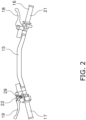
- the second operating member 22 is operable in an operating range defined between a first position (depicted with solid line in FIG. 2 ) and a second position (depicted with broken line in FIG. 2 ).
- the first position corresponds to the initial position of the second operating member 22, whereas the second position corresponds to a position remote farthest from the first position.
- the second operating member 22 is operable to pivot between the first and second positions.
- the second operating member 22 is urged to the first position by, for instance, a torsion spring 30 (see FIG. 7 ).
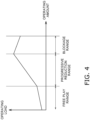
- FIG. 4 is a chart exemplifying a relation between the operating amount of the second operating member 22 and the operating load acting on the second operating member 22.
- the operating range of the second operating member 22 is divided into three sub-ranges.
- the operating range of the second operating member 22 is composed of a free play range, a progressive reduction range, and a blockage range.
- the free play range is a range defined between the first position and a progressive reduction position.
- the progressive reduction range is a range defined between the free play range and the blockage range.
- the blockage range is a range defined between the progressive reduction range and the second position.
- the operating amount of the second operating member 22 gradually increases with proximity of the second operating member 22 to the second position.
- the operating amount of the second operating member 22 corresponding to the progressive reduction range is greater than that corresponding to the free play range.
- the operating amount of the second operating member 22 corresponding to the blockage range is greater than that corresponding to the progressive reduction range.
- the throttle position sensor 23 detects the operating amount (twisted position) of the first operating member 21 and outputs a signal to the control device 26 in accordance with the operating amount of the first operating member 21.
- the throttle position sensor 23 is, for instance, a potentiometer.
- the lever position sensor 24 detects the operating amount (position) of the second operating member 22 and outputs a signal to the control device 26 in accordance with the operating amount of the second operating member 22.
- the lever position sensor 24 is, for instance, a potentiometer.
- the vehicle speed sensor 25 detects the speed of the vehicle and outputs a signal to the control device 26 in accordance with the vehicle speed.
- the control device 26 controls the drive force of the electric motor 7 in accordance with operating the first operating member 21.
- the control device 26 performs regenerative control for the electric motor 7 in deceleration of the vehicle.
- the control device 26 reduces either the drive force or the regenerative brake force of the electric motor 7 in accordance with operating the second operating member 22.
- the control device 26 controls the drive force of the electric motor 7 in accordance with the signal outputted from the throttle position sensor 23.
- the control device 26 reduces either the drive force or the regenerative brake force of the electric motor 7 in accordance with the signal outputted from the lever position sensor 24.
- the control device 26 reduces the drive force of the electric motor 7 in accordance with the operating amount of the second operating member 22.
- the control device 26 reduces the regenerative brake force of the electric motor 7 in accordance with the operating amount of the second operating member 22.
- FIG. 5 is a chart exemplifying a relation between the operating amount of the second operating member 22 and either the drive force or the regenerative brake force of the electric motor 7.
- the control device 26 when the operating amount of the second operating member 22 falls in the free play range, the control device 26 does not reduce either the drive force or the regenerative brake force of the electric motor 7.
- the control device 26 reduces either the drive force or the regenerative brake force of the electric motor 7.
- the control device 26 gradually reduces either the drive force or the regenerative brake force of the electric motor 7 with proximity of the second operating member 22 to the second position in the progressive reduction range.
- control device 26 gradually reduces either the drive force or the regenerative brake force of the electric motor 7 with increase in the operating amount of the second operating member 22 in the progressive reduction range.
- the control device 26 blocks either the drive force or the regenerative brake force of the electric motor 7.
- FIG. 6 is a chart exemplifying a relation between the operating speed of the second operating member 22 and the drive force of the electric motor 7.
- the control device 26 controls the drive force of the electric motor 7 to become greater in magnitude than the target drive force for a predetermined period of time.
- the control device 26 controls the drive force of the electric motor 7 to become greater in magnitude than the target drive force for a predetermined period of time.
- the condition that the second operating member 22 is momentarily returned to the first position refers to, for instance, a condition that the second operating member 22 is returned to the first position by an urging force exerted thereon by the torsion spring 30 when an operator releases a finger of the left hand (see FIG. 10 ) from the second operating member 22 that has been operated to either the blockage range or the progressive reduction range by the finger.
- the motor driving device 27 uses the electric power stored in the battery 8 so as to supply the electric motor 7 with electric power, the magnitude of which depends on a command value inputted thereto from the control device 26.
- the motor driving device 27 includes an inverter (not shown in the drawings).
- the motor driving device 27 converts direct current supplied thereto from the battery 8 into alternating current and supplies the alternating current to the electric motor 7.
- the motor driving device 27 causes the electric motor 7 to generate electric power in deceleration of the vehicle so as to supply the battery 8 and one or more other electric components with electric power, the magnitude of which depends on the command value inputted thereto from the control device 26.
- the motor driving device 27 includes a converter. In deceleration of the vehicle, the motor driving device 27 converts direct current obtained from the electric motor 7 into alternating current and supplies the alternating current to the battery 8 and the one or more other electric components.
- the load adjusting device 28 makes the operating load acting on the second operating member 22 vary in accordance with an amount of reducing either the drive force or the regenerative brake force of the electric motor 7 based on the operating amount of the second operating member 22. It should be noted that in the following explanation, the operating load acting on the second operating member 22 will be simply referred to as the operating load. In the present preferred embodiment, the operating load corresponds to the sum of the urging force exerted by the torsion spring 30 and a moment of force exerted by the load adjusting device 28 on the second operating member 22.
- the load adjusting device 28 gradually increases the operating load with proximity of the second operating member 22 to the second position in the free play range. In other words, the load adjusting device 28 gradually increases the operating load with increase in the operating amount of the second operating member 22 in the free play range.
- the load adjusting device 28 gradually increases the operating load with proximity of the second operating member 22 to the second position in the progressive reduction range. In other words, the load adjusting device 28 gradually increases the operating load with increase in the operating amount of the second operating member 22 in the progressive reduction range. As shown in FIG. 4 , the load adjusting device 28 makes the operating load vary such that an increase rate of the operating load becomes greater in the progressive reduction range than in the free play range. When described in detail, the load adjusting device 28 makes the operating load vary such that a ratio of the increment in the operating load to that in the operating amount of the second operating member 22 becomes greater in the progressive reduction range than in the free play range.
- the load adjusting device 28 adjusts the operating load in the blockage range to be lesser than the maximum operating load in the progressive reduction range. In other words, the load adjusting device 28 reduces the operating load when the operating amount of the second operating member 22 exceeds the progressive reduction range. In the present preferred embodiment, the load adjusting device 28 gradually reduces the operating load acting on the second operating member 22 with proximity of the second operating member 22 to the second position in the blockage range.
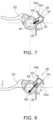
- FIGS. 7 to 9 are schematic diagrams for explaining the load adjusting device 28.
- FIG. 7 shows a condition that the second operating member 22 is located in the free play range
- FIG. 8 shows a condition that the second operating member 22 is located in the progressive reduction range
- FIG. 9 shows a condition that the second operating member 22 is located in a blockage position.
- the load adjusting device 28 includes an accommodation portion 31, a ball 32, a coil spring 33, and a cam 34.
- the accommodation portion 31, the ball 32, and the coil spring 33 are unitarily moved with the second operating member 22.
- the accommodation portion 31 is fixed to the second operating member 22.
- the ball 32 is accommodated in part in the accommodation portion 31.
- the ball 32 contacts with the cam 34.
- the coil spring 33 is accommodated in the accommodation portion 31. The coil spring 33 urges the ball 32 against the cam 34.
- the cam 34 is configured such that a force, exerted by the cam 34 on the ball 32 to press the ball 32, varies in magnitude in accordance with pivoting of the second operating member 22.
- the force, exerted by the cam 34 on the ball 32 to press the ball 32 acts in a direction that the operating load acting on the second operating member 22 increases.
- the force, exerted by the cam 34 on the ball 32 to press the ball 32 acts as the moment of force by which the second operating member 22 is pivoted clockwise in FIGS. 7 to 9 .
- the cam 34 includes a first cam surface 34a and a second cam surface 34b.
- the first cam surface 34a is configured to gradually increase the operating load with proximity of the second operating member 22 from the first position to the blockage range.
- the second cam surface 34b is disposed in adjacent to the first cam surface 34a.
- the ball 32 contacts with the first cam surface 34a when the second operating member 22 is located in the free play range and the progressive reduction range.
- the ball 32 contacts with the second cam surface 34b when the second operating member 22 is located in the blockage range.
- a moment of force M2 is greater in magnitude than a moment of force M1.
- the moment of force M2 is exerted by the load adjusting device 28 to pivot the second operating member 22 clockwise in the progressive reduction range, whereas the moment of force M1 is exerted by the load adjusting device 28 to pivot the second operating member 22 clockwise in the free play range.
- the moment of force M2 gradually increases with proximity of the second operating member 22 to the second position.
- a moment of force M3 is lesser in magnitude than the moment of force M2.
- the moment of force M3 is exerted by the load adjusting device 28 to pivot the second operating member 22 clockwise when the ball 32 is moved from the first cam surface 34a to the second cam surface 34b, namely, when the second operating member 22 is moved from the progressive reduction position to the blockage position.
- the magnitude of the operating load in the blockage range is set such that the second operating member 22 is enabled to momentarily return to the first position against the operating load when the operator stops operating the second operating member 22.
- the control device 26 controls the electric motor 7 to output, for a predetermined period of time, a drive force greater in magnitude than the target drive force set in correspondence to the torque command value corresponding to the operating amount of the first operating member 21 and rotational speed of the electric motor 7.
- the load adjusting device 28 makes the operating load acting on the second operating member 22 vary in accordance with the amount of reducing either the drive force or the regenerative brake force of the electric motor 7 based on the operating amount of the second operating member 22.
- the operating load acting on the second operating member 22, corresponding to the operating amount of the second operating member 22, varies with the reduction amount of either the drive force or the regenerative brake force of the electric motor 7; hence, the operator is more likely to feel a sense of operating the second operating member 22 than, for instance, a configuration that the operating load is constant.
- the second operating member 22 can be enhanced in operability.
- the load adjusting device 28 adjusts the operating load in the blockage range to be lesser in magnitude than the maximum operating load in the progressive reduction range; hence, the operator can feel a sense that the operating range of the second operating member 22 has transitioned from the progressive reduction range to the blockage range.
- the load adjusting device 28 makes the operating load vary such that the increase rate of the operating load becomes greater in the progressive reduction range than in the free play range; hence, the operator can feel a sense that the operating range of the second operating member 22 has transitioned from the free play range to the progressive reduction range.
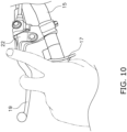
- the second operating member 22 is an operating member made in shape of a lever and is disposed on the second brake lever 19. Because of this, as shown in FIGS. 10 and 11 , while holding the second handle grip 17 with the thumb of the left hand, the operator is enabled to operate the second operating member 22 with the index finger hooked thereon and operate the second brake lever 19 with the middle finger hooked thereon. Besides, the operator is enabled to operate the second operating member 22 together with the second brake lever 19.
- the first operating member 21 may be made in form of a lever, button, accelerator pedal, or so forth.
- the second operating member 22 may be made in form of a button, twistable grip, foot lever operable by either foot of the operator, or so forth.
- the load adjusting device 28 may be changed in configuration.
- the cam 34 may be changed in positional arrangement and/or shape.
- the load adjusting device 28 may be configured to make the operating load acting on the second operating member 22 vary with an electric configuration.
Landscapes
- Engineering & Computer Science (AREA)
- Mechanical Engineering (AREA)
- Power Engineering (AREA)
- Transportation (AREA)
- Electric Propulsion And Braking For Vehicles (AREA)
- Braking Elements And Transmission Devices (AREA)
- Steering Devices For Bicycles And Motorcycles (AREA)
Abstract
Description
- The present invention relates to a control system for a straddled electric vehicle and also relates to a straddled electric vehicle.
- It has been conventionally disclosed that in a straddled electric vehicle including an electric motor as a drive source, a drive force of the electric motor is controlled through an operating member made in shape of a lever (see Publication of
Japan Patent No. 6946549 - It has been demanded to enhance the operability of the operating member for controlling the drive force of the electric motor in the straddled electric vehicle.
- It is an object of the present invention to provide a control system for a straddled electric vehicle, whereby an operating member for controlling a drive force of an electric motor can be enhanced in operability.
- A control system for a straddled electric vehicle according to an aspect of the present invention is a control system for a straddled electric vehicle including an electric motor for driving a vehicle. The control system for a straddled electric vehicle includes a first operating member, a second operating member, a control device, and a load adjusting device. The first operating member is an operating member for controlling a drive force of the electric motor. The second operating member is an operating member for reducing either the drive force or a regenerative brake force of the electric motor. The control device controls the drive force of the electric motor in accordance with operating the first operating member and reduces either the drive force or the regenerative brake force of the electric motor in accordance with operating the second operating member. The load adjusting device makes an operating load acting on the second operating member vary in accordance with an amount of increasing either the drive force or the regenerative brake force of the electric motor based on an operating amount of the second operating member.
- In the control system for a straddled electric vehicle according to the present aspect, the load adjusting device makes the operating load acting on the second operating member vary in accordance with the amount of reducing either the drive force or the regenerative brake force of the electric motor based on the operating amount of the second operating member. In other words, the operating load acting on the second operating member, corresponding to the operating amount of the second operating member, varies with the reduction amount of either the drive force or the regenerative brake force of the electric motor; hence, an operator is more likely to feel a sense of operating the second operating member than, for instance, a configuration that the operating load is constant. As a result, the second operating member can be enhanced in operability.
- The second operating member may be operable in an operating range defined between a first position, corresponding to an initial position, and a second position located farthest from the first position. The operating range may include a progressive reduction range defined between the first position and the second position. The control device may gradually reduce either the drive force or the regenerative brake force of the electric motor with proximity of the second operating member to the second position in the progressive reduction range. The load adjusting device may gradually increase the operating load acting on the second operating member with proximity of the second operating member to the second position in the progressive reduction range. In this case, the reduction amount of either the drive force or the regenerative brake force of the electric motor increases with increase in operating load; hence, the second operating member is further enhanced in operability.
- The operating range may include a blockage range defined between the progressive reduction range and the second position. The control device may block either the drive force or the regenerative brake force of the electric motor when the operating amount of the second operating member falls in the blockage range. The load adjusting device may adjust the operating load acting on the second operating member in the blockage range to be lesser than a maximum load acting on the second operating member in the progressive reduction range. In this case, the operator can feel a sense that the operating range of the second operating member has transitioned from the progressive reduction range to the blockage range; hence, the second operating member is further enhanced in operability.
- The load adjusting device may gradually reduce the operating load acting on the second operating member with proximity of the second operating member to the second position in the blockage range. In this case, it is made easier for the operator to feel the sense that the operating range of the second operating member has transitioned from the progressive reduction range to the blockage range.
- The operating range may further include a free play range defined between the first position and the progressive reduction range. The control device may not reduce either the drive force or the regenerative brake force of the electric motor when the operating amount of the second operating member falls in the free play range. In this case, the free play range can inhibit occurrence of erroneously operating the second operating member.
- The load adjusting device may make the operating load acting on the second operating member vary such that an increase rate of the operating load acting on the second operating member becomes greater in the progressive reduction range than in the free play range. In this case, the operator can feel a sense that the second operating member has transitioned from the free play range to the blockage range; hence, the second operating member is further enhanced in operability.
- The control system for a straddled electric vehicle may further include a steering device. The steering device may include a first handle grip, a second handle grip, and a brake lever. The first operating member may be disposed on the first handle grip. The second handle grip may be disposed on an opposite side of the first handle grip with reference to a center in a vehicle width direction. The brake lever may be is disposed directly in front of the second handle grip. The second operating member may be disposed on the brake lever. In this case, the operator can be inhibited from releasing the thumb of a hand operating the second operating member from leaving the second handle grip. In other words, while holding the second handle grip, the operator is enabled to put a first finger and a second finger different from the first finger on the brake lever and the second operating member, respectively. Besides, the operator is enabled to operate the second operating member together with the brake lever.
- The second operating member may be an operating member made in shape of a lever. In this case, the second operating member can be enhanced in operability.
- The control device may control the drive force of the electric motor to become greater in magnitude than a drive force set in accordance with an operating amount of the first operating member when the second operating member is operated from either the blockage range or the progressive reduction range to the first position at an operating speed of greater than or equal to a predetermined threshold while the first operating member is operated. In this case, when the second operating member is momentarily returned to the first position from the blockage range, for instance, a large drive force can be obtained momentarily; hence, a variety of traveling aspects can be realized for the straddled electric vehicle.
- A straddled electric vehicle according to another aspect of the present invention includes an electric motor for driving a vehicle and the control system described above. Accordingly, it is made possible to provide the straddled electric vehicle including the control system described above.
- Overall, according to the present invention, an operating member for controlling a drive force of an electric motor can be enhanced in operability in a control system for a straddled electric vehicle.
-
-
FIG. 1 is a side view of a straddled electric vehicle. -
FIG. 2 is a plan view of part of a steering device. -
FIG. 3 is a block diagram of a control system. -
FIG. 4 is a chart exemplifying a relation between an operating amount of a second operating member and an operating load acting on the second operating member. -
FIG. 5 is a chart exemplifying a relation between the operating amount of the second operating member and either a drive force or a regenerative brake force. -
FIG. 6 is a chart exemplifying a relation between a drive force and an operating speed of the second operating member. -
FIG. 7 is a schematic diagram for explaining a load adjusting device. -
FIG. 8 is another schematic diagram for explaining the load adjusting device. -
FIG. 9 is yet another schematic diagram for explaining the load adjusting device. -
FIG. 10 is a diagram schematically showing a state of a hand in operation of the second operating member. -
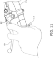
FIG. 11 is a diagram schematically showing another state of the hand in operation of the second operating member. - A control system for a straddled electric vehicle according to a preferred embodiment will be hereinafter explained with reference to drawings.
FIG. 1 is a side view of a straddledelectric vehicle 1 including acontrol system 10 according to the preferred embodiment. The straddledelectric vehicle 1 is a two-wheeled electric vehicle. The straddledelectric vehicle 1 may be another type of electric vehicle, for instance, a four-wheeled electric vehicle, a three-wheeled electric vehicle, electric snowmobile, or so forth. - The straddled
electric vehicle 1 includes a vehicle body frame 2, asteering device 3, a seat 4, a front wheel 5, a rear wheel 6, anelectric motor 7, and abattery 8. - The vehicle body frame 2 includes a
head pipe 11 and amain frame 12. Thehead pipe 11 is disposed in the middle of the vehicle in a vehicle width direction. Themain frame 12 is connected to thehead pipe 11. Themain frame 12 extends rearward from thehead pipe 11. - The
steering device 3 is supported by thehead pipe 11 so as to be turnable. Thesteering device 3 supports the front wheel 5 such that the front wheel 5 is made rotatable. As shown inFIGS. 1 and2 , thesteering device 3 includes a steeringshaft 13, afront fork 14, ahandlebar 15, afirst handle grip 16, asecond handle grip 17, afirst brake lever 18, and asecond brake lever 19. - The steering
shaft 13 is inserted into thehead pipe 11. Thefront fork 14 is connected to the steeringshaft 13 and supports the front wheel 5 such that the front wheel 5 is made rotatable. - The
handlebar 15 extends in the vehicle width direction. Thehandlebar 15 is fixed to the steeringshaft 13. Thefirst handle grip 16 is disposed on the right of the center in the vehicle width direction. Thesecond handle grip 17 is disposed on the opposite side of thefirst handle grip 16 with reference to the center in the vehicle width direction. In other words, thesecond handle grip 17 is disposed on the left of the center in the vehicle width direction. - The
first brake lever 18 is disposed directly in front of thefirst handle grip 16. Thefirst brake lever 18 is an operating member for controlling braking of the front wheel 5. Thesecond brake lever 19 is disposed directly in front of thesecond handle grip 17. Thesecond brake lever 19 is an operating member for controlling braking of the rear wheel 6. - The seat 4 is disposed directly behind the
head pipe 11. The front wheel 5 is supported by thefront fork 14 so as to be rotatable. The rear wheel 6 is supported by themain frame 12 through a swing arm so as to be rotatable. The rear wheel 6 is rotated by a drive force generated by theelectric motor 7. - The
electric motor 7 is attached to the vehicle body frame 2. Theelectric motor 7 is connected to the rear wheel 6 through, for instance, a power transmission path composed of a reducer, a chain, and so forth. Theelectric motor 7 is driven by electric power supplied thereto from thebattery 8. Theelectric motor 7 is, for instance, a three-phase alternating current motor. Theelectric motor 7 functions as a power generator caused to generate electric power by a rotational force of the rear wheel 6 in deceleration of the vehicle. - The
battery 8 is disposed directly above theelectric motor 7. Thebattery 8 supplies the electric power to theelectric motor 7. -
FIG. 3 is a block diagram of thecontrol system 10. Thecontrol system 10 includes afirst operating member 21, asecond operating member 22, athrottle position sensor 23, alever position sensor 24, avehicle speed sensor 25, acontrol device 26, amotor driving device 27, and aload adjusting device 28. - The
first operating member 21 is disposed on thefirst handle grip 16. Thefirst operating member 21 is an operating member for controlling the drive force of the electric motor 7 (a torque outputted from the electric motor 7). Thefirst operating member 21 is a throttle grip twistable with respect to thehandlebar 15. Thefirst operating member 21 is unitarily twistable with thefirst handle grip 16. - The
second operating member 22 is an operating member for reducing either the drive force or a regenerative brake force of theelectric motor 7. Thesecond operating member 22 is an operating member made in shape of a lever. Thesecond operating member 22 is disposed on thesecond brake lever 19. Thesecond operating member 22 is disposed directly above thesecond brake lever 19. Thesecond operating member 22 is supported to be pivotable by apivot shaft 29 extending approximately in a vehicle up-and-down direction. - The
second operating member 22 is operable in an operating range defined between a first position (depicted with solid line inFIG. 2 ) and a second position (depicted with broken line inFIG. 2 ). The first position corresponds to the initial position of thesecond operating member 22, whereas the second position corresponds to a position remote farthest from the first position. Thesecond operating member 22 is operable to pivot between the first and second positions. Thesecond operating member 22 is urged to the first position by, for instance, a torsion spring 30 (seeFIG. 7 ). -
FIG. 4 is a chart exemplifying a relation between the operating amount of thesecond operating member 22 and the operating load acting on thesecond operating member 22. As shown inFIG. 4 , in the present preferred embodiment, the operating range of thesecond operating member 22 is divided into three sub-ranges. When described in detail, the operating range of thesecond operating member 22 is composed of a free play range, a progressive reduction range, and a blockage range. - The free play range is a range defined between the first position and a progressive reduction position. The progressive reduction range is a range defined between the free play range and the blockage range. The blockage range is a range defined between the progressive reduction range and the second position. The operating amount of the
second operating member 22 gradually increases with proximity of thesecond operating member 22 to the second position. The operating amount of thesecond operating member 22 corresponding to the progressive reduction range is greater than that corresponding to the free play range. The operating amount of thesecond operating member 22 corresponding to the blockage range is greater than that corresponding to the progressive reduction range. - The
throttle position sensor 23 detects the operating amount (twisted position) of thefirst operating member 21 and outputs a signal to thecontrol device 26 in accordance with the operating amount of thefirst operating member 21. Thethrottle position sensor 23 is, for instance, a potentiometer. - The
lever position sensor 24 detects the operating amount (position) of thesecond operating member 22 and outputs a signal to thecontrol device 26 in accordance with the operating amount of thesecond operating member 22. Thelever position sensor 24 is, for instance, a potentiometer. - The
vehicle speed sensor 25 detects the speed of the vehicle and outputs a signal to thecontrol device 26 in accordance with the vehicle speed. - The
control device 26 controls the drive force of theelectric motor 7 in accordance with operating thefirst operating member 21. Thecontrol device 26 performs regenerative control for theelectric motor 7 in deceleration of the vehicle. Thecontrol device 26 reduces either the drive force or the regenerative brake force of theelectric motor 7 in accordance with operating thesecond operating member 22. Thecontrol device 26 controls the drive force of theelectric motor 7 in accordance with the signal outputted from thethrottle position sensor 23. Thecontrol device 26 reduces either the drive force or the regenerative brake force of theelectric motor 7 in accordance with the signal outputted from thelever position sensor 24. - When the
second operating member 22 is operated while the drive force of theelectric motor 7 is controlled in accordance with operating thefirst operating member 21, thecontrol device 26 reduces the drive force of theelectric motor 7 in accordance with the operating amount of thesecond operating member 22. - When the
second operating member 22 is operated while the vehicle decelerates by stopping operating thefirst operating member 21, thecontrol device 26 reduces the regenerative brake force of theelectric motor 7 in accordance with the operating amount of thesecond operating member 22. -
FIG. 5 is a chart exemplifying a relation between the operating amount of thesecond operating member 22 and either the drive force or the regenerative brake force of theelectric motor 7. As shown inFIG. 5 , when the operating amount of thesecond operating member 22 falls in the free play range, thecontrol device 26 does not reduce either the drive force or the regenerative brake force of theelectric motor 7. When the operating amount of thesecond operating member 22 falls in the progressive reduction range, thecontrol device 26 reduces either the drive force or the regenerative brake force of theelectric motor 7. Thecontrol device 26 gradually reduces either the drive force or the regenerative brake force of theelectric motor 7 with proximity of thesecond operating member 22 to the second position in the progressive reduction range. In other words, thecontrol device 26 gradually reduces either the drive force or the regenerative brake force of theelectric motor 7 with increase in the operating amount of thesecond operating member 22 in the progressive reduction range. When the operating amount of thesecond operating member 22 falls in the blockage range, thecontrol device 26 blocks either the drive force or the regenerative brake force of theelectric motor 7. -
FIG. 6 is a chart exemplifying a relation between the operating speed of thesecond operating member 22 and the drive force of theelectric motor 7. When thefirst operating member 21 is operated, and simultaneously, thesecond operating member 22 is operated from either the blockage range or the progressive reduction range to the first position at an operating speed of greater than or equal to a predetermined threshold, thecontrol device 26 controls the drive force of theelectric motor 7 to become greater in magnitude than a target drive force, that is, a drive force set in accordance with the operating amount of thefirst operating member 21. For example, when thefirst operating member 21 is operated during traveling, and simultaneously, the operating amount of thesecond operating member 22 falls in the blockage range, the drive force of theelectric motor 7, set in accordance with the operating amount of thefirst operating member 21, is not transmitted to the rear wheel 6. At this time, when thesecond operating member 22 is momentarily returned to the first position, thecontrol device 26 controls the drive force of theelectric motor 7 to become greater in magnitude than the target drive force for a predetermined period of time. For example, when thefirst operating member 21 is operated during traveling, and simultaneously, the operating amount of thesecond operating member 22 falls in the progressive reduction range, if thesecond operating member 22 is momentarily returned to the first position, thecontrol device 26 controls the drive force of theelectric motor 7 to become greater in magnitude than the target drive force for a predetermined period of time. The condition that thesecond operating member 22 is momentarily returned to the first position refers to, for instance, a condition that thesecond operating member 22 is returned to the first position by an urging force exerted thereon by thetorsion spring 30 when an operator releases a finger of the left hand (seeFIG. 10 ) from thesecond operating member 22 that has been operated to either the blockage range or the progressive reduction range by the finger. - The
motor driving device 27 uses the electric power stored in thebattery 8 so as to supply theelectric motor 7 with electric power, the magnitude of which depends on a command value inputted thereto from thecontrol device 26. Themotor driving device 27 includes an inverter (not shown in the drawings). Themotor driving device 27 converts direct current supplied thereto from thebattery 8 into alternating current and supplies the alternating current to theelectric motor 7. Themotor driving device 27 causes theelectric motor 7 to generate electric power in deceleration of the vehicle so as to supply thebattery 8 and one or more other electric components with electric power, the magnitude of which depends on the command value inputted thereto from thecontrol device 26. Themotor driving device 27 includes a converter. In deceleration of the vehicle, themotor driving device 27 converts direct current obtained from theelectric motor 7 into alternating current and supplies the alternating current to thebattery 8 and the one or more other electric components. - The
load adjusting device 28 makes the operating load acting on thesecond operating member 22 vary in accordance with an amount of reducing either the drive force or the regenerative brake force of theelectric motor 7 based on the operating amount of thesecond operating member 22. It should be noted that in the following explanation, the operating load acting on thesecond operating member 22 will be simply referred to as the operating load. In the present preferred embodiment, the operating load corresponds to the sum of the urging force exerted by thetorsion spring 30 and a moment of force exerted by theload adjusting device 28 on thesecond operating member 22. - As shown in
FIG. 4 , theload adjusting device 28 gradually increases the operating load with proximity of thesecond operating member 22 to the second position in the free play range. In other words, theload adjusting device 28 gradually increases the operating load with increase in the operating amount of thesecond operating member 22 in the free play range. - The
load adjusting device 28 gradually increases the operating load with proximity of thesecond operating member 22 to the second position in the progressive reduction range. In other words, theload adjusting device 28 gradually increases the operating load with increase in the operating amount of thesecond operating member 22 in the progressive reduction range. As shown inFIG. 4 , theload adjusting device 28 makes the operating load vary such that an increase rate of the operating load becomes greater in the progressive reduction range than in the free play range. When described in detail, theload adjusting device 28 makes the operating load vary such that a ratio of the increment in the operating load to that in the operating amount of thesecond operating member 22 becomes greater in the progressive reduction range than in the free play range. - The
load adjusting device 28 adjusts the operating load in the blockage range to be lesser than the maximum operating load in the progressive reduction range. In other words, theload adjusting device 28 reduces the operating load when the operating amount of thesecond operating member 22 exceeds the progressive reduction range. In the present preferred embodiment, theload adjusting device 28 gradually reduces the operating load acting on thesecond operating member 22 with proximity of thesecond operating member 22 to the second position in the blockage range. -
FIGS. 7 to 9 are schematic diagrams for explaining theload adjusting device 28.FIG. 7 shows a condition that thesecond operating member 22 is located in the free play range,FIG. 8 shows a condition that thesecond operating member 22 is located in the progressive reduction range, andFIG. 9 shows a condition that thesecond operating member 22 is located in a blockage position. - The
load adjusting device 28 includes anaccommodation portion 31, aball 32, acoil spring 33, and acam 34. Theaccommodation portion 31, theball 32, and thecoil spring 33 are unitarily moved with thesecond operating member 22. Theaccommodation portion 31 is fixed to thesecond operating member 22. Theball 32 is accommodated in part in theaccommodation portion 31. Theball 32 contacts with thecam 34. Thecoil spring 33 is accommodated in theaccommodation portion 31. Thecoil spring 33 urges theball 32 against thecam 34. - The
cam 34 is configured such that a force, exerted by thecam 34 on theball 32 to press theball 32, varies in magnitude in accordance with pivoting of thesecond operating member 22. The force, exerted by thecam 34 on theball 32 to press theball 32, acts in a direction that the operating load acting on thesecond operating member 22 increases. When described in detail, the force, exerted by thecam 34 on theball 32 to press theball 32, acts as the moment of force by which thesecond operating member 22 is pivoted clockwise inFIGS. 7 to 9 . - The
cam 34 includes afirst cam surface 34a and asecond cam surface 34b. Thefirst cam surface 34a is configured to gradually increase the operating load with proximity of thesecond operating member 22 from the first position to the blockage range. Thesecond cam surface 34b is disposed in adjacent to thefirst cam surface 34a. Theball 32 contacts with thefirst cam surface 34a when thesecond operating member 22 is located in the free play range and the progressive reduction range. Theball 32 contacts with thesecond cam surface 34b when thesecond operating member 22 is located in the blockage range. - As shown in
FIGS. 7 and 8 , a moment of force M2 is greater in magnitude than a moment of force M1. The moment of force M2 is exerted by theload adjusting device 28 to pivot thesecond operating member 22 clockwise in the progressive reduction range, whereas the moment of force M1 is exerted by theload adjusting device 28 to pivot thesecond operating member 22 clockwise in the free play range. The moment of force M2 gradually increases with proximity of thesecond operating member 22 to the second position. - As shown in
FIG. 9 , a moment of force M3 is lesser in magnitude than the moment of force M2. The moment of force M3 is exerted by theload adjusting device 28 to pivot thesecond operating member 22 clockwise when theball 32 is moved from thefirst cam surface 34a to thesecond cam surface 34b, namely, when thesecond operating member 22 is moved from the progressive reduction position to the blockage position. It should be noted that the magnitude of the operating load in the blockage range is set such that thesecond operating member 22 is enabled to momentarily return to the first position against the operating load when the operator stops operating thesecond operating member 22. Besides, when thesecond operating member 22 is momentarily returned to the first position from the blockage range as a result of releasing the left hand of the operator from thesecond operating member 22, thecontrol device 26 controls theelectric motor 7 to output, for a predetermined period of time, a drive force greater in magnitude than the target drive force set in correspondence to the torque command value corresponding to the operating amount of thefirst operating member 21 and rotational speed of theelectric motor 7. - In the
control system 10 according to the present aspect, theload adjusting device 28 makes the operating load acting on thesecond operating member 22 vary in accordance with the amount of reducing either the drive force or the regenerative brake force of theelectric motor 7 based on the operating amount of thesecond operating member 22. In other words, the operating load acting on thesecond operating member 22, corresponding to the operating amount of thesecond operating member 22, varies with the reduction amount of either the drive force or the regenerative brake force of theelectric motor 7; hence, the operator is more likely to feel a sense of operating thesecond operating member 22 than, for instance, a configuration that the operating load is constant. As a result, thesecond operating member 22 can be enhanced in operability. - The
load adjusting device 28 adjusts the operating load in the blockage range to be lesser in magnitude than the maximum operating load in the progressive reduction range; hence, the operator can feel a sense that the operating range of thesecond operating member 22 has transitioned from the progressive reduction range to the blockage range. - The
load adjusting device 28 makes the operating load vary such that the increase rate of the operating load becomes greater in the progressive reduction range than in the free play range; hence, the operator can feel a sense that the operating range of thesecond operating member 22 has transitioned from the free play range to the progressive reduction range. - The
second operating member 22 is an operating member made in shape of a lever and is disposed on thesecond brake lever 19. Because of this, as shown inFIGS. 10 and11 , while holding thesecond handle grip 17 with the thumb of the left hand, the operator is enabled to operate thesecond operating member 22 with the index finger hooked thereon and operate thesecond brake lever 19 with the middle finger hooked thereon. Besides, the operator is enabled to operate thesecond operating member 22 together with thesecond brake lever 19. - One preferred embodiment of the present invention has been explained above. However, the present invention is not limited to the preferred embodiment described above, and a variety of changes can be made without departing from the gist of the present invention.
- The
first operating member 21 may be made in form of a lever, button, accelerator pedal, or so forth. Thesecond operating member 22 may be made in form of a button, twistable grip, foot lever operable by either foot of the operator, or so forth. - The
load adjusting device 28 may be changed in configuration. Thecam 34 may be changed in positional arrangement and/or shape. Theload adjusting device 28 may be configured to make the operating load acting on thesecond operating member 22 vary with an electric configuration. -
- 1
- Straddled electric vehicle
- 3
- Steering device
- 16
- First handle grip
- 17
- Second handle grip
- 19
- Second brake lever (exemplary brake lever)
- 21
- First operating member
- 22
- Second operating member
- 26
- Control device
- 28
- Load adjusting device
Claims (11)
- A control system (10) for a straddled electric vehicle (1) including an electric motor (7) for driving a vehicle (1), the control system (10) comprising:a first operating member (21) for controlling a drive force of the electric motor (7);a second operating member (22) for reducing either the drive force or a regenerative brake force of the electric motor (7);a control device (26) controlling the drive force of the electric motor (7) in accordance with operation of the first operating member (21), the control device (26) reducing either the drive force or the regenerative brake force of the electric motor (7) in accordance with the operation of the second operating member (22); anda load adjusting device (28) making an operating load acting on the second operating member (22) vary in accordance with an amount of reducing either the drive force or the regenerative brake force of the electric motor (7) based on an operating amount of the second operating member (22).
- The control system for a straddled electric vehicle (1) according to claim 1, whereinthe second operating member (22) is operable in an operating range defined between a first position and a second position, the first position corresponding to an initial position, the second position located farthest from the first position,the operating range includes a progressive reduction range defined between the first position and the second position,the control device (26) gradually reduces either the drive force or the regenerative brake force of the electric motor (7) with proximity of the second operating member (22) to the second position in the progressive reduction range, andthe load adjusting device (28) gradually increases the operating load acting on the second operating member (22) with proximity of the second operating member (22) to the second position in the progressive reduction range.
- The control system for a straddled electric vehicle (1) according to claim 2, whereinthe operating range includes a blockage range defined between the progressive reduction range and the second position,the control device (26) blocks either the drive force or the regenerative brake force of the electric motor (7) when the operating amount of the second operating member (22) falls in the blockage range, andthe load adjusting device (28) adjusts the operating load acting on the second operating member (22) in the blockage range to be lesser than a maximum load acting on the second operating member (22) in the progressive reduction range.
- The control system for a straddled electric vehicle (1) according to claim 3, wherein the load adjusting device (28) gradually reduces the operating load acting on the second operating member (22) with proximity of the second operating member (22) to the second position in the blockage range.
- The control system for a straddled electric vehicle (1) according to any one of claims 2 to 4, whereinthe operating range further includes a free play range defined between the first position and the progressive reduction range, andthe control device (26) does not reduce either the drive force or the regenerative brake force of the electric motor (7) when the operating amount of the second operating member (22) falls in the free play range.
- The control system for a straddled electric vehicle (1) according to claim 5, wherein the load adjusting device (28) makes the operating load acting on the second operating member (22) vary such that an increase rate of the operating load acting on the second operating member (22) becomes greater in the progressive reduction range than in the free play range.
- The control system for a straddled electric vehicle according to claim 1, whereinthe second operating member (22) is operable in an operating range defined between a first position and a second position, the first position corresponding to an initial position, the second position located farthest from the first position,the operating range includes a free play range and a progressive reduction range, the free play range defined between the first position and the second position, the progressive reduction range defined between the free play range and the second position,the control device (26) does not reduce either the drive force or the regenerative brake force of the electric motor (7) when the operating amount of the second operating member falls in the free play range, the control device (26) reducing either the drive force or the regenerative brake force of the electric motor (7) when the operating amount of the second operating member (22) falls in the progressive reduction range, andthe load adjusting device (28) makes the operating load acting on the second operating member (22) vary such that an increase rate of the operating load acting on the second operating member (22) becomes greater in the progressive reduction range than in the free play range.
- The control system for a straddled electric vehicle (1) according to any one of claims 1 to 7, further comprising:a steering device (3) including a first handle grip (16), a second handle grip (17), and a brake lever (19), the first operating member (21) being disposed on the first handle grip (16), the second handle grip (17) being disposed on an opposite side of the first handle grip (16) with reference to a center in a vehicle width direction, the brake lever (18, 19) being disposed directly in front of the second handle grip (17), whereinthe second operating member (22) is disposed on the brake lever (19).
- The control system for a straddled electric vehicle (1) according to any one of claims 1 to 8, wherein the second operating member (22) is an operating member made in shape of a lever.
- The control system for a straddled electric vehicle according to claim 3, wherein the control device (26) controls the drive force of the electric motor (7) to become greater in magnitude than a drive force set in accordance with an operating amount of the first operating member (21) when the second operating member (22) is operated from either the blockage range or the progressive reduction range to the first position at an operating speed of greater than or equal to a predetermined threshold while the first operating member (21) is operated.
- A straddled electric vehicle (1) comprising:an electric motor (7) for driving a vehicle; andthe control system (26) according to any one of claims 1 to 10.
Applications Claiming Priority (1)
| Application Number | Priority Date | Filing Date | Title |
|---|---|---|---|
| JP2022200030A JP2024085502A (en) | 2022-12-15 | 2022-12-15 | Control system for straddle-type electric vehicle and straddle-type electric vehicle |
Publications (2)
| Publication Number | Publication Date |
|---|---|
| EP4385872A1 true EP4385872A1 (en) | 2024-06-19 |
| EP4385872B1 EP4385872B1 (en) | 2025-10-15 |
Family
ID=87553851
Family Applications (1)
| Application Number | Title | Priority Date | Filing Date |
|---|---|---|---|
| EP23188923.9A Active EP4385872B1 (en) | 2022-12-15 | 2023-08-01 | Control system for straddled electric vehicle and straddled electric vehicle |
Country Status (3)
| Country | Link |
|---|---|
| US (1) | US12434569B2 (en) |
| EP (1) | EP4385872B1 (en) |
| JP (1) | JP2024085502A (en) |
Citations (5)
| Publication number | Priority date | Publication date | Assignee | Title |
|---|---|---|---|---|
| JPH0646549B2 (en) | 1986-07-21 | 1994-06-15 | ニチコン株式会社 | X-ray generator |
| US8505673B2 (en) * | 2011-12-12 | 2013-08-13 | Honda Motor Co., Ltd. | Control system for a vehicle |
| EP2910401B1 (en) * | 2012-10-22 | 2020-01-08 | Kawasaki Jukogyo Kabushiki Kaisha | Regenerative brake control system of electric vehicle |
| EP3730337A1 (en) * | 2019-01-16 | 2020-10-28 | Harley-Davidson Motor Company Group, LLC | Two-wheeled vehicle with virtual braking and virtual clutch |
| EP2660093B1 (en) * | 2010-12-28 | 2021-11-17 | Kawasaki Jukogyo Kabushiki Kaisha | Regeneration control system for electric vehicle |
Family Cites Families (3)
| Publication number | Priority date | Publication date | Assignee | Title |
|---|---|---|---|---|
| CN104718100B (en) * | 2012-10-22 | 2017-03-08 | 川崎重工业株式会社 | The regenerative brake control system of electric vehicle |
| JP6946549B2 (en) | 2018-03-29 | 2021-10-06 | 本田技研工業株式会社 | Drive control device for electric vehicles |
| US11866117B2 (en) * | 2019-01-16 | 2024-01-09 | Livewire Ev, Llc | Motorcycle with virtual braking and virtual clutch |
-
2022
- 2022-12-15 JP JP2022200030A patent/JP2024085502A/en active Pending
-
2023
- 2023-08-01 EP EP23188923.9A patent/EP4385872B1/en active Active
- 2023-10-31 US US18/498,653 patent/US12434569B2/en active Active
Patent Citations (5)
| Publication number | Priority date | Publication date | Assignee | Title |
|---|---|---|---|---|
| JPH0646549B2 (en) | 1986-07-21 | 1994-06-15 | ニチコン株式会社 | X-ray generator |
| EP2660093B1 (en) * | 2010-12-28 | 2021-11-17 | Kawasaki Jukogyo Kabushiki Kaisha | Regeneration control system for electric vehicle |
| US8505673B2 (en) * | 2011-12-12 | 2013-08-13 | Honda Motor Co., Ltd. | Control system for a vehicle |
| EP2910401B1 (en) * | 2012-10-22 | 2020-01-08 | Kawasaki Jukogyo Kabushiki Kaisha | Regenerative brake control system of electric vehicle |
| EP3730337A1 (en) * | 2019-01-16 | 2020-10-28 | Harley-Davidson Motor Company Group, LLC | Two-wheeled vehicle with virtual braking and virtual clutch |
Also Published As
| Publication number | Publication date |
|---|---|
| EP4385872B1 (en) | 2025-10-15 |
| US20240198816A1 (en) | 2024-06-20 |
| JP2024085502A (en) | 2024-06-27 |
| US12434569B2 (en) | 2025-10-07 |
Similar Documents
| Publication | Publication Date | Title |
|---|---|---|
| CN104718100B (en) | The regenerative brake control system of electric vehicle | |
| JP5478739B2 (en) | Regenerative control system for electric vehicles | |
| JP6014159B2 (en) | Regenerative brake control system for electric vehicles | |
| JP7269772B2 (en) | vehicle | |
| JP2005520472A (en) | Regenerative braking system for electric vehicles | |
| KR101716724B1 (en) | Riding-type rice transplanter | |
| EP3800381B1 (en) | Quickshifter-equipped vehicle control unit and quickshifter-equipped motorcycle | |
| CN111936346B (en) | Drive control device for electric vehicle | |
| JP5478738B2 (en) | Electric vehicle acceleration control system | |
| WO2012090250A1 (en) | Electric vehicle | |
| EP4477522A1 (en) | Method and system for controlling electric bicycle | |
| JP2014176256A (en) | Regeneration control device | |
| EP4385872A1 (en) | Control system for straddled electric vehicle and straddled electric vehicle | |
| EP4385871A1 (en) | Control system for straddled electric vehicle and straddled electric vehicle | |
| EP4316965A1 (en) | Vehicle | |
| JP2021145458A (en) | Driving force control system |
Legal Events
| Date | Code | Title | Description |
|---|---|---|---|
| PUAI | Public reference made under article 153(3) epc to a published international application that has entered the european phase |
Free format text: ORIGINAL CODE: 0009012 |
|
| STAA | Information on the status of an ep patent application or granted ep patent |
Free format text: STATUS: REQUEST FOR EXAMINATION WAS MADE |
|
| 17P | Request for examination filed |
Effective date: 20230801 |
|
| AK | Designated contracting states |
Kind code of ref document: A1 Designated state(s): AL AT BE BG CH CY CZ DE DK EE ES FI FR GB GR HR HU IE IS IT LI LT LU LV MC ME MK MT NL NO PL PT RO RS SE SI SK SM TR |
|
| P01 | Opt-out of the competence of the unified patent court (upc) registered |
Free format text: CASE NUMBER: APP_39923/2024 Effective date: 20240704 |
|
| STAA | Information on the status of an ep patent application or granted ep patent |
Free format text: STATUS: EXAMINATION IS IN PROGRESS |
|
| 17Q | First examination report despatched |
Effective date: 20241015 |
|
| GRAP | Despatch of communication of intention to grant a patent |
Free format text: ORIGINAL CODE: EPIDOSNIGR1 |
|
| STAA | Information on the status of an ep patent application or granted ep patent |
Free format text: STATUS: GRANT OF PATENT IS INTENDED |
|
| RIC1 | Information provided on ipc code assigned before grant |
Ipc: B62K 23/04 20060101ALN20250404BHEP Ipc: B62K 11/14 20060101ALN20250404BHEP Ipc: B60L 15/20 20060101ALI20250404BHEP Ipc: B60L 7/26 20060101ALI20250404BHEP Ipc: B60L 1/00 20060101ALI20250404BHEP Ipc: B62K 23/06 20060101AFI20250404BHEP |
|
| INTG | Intention to grant announced |
Effective date: 20250508 |
|
| GRAS | Grant fee paid |
Free format text: ORIGINAL CODE: EPIDOSNIGR3 |
|
| GRAA | (expected) grant |
Free format text: ORIGINAL CODE: 0009210 |
|
| STAA | Information on the status of an ep patent application or granted ep patent |
Free format text: STATUS: THE PATENT HAS BEEN GRANTED |
|
| AK | Designated contracting states |
Kind code of ref document: B1 Designated state(s): AL AT BE BG CH CY CZ DE DK EE ES FI FR GB GR HR HU IE IS IT LI LT LU LV MC ME MK MT NL NO PL PT RO RS SE SI SK SM TR |
|
| REG | Reference to a national code |
Ref country code: GB Ref legal event code: FG4D Ref country code: CH Ref legal event code: F10 Free format text: ST27 STATUS EVENT CODE: U-0-0-F10-F00 (AS PROVIDED BY THE NATIONAL OFFICE) Effective date: 20251015 |
|
| REG | Reference to a national code |
Ref country code: IE Ref legal event code: FG4D |
|
| REG | Reference to a national code |
Ref country code: DE Ref legal event code: R096 Ref document number: 602023007488 Country of ref document: DE |
|
| REG | Reference to a national code |
Ref country code: NL Ref legal event code: MP Effective date: 20251015 |
|
| REG | Reference to a national code |
Ref country code: AT Ref legal event code: MK05 Ref document number: 1846747 Country of ref document: AT Kind code of ref document: T Effective date: 20251015 |
|
| PG25 | Lapsed in a contracting state [announced via postgrant information from national office to epo] |
Ref country code: NL Free format text: LAPSE BECAUSE OF FAILURE TO SUBMIT A TRANSLATION OF THE DESCRIPTION OR TO PAY THE FEE WITHIN THE PRESCRIBED TIME-LIMIT Effective date: 20251015 |
|
| PG25 | Lapsed in a contracting state [announced via postgrant information from national office to epo] |
Ref country code: ES Free format text: LAPSE BECAUSE OF FAILURE TO SUBMIT A TRANSLATION OF THE DESCRIPTION OR TO PAY THE FEE WITHIN THE PRESCRIBED TIME-LIMIT Effective date: 20251015 |
|
| REG | Reference to a national code |
Ref country code: LT Ref legal event code: MG9D |
|
| PG25 | Lapsed in a contracting state [announced via postgrant information from national office to epo] |
Ref country code: NO Free format text: LAPSE BECAUSE OF FAILURE TO SUBMIT A TRANSLATION OF THE DESCRIPTION OR TO PAY THE FEE WITHIN THE PRESCRIBED TIME-LIMIT Effective date: 20260115 |
|
| PG25 | Lapsed in a contracting state [announced via postgrant information from national office to epo] |
Ref country code: AT Free format text: LAPSE BECAUSE OF FAILURE TO SUBMIT A TRANSLATION OF THE DESCRIPTION OR TO PAY THE FEE WITHIN THE PRESCRIBED TIME-LIMIT Effective date: 20251015 Ref country code: FI Free format text: LAPSE BECAUSE OF FAILURE TO SUBMIT A TRANSLATION OF THE DESCRIPTION OR TO PAY THE FEE WITHIN THE PRESCRIBED TIME-LIMIT Effective date: 20251015 Ref country code: HR Free format text: LAPSE BECAUSE OF FAILURE TO SUBMIT A TRANSLATION OF THE DESCRIPTION OR TO PAY THE FEE WITHIN THE PRESCRIBED TIME-LIMIT Effective date: 20251015 |
|
| PG25 | Lapsed in a contracting state [announced via postgrant information from national office to epo] |
Ref country code: RS Free format text: LAPSE BECAUSE OF FAILURE TO SUBMIT A TRANSLATION OF THE DESCRIPTION OR TO PAY THE FEE WITHIN THE PRESCRIBED TIME-LIMIT Effective date: 20260115 |
|
| PG25 | Lapsed in a contracting state [announced via postgrant information from national office to epo] |
Ref country code: IS Free format text: LAPSE BECAUSE OF FAILURE TO SUBMIT A TRANSLATION OF THE DESCRIPTION OR TO PAY THE FEE WITHIN THE PRESCRIBED TIME-LIMIT Effective date: 20260215 |
|
| PG25 | Lapsed in a contracting state [announced via postgrant information from national office to epo] |
Ref country code: PT Free format text: LAPSE BECAUSE OF FAILURE TO SUBMIT A TRANSLATION OF THE DESCRIPTION OR TO PAY THE FEE WITHIN THE PRESCRIBED TIME-LIMIT Effective date: 20260216 |
|
| PG25 | Lapsed in a contracting state [announced via postgrant information from national office to epo] |
Ref country code: PL Free format text: LAPSE BECAUSE OF FAILURE TO SUBMIT A TRANSLATION OF THE DESCRIPTION OR TO PAY THE FEE WITHIN THE PRESCRIBED TIME-LIMIT Effective date: 20251015 |
|
| PG25 | Lapsed in a contracting state [announced via postgrant information from national office to epo] |
Ref country code: LV Free format text: LAPSE BECAUSE OF FAILURE TO SUBMIT A TRANSLATION OF THE DESCRIPTION OR TO PAY THE FEE WITHIN THE PRESCRIBED TIME-LIMIT Effective date: 20251015 |