EP4385821A1 - Media module, method of controlling media module, and vehicle including media module - Google Patents
Media module, method of controlling media module, and vehicle including media module Download PDFInfo
- Publication number
- EP4385821A1 EP4385821A1 EP23179920.6A EP23179920A EP4385821A1 EP 4385821 A1 EP4385821 A1 EP 4385821A1 EP 23179920 A EP23179920 A EP 23179920A EP 4385821 A1 EP4385821 A1 EP 4385821A1
- Authority
- EP
- European Patent Office
- Prior art keywords
- reflection plate
- pedestrian
- media module
- light
- module
- Prior art date
- Legal status (The legal status is an assumption and is not a legal conclusion. Google has not performed a legal analysis and makes no representation as to the accuracy of the status listed.)
- Granted
Links
Images





Classifications
-
- B—PERFORMING OPERATIONS; TRANSPORTING
- B60—VEHICLES IN GENERAL
- B60Q—ARRANGEMENT OF SIGNALLING OR LIGHTING DEVICES, THE MOUNTING OR SUPPORTING THEREOF OR CIRCUITS THEREFOR, FOR VEHICLES IN GENERAL
- B60Q1/00—Arrangement of optical signalling or lighting devices, the mounting or supporting thereof or circuits therefor
- B60Q1/26—Arrangement of optical signalling or lighting devices, the mounting or supporting thereof or circuits therefor the devices being primarily intended to indicate the vehicle, or parts thereof, or to give signals, to other traffic
- B60Q1/50—Arrangement of optical signalling or lighting devices, the mounting or supporting thereof or circuits therefor the devices being primarily intended to indicate the vehicle, or parts thereof, or to give signals, to other traffic for indicating other intentions or conditions, e.g. request for waiting or overtaking
-
- B—PERFORMING OPERATIONS; TRANSPORTING
- B60—VEHICLES IN GENERAL
- B60Q—ARRANGEMENT OF SIGNALLING OR LIGHTING DEVICES, THE MOUNTING OR SUPPORTING THEREOF OR CIRCUITS THEREFOR, FOR VEHICLES IN GENERAL
- B60Q1/00—Arrangement of optical signalling or lighting devices, the mounting or supporting thereof or circuits therefor
- B60Q1/26—Arrangement of optical signalling or lighting devices, the mounting or supporting thereof or circuits therefor the devices being primarily intended to indicate the vehicle, or parts thereof, or to give signals, to other traffic
-
- B—PERFORMING OPERATIONS; TRANSPORTING
- B60—VEHICLES IN GENERAL
- B60Q—ARRANGEMENT OF SIGNALLING OR LIGHTING DEVICES, THE MOUNTING OR SUPPORTING THEREOF OR CIRCUITS THEREFOR, FOR VEHICLES IN GENERAL
- B60Q1/00—Arrangement of optical signalling or lighting devices, the mounting or supporting thereof or circuits therefor
- B60Q1/26—Arrangement of optical signalling or lighting devices, the mounting or supporting thereof or circuits therefor the devices being primarily intended to indicate the vehicle, or parts thereof, or to give signals, to other traffic
- B60Q1/50—Arrangement of optical signalling or lighting devices, the mounting or supporting thereof or circuits therefor the devices being primarily intended to indicate the vehicle, or parts thereof, or to give signals, to other traffic for indicating other intentions or conditions, e.g. request for waiting or overtaking
- B60Q1/525—Arrangement of optical signalling or lighting devices, the mounting or supporting thereof or circuits therefor the devices being primarily intended to indicate the vehicle, or parts thereof, or to give signals, to other traffic for indicating other intentions or conditions, e.g. request for waiting or overtaking automatically indicating risk of collision between vehicles in traffic or with pedestrians, e.g. after risk assessment using the vehicle sensor data
-
- B—PERFORMING OPERATIONS; TRANSPORTING
- B60—VEHICLES IN GENERAL
- B60Q—ARRANGEMENT OF SIGNALLING OR LIGHTING DEVICES, THE MOUNTING OR SUPPORTING THEREOF OR CIRCUITS THEREFOR, FOR VEHICLES IN GENERAL
- B60Q1/00—Arrangement of optical signalling or lighting devices, the mounting or supporting thereof or circuits therefor
- B60Q1/02—Arrangement of optical signalling or lighting devices, the mounting or supporting thereof or circuits therefor the devices being primarily intended to illuminate the way ahead or to illuminate other areas of way or environments
- B60Q1/24—Arrangement of optical signalling or lighting devices, the mounting or supporting thereof or circuits therefor the devices being primarily intended to illuminate the way ahead or to illuminate other areas of way or environments for lighting other areas than only the way ahead
-
- B—PERFORMING OPERATIONS; TRANSPORTING
- B60—VEHICLES IN GENERAL
- B60Q—ARRANGEMENT OF SIGNALLING OR LIGHTING DEVICES, THE MOUNTING OR SUPPORTING THEREOF OR CIRCUITS THEREFOR, FOR VEHICLES IN GENERAL
- B60Q1/00—Arrangement of optical signalling or lighting devices, the mounting or supporting thereof or circuits therefor
- B60Q1/26—Arrangement of optical signalling or lighting devices, the mounting or supporting thereof or circuits therefor the devices being primarily intended to indicate the vehicle, or parts thereof, or to give signals, to other traffic
- B60Q1/50—Arrangement of optical signalling or lighting devices, the mounting or supporting thereof or circuits therefor the devices being primarily intended to indicate the vehicle, or parts thereof, or to give signals, to other traffic for indicating other intentions or conditions, e.g. request for waiting or overtaking
- B60Q1/52—Arrangement of optical signalling or lighting devices, the mounting or supporting thereof or circuits therefor the devices being primarily intended to indicate the vehicle, or parts thereof, or to give signals, to other traffic for indicating other intentions or conditions, e.g. request for waiting or overtaking for indicating emergencies
-
- B—PERFORMING OPERATIONS; TRANSPORTING
- B60—VEHICLES IN GENERAL
- B60Q—ARRANGEMENT OF SIGNALLING OR LIGHTING DEVICES, THE MOUNTING OR SUPPORTING THEREOF OR CIRCUITS THEREFOR, FOR VEHICLES IN GENERAL
- B60Q5/00—Arrangement or adaptation of acoustic signal devices
-
- B—PERFORMING OPERATIONS; TRANSPORTING
- B60—VEHICLES IN GENERAL
- B60Q—ARRANGEMENT OF SIGNALLING OR LIGHTING DEVICES, THE MOUNTING OR SUPPORTING THEREOF OR CIRCUITS THEREFOR, FOR VEHICLES IN GENERAL
- B60Q5/00—Arrangement or adaptation of acoustic signal devices
- B60Q5/005—Arrangement or adaptation of acoustic signal devices automatically actuated
-
- B—PERFORMING OPERATIONS; TRANSPORTING
- B60—VEHICLES IN GENERAL
- B60Q—ARRANGEMENT OF SIGNALLING OR LIGHTING DEVICES, THE MOUNTING OR SUPPORTING THEREOF OR CIRCUITS THEREFOR, FOR VEHICLES IN GENERAL
- B60Q5/00—Arrangement or adaptation of acoustic signal devices
- B60Q5/005—Arrangement or adaptation of acoustic signal devices automatically actuated
- B60Q5/006—Arrangement or adaptation of acoustic signal devices automatically actuated indicating risk of collision between vehicles or with pedestrians
-
- B—PERFORMING OPERATIONS; TRANSPORTING
- B60—VEHICLES IN GENERAL
- B60R—VEHICLES, VEHICLE FITTINGS, OR VEHICLE PARTS, NOT OTHERWISE PROVIDED FOR
- B60R11/00—Arrangements for holding or mounting articles, not otherwise provided for
- B60R11/02—Arrangements for holding or mounting articles, not otherwise provided for for radio sets, television sets, telephones, or the like; Arrangement of controls thereof
- B60R11/0217—Arrangements for holding or mounting articles, not otherwise provided for for radio sets, television sets, telephones, or the like; Arrangement of controls thereof for loud-speakers
-
- B—PERFORMING OPERATIONS; TRANSPORTING
- B60—VEHICLES IN GENERAL
- B60R—VEHICLES, VEHICLE FITTINGS, OR VEHICLE PARTS, NOT OTHERWISE PROVIDED FOR
- B60R21/00—Arrangements or fittings on vehicles for protecting or preventing injuries to occupants or pedestrians in case of accidents or other traffic risks
- B60R21/34—Protecting non-occupants of a vehicle, e.g. pedestrians
-
- F—MECHANICAL ENGINEERING; LIGHTING; HEATING; WEAPONS; BLASTING
- F21—LIGHTING
- F21S—NON-PORTABLE LIGHTING DEVICES; SYSTEMS THEREOF; VEHICLE LIGHTING DEVICES SPECIALLY ADAPTED FOR VEHICLE EXTERIORS
- F21S43/00—Signalling devices specially adapted for vehicle exteriors, e.g. brake lamps, direction indicator lights or reversing lights
- F21S43/30—Signalling devices specially adapted for vehicle exteriors, e.g. brake lamps, direction indicator lights or reversing lights characterised by reflectors
-
- F—MECHANICAL ENGINEERING; LIGHTING; HEATING; WEAPONS; BLASTING
- F21—LIGHTING
- F21S—NON-PORTABLE LIGHTING DEVICES; SYSTEMS THEREOF; VEHICLE LIGHTING DEVICES SPECIALLY ADAPTED FOR VEHICLE EXTERIORS
- F21S43/00—Signalling devices specially adapted for vehicle exteriors, e.g. brake lamps, direction indicator lights or reversing lights
- F21S43/30—Signalling devices specially adapted for vehicle exteriors, e.g. brake lamps, direction indicator lights or reversing lights characterised by reflectors
- F21S43/37—Attachment thereof
-
- F—MECHANICAL ENGINEERING; LIGHTING; HEATING; WEAPONS; BLASTING
- F21—LIGHTING
- F21S—NON-PORTABLE LIGHTING DEVICES; SYSTEMS THEREOF; VEHICLE LIGHTING DEVICES SPECIALLY ADAPTED FOR VEHICLE EXTERIORS
- F21S43/00—Signalling devices specially adapted for vehicle exteriors, e.g. brake lamps, direction indicator lights or reversing lights
- F21S43/601—Signalling devices specially adapted for vehicle exteriors, e.g. brake lamps, direction indicator lights or reversing lights characterised by variable optical properties, e.g. involving the use of LCD or movable parts
-
- B—PERFORMING OPERATIONS; TRANSPORTING
- B60—VEHICLES IN GENERAL
- B60Q—ARRANGEMENT OF SIGNALLING OR LIGHTING DEVICES, THE MOUNTING OR SUPPORTING THEREOF OR CIRCUITS THEREFOR, FOR VEHICLES IN GENERAL
- B60Q2300/00—Indexing codes for automatically adjustable headlamps or automatically dimmable headlamps
- B60Q2300/40—Indexing codes relating to other road users or special conditions
-
- B—PERFORMING OPERATIONS; TRANSPORTING
- B60—VEHICLES IN GENERAL
- B60Q—ARRANGEMENT OF SIGNALLING OR LIGHTING DEVICES, THE MOUNTING OR SUPPORTING THEREOF OR CIRCUITS THEREFOR, FOR VEHICLES IN GENERAL
- B60Q2400/00—Special features or arrangements of exterior signal lamps for vehicles
- B60Q2400/50—Projected symbol or information, e.g. onto the road or car body
-
- B—PERFORMING OPERATIONS; TRANSPORTING
- B60—VEHICLES IN GENERAL
- B60R—VEHICLES, VEHICLE FITTINGS, OR VEHICLE PARTS, NOT OTHERWISE PROVIDED FOR
- B60R11/00—Arrangements for holding or mounting articles, not otherwise provided for
- B60R2011/0042—Arrangements for holding or mounting articles, not otherwise provided for characterised by mounting means
- B60R2011/008—Adjustable or movable supports
- B60R2011/0085—Adjustable or movable supports with adjustment by rotation in their operational position
-
- B—PERFORMING OPERATIONS; TRANSPORTING
- B60—VEHICLES IN GENERAL
- B60R—VEHICLES, VEHICLE FITTINGS, OR VEHICLE PARTS, NOT OTHERWISE PROVIDED FOR
- B60R11/00—Arrangements for holding or mounting articles, not otherwise provided for
- B60R2011/0042—Arrangements for holding or mounting articles, not otherwise provided for characterised by mounting means
- B60R2011/008—Adjustable or movable supports
- B60R2011/0092—Adjustable or movable supports with motorization
Definitions
- Exemplary embodiments of the present disclosure relate to a media module, a method of controlling the media module, and a vehicle including the media module, and more particularly, to a media module capable of transferring visual and/or audible signals to a pedestrian, a method of controlling the media module, and a vehicle including the media module.
- various types of lighting devices for easily checking an object disposed around a vehicle when the vehicle travels and notifying a surrounding vehicle or a pedestrian of a state of the vehicle or transferring a signal to a surrounding vehicle or a pedestrian are installed in the vehicle.
- a common lighting device has problems in that the type of a signal which may be transmitted is limited because the signal is transferred through only the turn-on and turn-off of an LED and it is difficult to transfer a clear and accurate signal because only a rather flat image can be transmitted. Furthermore, in the daytime in which an illuminance value outside a vehicle is high, the common lighting device has a problem in that visibility is low in the transfer of a signal by only the turn-on and turn-off of an LED.
- Various embodiments are directed to a media module capable of transmitting a lighting signal and an acoustic signal which may be directed toward a pedestrian, a method of controlling the media module, and a vehicle including the media module.
- an object to be solved by the present disclosure is not limited to the aforementioned object, and may be variously extended without departing from the spirit and scope of the present disclosure.
- a media module may include a module gear unit rotatably installed in a vehicle body, a reflection plate connected to the module gear unit, a light-emitting device disposed to face a reflection surface of the reflection plate, and a speaker disposed to face the reflection surface of the reflection plate, wherein light generated by the light-emitting device may be incident toward the reflection plate, and a sound generated by the speaker may be incident toward the reflection plate.
- the media module may further include a rotation driving gear engaged with the module gear unit and configured to provide rotation power to the module gear unit.
- a first incident angle that is formed by the light that is incident toward the reflection plate and a normal of the reflection plate may be different from a second incident angle that is formed by the sound that is incident toward the reflection plate and the normal of the reflection plate.
- the first incident angle may be smaller than the second incident angle.
- An internal surface of the reflection plate by which the light and the sound are reflected may be formed to have a curved surface.
- the reflection plate may be rotatable with respect to the module gear unit.
- the light-emitting device and the speaker may be rotatable with respect to the reflection plate.
- the light-emitting device and the speaker may be movable with respect to the reflection plate.
- the media module may further include a sensor configured to measure a location of a pedestrian around a vehicle and a controller configured to control a rotational operation of the module gear unit based on information on the location of the pedestrian, which has been measured by the sensor.
- a method of controlling a media module may include checking, by a sensor, a location of a pedestrian around a vehicle, aligning the media module and the pedestrian based on information on the location of the pedestrian, which has been measured by the sensor, so that the media module is directed toward the pedestrian, and controlling the media module to transmit at least one of light and a sound toward the pedestrian.
- the media module may include a module gear unit rotatably installed in a vehicle body, a reflection plate connected to the module gear unit, a light-emitting device disposed to face a reflection surface of the reflection plate, and a speaker disposed to face the reflection surface of the reflection plate, wherein the light generated by the light-emitting device may be incident toward the reflection plate, and the sound generated by the speaker may be incident toward the reflection plate.
- the media module may further include a controller configured to control a rotational operation of the module gear unit.
- the aligning of the media module and the pedestrian so that the media module is directed toward the pedestrian may include rotating, by the controller, the module gear unit so that at least one of the light reflected by the reflection plate and the sound reflected by the reflection plate is directed toward the pedestrian.
- a first incident angle that is formed by the light that is incident toward the reflection plate and a normal of the reflection plate may be different from a second incident angle that is formed by the sound that is incident toward the reflection plate and the normal of the reflection plate.
- the aligning of the media module and the pedestrian so that the media module is directed toward the pedestrian may further include rotating, by the controller, the reflection plate with respect to the module gear unit.
- the aligning of the media module and the pedestrian so that the media module is directed toward the pedestrian may further include rotating, by the controller, the light-emitting device and the speaker with respect to the reflection plate.
- a vehicle may include a media module.
- the media module may include a module gear unit rotatably installed in a vehicle body, a reflection plate connected to the module gear unit, a light-emitting device disposed to face a reflection surface of the reflection plate, a speaker disposed to face the reflection surface of the reflection plate, a sensor configured to measure a location of a pedestrian around a vehicle, and a controller configured to control a rotational operation of the module gear unit based on information on the location of the pedestrian, which has been measured by the sensor, wherein at least one of light and a sound may be transmitted toward the pedestrian by controlling the media module.
- the media module can accurately transfer a signal of a vehicle to a targeted pedestrian because the media module transmits light and/or a sound toward the targeted pedestrian. Accordingly, driving stability can be improved and the safety of a pedestrian can be secured, through communication between the vehicle and the pedestrian.
- image pollution and/or noise pollution may not act on another pedestrian that is not a target because a signal of a vehicle can be transferred to a targeted pedestrian in the form of light and/or a sound.
- one part when it is described that one part is “connected (or coupled)” to another part, the one part may be “directly connected (or coupled)” to the another part or may be “indirectly connected (or coupled)” to the another part with another member interposed therebetween.
- one component when it is said that one component “includes (or comprises)” the other element, this means that the one component may further “include (or comprise)” another element not the exclusion of another element unless explicitly described to the contrary.
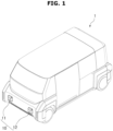
- FIG. 1 is a perspective view of a vehicle including a media module according to an embodiment of the present disclosure.
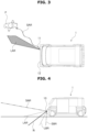
- FIG. 2 is a perspective view illustrating the state in which a pedestrian is present around the vehicle according to an embodiment of the present disclosure.
- FIG. 3 is a plan view illustrating the state in which a pedestrian is present around the vehicle according to an embodiment of the present disclosure.
- FIG. 4 is a side view of the vehicle according to an embodiment of the present disclosure.
- FIG. 5 is a perspective view of the media module according to an embodiment of the present disclosure.
- FIG. 6 is a side view of the media module according to an embodiment of the present disclosure.
- FIG. 7 is a plan view of the media module according to an embodiment of the present disclosure.
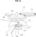
- FIG. 8 is a perspective view illustrating the state in which a module gear unit has been rotated in the media module according to an embodiment of the present disclosure.
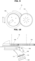
- FIG. 9 is a plan view illustrating the state in which the module gear unit has been rotated in the media module according to an embodiment of the present disclosure.
- FIG. 10 is a side view illustrating the state in which a reflection plate has been rotated with respect to the module gear unit in the media module according to an embodiment of the present disclosure.
- FIG. 11 is a side view illustrating the state in which a speaker has been rotated with respect to a reflection plate in the media module according to an embodiment of the present disclosure.
- FIG. 12 is a block diagram of the media module according to an embodiment of the present disclosure.
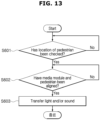
- FIG. 13 is a flowchart of a method of controlling the media module according to an embodiment of the present disclosure.
- a vehicle 1 may include a media module 10.
- the media module 10 may be disposed in the vehicle 1, may transmit light including a lighting signal in several directions, such as the front, side, rear, and upward of the vehicle 1, and may transmit a sound including an acoustic signal in several directions, such as the front, side, rear, and upward of the vehicle 1.
- a sensor S of the media module 10 may measure whether a pedestrian P is present around the vehicle 1 and a location of the pedestrian P when the pedestrian P is present.
- a controller C of the media module 10 may control operations of various devices of the media module 10 based on information measured by the sensor S.
- the sensor S and the controller C may be provided in the media module 10.
- a sensor and controller of another device not the media module 10 may be used as the sensor S and the controller C.
- the pedestrian P includes all of objects capable of receiving signal information transmitted by the vehicle, such as a two-wheeler rider, in addition to the pedestrian.
- the sensor S may be constructed as various types of sensors, including a camera, an infrared camera, RADAR, LiDAR, and an ultrasonic sensor.
- the controller C may control the media module 10 to emit light and/or an acoustic signal toward the pedestrian, based on a checked relative location between the vehicle 1 and the pedestrian P.
- the media module 10 may include a first media module 11 and a second media module 12.
- the first media module 11 and the second media module 12 may be disposed on the right and left sides of the vehicle 10, respectively.
- Detailed constructions of the first media module 11 and the second media module 12 may be the same.
- the sensor S may detect a location of the pedestrian P.
- the controller C may check a relative location between the detected location of the pedestrian P and the vehicle 1 through the sensor S.
- the controller C may control various devices of the media module 10, may generate light and a sound, and may transmit the light and sound toward the pedestrian P.
- the path of light before being reflected by a reflection plate 130 after being generated by a light-emitting device 110 is defined as a "light path before reflection (LBR)".
- the path of light that is generated by the light-emitting device 110 and then reflected by the reflection plate 130 is defined as a "light path after reflection (LAR)”.
- the path of a sound before being reflected by the reflection plate 130 after being generated by a speaker 120 is defined as a "sound path before reflection (SBR)”.
- SBR sound path before reflection
- SAR sound path after reflection
- the LAR may be directed toward the surface of the earth.
- the SAR may be directed toward the face of the pedestrian P, in particular, the ear of the pedestrian P.
- the pedestrian P may recognize light that is reflected by the surface of the earth, and may listen to a sound toward his or her face. Accordingly, the pedestrian P may recognize information, such as the presence of the vehicle 1 or the direction of progress.
- light that is generated by the media module 10 may be radiated toward the surface of the earth between the pedestrian P and the vehicle 1.
- Light that is generated by the media module 10 may be radiated toward the front (e.g., ahead of the feet of the pedestrian P) of the pedestrian P.
- the pedestrian P can receive information (e.g., the direction of progress and whether the vehicle moves) on the vehicle 1 through the light radiated to the surface of the earth in the form of visual information. Accordingly, the pedestrian P can be aware that the signal that is generated by the vehicle 1 is a message toward the pedestrian P himself or herself.
- a sound that is generated by the media module 10 may be transferred toward the pedestrian P.
- pedestrians other than the pedestrian P may listen to the sound low or may not listen to the sound. Accordingly, the pedestrian P can be aware that the signal that is generated by the vehicle 1 is a message toward the pedestrian P himself or herself. Furthermore, the sound may not act on another pedestrian other than the pedestrian P as noise pollution.
- the normal N of the virtual line when from a point on the lower part of the reflection plate 130 to a point on the upper part of the reflection plate 130 is extended as a virtual line, the normal N of the virtual line, that is, the normal N of a reflection surface of the reflection plate 130, may be disposed so that the normal N is directed toward the surface of the earth.
- a sound and light that are generated by the media module 10 may be transferred toward the pedestrian P after being reflected by the reflection surface.
- a first incident angle that is formed by the normal N of the reflection surface and the LBR may be smaller than a second incident angle that is formed by the normal N of the reflection surface and the SBR on the basis of the normal N of the reflection surface by which the sound and light are reflected.
- the angle of reflection of the LAR may be smaller than the angle of reflection of the SAR.
- the SBR, the LBR, the SAR, and the LAR are described with reference to FIGS. 4 to 6 .
- the media module 10 may include a module gear unit 100, the light-emitting device 110, the speaker 120, and the reflection plate 130.
- the module gear unit 100 may be rotatably installed in the vehicle body, for example, a module housing (MH) on which the media module 10 is mounted.
- the module gear unit 100 may be directly coupled to a motor (M), and may be rotated by the rotational driving of the motor M.
- the media module 10 may further include a rotation driving gear 101.
- the rotation driving gear 101 is engaged with the module gear unit 100, and provides the module gear unit 100 with rotation power provided by the motor M. Accordingly, as the rotation driving gear 101 is rotated by the rotational driving of the motor M, the module gear unit 100 may also be rotated. Accordingly, the SAR and the LAR may be changed from side to side.
- the media module 10 may further include the sensor S and the controller C.
- the sensor S measures a location of the pedestrian P around the vehicle 1.
- the controller C controls various operations of the media module 10, including a rotational operation of the module gear unit 100, based on information on a location of the pedestrian P, which is measured by the sensor S.
- the sensor S may be set to measure a location of the pedestrian P within a set distance area, when measuring the location of the pedestrian P around the vehicle 1.
- the module gear unit 100 may be connected to the reflection plate 130 on the lower side thereof.
- the module gear unit 100 may include a gear part engaged with the rotation driving gear 101 on the upper side thereof, and may include a connection part connected to the reflection plate 130 under the gear part.
- Angles that are formed by the module gear unit 100 and the reflection plate 130 may be fixed as in FIG. 6 . Furthermore, the angles that are formed by the module gear unit 100 and the reflection plate 130 may be adjusted as in FIG. 10 . That is, the reflection plate 130 may be constructed to be rotated with respect to the module gear unit 100.
- the reflection plate 130 When the reflection plate 130 is rotated with respect to the module gear unit 100 as in FIG. 10 , the speaker 120 and the light-emitting device 110 that are connected to the reflection plate 130 are also rotated with respect to the module gear unit 100. Accordingly, the SAR and the LAR may be changed. That is, the SAR and the LAR may be adjusted on the basis of the pedestrian P who is located farther from or closer to the vehicle 1, which is a target.
- the speaker 120 generates a sound including an acoustic signal.
- the sound generated by the speaker 120 is incident toward the reflection plate 130.
- the sound reflected by the reflection plate 130 is transmitted toward the place toward which the reflection plate 130 is directed.
- the speaker 120 may be disposed to face the reflection surface of the reflection plate 130.
- the speaker 120 may be directly connected to the reflection plate 130, and may be connected to the reflection plate 130 by another member or another method.
- Angles that are formed by the speaker 120 and the reflection plate 130 may be fixed as in FIG. 6 . Furthermore, the angles that are formed by the speaker 120 and the reflection plate 130 may be adjusted as in FIG. 11 . That is, the speaker 120 may be constructed to be rotated with respect to the reflection plate 130 through the axis of rotation H. Accordingly, the SAR may be changed. That is, the SAR may be adjusted on the basis of the pedestrian P who is located farther from or closer to the vehicle 1, which is a target.
- the light-emitting device 110 generates light including a lighting signal. Light that is generated by the light-emitting device 110 is incident toward the reflection plate 130. Light reflected by the reflection plate 130 is transmitted toward the place toward which the reflection plate 130 is directed.
- the light-emitting device 110 may be disposed to face the reflection surface of the reflection plate 130.
- the light-emitting device 110 may be directly connected to the reflection plate 130, and may be connected to the reflection plate 130 by another member or another method.
- FIG. 5 illustrates an example in which the light-emitting device 110 is indirectly coupled to the reflection plate 130 through the speaker 120 as the light-emitting device 110 is connected to the speaker 120 by a fixing member 111.
- a method of coupling the light-emitting device 110 and the reflection plate 130 is not limited to the example.
- Angles that are formed by the light-emitting device 110 and the reflection plate 130 may be fixed as in FIG. 6 . Furthermore, the angles that are formed by the light-emitting device 110 and the reflection plate 130 may be adjusted as in FIG. 11 . That is, the light-emitting device 110 may be constructed to be rotated with respect to the reflection plate 130 through the axis of rotation H. Accordingly, the LAR may be changed. That is, the LAR may be adjusted on the basis of the pedestrian P who is located farther from or closer to the vehicle 1, which is a target.
- a point at which light generated by the light-emitting device 110 is reflected by the reflection plate 130 and a point at which a sound generated by the speaker 120 is reflected by the reflection plate 130 may be the same or may be different from each other.
- An internal surface of the reflection plate 130 by which light and the sound are reflected may be formed to have a curved surface.
- the LBR of light generated by the light-emitting device 110 and the SBR of a sound generated by the speaker 120 are incident on the reflection plate 130 at different incident angles. Accordingly, the directions toward which the light and the sound are directed are different from each other.
- the LAR of light generated by the light-emitting device 110 may be directed toward the surface of the earth.
- the SAR of a sound generated by the speaker 120 may be directed toward the pedestrian not the surface of the earth.
- the LAR when an angle that is formed by the LBR and the normal N of the reflection surface is smaller than an angle that is formed by the SBR and the normal N of the reflection surface, the LAR may be directed toward the surface of the earth, and the SAR may be directed toward the ground.
- the module gear unit 100 may be constructed to be engaged with the rotation driving gear 101.
- the module gear unit 100 may be rotated by the rotation of the rotation driving gear 101.
- the module gear unit 100 When the rotation driving gear 101 is rotated counterclockwise, the module gear unit 100 may be rotated clockwise. Furthermore, when the rotation driving gear 101 is rotated clockwise, the module gear unit 100 may be rotated counterclockwise.
- the directions of the SAR and the LAR may be changed, and a signal may be transmitted toward the pedestrian P, that is, a target. Accordingly, visual and auditory pollution may not act on another pedestrian other than the pedestrian P. Furthermore, a signal can be accurately transmitted to the pedestrian P, that is, a target.
- the reflection plate 130 may be constructed to be rotated with respect to the module gear unit 100.
- the light-emitting device 110 and the speaker 120 are connected to the module gear unit 100 through the reflection plate 130. Accordingly, when the reflection plate 130 is rotated, both the light-emitting device 110 and the speaker 120 may be rotated at the same angle.
- the light-emitting device 110, the speaker 120, and the reflection plate 130 are constructed to be rotated perpendicularly to the module gear unit 100, the direction of the SAR of a sound that is generated by the speaker 120 and reflected by the reflection plate 130 and/or the direction of the LAR of light that is generated by the light-emitting device 110 and reflected by the reflection plate 130 may be changed. Accordingly, light and/or a sound can be accurately transmitted to the pedestrian P who is located at a distance far from the vehicle 1 or at a distance close to the vehicle 1.
- the module gear unit 100 and the reflection plate 130 may be connected by a length adjustment member 140.
- an angle at which the reflection plate 130 has been installed with respect to the module gear unit 100 may be adjusted. Accordingly, an angle that is formed by the reflection plate 130 and the module gear unit 100 in FIG. 10 may be greater or smaller than an angle that is formed by the reflection plate 130 and the module gear unit 100 in FIG. 6 .
- the length adjustment member 140 may have rotation shafts at a portion at which the length adjustment member 140 is connected to the module gear unit 100 and a portion at which the length adjustment member 140 is connected to the reflection plate 130. An operation of the length adjustment member 140 may be controlled by the controller C.
- the light-emitting device 110 and/or the speaker 120 may be constructed to be rotated or moved with respect to the reflection plate 130.
- the speaker 120 may be rotatably connected to the reflection plate 130 through the axis of rotation H.
- the light-emitting device 110 is connected to the speaker 120. Accordingly, when the speaker 120 is rotated with respect to the reflection plate 130, the light-emitting device 110 may also be rotated at the same angle as the speaker 120.
- the direction of the SAR of a sound that is generated by the speaker 120 and reflected by the reflection plate 130 and/or the direction of the LAR of light that is generated by the light-emitting device 110 and reflected by the reflection plate 130 may be changed.
- the speaker 120 is rotatably connected to the reflection plate 130 through the axis of rotation H, but may be rotatably or movably connected to the reflection plate 130 through the length adjustment member 140 illustrated in FIG. 10 . Accordingly, the speaker 120 and the light-emitting device 110 may be movably adjusted with respect to the reflection plate 130, so that the SAR and the LAR can be adjusted.
- the speaker 120 may be equipped with a motor (not illustrated) in order to provide rotation power having the axis of rotation H as its center of rotation.
- An operation of the motor or an operation of the length adjustment member 140 may be controlled by the controller C.
- the angles at which the speaker 120 and the reflection plate 130 are installed are adjusted, that is, since the location of a reflection point of the reflection plate 130 by which a sound is reflected is changed, the direction of the SAR of a sound that is generated by the speaker 120 and reflected by the reflection plate 130 can be adjusted.
- the angles at which the light-emitting device 110 and the reflection plate 130 are installed are adjusted, that is, since the location of a reflection point of the reflection plate 130 by which light is reflected is changed, the direction of the LAR of light that is generated by the light-emitting device 110 and reflected by the reflection plate 130 can be adjusted.
- the method of controlling the media module includes a step of checking a location of the pedestrian P around the vehicle 1 through the sensor S, a step of aligning the media module 10 and the pedestrian P based on information on the location of the pedestrian P, which is measured by the sensor S, so that the media module 10 is directed toward the pedestrian P, and a step of transmitting at least one of light and a sound toward the pedestrian P by controlling the media module 10.
- the controller C may control the sensor S to detect the pedestrian P around the vehicle 1.
- the controller C may calculate a relative location between the pedestrian P detected by the sensor S and the vehicle 1 (S601).
- the controller C may continuously measure whether the pedestrian P is present within the predetermined range through the sensor S.
- the controller C may align the media module 10 and the pedestrian P so that light that is generated by the light-emitting device 110 and a sound that is generated by the speaker 120 are directed toward the pedestrian P (S602).
- the step of aligning the media module 10 and the pedestrian P so that the media module 10 is directed toward the pedestrian P may include a step of rotating, by the controller C, the module gear unit 100 so that at least one of light that is reflected by the reflection plate 130 and a sound that is reflected by the reflection plate 130 is directed toward the pedestrian P.
- the controller C may control a rotational operation of the module gear unit 100 through the motor M and the rotation driving gear 101, or may directly control a rotational operation of the module gear unit 100 through the motor M. Accordingly, the media module 10 can be aligned so that the media module 10 is directed toward the pedestrian P.
- the step of aligning the media module 10 and the pedestrian P so that the media module 10 is directed toward the pedestrian P may further include a step of rotating, by the controller C, the reflection plate 130 with respect to the module gear unit 100.
- the step of aligning the media module 10 and the pedestrian P so that the media module 10 is directed toward the pedestrian P may further include a step of rotating, by the controller C, the light-emitting device 110 and the speaker 120 with respect to the reflection plate 130.
- the controller C may control operations of the light-emitting device 110, the speaker 120, and the reflection plate 130.
- Operational control of the controller C includes all of a series of operations, such as an operation of generating light from the light-emitting device 110 and generating a sound from the speaker 120 and an operation of rotating or moving the light-emitting device 110, the speaker 120, and the reflection plate 130.
- the controller C may control operations of the module gear unit 100 and the length adjustment member 140.
- the controller C may control the light-emitting device 110 and the speaker 120 to generate light and a sound and to transmit the light and the sound toward the pedestrian P (S603).
- a signal from a vehicle rider can be accurately transferred to the pedestrian P, that is, a target, and image pollution and noise pollution may not act on another pedestrian that is not a target.
Landscapes
- Engineering & Computer Science (AREA)
- Mechanical Engineering (AREA)
- Physics & Mathematics (AREA)
- Acoustics & Sound (AREA)
- General Engineering & Computer Science (AREA)
- Fittings On The Vehicle Exterior For Carrying Loads, And Devices For Holding Or Mounting Articles (AREA)
- Lighting Device Outwards From Vehicle And Optical Signal (AREA)
Abstract
Description
- Exemplary embodiments of the present disclosure relate to a media module, a method of controlling the media module, and a vehicle including the media module, and more particularly, to a media module capable of transferring visual and/or audible signals to a pedestrian, a method of controlling the media module, and a vehicle including the media module.
- In general, various types of lighting devices for easily checking an object disposed around a vehicle when the vehicle travels and notifying a surrounding vehicle or a pedestrian of a state of the vehicle or transferring a signal to a surrounding vehicle or a pedestrian are installed in the vehicle.
- However, a common lighting device has problems in that the type of a signal which may be transmitted is limited because the signal is transferred through only the turn-on and turn-off of an LED and it is difficult to transfer a clear and accurate signal because only a rather flat image can be transmitted. Furthermore, in the daytime in which an illuminance value outside a vehicle is high, the common lighting device has a problem in that visibility is low in the transfer of a signal by only the turn-on and turn-off of an LED.
- The Background technology of the present disclosure was disclosed in
Korean Patent No. 10-1789652 (registered on October 18, 2017 - Various embodiments are directed to a media module capable of transmitting a lighting signal and an acoustic signal which may be directed toward a pedestrian, a method of controlling the media module, and a vehicle including the media module.
- However, an object to be solved by the present disclosure is not limited to the aforementioned object, and may be variously extended without departing from the spirit and scope of the present disclosure.
- In an embodiment, a media module may include a module gear unit rotatably installed in a vehicle body, a reflection plate connected to the module gear unit, a light-emitting device disposed to face a reflection surface of the reflection plate, and a speaker disposed to face the reflection surface of the reflection plate, wherein light generated by the light-emitting device may be incident toward the reflection plate, and a sound generated by the speaker may be incident toward the reflection plate.
- The media module may further include a rotation driving gear engaged with the module gear unit and configured to provide rotation power to the module gear unit.
- A first incident angle that is formed by the light that is incident toward the reflection plate and a normal of the reflection plate may be different from a second incident angle that is formed by the sound that is incident toward the reflection plate and the normal of the reflection plate.
- The first incident angle may be smaller than the second incident angle.
- An internal surface of the reflection plate by which the light and the sound are reflected may be formed to have a curved surface.
- The reflection plate may be rotatable with respect to the module gear unit.
- The light-emitting device and the speaker may be rotatable with respect to the reflection plate.
- The light-emitting device and the speaker may be movable with respect to the reflection plate.
- The media module may further include a sensor configured to measure a location of a pedestrian around a vehicle and a controller configured to control a rotational operation of the module gear unit based on information on the location of the pedestrian, which has been measured by the sensor.
- In an embodiment, a method of controlling a media module may include checking, by a sensor, a location of a pedestrian around a vehicle, aligning the media module and the pedestrian based on information on the location of the pedestrian, which has been measured by the sensor, so that the media module is directed toward the pedestrian, and controlling the media module to transmit at least one of light and a sound toward the pedestrian.
- The media module may include a module gear unit rotatably installed in a vehicle body, a reflection plate connected to the module gear unit, a light-emitting device disposed to face a reflection surface of the reflection plate, and a speaker disposed to face the reflection surface of the reflection plate, wherein the light generated by the light-emitting device may be incident toward the reflection plate, and the sound generated by the speaker may be incident toward the reflection plate.
- The media module may further include a controller configured to control a rotational operation of the module gear unit. The aligning of the media module and the pedestrian so that the media module is directed toward the pedestrian may include rotating, by the controller, the module gear unit so that at least one of the light reflected by the reflection plate and the sound reflected by the reflection plate is directed toward the pedestrian.
- A first incident angle that is formed by the light that is incident toward the reflection plate and a normal of the reflection plate may be different from a second incident angle that is formed by the sound that is incident toward the reflection plate and the normal of the reflection plate.
- The aligning of the media module and the pedestrian so that the media module is directed toward the pedestrian may further include rotating, by the controller, the reflection plate with respect to the module gear unit.
- The aligning of the media module and the pedestrian so that the media module is directed toward the pedestrian may further include rotating, by the controller, the light-emitting device and the speaker with respect to the reflection plate.
- In an embodiment, a vehicle may include a media module. The media module may include a module gear unit rotatably installed in a vehicle body, a reflection plate connected to the module gear unit, a light-emitting device disposed to face a reflection surface of the reflection plate, a speaker disposed to face the reflection surface of the reflection plate, a sensor configured to measure a location of a pedestrian around a vehicle, and a controller configured to control a rotational operation of the module gear unit based on information on the location of the pedestrian, which has been measured by the sensor, wherein at least one of light and a sound may be transmitted toward the pedestrian by controlling the media module.
- According to the present disclosure, the media module can accurately transfer a signal of a vehicle to a targeted pedestrian because the media module transmits light and/or a sound toward the targeted pedestrian. Accordingly, driving stability can be improved and the safety of a pedestrian can be secured, through communication between the vehicle and the pedestrian.
- According to the present disclosure, image pollution and/or noise pollution may not act on another pedestrian that is not a target because a signal of a vehicle can be transferred to a targeted pedestrian in the form of light and/or a sound.
-
-
FIG. 1 is a perspective view of a vehicle including a media module according to an embodiment of the present disclosure. -
FIG. 2 is a perspective view illustrating the state in which a pedestrian is present around the vehicle according to an embodiment of the present disclosure. -
FIG. 3 is a plan view illustrating the state in which a pedestrian is present around the vehicle according to an embodiment of the present disclosure. -
FIG. 4 is a side view of the vehicle according to an embodiment of the present disclosure. -
FIG. 5 is a perspective view of the media module according to an embodiment of the present disclosure. -
FIG. 6 is a side view of the media module according to an embodiment of the present disclosure. -
FIG. 7 is a plan view of the media module according to an embodiment of the present disclosure. -
FIG. 8 is a perspective view illustrating the state in which a module gear unit has been rotated in the media module according to an embodiment of the present disclosure. -
FIG. 9 is a plan view illustrating the state in which the module gear unit has been rotated in the media module according to an embodiment of the present disclosure. -
FIG. 10 is a side view illustrating the state in which a reflection plate has been rotated with respect to the module gear unit in the media module according to an embodiment of the present disclosure. -
FIG. 11 is a side view illustrating the state in which a speaker has been rotated with respect to a reflection plate in the media module according to an embodiment of the present disclosure. -
FIG. 12 is a block diagram of the media module according to an embodiment of the present disclosure. -
FIG. 13 is a flowchart of a method of controlling the media module according to an embodiment of the present disclosure. - Hereinafter, a media module, a method of controlling the media module, and a vehicle including the media module will be described below with reference to the accompanying drawings through various exemplary embodiments.
- In this process, the thicknesses of lines or the sizes of elements illustrated in the drawings may have been exaggerated for the clarity of a description and for convenience' sake. Furthermore, terms to be described below have been defined by taking into consideration their functions in the present disclosure, and may be changed depending on a user or operator's intention or practice. Accordingly, such terms should be defined based on the overall contents of this specification.
- Furthermore, throughout the specification, when it is described that one part is "connected (or coupled)" to another part, the one part may be "directly connected (or coupled)" to the another part or may be "indirectly connected (or coupled)" to the another part with another member interposed therebetween. When it is said that one component "includes (or comprises)" the other element, this means that the one component may further "include (or comprise)" another element not the exclusion of another element unless explicitly described to the contrary.
- Furthermore, throughout this specification, the same reference numerals may denote the same elements. Although not mentioned or described in a specific drawing, the same reference numerals or similar reference numerals may be described on the basis of another drawing. Furthermore, although a reference numeral is not indicated in a portion of a specific drawing, the portion may be described on the basis of another drawing. Furthermore, the number, shapes, and sizes of detailed elements included in the drawings of this application, a relative difference between the sizes, etc. have been set for convenience of understanding, and do not limit embodiments, and may be implemented in various forms.
-
FIG. 1 is a perspective view of a vehicle including a media module according to an embodiment of the present disclosure.FIG. 2 is a perspective view illustrating the state in which a pedestrian is present around the vehicle according to an embodiment of the present disclosure.FIG. 3 is a plan view illustrating the state in which a pedestrian is present around the vehicle according to an embodiment of the present disclosure.FIG. 4 is a side view of the vehicle according to an embodiment of the present disclosure.FIG. 5 is a perspective view of the media module according to an embodiment of the present disclosure.FIG. 6 is a side view of the media module according to an embodiment of the present disclosure.FIG. 7 is a plan view of the media module according to an embodiment of the present disclosure.FIG. 8 is a perspective view illustrating the state in which a module gear unit has been rotated in the media module according to an embodiment of the present disclosure.FIG. 9 is a plan view illustrating the state in which the module gear unit has been rotated in the media module according to an embodiment of the present disclosure.FIG. 10 is a side view illustrating the state in which a reflection plate has been rotated with respect to the module gear unit in the media module according to an embodiment of the present disclosure.FIG. 11 is a side view illustrating the state in which a speaker has been rotated with respect to a reflection plate in the media module according to an embodiment of the present disclosure.FIG. 12 is a block diagram of the media module according to an embodiment of the present disclosure.FIG. 13 is a flowchart of a method of controlling the media module according to an embodiment of the present disclosure. - Referring to
FIGS. 1 to 13 , avehicle 1 according to an embodiment of the present disclosure may include amedia module 10. Themedia module 10 may be disposed in thevehicle 1, may transmit light including a lighting signal in several directions, such as the front, side, rear, and upward of thevehicle 1, and may transmit a sound including an acoustic signal in several directions, such as the front, side, rear, and upward of thevehicle 1. - A sensor S of the
media module 10 may measure whether a pedestrian P is present around thevehicle 1 and a location of the pedestrian P when the pedestrian P is present. A controller C of themedia module 10 may control operations of various devices of themedia module 10 based on information measured by the sensor S. The sensor S and the controller C may be provided in themedia module 10. A sensor and controller of another device not themedia module 10 may be used as the sensor S and the controller C. In this case, the pedestrian P includes all of objects capable of receiving signal information transmitted by the vehicle, such as a two-wheeler rider, in addition to the pedestrian. - The sensor S may be constructed as various types of sensors, including a camera, an infrared camera, RADAR, LiDAR, and an ultrasonic sensor.
- The controller C may control the
media module 10 to emit light and/or an acoustic signal toward the pedestrian, based on a checked relative location between thevehicle 1 and the pedestrian P. - The
media module 10 may include afirst media module 11 and asecond media module 12. Thefirst media module 11 and thesecond media module 12 may be disposed on the right and left sides of thevehicle 10, respectively. Detailed constructions of thefirst media module 11 and thesecond media module 12 may be the same. - The sensor S may detect a location of the pedestrian P. The controller C may check a relative location between the detected location of the pedestrian P and the
vehicle 1 through the sensor S. - The controller C may control various devices of the
media module 10, may generate light and a sound, and may transmit the light and sound toward the pedestrian P. - In the following description, the path of light before being reflected by a
reflection plate 130 after being generated by a light-emittingdevice 110 is defined as a "light path before reflection (LBR)". The path of light that is generated by the light-emittingdevice 110 and then reflected by thereflection plate 130 is defined as a "light path after reflection (LAR)". The path of a sound before being reflected by thereflection plate 130 after being generated by aspeaker 120 is defined as a "sound path before reflection (SBR)". The path of a sound that is generated by thespeaker 120 and then reflected by thereflection plate 130 is defined as a "sound path after reflection (SAR)". - The LAR may be directed toward the surface of the earth. The SAR may be directed toward the face of the pedestrian P, in particular, the ear of the pedestrian P. The pedestrian P may recognize light that is reflected by the surface of the earth, and may listen to a sound toward his or her face. Accordingly, the pedestrian P may recognize information, such as the presence of the
vehicle 1 or the direction of progress. - Referring to
FIG. 3 , light that is generated by themedia module 10 may be radiated toward the surface of the earth between the pedestrian P and thevehicle 1. Light that is generated by themedia module 10 may be radiated toward the front (e.g., ahead of the feet of the pedestrian P) of the pedestrian P. - As described above, as light is radiated toward the surface of the earth between the pedestrian P and the
vehicle 1, the pedestrian P can receive information (e.g., the direction of progress and whether the vehicle moves) on thevehicle 1 through the light radiated to the surface of the earth in the form of visual information. Accordingly, the pedestrian P can be aware that the signal that is generated by thevehicle 1 is a message toward the pedestrian P himself or herself. - Referring to
FIG. 4 , a sound that is generated by themedia module 10 may be transferred toward the pedestrian P. - As described above, as a sound is transferred toward the pedestrian P, in particular, the face of the pedestrian P, pedestrians other than the pedestrian P may listen to the sound low or may not listen to the sound. Accordingly, the pedestrian P can be aware that the signal that is generated by the
vehicle 1 is a message toward the pedestrian P himself or herself. Furthermore, the sound may not act on another pedestrian other than the pedestrian P as noise pollution. - Referring to
FIGS. 4 and5 , when from a point on the lower part of thereflection plate 130 to a point on the upper part of thereflection plate 130 is extended as a virtual line, the normal N of the virtual line, that is, the normal N of a reflection surface of thereflection plate 130, may be disposed so that the normal N is directed toward the surface of the earth. - A sound and light that are generated by the
media module 10 may be transferred toward the pedestrian P after being reflected by the reflection surface. A first incident angle that is formed by the normal N of the reflection surface and the LBR may be smaller than a second incident angle that is formed by the normal N of the reflection surface and the SBR on the basis of the normal N of the reflection surface by which the sound and light are reflected. - Accordingly, the angle of reflection of the LAR may be smaller than the angle of reflection of the SAR. The SBR, the LBR, the SAR, and the LAR are described with reference to
FIGS. 4 to 6 . - Referring to
FIGS. 5 to 7 , themedia module 10 according to an embodiment of the present disclosure may include amodule gear unit 100, the light-emittingdevice 110, thespeaker 120, and thereflection plate 130. - The
module gear unit 100 may be rotatably installed in the vehicle body, for example, a module housing (MH) on which themedia module 10 is mounted. Themodule gear unit 100 may be directly coupled to a motor (M), and may be rotated by the rotational driving of the motor M. - The
media module 10 according to an embodiment of the present disclosure may further include arotation driving gear 101. Therotation driving gear 101 is engaged with themodule gear unit 100, and provides themodule gear unit 100 with rotation power provided by the motor M. Accordingly, as therotation driving gear 101 is rotated by the rotational driving of the motor M, themodule gear unit 100 may also be rotated. Accordingly, the SAR and the LAR may be changed from side to side. - The
media module 10 may further include the sensor S and the controller C. The sensor S measures a location of the pedestrian P around thevehicle 1. The controller C controls various operations of themedia module 10, including a rotational operation of themodule gear unit 100, based on information on a location of the pedestrian P, which is measured by the sensor S. The sensor S may be set to measure a location of the pedestrian P within a set distance area, when measuring the location of the pedestrian P around thevehicle 1. - The
module gear unit 100 may be connected to thereflection plate 130 on the lower side thereof. Themodule gear unit 100 may include a gear part engaged with therotation driving gear 101 on the upper side thereof, and may include a connection part connected to thereflection plate 130 under the gear part. - Angles that are formed by the
module gear unit 100 and thereflection plate 130 may be fixed as inFIG. 6 . Furthermore, the angles that are formed by themodule gear unit 100 and thereflection plate 130 may be adjusted as inFIG. 10 . That is, thereflection plate 130 may be constructed to be rotated with respect to themodule gear unit 100. - When the
reflection plate 130 is rotated with respect to themodule gear unit 100 as inFIG. 10 , thespeaker 120 and the light-emittingdevice 110 that are connected to thereflection plate 130 are also rotated with respect to themodule gear unit 100. Accordingly, the SAR and the LAR may be changed. That is, the SAR and the LAR may be adjusted on the basis of the pedestrian P who is located farther from or closer to thevehicle 1, which is a target. - The
speaker 120 generates a sound including an acoustic signal. The sound generated by thespeaker 120 is incident toward thereflection plate 130. The sound reflected by thereflection plate 130 is transmitted toward the place toward which thereflection plate 130 is directed. - The
speaker 120 may be disposed to face the reflection surface of thereflection plate 130. Thespeaker 120 may be directly connected to thereflection plate 130, and may be connected to thereflection plate 130 by another member or another method. - Angles that are formed by the
speaker 120 and thereflection plate 130 may be fixed as inFIG. 6 . Furthermore, the angles that are formed by thespeaker 120 and thereflection plate 130 may be adjusted as inFIG. 11 . That is, thespeaker 120 may be constructed to be rotated with respect to thereflection plate 130 through the axis of rotation H. Accordingly, the SAR may be changed. That is, the SAR may be adjusted on the basis of the pedestrian P who is located farther from or closer to thevehicle 1, which is a target. - The light-emitting
device 110 generates light including a lighting signal. Light that is generated by the light-emittingdevice 110 is incident toward thereflection plate 130. Light reflected by thereflection plate 130 is transmitted toward the place toward which thereflection plate 130 is directed. - The light-emitting
device 110 may be disposed to face the reflection surface of thereflection plate 130. The light-emittingdevice 110 may be directly connected to thereflection plate 130, and may be connected to thereflection plate 130 by another member or another method.FIG. 5 illustrates an example in which the light-emittingdevice 110 is indirectly coupled to thereflection plate 130 through thespeaker 120 as the light-emittingdevice 110 is connected to thespeaker 120 by a fixingmember 111. However, as described above, a method of coupling the light-emittingdevice 110 and thereflection plate 130 is not limited to the example. - Angles that are formed by the light-emitting
device 110 and thereflection plate 130 may be fixed as inFIG. 6 . Furthermore, the angles that are formed by the light-emittingdevice 110 and thereflection plate 130 may be adjusted as inFIG. 11 . That is, the light-emittingdevice 110 may be constructed to be rotated with respect to thereflection plate 130 through the axis of rotation H. Accordingly, the LAR may be changed. That is, the LAR may be adjusted on the basis of the pedestrian P who is located farther from or closer to thevehicle 1, which is a target. - A point at which light generated by the light-emitting
device 110 is reflected by thereflection plate 130 and a point at which a sound generated by thespeaker 120 is reflected by thereflection plate 130 may be the same or may be different from each other. An internal surface of thereflection plate 130 by which light and the sound are reflected may be formed to have a curved surface. - The LBR of light generated by the light-emitting
device 110 and the SBR of a sound generated by thespeaker 120 are incident on thereflection plate 130 at different incident angles. Accordingly, the directions toward which the light and the sound are directed are different from each other. - Accordingly, the LAR of light generated by the light-emitting
device 110 may be directed toward the surface of the earth. The SAR of a sound generated by thespeaker 120 may be directed toward the pedestrian not the surface of the earth. - For example, when an angle that is formed by the LBR and the normal N of the reflection surface is smaller than an angle that is formed by the SBR and the normal N of the reflection surface, the LAR may be directed toward the surface of the earth, and the SAR may be directed toward the ground.
- Referring to
FIGS. 8 and9 , themodule gear unit 100 may be constructed to be engaged with therotation driving gear 101. Themodule gear unit 100 may be rotated by the rotation of therotation driving gear 101. - When the
rotation driving gear 101 is rotated counterclockwise, themodule gear unit 100 may be rotated clockwise. Furthermore, when therotation driving gear 101 is rotated clockwise, themodule gear unit 100 may be rotated counterclockwise. - As the
module gear unit 100 is rotated, the directions of the SAR and the LAR may be changed, and a signal may be transmitted toward the pedestrian P, that is, a target. Accordingly, visual and auditory pollution may not act on another pedestrian other than the pedestrian P. Furthermore, a signal can be accurately transmitted to the pedestrian P, that is, a target. - Referring to
FIG. 10 , in themedia module 10, thereflection plate 130 may be constructed to be rotated with respect to themodule gear unit 100. The light-emittingdevice 110 and thespeaker 120 are connected to themodule gear unit 100 through thereflection plate 130. Accordingly, when thereflection plate 130 is rotated, both the light-emittingdevice 110 and thespeaker 120 may be rotated at the same angle. - As the light-emitting
device 110, thespeaker 120, and thereflection plate 130 are constructed to be rotated perpendicularly to themodule gear unit 100, the direction of the SAR of a sound that is generated by thespeaker 120 and reflected by thereflection plate 130 and/or the direction of the LAR of light that is generated by the light-emittingdevice 110 and reflected by thereflection plate 130 may be changed. Accordingly, light and/or a sound can be accurately transmitted to the pedestrian P who is located at a distance far from thevehicle 1 or at a distance close to thevehicle 1. - According to an embodiment, the
module gear unit 100 and thereflection plate 130 may be connected by alength adjustment member 140. As the length of thelength adjustment member 140 is changed, an angle at which thereflection plate 130 has been installed with respect to themodule gear unit 100 may be adjusted. Accordingly, an angle that is formed by thereflection plate 130 and themodule gear unit 100 inFIG. 10 may be greater or smaller than an angle that is formed by thereflection plate 130 and themodule gear unit 100 inFIG. 6 . Thelength adjustment member 140 may have rotation shafts at a portion at which thelength adjustment member 140 is connected to themodule gear unit 100 and a portion at which thelength adjustment member 140 is connected to thereflection plate 130. An operation of thelength adjustment member 140 may be controlled by the controller C. - Referring to
FIG. 11 , the light-emittingdevice 110 and/or thespeaker 120 may be constructed to be rotated or moved with respect to thereflection plate 130. Thespeaker 120 may be rotatably connected to thereflection plate 130 through the axis of rotation H. The light-emittingdevice 110 is connected to thespeaker 120. Accordingly, when thespeaker 120 is rotated with respect to thereflection plate 130, the light-emittingdevice 110 may also be rotated at the same angle as thespeaker 120. - As the light-emitting
device 110 and/or thespeaker 120 are constructed to be rotated or moved with respect to thereflection plate 130, the direction of the SAR of a sound that is generated by thespeaker 120 and reflected by thereflection plate 130 and/or the direction of the LAR of light that is generated by the light-emittingdevice 110 and reflected by thereflection plate 130 may be changed. - Accordingly, light and/or a sound can be accurately transmitted to the pedestrian P, that is, a target, based on a distance between the
vehicle 1 and the pedestrian P. - In
FIG. 11 , thespeaker 120 is rotatably connected to thereflection plate 130 through the axis of rotation H, but may be rotatably or movably connected to thereflection plate 130 through thelength adjustment member 140 illustrated inFIG. 10 . Accordingly, thespeaker 120 and the light-emittingdevice 110 may be movably adjusted with respect to thereflection plate 130, so that the SAR and the LAR can be adjusted. - The
speaker 120 may be equipped with a motor (not illustrated) in order to provide rotation power having the axis of rotation H as its center of rotation. An operation of the motor or an operation of thelength adjustment member 140 may be controlled by the controller C. - Since the angles at which the
speaker 120 and thereflection plate 130 are installed are adjusted, that is, since the location of a reflection point of thereflection plate 130 by which a sound is reflected is changed, the direction of the SAR of a sound that is generated by thespeaker 120 and reflected by thereflection plate 130 can be adjusted. - Since the angles at which the light-emitting
device 110 and thereflection plate 130 are installed are adjusted, that is, since the location of a reflection point of thereflection plate 130 by which light is reflected is changed, the direction of the LAR of light that is generated by the light-emittingdevice 110 and reflected by thereflection plate 130 can be adjusted. - Referring to
FIG. 13 , the method of controlling the media module according to an embodiment of the present disclosure includes a step of checking a location of the pedestrian P around thevehicle 1 through the sensor S, a step of aligning themedia module 10 and the pedestrian P based on information on the location of the pedestrian P, which is measured by the sensor S, so that themedia module 10 is directed toward the pedestrian P, and a step of transmitting at least one of light and a sound toward the pedestrian P by controlling themedia module 10. - The controller C may control the sensor S to detect the pedestrian P around the
vehicle 1. The controller C may calculate a relative location between the pedestrian P detected by the sensor S and the vehicle 1 (S601). - When the pedestrian P is not detected within a predetermined range around the
vehicle 1, the controller C may continuously measure whether the pedestrian P is present within the predetermined range through the sensor S. When the pedestrian P is detected within the predetermined range around thevehicle 1, the controller C may align themedia module 10 and the pedestrian P so that light that is generated by the light-emittingdevice 110 and a sound that is generated by thespeaker 120 are directed toward the pedestrian P (S602). - The step of aligning the
media module 10 and the pedestrian P so that themedia module 10 is directed toward the pedestrian P may include a step of rotating, by the controller C, themodule gear unit 100 so that at least one of light that is reflected by thereflection plate 130 and a sound that is reflected by thereflection plate 130 is directed toward the pedestrian P. - The controller C may control a rotational operation of the
module gear unit 100 through the motor M and therotation driving gear 101, or may directly control a rotational operation of themodule gear unit 100 through the motor M. Accordingly, themedia module 10 can be aligned so that themedia module 10 is directed toward the pedestrian P. - The step of aligning the
media module 10 and the pedestrian P so that themedia module 10 is directed toward the pedestrian P may further include a step of rotating, by the controller C, thereflection plate 130 with respect to themodule gear unit 100. - The step of aligning the
media module 10 and the pedestrian P so that themedia module 10 is directed toward the pedestrian P may further include a step of rotating, by the controller C, the light-emittingdevice 110 and thespeaker 120 with respect to thereflection plate 130. - The controller C may control operations of the light-emitting
device 110, thespeaker 120, and thereflection plate 130. Operational control of the controller C includes all of a series of operations, such as an operation of generating light from the light-emittingdevice 110 and generating a sound from thespeaker 120 and an operation of rotating or moving the light-emittingdevice 110, thespeaker 120, and thereflection plate 130. For example, the controller C may control operations of themodule gear unit 100 and thelength adjustment member 140. - When determining that the
media module 10 and the pedestrian P have been aligned so that themedia module 10 is directed toward the pedestrian P, the controller C may control the light-emittingdevice 110 and thespeaker 120 to generate light and a sound and to transmit the light and the sound toward the pedestrian P (S603). - As described above, as the
media module 10 transmits light and a sound toward the pedestrian P, a signal from a vehicle rider can be accurately transferred to the pedestrian P, that is, a target, and image pollution and noise pollution may not act on another pedestrian that is not a target.
Claims (15)
- A media module comprising:a module gear unit rotatably installed in a vehicle body;a reflection plate connected to the module gear unit;a light-emitting device disposed to face a reflection surface of the reflection plate; anda speaker disposed to face the reflection surface of the reflection plate,wherein light generated by the light-emitting device is incident toward the reflection plate, and a sound generated by the speaker is incident toward the reflection plate.
- The media module of claim 1, further comprising a rotation driving gear engaged with the module gear unit and configured to provide rotation power to the module gear unit.
- The media module of claim 1, or 2, wherein a first incident angle that is formed by the light that is incident toward the reflection plate and a normal of the reflection plate is different from a second incident angle that is formed by the sound that is incident toward the reflection plate and the normal of the reflection plate.
- The media module of claim 3, wherein the first incident angle is smaller than the second incident angle.
- The media module of any one of claims 1 to 4, wherein an internal surface of the reflection plate by which the light and the sound are reflected is formed to have a curved surface.
- The media module of any one of claims 1 to 5, wherein the reflection plate is rotatable with respect to the module gear unit.
- The media module of any one of claims 1 to 6, wherein the light-emitting device and the speaker are rotatable with respect to the reflection plate.
- The media module of any one of claims 1 to 7, further comprising:a sensor configured to measure a location of a pedestrian around a vehicle; anda controller configured to control a rotational operation of the module gear unit based on information on the location of the pedestrian, which has been measured by the sensor.
- A method of controlling a media module, comprising:checking, by a sensor, a location of a pedestrian around a vehicle;aligning the media module and the pedestrian based on information on the location of the pedestrian, which has been measured by the sensor, so that the media module is directed toward the pedestrian; andcontrolling the media module to transmit at least one of light and a sound toward the pedestrian.
- The method of claim 9, wherein the media module comprises:a module gear unit rotatably installed in a vehicle body;a reflection plate connected to the module gear unit;a light-emitting device disposed to face a reflection surface of the reflection plate; anda speaker disposed to face the reflection surface of the reflection plate,wherein the light generated by the light-emitting device is incident toward the reflection plate, and the sound generated by the speaker is incident toward the reflection plate.
- The method of claim 10, wherein:the media module further comprises a controller configured to control a rotational operation of the module gear unit, andthe aligning of the media module and the pedestrian so that the media module is directed toward the pedestrian comprises rotating, by the controller, the module gear unit so that at least one of the light reflected by the reflection plate and the sound reflected by the reflection plate is directed toward the pedestrian.
- The method of claim 11, wherein a first incident angle that is formed by the light that is incident toward the reflection plate and a normal of the reflection plate is different from a second incident angle that is formed by the sound that is incident toward the reflection plate and the normal of the reflection plate.
- The method of claim 11, or 12, wherein the aligning of the media module and the pedestrian so that the media module is directed toward the pedestrian further comprises rotating, by the controller, the reflection plate with respect to the module gear unit.
- The method of claim 11, 12, or 13, wherein the aligning of the media module and the pedestrian so that the media module is directed toward the pedestrian further comprises rotating, by the controller, the light-emitting device and the speaker with respect to the reflection plate.
- A vehicle comprising:a media module, wherein the media module comprises:a module gear unit rotatably installed in a vehicle body;a reflection plate connected to the module gear unit;a light-emitting device disposed to face a reflection surface of the reflection plate;a speaker disposed to face the reflection surface of the reflection plate;a sensor configured to measure a location of a pedestrian around a vehicle; anda controller configured to control a rotational operation of the module gear unit based on information on the location of the pedestrian, which has been measured by the sensor,wherein at least one of light and a sound is transmitted toward the pedestrian by controlling the media module.
Applications Claiming Priority (1)
| Application Number | Priority Date | Filing Date | Title |
|---|---|---|---|
| KR1020220172627A KR102861410B1 (en) | 2022-12-12 | 2022-12-12 | Media module, controlling method thereof, and vehicle including media module |
Publications (2)
| Publication Number | Publication Date |
|---|---|
| EP4385821A1 true EP4385821A1 (en) | 2024-06-19 |
| EP4385821B1 EP4385821B1 (en) | 2026-04-01 |
Family
ID=86899377
Family Applications (1)
| Application Number | Title | Priority Date | Filing Date |
|---|---|---|---|
| EP23179920.6A Active EP4385821B1 (en) | 2022-12-12 | 2023-06-19 | Media module, method of controlling media module, and vehicle including media module |
Country Status (4)
| Country | Link |
|---|---|
| US (1) | US12263785B2 (en) |
| EP (1) | EP4385821B1 (en) |
| KR (1) | KR102861410B1 (en) |
| CN (1) | CN118182311A (en) |
Citations (7)
| Publication number | Priority date | Publication date | Assignee | Title |
|---|---|---|---|---|
| US20080094254A1 (en) * | 2006-10-05 | 2008-04-24 | Tk Holdings Inc. | Pedestrian warning system |
| EP2420986A1 (en) * | 2010-08-19 | 2012-02-22 | Koito Manufacturing Co., Ltd. | Vehicle illumination system |
| US20150086035A1 (en) * | 2013-09-25 | 2015-03-26 | Hyundai Motor Company | Sound control system and method for vehicle |
| KR101789652B1 (en) | 2016-06-07 | 2017-10-26 | 김덕기 | Led lamp of a vehicle |
| US10497255B1 (en) * | 2018-08-21 | 2019-12-03 | GM Global Technology Operations LLC | Autonomous vehicle to pedestrian communication using directional sound |
| US20230226975A1 (en) * | 2022-01-17 | 2023-07-20 | Hyundai Motor Company | Driver assistance system, a control method thereof, and a vehicle |
| US20230406192A1 (en) * | 2022-06-21 | 2023-12-21 | Hyundai Mobis Co., Ltd. | Lighting apparatus for vehicle and control method the same |
Family Cites Families (7)
| Publication number | Priority date | Publication date | Assignee | Title |
|---|---|---|---|---|
| DE4440583C2 (en) * | 1994-11-14 | 2002-02-28 | Albert Baur | Speaker Light Combination |
| US6411867B1 (en) * | 1999-10-27 | 2002-06-25 | Fujitsu Ten Limited | Vehicle driving support system, and steering angle detection device |
| KR200273368Y1 (en) * | 2001-04-12 | 2002-04-25 | 김홍분 | An emergency lamp for an ambulance which includes a analog system and a digital system |
| JP4998239B2 (en) | 2007-12-07 | 2012-08-15 | 株式会社デンソー | In-vehicle display device |
| JP5665226B2 (en) * | 2011-02-09 | 2015-02-04 | 本田技研工業株式会社 | Bicycle headlight device |
| JP5863607B2 (en) * | 2012-09-07 | 2016-02-16 | オートリブ ディベロップメント エービー | Pedestrian warning device |
| KR102648812B1 (en) * | 2016-12-15 | 2024-03-19 | 현대자동차주식회사 | A vehicle and method for notifying pedesrian sensing |
-
2022
- 2022-12-12 KR KR1020220172627A patent/KR102861410B1/en active Active
-
2023
- 2023-06-19 EP EP23179920.6A patent/EP4385821B1/en active Active
- 2023-07-07 CN CN202310834218.6A patent/CN118182311A/en active Pending
- 2023-07-26 US US18/359,124 patent/US12263785B2/en active Active
Patent Citations (7)
| Publication number | Priority date | Publication date | Assignee | Title |
|---|---|---|---|---|
| US20080094254A1 (en) * | 2006-10-05 | 2008-04-24 | Tk Holdings Inc. | Pedestrian warning system |
| EP2420986A1 (en) * | 2010-08-19 | 2012-02-22 | Koito Manufacturing Co., Ltd. | Vehicle illumination system |
| US20150086035A1 (en) * | 2013-09-25 | 2015-03-26 | Hyundai Motor Company | Sound control system and method for vehicle |
| KR101789652B1 (en) | 2016-06-07 | 2017-10-26 | 김덕기 | Led lamp of a vehicle |
| US10497255B1 (en) * | 2018-08-21 | 2019-12-03 | GM Global Technology Operations LLC | Autonomous vehicle to pedestrian communication using directional sound |
| US20230226975A1 (en) * | 2022-01-17 | 2023-07-20 | Hyundai Motor Company | Driver assistance system, a control method thereof, and a vehicle |
| US20230406192A1 (en) * | 2022-06-21 | 2023-12-21 | Hyundai Mobis Co., Ltd. | Lighting apparatus for vehicle and control method the same |
Also Published As
| Publication number | Publication date |
|---|---|
| CN118182311A (en) | 2024-06-14 |
| KR102861410B1 (en) | 2025-09-18 |
| US20240190336A1 (en) | 2024-06-13 |
| EP4385821B1 (en) | 2026-04-01 |
| KR20240087185A (en) | 2024-06-19 |
| US12263785B2 (en) | 2025-04-01 |
Similar Documents
| Publication | Publication Date | Title |
|---|---|---|
| US7853374B2 (en) | Apparatus for alignment adjusting of radar equipped in a vehicle | |
| US20200103510A1 (en) | Light Detection and Ranging (LIDAR) Device with an Off-Axis Receiver | |
| US20130169425A1 (en) | Blind spot warning device and blind spot warning system | |
| US7978122B2 (en) | Object sensing system | |
| US6583868B2 (en) | Method of aligning an ACC-sensor on a vehicle | |
| US20090254260A1 (en) | Full speed range adaptive cruise control system | |
| US11480957B2 (en) | Vehicle control system | |
| WO2018043028A1 (en) | Surroundings monitoring device and surroundings monitoring method | |
| KR20020067553A (en) | Blind spot detector | |
| CN107444491A (en) | A kind of motor vehicle method for controlling trajectory and motor vehicle navigation establishment of coordinate system method | |
| US20250341633A1 (en) | Method for installing radio wave sensor, radio wave sensor, and adjustment device | |
| KR20160090619A (en) | Radar apparatus for Vehicles and method for alignmenting radiation degree of the same | |
| EP4385821B1 (en) | Media module, method of controlling media module, and vehicle including media module | |
| EP3671115B1 (en) | Geodetic stake-out system | |
| KR20200045026A (en) | Adaptive curise control system and control method based on illuminace of incomming light | |
| WO2021128239A1 (en) | Ranging system and mobile platform | |
| US20240036212A1 (en) | Lane boundary detection using sub-short range active light sensor | |
| CN207072290U (en) | A kind of automobile navigation systems | |
| JP2015138384A (en) | Approaching vehicle detection system | |
| CN109229015A (en) | The method for realizing 360 degree of barrier warning notes of vehicle based on ultrasonic sensor | |
| JP3318837B2 (en) | Vehicle speed monitoring device | |
| CN216211546U (en) | Bend early warning system and device | |
| WO2021184381A1 (en) | Ranging system and vehicle | |
| CN111854698A (en) | Miniaturized low-cost road obstacle warning visual positioning sensor and warning method | |
| US20260061997A1 (en) | Object detection system |
Legal Events
| Date | Code | Title | Description |
|---|---|---|---|
| PUAI | Public reference made under article 153(3) epc to a published international application that has entered the european phase |
Free format text: ORIGINAL CODE: 0009012 |
|
| STAA | Information on the status of an ep patent application or granted ep patent |
Free format text: STATUS: THE APPLICATION HAS BEEN PUBLISHED |
|
| AK | Designated contracting states |
Kind code of ref document: A1 Designated state(s): AL AT BE BG CH CY CZ DE DK EE ES FI FR GB GR HR HU IE IS IT LI LT LU LV MC ME MK MT NL NO PL PT RO RS SE SI SK SM TR |
|
| STAA | Information on the status of an ep patent application or granted ep patent |
Free format text: STATUS: REQUEST FOR EXAMINATION WAS MADE |
|
| 17P | Request for examination filed |
Effective date: 20241217 |
|
| STAA | Information on the status of an ep patent application or granted ep patent |
Free format text: STATUS: EXAMINATION IS IN PROGRESS |
|
| 17Q | First examination report despatched |
Effective date: 20250319 |
|
| GRAP | Despatch of communication of intention to grant a patent |
Free format text: ORIGINAL CODE: EPIDOSNIGR1 |
|
| STAA | Information on the status of an ep patent application or granted ep patent |
Free format text: STATUS: GRANT OF PATENT IS INTENDED |
|
| INTG | Intention to grant announced |
Effective date: 20251022 |
|
| GRAS | Grant fee paid |
Free format text: ORIGINAL CODE: EPIDOSNIGR3 |
|
| GRAA | (expected) grant |
Free format text: ORIGINAL CODE: 0009210 |
|
| STAA | Information on the status of an ep patent application or granted ep patent |
Free format text: STATUS: THE PATENT HAS BEEN GRANTED |
|
| AK | Designated contracting states |
Kind code of ref document: B1 Designated state(s): AL AT BE BG CH CY CZ DE DK EE ES FI FR GB GR HR HU IE IS IT LI LT LU LV MC ME MK MT NL NO PL PT RO RS SE SI SK SM TR |
|
| P01 | Opt-out of the competence of the unified patent court (upc) registered |
Free format text: CASE NUMBER: UPC_APP_0006191_4385821/2026 Effective date: 20260219 |
|
| REG | Reference to a national code |
Ref country code: CH Ref legal event code: F10 Free format text: ST27 STATUS EVENT CODE: U-0-0-F10-F00 (AS PROVIDED BY THE NATIONAL OFFICE) Effective date: 20260401 Ref country code: GB Ref legal event code: FG4D |
|
| REG | Reference to a national code |
Ref country code: IE Ref legal event code: FG4D |
|
| REG | Reference to a national code |
Ref country code: DE Ref legal event code: R096 Ref document number: 602023014330 Country of ref document: DE |
|
| PGFP | Annual fee paid to national office [announced via postgrant information from national office to epo] |
Ref country code: DE Payment date: 20260630 Year of fee payment: 4 |
|
| PGFP | Annual fee paid to national office [announced via postgrant information from national office to epo] |
Ref country code: AT Payment date: 20260714 Year of fee payment: 4 |
|
| PGFP | Annual fee paid to national office [announced via postgrant information from national office to epo] |
Ref country code: FR Payment date: 20260622 Year of fee payment: 4 |
|
| REG | Reference to a national code |
Ref country code: NL Ref legal event code: MP Effective date: 20260401 |