EP4385819A1 - Trailering support device and method, and marine vessel including trailering support device - Google Patents
Trailering support device and method, and marine vessel including trailering support device Download PDFInfo
- Publication number
- EP4385819A1 EP4385819A1 EP23214582.1A EP23214582A EP4385819A1 EP 4385819 A1 EP4385819 A1 EP 4385819A1 EP 23214582 A EP23214582 A EP 23214582A EP 4385819 A1 EP4385819 A1 EP 4385819A1
- Authority
- EP
- European Patent Office
- Prior art keywords
- hull
- trailer
- trailering
- predicted trajectory
- support device
- Prior art date
- Legal status (The legal status is an assumption and is not a legal conclusion. Google has not performed a legal analysis and makes no representation as to the accuracy of the status listed.)
- Granted
Links
Images


Classifications
-
- B—PERFORMING OPERATIONS; TRANSPORTING
- B63—SHIPS OR OTHER WATERBORNE VESSELS; RELATED EQUIPMENT
- B63B—SHIPS OR OTHER WATERBORNE VESSELS; EQUIPMENT FOR SHIPPING
- B63B49/00—Arrangements of nautical instruments or navigational aids
-
- B—PERFORMING OPERATIONS; TRANSPORTING
- B60—VEHICLES IN GENERAL
- B60P—VEHICLES ADAPTED FOR LOAD TRANSPORTATION OR TO TRANSPORT, TO CARRY, OR TO COMPRISE SPECIAL LOADS OR OBJECTS
- B60P3/00—Vehicles adapted to transport, to carry or to comprise special loads or objects
- B60P3/06—Vehicles adapted to transport, to carry or to comprise special loads or objects for carrying vehicles
- B60P3/10—Vehicles adapted to transport, to carry or to comprise special loads or objects for carrying vehicles for carrying boats
- B60P3/1033—Vehicles adapted to transport, to carry or to comprise special loads or objects for carrying vehicles for carrying boats on a loading frame, e.g. the vehicle being a trailer
- B60P3/1075—Guiding means for loading the boat
-
- B—PERFORMING OPERATIONS; TRANSPORTING
- B63—SHIPS OR OTHER WATERBORNE VESSELS; RELATED EQUIPMENT
- B63B—SHIPS OR OTHER WATERBORNE VESSELS; EQUIPMENT FOR SHIPPING
- B63B79/00—Monitoring properties or operating parameters of vessels in operation
- B63B79/40—Monitoring properties or operating parameters of vessels in operation for controlling the operation of vessels, e.g. monitoring their speed, routing or maintenance schedules
-
- B—PERFORMING OPERATIONS; TRANSPORTING
- B63—SHIPS OR OTHER WATERBORNE VESSELS; RELATED EQUIPMENT
- B63C—LAUNCHING, HAULING-OUT, OR DRY-DOCKING OF VESSELS; LIFE-SAVING IN WATER; EQUIPMENT FOR DWELLING OR WORKING UNDER WATER; MEANS FOR SALVAGING OR SEARCHING FOR UNDERWATER OBJECTS
- B63C3/00—Launching or hauling-out by landborne slipways; Slipways
- B63C3/12—Launching or hauling-out by landborne slipways; Slipways using cradles
-
- B—PERFORMING OPERATIONS; TRANSPORTING
- B63—SHIPS OR OTHER WATERBORNE VESSELS; RELATED EQUIPMENT
- B63H—MARINE PROPULSION OR STEERING
- B63H25/00—Steering; Slowing-down otherwise than by use of propulsive elements; Dynamic anchoring, i.e. positioning vessels by means of main or auxiliary propulsive elements
- B63H25/02—Initiating means for steering, for slowing down, otherwise than by use of propulsive elements, or for dynamic anchoring
- B63H25/04—Initiating means for steering, for slowing down, otherwise than by use of propulsive elements, or for dynamic anchoring automatic, e.g. reacting to compass
-
- G—PHYSICS
- G06—COMPUTING OR CALCULATING; COUNTING
- G06T—IMAGE DATA PROCESSING OR GENERATION, IN GENERAL
- G06T7/00—Image analysis
- G06T7/80—Analysis of captured images to determine intrinsic or extrinsic camera parameters, i.e. camera calibration
Definitions
- the present invention relates to a trailering support device and method, and a marine vessel including the trailering support device.
- the present invention provides a trailering support device and a method capable of supporting a trailering operation, and a marine vessel including the trailering support device.
- a trailering support device configured to perform trailering for loading a hull onto a trailer
- the trailering support device comprising one or more controllers configured to function as: a first acquisition unit configured to acquire characteristic information predetermined as information indicating a relationship between a steering angle of the hull and a turning radius of the hull; a second acquisition unit configured to acquire relative position information between the trailer and the hull; a detector configured to detect the steering angle of the hull; a generation unit configured to predict future movement of the hull based on the characteristic information acquired by the first acquisition unit, the relative position information acquired by the second acquisition unit, and the steering angle detected by the detector, and to generate a predicted trajectory; and a controlling unit configured to notify of a positional relationship between the hull and the trailer and to notify of the predicted trajectory generated by the generation unit.
- characteristic information indicating a relationship between a steering angle of a hull and a turning radius of the hull is acquired, relative position information between a trailer and the hull is acquired, and the steering angle of the hull is detected.
- the future movement of the hull is predicted based on the acquired characteristic information, the acquired relative position information, and the detected steering angle, and a predicted trajectory is generated.
- a positional relationship between the hull and the trailer is notified, and the generated predicted trajectory is notified.
- FIG. 1 is a side view illustrating an example of a trailering system 1000 to which a trailering support device according to a first preferred embodiment of the present invention is applied.
- FIG. 2 is a top view illustrating an example of the trailering system 1000.
- the trailering system 1000 includes a marine vessel 100 and a trailer 200 on which the marine vessel 100 can be placed.
- the trailer 200 is a trailer for a marine vessel towed by a vehicle 99 operated by a driver.
- the marine vessel 100 is, for example, a so-called jet boat.
- the trailering system 1000 is a system capable of detaching the marine vessel 100 from the trailer 200 and attaching the marine vessel to the trailer 200.
- An inclined portion (ramp) R inclined downwards toward the bottom of water is formed on the waterside.
- a driver drives the vehicle 99 to move the trailer 200 to the inclined portion R, as illustrated in FIG. 1 .
- a vessel operator of the marine vessel 100 moves the marine vessel 100 in a direction away from the trailer 200.
- the driver When moving the marine vessel 100 from the water surface 98 to the trailer 200 on the land 97 (when the marine vessel 100 is attached to the trailer 200), the driver first moves the trailer 200 to the inclined portion R. Then, the vessel operator of the marine vessel 100 manually steers the marine vessel 100 to move the marine vessel 100 to the inclined portion R, and then loads the marine vessel 100 onto the trailer 200.
- Reference positions in defining the relative position information include a reference position PT in the trailer 200 and a reference position PB in the marine vessel 100, as illustrated in FIG. 2 .
- the reference position PT and the reference position PB may be respectively any portion of the trailer 200 and the marine vessel 100.
- the "relative position information” includes to an absolute position of a hull 100a and an absolute position of the trailer 200, and may include a distance L, a vessel azimuth ⁇ (a second azimuth), and a trailer azimuth ⁇ (a first azimuth).
- the distance L, the vessel azimuth ⁇ , and the trailer azimuth ⁇ are defined as quantities as viewed from above as illustrated in FIG. 2 .
- the distance L may be defined from the absolute position of the hull 100a and the absolute position of the trailer 200.
- the distance L is a distance between the trailer 200 and the marine vessel 100. That is, the distance L is a linear distance between the reference position PT and the reference position PB.
- the vessel azimuth ⁇ is a relative azimuth (direction) of the marine vessel 100 as viewed from the trailer 200.
- the trailer azimuth ⁇ is a relative azimuth (direction) of the trailer 200 as viewed from the marine vessel 100.
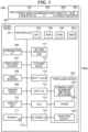
- FIG. 3 is a block diagram of the trailering system 1000.
- the marine vessel 100 includes the hull 100a (refer to FIGS. 1 and 2 ) and a propulsion device 120 provided on the hull 100a.
- the marine vessel 100 obtains a propulsive force by ejecting a jet by the propulsion device 120.
- the propulsion device 120 includes an engine 125 for generating a driving force, a forward-and-rearward switching mechanism 124 for transmitting the driving force of the engine 125 in an adjusted state, and an injection nozzle 126 for ejecting a jet.
- the propulsion device 120 includes a propeller (not illustrated) to which the driving force of the engine 125 is transmitted via the forward-and-rearward switching mechanism 124.
- the propulsion device 120 generates a jet from the injection nozzle 126 by rotating the propeller by the driving force.
- the propulsion device 120 adjusts the traveling direction of the marine vessel 100 by changing the ejection direction of the jet from the injection nozzle 126 generated by the rotation of the propeller.
- the marine vessel 100 further includes a controller 101, an engine control unit (ECU) 115, a shift control unit (CU) 114, and a steering CU 116.
- the controller 101 entirely controls the marine vessel 100 including the propulsion device 120.
- the controller 101 includes a CPU 102, a ROM 103, a RAM 104, and a timer 105.
- the ROM 103 stores a control program.
- the CPU 102 implements various types of control processing by loading the control program stored in the ROM 103 to the RAM 104 and executing the control program.
- the RAM 104 provides a work area when the CPU 102 executes the control program.
- the ECU 115, the shift CU 114, and the steering CU 116 control the engine 125, the forward-and-rearward switching mechanism 124, and the injection nozzle 126, respectively, based on an instruction from the controller 101.
- the marine vessel 100 further includes a sensor group 109.
- the sensor group 109 includes a tide sensor, a wind speed sensor, a wind direction sensor, an azimuth sensor, a steering angle sensor, a hook sensor, a water landing sensor, an acceleration sensor, a speed sensor, and an angular speed sensor (all not illustrated).
- the tide sensor detects a tide.
- the wind speed sensor detects a wind speed.
- the wind direction sensor detects a wind direction.
- the azimuth sensor detects an absolute azimuth of the hull 100a.
- the steering angle sensor detects a steering angle of hull 100a by detecting a rotation angle of a steering wheel 112.
- the hook sensor detects that the hook of the trailer 200 is hooked on the hull 100a.
- the water landing sensor detects that the injection nozzle 126 of the propulsion device 120 is located in the water.
- the acceleration sensor detects the posture of the hull 100a by detecting the inclination of the hull 100a in addition to detecting the acceleration of the hull 100a.
- the speed sensor detects the speed of the hull 100a, and the angular speed sensor detects the angular speed of the hull 100a. It is noted that it is not essential for the sensor group 109 to include all these sensors.
- the steering wheel 112 and a shift lever 113 are provided on the hull 100a of the marine vessel 100.
- the controller 101 controls the ejection direction of the jet ejected from the injection nozzle 126, via the steering CU 116, based on the rotation angle of the operated steering wheel 112.
- the controller 101 performs control to change a shift position in the forward-and-rearward switching mechanism 124, via the shift CU 114, based on the position of the operated shift lever 113.
- the marine vessel 100 further includes a memory 111, a display unit 110, a setting operation unit 117, a communication I/F 106, a wave signal receiver 107, and a GNSS receiver 108.
- the memory 111 is a nonvolatile storage medium.
- the display unit 110 includes a display, and displays various types of information based on an instruction from the controller 101.
- the display unit 110 may have a function of generating sound.
- the setting operation unit 117 includes an operator for performing an operation related to vessel steering, a setting operator for performing various settings, and an input operator for inputting various instructions (all not illustrated).
- the communication I/F 106 is capable of communicating with an external device in a wireless and/or wired manner.
- the GNSS receiver 108 periodically receives a global navigation satellite systems (GNSS) signal from a GNSS satellite.
- GNSS global navigation satellite systems
- a signal (described later) received by the wave signal receiver 107 and a signal received by the GNSS receiver 108 are supplied to the controller 101.
- the trailer 200 includes a wave signal generator 201, a communication I/F 202, an azimuth sensor 203, and a GNSS receiver 204.
- the communication I/F 202 is capable of communicating with an external device in a wireless and/or wired manner.
- the communication I/F 202 is further capable of communicating with the communication I/F 106 by near field communication or the like. It is noted that a communication method between the marine vessel 100 and the trailer 200 is not limited.
- the GNSS receiver 204 periodically receives a GNSS signal from a GNSS satellite.
- the azimuth sensor 203 detects an absolute azimuth of the trailer 200.
- the GNSS signal received by the GNSS receiver 204 is transmitted by the communication I/F 202 as a signal indicating a current position (an absolute position) of the trailer 200, and is received by the communication I/F 106 of the marine vessel 100.
- a signal indicating the azimuth (the absolute azimuth) of the trailer 200 detected by the azimuth sensor 203 is also transmitted by the communication I/F 202 and received by the communication I/F 106 of the marine vessel 100.
- the wave signal generator 201 and the wave signal receiver 107 will be described later.
- the controller 101 When executing predicted trajectory display processing (described later with reference to FIG. 6 ), the controller 101 specifies a trailer (hereinafter, referred to as a "target trailer") on which the hull 100a is to be loaded.
- a trailer hereinafter, referred to as a "target trailer"
- a known method may be adopted.
- the controller 101 acquires the current position of each trailer through wireless communication. Then, the controller 101 displays the acquired current positions of trailers on the screen of the display unit 110.
- the controller 101 specifies, on the display screen, the target trailer by receiving designation of a desired position among the positions of the respective trailers from a user.
- one of the trailers for which near field communication established may be specified as the target trailer.
- the controller 101 may receive information on the current position of the target trailer by wireless communication.
- the marine vessel 100 may receive a laser beam or a wave signal emitted from a certain trailer, whereby the certain trailer may be specified as the target trailer.
- the wave signal generator 201 provided in the trailer 200 emits a wave signal from at least three different positions whose "relative positional relationship" with each other is known.
- the wave signal is an optical signal
- the wave signal generator 201 is three LEDs
- the wave signal receiver 107 is a camera.
- the relative position information may be specified based on the wave signal emitted from each position and received by the wave signal receiver 107 provided in the marine vessel 100.
- the controller 101 can extract bright spots from an image obtained by the camera imaging the optical signals emitted from the three LEDs, and can acquire the relative position information (the trailer azimuth ⁇ , the vessel azimuth ⁇ , and the distance L) based on the positions of the bright spots in the image and the "relative positional relationship". It is noted that, in a case where a method that does not use a laser beam or a wave signal is adopted to specification of the target trailer, it is not essential to provide with the wave signal generator 201 and the wave signal receiver 107.
- the memory 111 stores characteristic information 111a to be described later.
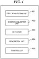
- FIG. 4 is a diagram illustrating a functional block for implementing the trailering support device.
- the functional block includes, as functional units, a first acquisition unit 401, a second acquisition unit 402, a detector 403, a generation unit 404, and a controller 405.
- Each of these functional units is mainly implemented through cooperation between at least one of: the communication I/F 106; the wave signal receiver 107; the GNSS receiver 108; the sensor group 109; the display unit 110; and the memory 111, and the controller 101.
- the function of the first acquisition unit 401 is mainly implemented by the controller 101.
- the first acquisition unit 401 reads and acquires the characteristic information 111a from the memory 111.
- the characteristic information 111a is determined in advance as information indicating a relationship between the steering angle of the hull 100a and the turning radius of the hull 100a.
- a manufacturer of the marine vessel 100 conducts an experiment using the hull 100a and measures the turning radius in a case where the steering angle is set to a certain value in a state where the vessel speed and the acceleration are kept constant, which is performed a plurality of times while changing the steering angle. Thereafter, the manufacturer obtains, by using interpolation processing or the like as necessary, a table or a function indicating the turning radius with respect to the steering angle, and stores the obtained table or function in the memory 111 as the characteristic information 111a.
- the function of the second acquisition unit 402 is mainly implemented by the controller 101, the communication I/F 106, the wave signal receiver 107, the GNSS receiver 108, and the sensor group 109.
- the second acquisition unit 402 acquires the above-described relative position information.
- the second acquisition unit 402 acquires the respective absolute positions of the hull 100a and the trailer 200 from the information received by the GNSS receiver 108 and the GNSS receiver 204, respectively.
- the second acquisition unit 402 may acquire the distance L, the vessel azimuth ⁇ , and the trailer azimuth ⁇ based on the wave signal received by the wave signal receiver 107.
- the function of the detector 403 is mainly implemented by the controller 101 and the sensor group 109.
- the detector 403 detects the steering angle by the steering angle sensor of the sensor group 109.
- the function of the generation unit 404 is mainly implemented by the controller 101.
- the generation unit 404 predicts a path of future movement of the hull 100a based on the characteristic information 111a acquired by the first acquisition unit 401, the relative position information acquired by the second acquisition unit 402, and the steering angle detected by the detector 403. Then, the generation unit 404 generates the predicted path of the future movement as a predicted trajectory 500.
- the predicted trajectory 500 will be described later in detail ( FIG. 5 ).
- the function of the controller 405 is mainly implemented by the controller 101 and the display unit 110.
- the controller 405 notifies of a positional relationship between the hull 100a and the trailer 200, and notifies of the predicted trajectory 500.
- the controller 405 displays, on the display screen of the display unit 110, an image showing the positional relationship between the hull 100a and the trailer 200, and displays the predicted trajectory 500 generated by the generation unit 404 in a state of being superimposed on the image.
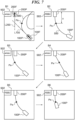
- FIG. 5 is a transition diagram of a predicted trajectory display screen.
- the predicted trajectory display screen is displayed on the display unit 110 by predicted trajectory display processing (to be described later with reference to FIG. 6 ) executed in parallel with manual trailering.
- screens A1 to A6 corresponding to the transition of the state of the hull 100a are illustrated as the predicted trajectory display screens.
- the screens A1 to A6 are displayed, after the start of the predicted trajectory display processing is instructed and the target trailer is specified.
- the respective current positions of the hull 100a and the trailer 200 are displayed on a screen in which the azimuth is defined, as an image in which the positional relationship between the hull 100a and the trailer 200 can be understood.
- a hull mark 100P indicating the position of the hull 100a and a trailer mark 200P indicating the position of the target trailer are displayed on the predicted trajectory display screen.
- the upper side of the display screen is set to the north, and the display position of the hull mark 100P is set as a reference (fixed).
- the display position of the hull mark 100P is set as the reference (fixed), and the relative position of the trailer 200 with respect to the hull 100a is indicated by the trailer mark 200P. Further, the predicted trajectory 500 starting from the hull mark 100P is displayed in a state of being superimposed on the image (the indications of the hull mark 100P and the trailer mark 200P displayed) in which the positional relationship between the hull 100a and the trailer 200 can be understood.
- the relative position information includes the trailer azimuth ⁇ and the vessel azimuth ⁇ if considering only to display the screen on which the positional relationship between the hull 100a and the trailer 200 can be understood, and it is sufficient that the relative position information includes at least the positional information of one of the hull 100a and the trailer 200 with respect to the other one of the hull 100a and the trailer 200 as the reference. Therefore, it is not essential to obtain both the position of the hull 100a and the position of the trailer 200. That is, for example, it is sufficient if the absolute position of the hull 100a, the direction in which the trailer 200 exists with respect to the hull 100a, and the distance from the hull 100a to the trailer 200 are known (are acquired).
- the controller 405 displays the hull mark 100P at a determined position on the screen.
- the controller 405 displays the trailer mark 200P at a relative position with respect to the hull mark 100P based on the relationship between the position of the trailer 200 and the position of the hull 100a indicated by the relative position information.
- the controller 405 displays the predicted trajectory 500 generated by the generation unit 404 superimposed on the indications of the hull mark 100P and the trailer mark 200P. In this manner, the predicted trajectory display screen is formed. Then, the transition of the predicted trajectory display screen will be described with reference to the screens A1 to A6 mentioned above.
- the screen A1 illustrates an initial state, which is a state immediately after the start of the predicted trajectory display processing. In this state, the predicted trajectory 500 significantly deviates from the trailer mark 200P.
- the screen A2 is displayed in a state where the vessel operator operates the steering wheel 112, and steers the hull 100a so that the hull 100a heads toward the trailer 200.
- the predicted trajectory 500 passes through the trailer mark 200P.
- a range to be displayed of the predicted trajectory 500 is not limited to a range from the hull mark 100P to the trailer mark 200P.
- a range of the predicted trajectory 500 after passing through the trailer mark 200P may be further displayed.
- the screen A3 is displayed in a state where the hull 100a has been navigated after the state in which the screen A2 is displayed. It is noted that the predicted trajectory 500 is generated over time, from time to time, and the display thereof is updated. The display position of the hull mark 100P is fixed, and therefore the position of the trailer mark 200P changes on the screen A3. As a result of the movement of the hull 100a, the predicted trajectory 500 deviates from the trailer mark 200P on the screen A3.
- the screen A4 is displayed in a state where the vessel operator operates the steering wheel 112 again in a state where the screen A3 is displayed, and steers the hull 100a so that the hull 100a heads toward the trailer 200. In this state, the predicted trajectory 500 passes through the trailer mark 200P again.
- the screen A5 is displayed in a state where the hull 100a has been navigated after the state in which the screen A4 is displayed. After the hull 100a has moved, a state in which the predicted trajectory 500 passes through the trailer mark 200P is maintained, on the screen A5.
- the screen A6 is displayed in a state where the hull 100a has been navigated after the state in which the screen A5 is displayed.
- a state in which the predicted trajectory 500 passes through the trailer mark 200P is maintained, and at this time, the marine vessel 100 is in a state immediately before being loaded onto the trailer 200. Normally, when this vessel steering state is continued, loading of the marine vessel 100 onto the trailer 200 is implemented.
- FIG. 6 is a flowchart illustrating the predicted trajectory display processing. This processing is started in response to an instruction to start the predicted trajectory display processing. This processing is implemented by the CPU 102 loading the control program stored in the ROM 103 in the RAM 104 and executing the control program. The predicted trajectory display processing will be described also with reference to FIG. 5 .
- step S101 the CPU 102 reads and acquires the characteristic information 111a from the memory 111.
- step S102 the CPU 102 specifies, by the above-described method, a target trailer onto which the hull 100a is to be loaded.
- step S103 the CPU 102 executes other processing.
- the CPU 102 can execute, for example, processing for ending the predicted trajectory display processing illustrated in FIG. 6 , and the like, in response to an instruction from a user.
- step S104 the CPU 102 acquires relative position information.
- step S105 the CPU 102 acquires a current vessel steering state.
- the CPU 102 acquires a steering angle and a speed of the hull 100a from the detection result by the sensor group 109.
- step S106 the CPU 102 determines whether or not a "manual trailering condition" is satisfied.
- the manual trailering condition is that both the speed of the hull 100a and the distance L satisfy a predetermined condition. Therefore, in a case where at least one of the speed of the hull 100a and the distance L does not satisfy the predetermined condition, the manual trailering condition is not satisfied.
- the manual trailering condition is satisfied when the speed of the hull 100a is less than a predetermined speed and the distance L indicated by the relative position information is less than a first predetermined distance.
- the predetermined speed is set to a value of a low speed corresponding to a speed of the hull 100a in idle state, the hull 100a held at a fixed point, or the like.
- the first predetermined distance is set to a value (for example, 50 m) that allows visual recognition of the trailer 200 from the hull 100a. This is because the manual trailering can be appropriately performed when the hull 100a is at a low speed and the trailer 200 is in a viewing range.
- the predicted trajectory 500 is estimated in a state where the manual trailering condition is not satisfied, the estimation accuracy of the predicted trajectory 500 deteriorates.
- step S106 in a case where it is determined that the manual trailering condition is not satisfied, the CPU 102 returns the processing to step S103, whereas in a case where it is determined that the manual trailering condition is satisfied, the CPU 102 advances the processing to step S107. It is noted that it is not essential to provide step S106.
- step S107 the CPU 102 executes estimation processing.
- the CPU 102 generates the predicted trajectory 500 based on the characteristic information 111a acquired in step S101, the relative position information acquired in step S104, and the steering angle acquired in step S105.
- the CPU 102 obtains the turning radius corresponding to the steering angle from the characteristic information 111a.
- the CPU 102 generates, based on the obtained turning radius, the predicted trajectory 500 with the position of the hull 100a indicated by the relative position information as a starting point.
- step S108 the CPU 102 executes display processing of displaying the predicted trajectory display screen illustrated in FIG. 5 on the display unit 110.
- the CPU 102 displays, on the screen, an image including the hull mark 100P indicating the position of the hull 100a in the relative position information and the trailer mark 200P indicating the position of the target trailer in the relative position information, and further displays the predicted trajectory 500 in a state of being superimposed on this image (for example, the screen A1).
- the vessel operator can visually recognize the predicted trajectory 500 on the image in which the positional relationship between the hull 100a and the trailer 200 is known, and thus the vessel operator can appropriately determine how he/she should steer the vessel thereafter.
- step S109 the CPU 102 determines whether or not it is in a situation that at least one of: the fact that the hull 100a has moved by a second predetermined distance after the last generation of the predicted trajectory 500; and the fact that a predetermined period of time has elapsed after the last generation of the predicted trajectory 500.
- the last predicted trajectory 500 is generated in the immediately preceding step S107. It is noted that, in step S107, clocking for determining the elapse of the predetermined period of time is started. The CPU 102 continues determination in step S109 until the hull 100a moves by the second predetermined distance or the predetermined period of time elapses, after the last generation of the predicted trajectory 500.
- step S109 the CPU 102 returns to step S103 in a case where at least one of: the fact that the hull 100a has moved by the second predetermined distance after the last generation of the predicted trajectory 500; and the fact that the predetermined period of time has elapsed after the last generation of the predicted trajectory 500, is satisfied. Therefore, by the next processing of steps S103 to S108, the new predicted trajectory 500 is generated based on the characteristic information 111a acquired in step S101, the newly acquired relative position information, and the newly detected steering angle, to the predicted trajectory display screen is updated (for example, the screen A2 ⁇ the screen A3).
- the predicted trajectory display screen is updated every time the hull 100a moves by the second predetermined distance or every time the predetermined period of time elapses. It is noted that, in step S109, the determination may be made using only one of the the traveling distance of the hull 100a after the last generation of the predicted trajectory 500 and the elapsed time after the last generation of the predicted trajectory 500. It is noted that it is not essential to provide step S109, and the processing may proceed to step S103 after step S108.
- the predicted trajectory 500 is generated based on the characteristic information 111a indicating the relationship between the steering angle of the hull 100a and the turning radius of the hull 100a, the relative position information between the trailer 200 and the hull 100a, and the detected steering angle.
- the display screen On the display screen, an image indicating the positional relationship between the hull 100a and the trailer 200 and the predicted trajectory 500 are superimposed and displayed.
- the vessel operator can grasp how the hull 100a moves at the current steering angle or how to correct steering in order to suitably load the marine vessel 100 onto the trailer 200, by visually recognizing the predicted trajectory 500 while visually recognizing the relative position between the hull 100a and the trailer 200.
- the display of the predicted trajectory 500 changes in conjunction therewith, which allows even a beginner to feel a correspondence between the steering and the predicted trajectory 500.
- the trailering operation of the vessel operator can be supported.
- the predicted trajectory display screen is updated every time the vessel moves by the second predetermined distance and/or every time the predetermined period of time elapses, which allows the vessel operator to visually recognize the latest positional relationship between the hull 100a and the trailer 200 and the latest predicted trajectory 500.
- the predicted trajectory 500 is not generated (NO in S106). Therefore, it is possible to avoid generation and display of the predicted trajectory 500 with low accuracy.
- the characteristic information 111a may include information (for example, a time constant ⁇ ) indicating a speed at which the turning radius changes from a current value to a steady value according to the steering angle.
- the time constant ⁇ is, for example, a period of time required for the turning radius to become 63% or about 63% of the steady value.
- the estimation processing (S107) the turning radius corresponding to the steering angle is obtained from the characteristic information 111a, and the predicted trajectory 500 is generated based on the turning radius and the time constant ⁇ . As a result, the predicted trajectory 500 can be obtained with higher accuracy.
- the characteristic information 111a may include information indicating the turning radius with respect to a "combination of at least one parameter of: the output of the propulsion device 120; the speed of the hull 100a; and the acceleration of the hull 100a, and the steering angle".
- step S105 not only the steering angle but also the above-mentioned at least one parameter is acquired.
- the predicted trajectory 500 is generated based on the turning radius corresponding to the combination of the at least one parameter and the steering angle. As a result, the predicted trajectory 500 corresponding to the behavior of the hull 100a can be generated.
- the CPU 102 may acquire, in step S105, disturbance information (for example, at least one of the wind speed, the wind direction, and the tide) by detection. Then, in the estimation processing (S107), the CPU 102 may generate the predicted trajectory 500 based on the characteristic information 111a, the relative position information, the detected steering angle, and the detected disturbance information. As a result, the more accurate predicted trajectory 500 can be obtained in consideration of disturbance.
- disturbance information for example, at least one of the wind speed, the wind direction, and the tide
- the disturbance information (for example, at least one of the wind speed, the wind direction, and the tide) may be acquired in step S105, and the fact that the disturbance is in a predetermined state may be added to a satisfaction requirement of the manual trailering condition in step S106.
- a second preferred embodiment of the present invention in the predicted trajectory display processing, it is determined whether or not the hull 100a can be loaded onto the trailer 200, and further, the relative relationship between the direction of the hull 100a and the direction of the trailer 200 is displayed so as to be understood.
- Other points not specifically mentioned are similar to those of the first preferred embodiment. It is noted that only one of determining whether or not the hull 100a can be loaded onto the trailer 200 and displaying the relationship of the direction of the directions of the hull 100a and the trailer 200 relative to each other may be adopted.
- FIG. 7 is a transition diagram of a predicted trajectory display screen according to the second preferred embodiment.
- This predicted trajectory display screen is displayed on the display unit 110 by predicted trajectory display processing (to be described later with reference to FIG. 8 ) executed in parallel with the manual trailering.
- screens B1 to B6 corresponding to the transition of the state of the hull 100a are illustrated as the predicted trajectory display screens.
- the screens B1 to B6 are displayed, after the start of the predicted trajectory display processing is instructed and the target trailer is specified.
- the hull mark 100P and the trailer mark 200P are displayed on the predicted trajectory display screen. Further, the predicted trajectory 500 starting from the hull mark 100P is displayed in a superimposed manner on the indications of the hull mark 100P and the trailer mark 200P.
- the display position of the trailer mark 200P is used as a reference (fixed), and the relative position of the hull 100a with respect to the trailer 200 is indicated by the hull mark 100P.
- an arrow-shaped mark 100F indicating the direction of the hull 100a is added to the hull mark 100P, and an extension line L100 of the center line of the mark 100F is further displayed.
- An arrow-shaped mark 200F indicating the direction of the trailer 200 is added to the trailer mark 200P, and an extension line L200 of the center line of the mark 200F is displayed. It is noted that, in FIG. 7 , the marks 100F and 200F and the extension lines L100 and L200, which can actually be displayed in the screens B2 to B6, are omitted.
- a relative relationship between the direction of the hull 100a and the direction of the trailer 200 is understood by the mark 100F and the mark 200F.
- the extension line L100 and the extension line L200 are parallel to each other, it can be understood that the directions of the hull 100a and the trailer 200 coincide with each other.
- the extension line L100 and the extension line L200 almost coincide with each other at the time when the hull 100a comes close to the trailer 200, it can be understood that the feasibility of loading the marine vessel 100 onto the trailer 200 is high.
- a display area 502 "possible” indicating that the marine vessel 100 can be loaded onto the trailer 200 (“loadable”) or “impossible” indicating that the marine vessel 100 cannot be loaded onto the trailer 200 (“unloadable”) is displayed.
- loadable the marine vessel 100 can be loaded onto the trailer 200
- impossible the marine vessel 100 cannot be loaded onto the trailer 200
- unloadable the vessel operator is able to grasp whether the the marine vessel 100 can be loaded onto the trailer 200 when vessel steering is continuously performed as it is.
- a predetermined position Px is a position at which the trailer 200 and the hull 100a have a predetermined positional relationship on the predicted trajectory 500.
- the predetermined position Px is a position at which the distance L between the reference position PT of the trailer 200 and the reference position PB of the marine vessel 100 (refer to FIG. 2 ) in the longitudinal direction of the trailer 200 becomes a third predetermined distance D (exemplified in the screen B2).
- the third predetermined distance D is predetermined 0 or a value lager than 0. It is not essential to display a mark indicating the predetermined position Px or an indication of the third predetermined distance D on the screen.
- the "allowable range” mentioned herein is, for example, a range in which both the trailer azimuth ⁇ and the vessel azimuth ⁇ are within ⁇ 30 degrees (a range of -30 degrees or more and +30 degrees or less).
- the screen B1 illustrates an initial state, which is a state immediately after the start of the predicted trajectory display processing.
- the predicted trajectory 500 significantly deviates from the trailer mark 200P.
- the predicted trajectory 500 does not pass through the trailer 200, and hence "impossible” is displayed in the display area 502 in the screen B1.
- the screen B2 is displayed in a state where the vessel operator operates the steering wheel 112, and steers the hull 100a so that the hull 100a heads toward the trailer 200.
- the predicted trajectory 500 passes through the trailer mark 200P.
- both the estimated trailer azimuth ⁇ and the estimated vessel azimuth ⁇ at the predetermined position Px are within the allowable range. Therefore, "possible" is displayed in the display area 502 in the screen B2.
- the screen B3 is displayed in a state where the hull 100a has been navigated after a state in which the screen B2 is displayed.
- the predicted trajectory 500 deviates from the trailer mark 200P in the screen B3. Therefore, "impossible” is displayed in the display area 502 in the screen B3.
- the screen B4 is displayed in a state where the vessel operator operates the steering wheel 112 again in a state where the screen B3 is displayed, and steers the hull 100a so that the hull 100a heads toward the trailer 200.
- the predicted trajectory 500 passes through the trailer mark 200P again.
- the predicted trajectory 500 is substantially straight, and at least one of the estimated trailer azimuth ⁇ and the estimated vessel azimuth ⁇ at the predetermined position Px exceeds ⁇ 30 degrees (out of the allowable range). Therefore, "impossible" is displayed in the display area 502 in the screen B4.
- the screen B5 is displayed in a state in which the vessel operator operates the steering wheel 112 again in a state where the screen B4 is displayed, to correct the azimuth and the steering such that the shape of the predicted trajectory 500 becomes curved.
- the predicted trajectory 500 passes through the trailer mark 200P again.
- the predicted trajectory 500 passes through the trailer 200, and the estimated trailer azimuth ⁇ and the estimated vessel azimuth ⁇ at the predetermined position Px are both within ⁇ 30 degrees (within the allowable range). Therefore, "possible" is displayed in the display area 502 in the screen B5.
- the screen B6 is displayed in a state where, after the screen B5 is displayed, the hull 100a moves along the predicted trajectory 500 and is located at the predetermined position Px, and the hull 100a (the marine vessel 100) is just before being loaded onto the trailer 200.
- "possible” is still displayed in the display area 502. Normally, when this vessel steering state is continued, the loading of the marine vessel 100 onto the trailer 200 is implemented.
- FIG. 8 is a flowchart illustrating the predicted trajectory display processing according to the second preferred embodiment.
- a start condition and an execution subject of this processing are similar to those of the predicted trajectory display processing ( FIG. 6 ) according to the first preferred embodiment.
- the predicted trajectory display processing ( FIG. 8 ) according to the second preferred embodiment is different from the flowchart of the predicted trajectory display processing ( FIG. 6 ) according to the first preferred embodiment in that steps S201 to S203 are added between steps S107 and S108. Furthermore, a part of the processing in steps S107 and S108 of the second preferred embodiment is different from that of the first preferred embodiment.
- the processing of steps S101 to S106 is similar to that of the first preferred embodiment.
- the relative position information acquired in step S104 includes the current trailer azimuth ⁇ and the current vessel azimuth ⁇ .
- the CPU 102 In the estimation processing in step S107, the CPU 102 generates the predicted trajectory 500 as in the first preferred embodiment. Further, the CPU 102 estimates the trailer azimuth ⁇ and the vessel azimuth ⁇ at the predetermined position Px from a tangential direction of the predicted trajectory 500 at the predetermined position Px, a predicted position of the hull 100a, and an absolute azimuth of the trailer 200.
- step S201 it is determined whether or not the hull 100a can be loaded onto the trailer 200.
- the CPU 102 determines that the loading cannot be performed (NO in step S201).
- the CPU 102 determines that the loading cannot be performed (NO in step S201).
- the CPU 102 determines that the loading can be performed (YES in step S201).
- the CPU 102 displays "possible" in the display area 502 in step S202, thereby notifying of that the loading can be performed.
- the vessel operator is able to understand that the current trailering operation is appropriately performed.
- the CPU 102 displays "impossible" in the display area 502 in step S203, thereby notifying of that the loading cannot be performed.
- the vessel operator is able to understand that the trailering operation should be corrected.
- step S108 the processing proceeds to step S108.
- the CPU 102 displays the hull mark 100P and the trailer mark 200P on the screen.
- the CPU 102 also displays the marks 100F and 200F and the extension lines L100 and L200 on the screen so that the relative relationship between the direction of the hull 100a and the direction of the trailer 200 can be understood. Further, the CPU 102 displays the predicted trajectory 500 on this screen in a superimposed manner.
- step S109 The processing in step S109 of the second preferred embodiment is similar to that of the first preferred embodiment.
- the marks 100F and 200F and the extension lines L100 and L200 are displayed on the predicted trajectory display screen so that the relative relationship between the direction of the hull 100a and the direction of the trailer 200 can be understood, which makes it possible for the vessel operator to more easily determine whether or not the current operation state is appropriate.
- the display position of the hull mark 100P is used as the reference (fixed) in the first preferred embodiment ( FIG. 5 ), and the display position of the trailer mark 200P is used as the reference (fixed) in the second preferred embodiment ( FIG. 7 ).
- the first preferred embodiment and the second preferred embodiment it does not matter which display position of the hull mark 100P or the trailer mark 200P is fixed as a reference.
- the predicted trajectory display screen ( FIG. 7 ) may be displayed with an azimuth such as the north being fixed.
- the indication of "possible”, the indication of "impossible”, the hull mark 100P, the trailer mark 200P, the predicted trajectory 500, the marks 100F and 200F, the extension lines L100 and L200, and the like are examples of display modes, and display modes are not limited thereto.
- display modes are not limited thereto.
- whether or the hull 100a can be loaded onto the trailer 200 may be notified by displaying a message or the like, instead of displaying "possible” and “impossible”. Instead of these displays or in addition to these displays, whether the hull 100a can be loaded onto the trailer 200 may be notified by voice.
- the method of notifying of the positional relationship between the hull 100a and the trailer 200, of the relative relationship between the direction of the hull 100a and the direction of the trailer 200, and of the predicted trajectory 500 is not limited to the screen display.
- notification may be performed by voice.
- voice for example, by issuing a voice message notifying of the relative azimuth and distance of the trailer 200 with respect to the hull 100a, the positional relationship between them or the relative relationship between the directions of them may be notified.
- a voice message may be issued to notify of whether or not the predicted trajectory 500 is passing through the trailer 200 and/or of whether or not the predicted trajectory 500 deviates from the trailer 200.
- the direction of the deviation left or right with respect to the trailer 200
- the amount of deviation may also be notified by a voice message.
- a trailering support device configured to perform trailering for loading a hull onto a trailer
- the trailering support device comprising one or more controllers configured to function as: a first acquisition unit configured to acquire characteristic information predetermined as information indicating a relationship between a steering angle of the hull and a turning radius of the hull; a second acquisition unit configured to acquire relative position information between the trailer and the hull; a detector configured to detect the steering angle of the hull; a generation unit configured to predict future movement of the hull based on the characteristic information acquired by the first acquisition unit, the relative position information acquired by the second acquisition unit, and the steering angle detected by the detector, and to generate a predicted trajectory; and a controlling unit configured to notify of a positional relationship between the hull and the trailer and to notify of the predicted trajectory generated by the generation unit.
- the relative position information includes position information of one of the hull and the trailer with reference to the other of the hull and the trailer as a reference.
- the relative position information further includes a first azimuth which is an azimuth of the trailer as viewed from the hull and a second azimuth which is an azimuth of the hull as viewed from the trailer.
- the controlling unit is further configured to: estimate the first azimuth and the second azimuth at a position where the trailer and the hull form a predetermined positional relationship on the predicted trajectory; and in a case where at least one of the estimated first azimuth and the estimated second azimuth exceeds an allowable range, notify that the loading of the hull onto the trailer is not performable.
- the controlling unit notifies of that the loading of the hull onto the trailer is performable, in a case where the predicted trajectory passes through the trailer and neither the estimated first azimuth nor the estimated second azimuth exceeds the allowable range.
- the allowable range is a range of -30 degrees or more and +30 degrees or less.
- the present invention can also be realized by processing in which a program for implementing one or more functions of the above-described preferred embodiments is supplied to a system or a device via a network or a non-transitory storage medium, and one or more processors of a computer of the system or the device reads and executes the program.
- the above program and the storage medium storing the above program constitute the present invention.
- the present invention can also be implemented by a circuit (for example, ASIC) that implements one or more functions.
- the present invention is not limited to being applied to the jet boat, and can also be applied to various marine vessels propelled by an outboard motor, an inboard motor, or an inboard/outboard motor.
Landscapes
- Engineering & Computer Science (AREA)
- Mechanical Engineering (AREA)
- Ocean & Marine Engineering (AREA)
- Chemical & Material Sciences (AREA)
- Combustion & Propulsion (AREA)
- Radar, Positioning & Navigation (AREA)
- Transportation (AREA)
- Public Health (AREA)
- Health & Medical Sciences (AREA)
- Remote Sensing (AREA)
- Computer Vision & Pattern Recognition (AREA)
- Physics & Mathematics (AREA)
- General Physics & Mathematics (AREA)
- Theoretical Computer Science (AREA)
- Traffic Control Systems (AREA)
- Control Of Position, Course, Altitude, Or Attitude Of Moving Bodies (AREA)
Abstract
Description
- The present invention relates to a trailering support device and method, and a marine vessel including the trailering support device.
- Conventionally, a trailering in which a hull is loaded onto a trailer has been performed mainly to land a small hull. International Publication
WO 2016/163559 discloses a technique for acquiring positions of a hull and a trailer and controlling a propulsion device or the like to automatically load (mount) the hull onto the trailer. Meanwhile, there is a case in which it is desired to manually perform trailering. - However, the way the hull behaves in response to an operation such as steering varies depending on the specifications of the hull. Therefore, it is not easy for an inexperienced vessel operator to accurately predict how the hull turns when the hull is steered at a certain angle. Therefore, manual trailering is not always easy.
- The present invention provides a trailering support device and a method capable of supporting a trailering operation, and a marine vessel including the trailering support device.
- According to a preferred embodiment of the present invention, a trailering support device configured to perform trailering for loading a hull onto a trailer, the trailering support device comprising one or more controllers configured to function as: a first acquisition unit configured to acquire characteristic information predetermined as information indicating a relationship between a steering angle of the hull and a turning radius of the hull; a second acquisition unit configured to acquire relative position information between the trailer and the hull; a detector configured to detect the steering angle of the hull; a generation unit configured to predict future movement of the hull based on the characteristic information acquired by the first acquisition unit, the relative position information acquired by the second acquisition unit, and the steering angle detected by the detector, and to generate a predicted trajectory; and a controlling unit configured to notify of a positional relationship between the hull and the trailer and to notify of the predicted trajectory generated by the generation unit.
- According to this configuration, characteristic information indicating a relationship between a steering angle of a hull and a turning radius of the hull is acquired, relative position information between a trailer and the hull is acquired, and the steering angle of the hull is detected. The future movement of the hull is predicted based on the acquired characteristic information, the acquired relative position information, and the detected steering angle, and a predicted trajectory is generated. A positional relationship between the hull and the trailer is notified, and the generated predicted trajectory is notified.
- The above and other elements, features, steps, characteristics and advantages of the present invention will become more apparent from the following detailed description of the preferred embodiments with reference to the attached drawings.
-
-
FIG. 1 is a side view illustrating an example of a trailering system to which a trailering support device is applied. -
FIG. 2 is a top view illustrating an example of the trailering system. -
FIG. 3 is a block diagram of the trailering system. -
FIG. 4 is a diagram illustrating a functional block for implementing the trailering support device. -
FIG. 5 is a transition diagram of a predicted trajectory display screen. -
FIG. 6 is a flowchart illustrating predicted trajectory display processing. -
FIG. 7 is a transition diagram of a predicted trajectory display screen according to a second preferred embodiment. -
FIG. 8 is a flowchart illustrating predicted trajectory display processing according to the second preferred embodiment. - Hereinafter, preferred embodiments of the present invention will be described with reference to the drawings.
-
FIG. 1 is a side view illustrating an example of atrailering system 1000 to which a trailering support device according to a first preferred embodiment of the present invention is applied.FIG. 2 is a top view illustrating an example of thetrailering system 1000. Thetrailering system 1000 includes amarine vessel 100 and atrailer 200 on which themarine vessel 100 can be placed. Thetrailer 200 is a trailer for a marine vessel towed by avehicle 99 operated by a driver. Themarine vessel 100 is, for example, a so-called jet boat. - The
trailering system 1000 is a system capable of detaching themarine vessel 100 from thetrailer 200 and attaching the marine vessel to thetrailer 200. An inclined portion (ramp) R inclined downwards toward the bottom of water is formed on the waterside. When moving themarine vessel 100 from thetrailer 200 on aland 97 to a water surface 98 (when themarine vessel 100 leaves the trailer 200), a driver drives thevehicle 99 to move thetrailer 200 to the inclined portion R, as illustrated inFIG. 1 . Then, a vessel operator of themarine vessel 100 moves themarine vessel 100 in a direction away from thetrailer 200. - When moving the
marine vessel 100 from thewater surface 98 to thetrailer 200 on the land 97 (when themarine vessel 100 is attached to the trailer 200), the driver first moves thetrailer 200 to the inclined portion R. Then, the vessel operator of themarine vessel 100 manually steers themarine vessel 100 to move themarine vessel 100 to the inclined portion R, and then loads themarine vessel 100 onto thetrailer 200. - Here, "relative position information" between the
marine vessel 100 and thetrailer 200 will be described. Reference positions in defining the relative position information include a reference position PT in thetrailer 200 and a reference position PB in themarine vessel 100, as illustrated inFIG. 2 . The reference position PT and the reference position PB may be respectively any portion of thetrailer 200 and themarine vessel 100. The "relative position information" includes to an absolute position of ahull 100a and an absolute position of thetrailer 200, and may include a distance L, a vessel azimuth ϕ (a second azimuth), and a trailer azimuth θ (a first azimuth). The distance L, the vessel azimuth ϕ, and the trailer azimuth θ are defined as quantities as viewed from above as illustrated inFIG. 2 . The distance L may be defined from the absolute position of thehull 100a and the absolute position of thetrailer 200. - The distance L is a distance between the
trailer 200 and themarine vessel 100. That is, the distance L is a linear distance between the reference position PT and the reference position PB. The vessel azimuth ϕ is a relative azimuth (direction) of themarine vessel 100 as viewed from thetrailer 200. The trailer azimuth θ is a relative azimuth (direction) of thetrailer 200 as viewed from themarine vessel 100. -
FIG. 3 is a block diagram of thetrailering system 1000. Themarine vessel 100 includes thehull 100a (refer toFIGS. 1 and2 ) and apropulsion device 120 provided on thehull 100a. Themarine vessel 100 obtains a propulsive force by ejecting a jet by thepropulsion device 120. - The
propulsion device 120 includes anengine 125 for generating a driving force, a forward-and-rearward switching mechanism 124 for transmitting the driving force of theengine 125 in an adjusted state, and aninjection nozzle 126 for ejecting a jet. Thepropulsion device 120 includes a propeller (not illustrated) to which the driving force of theengine 125 is transmitted via the forward-and-rearward switching mechanism 124. Thepropulsion device 120 generates a jet from theinjection nozzle 126 by rotating the propeller by the driving force. In addition, thepropulsion device 120 adjusts the traveling direction of themarine vessel 100 by changing the ejection direction of the jet from theinjection nozzle 126 generated by the rotation of the propeller. - The
marine vessel 100 further includes acontroller 101, an engine control unit (ECU) 115, a shift control unit (CU) 114, and asteering CU 116. Thecontroller 101 entirely controls themarine vessel 100 including thepropulsion device 120. Thecontroller 101 includes aCPU 102, aROM 103, aRAM 104, and atimer 105. TheROM 103 stores a control program. TheCPU 102 implements various types of control processing by loading the control program stored in theROM 103 to theRAM 104 and executing the control program. TheRAM 104 provides a work area when theCPU 102 executes the control program. - The
ECU 115, theshift CU 114, and thesteering CU 116 control theengine 125, the forward-and-rearward switching mechanism 124, and theinjection nozzle 126, respectively, based on an instruction from thecontroller 101. - The
marine vessel 100 further includes asensor group 109. Thesensor group 109 includes a tide sensor, a wind speed sensor, a wind direction sensor, an azimuth sensor, a steering angle sensor, a hook sensor, a water landing sensor, an acceleration sensor, a speed sensor, and an angular speed sensor (all not illustrated). The tide sensor detects a tide. The wind speed sensor detects a wind speed. The wind direction sensor detects a wind direction. The azimuth sensor detects an absolute azimuth of thehull 100a. The steering angle sensor detects a steering angle ofhull 100a by detecting a rotation angle of asteering wheel 112. - The hook sensor detects that the hook of the
trailer 200 is hooked on thehull 100a. The water landing sensor detects that theinjection nozzle 126 of thepropulsion device 120 is located in the water. The acceleration sensor detects the posture of thehull 100a by detecting the inclination of thehull 100a in addition to detecting the acceleration of thehull 100a. The speed sensor detects the speed of thehull 100a, and the angular speed sensor detects the angular speed of thehull 100a. It is noted that it is not essential for thesensor group 109 to include all these sensors. - The
steering wheel 112 and ashift lever 113 are provided on thehull 100a of themarine vessel 100. Thecontroller 101 controls the ejection direction of the jet ejected from theinjection nozzle 126, via thesteering CU 116, based on the rotation angle of the operatedsteering wheel 112. In addition, thecontroller 101 performs control to change a shift position in the forward-and-rearward switching mechanism 124, via theshift CU 114, based on the position of the operatedshift lever 113. - The
marine vessel 100 further includes amemory 111, adisplay unit 110, asetting operation unit 117, a communication I/F 106, awave signal receiver 107, and aGNSS receiver 108. Thememory 111 is a nonvolatile storage medium. Thedisplay unit 110 includes a display, and displays various types of information based on an instruction from thecontroller 101. Thedisplay unit 110 may have a function of generating sound. The settingoperation unit 117 includes an operator for performing an operation related to vessel steering, a setting operator for performing various settings, and an input operator for inputting various instructions (all not illustrated). - The communication I/
F 106 is capable of communicating with an external device in a wireless and/or wired manner. TheGNSS receiver 108 periodically receives a global navigation satellite systems (GNSS) signal from a GNSS satellite. A signal (described later) received by thewave signal receiver 107 and a signal received by theGNSS receiver 108 are supplied to thecontroller 101. - The
trailer 200 includes awave signal generator 201, a communication I/F 202, anazimuth sensor 203, and aGNSS receiver 204. The communication I/F 202 is capable of communicating with an external device in a wireless and/or wired manner. The communication I/F 202 is further capable of communicating with the communication I/F 106 by near field communication or the like. It is noted that a communication method between themarine vessel 100 and thetrailer 200 is not limited. TheGNSS receiver 204 periodically receives a GNSS signal from a GNSS satellite. Theazimuth sensor 203 detects an absolute azimuth of thetrailer 200. - The GNSS signal received by the
GNSS receiver 204 is transmitted by the communication I/F 202 as a signal indicating a current position (an absolute position) of thetrailer 200, and is received by the communication I/F 106 of themarine vessel 100. In addition, a signal indicating the azimuth (the absolute azimuth) of thetrailer 200 detected by theazimuth sensor 203 is also transmitted by the communication I/F 202 and received by the communication I/F 106 of themarine vessel 100. Thewave signal generator 201 and thewave signal receiver 107 will be described later. - When executing predicted trajectory display processing (described later with reference to
FIG. 6 ), thecontroller 101 specifies a trailer (hereinafter, referred to as a "target trailer") on which thehull 100a is to be loaded. As a method for specifying the target trailer, a known method may be adopted. As an example of this method, for example, in a case where there are a plurality of trailers that transmit position information, thecontroller 101 acquires the current position of each trailer through wireless communication. Then, thecontroller 101 displays the acquired current positions of trailers on the screen of thedisplay unit 110. Thecontroller 101 specifies, on the display screen, the target trailer by receiving designation of a desired position among the positions of the respective trailers from a user. - Alternatively, one of the trailers for which near field communication established may be specified as the target trailer. In this case, the
controller 101 may receive information on the current position of the target trailer by wireless communication. - Alternatively, a method disclosed in
Japanese Patent Application No. 2021-122618 Japanese Patent Application No. 2021-116970 marine vessel 100 may receive a laser beam or a wave signal emitted from a certain trailer, whereby the certain trailer may be specified as the target trailer. For example, thewave signal generator 201 provided in thetrailer 200 emits a wave signal from at least three different positions whose "relative positional relationship" with each other is known. As an example, the wave signal is an optical signal, thewave signal generator 201 is three LEDs, and thewave signal receiver 107 is a camera. - The relative position information may be specified based on the wave signal emitted from each position and received by the
wave signal receiver 107 provided in themarine vessel 100. For example, thecontroller 101 can extract bright spots from an image obtained by the camera imaging the optical signals emitted from the three LEDs, and can acquire the relative position information (the trailer azimuth θ, the vessel azimuth ϕ, and the distance L) based on the positions of the bright spots in the image and the "relative positional relationship". It is noted that, in a case where a method that does not use a laser beam or a wave signal is adopted to specification of the target trailer, it is not essential to provide with thewave signal generator 201 and thewave signal receiver 107. - The
memory 111 storescharacteristic information 111a to be described later. -
FIG. 4 is a diagram illustrating a functional block for implementing the trailering support device. The functional block includes, as functional units, afirst acquisition unit 401, asecond acquisition unit 402, adetector 403, ageneration unit 404, and acontroller 405. - Each of these functional units is mainly implemented through cooperation between at least one of: the communication I/
F 106; thewave signal receiver 107; theGNSS receiver 108; thesensor group 109; thedisplay unit 110; and thememory 111, and thecontroller 101. - The function of the
first acquisition unit 401 is mainly implemented by thecontroller 101. Thefirst acquisition unit 401 reads and acquires thecharacteristic information 111a from thememory 111. Thecharacteristic information 111a is determined in advance as information indicating a relationship between the steering angle of thehull 100a and the turning radius of thehull 100a. For example, a manufacturer of themarine vessel 100 conducts an experiment using thehull 100a and measures the turning radius in a case where the steering angle is set to a certain value in a state where the vessel speed and the acceleration are kept constant, which is performed a plurality of times while changing the steering angle. Thereafter, the manufacturer obtains, by using interpolation processing or the like as necessary, a table or a function indicating the turning radius with respect to the steering angle, and stores the obtained table or function in thememory 111 as thecharacteristic information 111a. - The function of the
second acquisition unit 402 is mainly implemented by thecontroller 101, the communication I/F 106, thewave signal receiver 107, theGNSS receiver 108, and thesensor group 109. Thesecond acquisition unit 402 acquires the above-described relative position information. For example, thesecond acquisition unit 402 acquires the respective absolute positions of thehull 100a and thetrailer 200 from the information received by theGNSS receiver 108 and theGNSS receiver 204, respectively. In addition, thesecond acquisition unit 402 may acquire the distance L, the vessel azimuth ϕ, and the trailer azimuth θ based on the wave signal received by thewave signal receiver 107. - The function of the
detector 403 is mainly implemented by thecontroller 101 and thesensor group 109. Thedetector 403 detects the steering angle by the steering angle sensor of thesensor group 109. - The function of the
generation unit 404 is mainly implemented by thecontroller 101. Thegeneration unit 404 predicts a path of future movement of thehull 100a based on thecharacteristic information 111a acquired by thefirst acquisition unit 401, the relative position information acquired by thesecond acquisition unit 402, and the steering angle detected by thedetector 403. Then, thegeneration unit 404 generates the predicted path of the future movement as a predictedtrajectory 500. The predictedtrajectory 500 will be described later in detail (FIG. 5 ). - The function of the
controller 405 is mainly implemented by thecontroller 101 and thedisplay unit 110. Thecontroller 405 notifies of a positional relationship between thehull 100a and thetrailer 200, and notifies of the predictedtrajectory 500. For example, thecontroller 405 displays, on the display screen of thedisplay unit 110, an image showing the positional relationship between thehull 100a and thetrailer 200, and displays the predictedtrajectory 500 generated by thegeneration unit 404 in a state of being superimposed on the image. -
FIG. 5 is a transition diagram of a predicted trajectory display screen. The predicted trajectory display screen is displayed on thedisplay unit 110 by predicted trajectory display processing (to be described later with reference toFIG. 6 ) executed in parallel with manual trailering. InFIG. 5 , screens A1 to A6 corresponding to the transition of the state of thehull 100a are illustrated as the predicted trajectory display screens. The screens A1 to A6 are displayed, after the start of the predicted trajectory display processing is instructed and the target trailer is specified. - In the predicted trajectory display screen, the respective current positions of the
hull 100a and thetrailer 200 are displayed on a screen in which the azimuth is defined, as an image in which the positional relationship between thehull 100a and thetrailer 200 can be understood. For example, ahull mark 100P indicating the position of thehull 100a and atrailer mark 200P indicating the position of the target trailer are displayed on the predicted trajectory display screen. In the predicted trajectory display screen, for example, the upper side of the display screen is set to the north, and the display position of thehull mark 100P is set as a reference (fixed). In the predicted trajectory display screen, the display position of thehull mark 100P is set as the reference (fixed), and the relative position of thetrailer 200 with respect to thehull 100a is indicated by thetrailer mark 200P. Further, the predictedtrajectory 500 starting from thehull mark 100P is displayed in a state of being superimposed on the image (the indications of thehull mark 100P and thetrailer mark 200P displayed) in which the positional relationship between thehull 100a and thetrailer 200 can be understood. - Note that, it is not essential that the relative position information includes the trailer azimuth θ and the vessel azimuth ϕ if considering only to display the screen on which the positional relationship between the
hull 100a and thetrailer 200 can be understood, and it is sufficient that the relative position information includes at least the positional information of one of thehull 100a and thetrailer 200 with respect to the other one of thehull 100a and thetrailer 200 as the reference. Therefore, it is not essential to obtain both the position of thehull 100a and the position of thetrailer 200. That is, for example, it is sufficient if the absolute position of thehull 100a, the direction in which thetrailer 200 exists with respect to thehull 100a, and the distance from thehull 100a to thetrailer 200 are known (are acquired). - The
controller 405 displays thehull mark 100P at a determined position on the screen. In addition, thecontroller 405 displays thetrailer mark 200P at a relative position with respect to thehull mark 100P based on the relationship between the position of thetrailer 200 and the position of thehull 100a indicated by the relative position information. Further, thecontroller 405 displays the predictedtrajectory 500 generated by thegeneration unit 404 superimposed on the indications of thehull mark 100P and thetrailer mark 200P. In this manner, the predicted trajectory display screen is formed. Then, the transition of the predicted trajectory display screen will be described with reference to the screens A1 to A6 mentioned above. - The screen A1 illustrates an initial state, which is a state immediately after the start of the predicted trajectory display processing. In this state, the predicted
trajectory 500 significantly deviates from thetrailer mark 200P. - The screen A2 is displayed in a state where the vessel operator operates the
steering wheel 112, and steers thehull 100a so that thehull 100a heads toward thetrailer 200. In this state, the predictedtrajectory 500 passes through thetrailer mark 200P. It is noted that, even in a case where the predictedtrajectory 500 passes through thetrailer mark 200P, a range to be displayed of the predictedtrajectory 500 is not limited to a range from thehull mark 100P to thetrailer mark 200P. A range of the predictedtrajectory 500 after passing through thetrailer mark 200P may be further displayed. - The screen A3 is displayed in a state where the
hull 100a has been navigated after the state in which the screen A2 is displayed. It is noted that the predictedtrajectory 500 is generated over time, from time to time, and the display thereof is updated. The display position of thehull mark 100P is fixed, and therefore the position of thetrailer mark 200P changes on the screen A3. As a result of the movement of thehull 100a, the predictedtrajectory 500 deviates from thetrailer mark 200P on the screen A3. - The screen A4 is displayed in a state where the vessel operator operates the
steering wheel 112 again in a state where the screen A3 is displayed, and steers thehull 100a so that thehull 100a heads toward thetrailer 200. In this state, the predictedtrajectory 500 passes through thetrailer mark 200P again. - The screen A5 is displayed in a state where the
hull 100a has been navigated after the state in which the screen A4 is displayed. After thehull 100a has moved, a state in which the predictedtrajectory 500 passes through thetrailer mark 200P is maintained, on the screen A5. - The screen A6 is displayed in a state where the
hull 100a has been navigated after the state in which the screen A5 is displayed. In the screen A6, a state in which the predictedtrajectory 500 passes through thetrailer mark 200P is maintained, and at this time, themarine vessel 100 is in a state immediately before being loaded onto thetrailer 200. Normally, when this vessel steering state is continued, loading of themarine vessel 100 onto thetrailer 200 is implemented. -
FIG. 6 is a flowchart illustrating the predicted trajectory display processing. This processing is started in response to an instruction to start the predicted trajectory display processing. This processing is implemented by theCPU 102 loading the control program stored in theROM 103 in theRAM 104 and executing the control program. The predicted trajectory display processing will be described also with reference toFIG. 5 . - In step S101, the
CPU 102 reads and acquires thecharacteristic information 111a from thememory 111. In step S102, theCPU 102 specifies, by the above-described method, a target trailer onto which thehull 100a is to be loaded. In step S103, theCPU 102 executes other processing. Here, theCPU 102 can execute, for example, processing for ending the predicted trajectory display processing illustrated inFIG. 6 , and the like, in response to an instruction from a user. - In step S104, the
CPU 102 acquires relative position information. In step S105, theCPU 102 acquires a current vessel steering state. Here, theCPU 102 acquires a steering angle and a speed of thehull 100a from the detection result by thesensor group 109. - In step S106, the
CPU 102 determines whether or not a "manual trailering condition" is satisfied. Here, the manual trailering condition is that both the speed of thehull 100a and the distance L satisfy a predetermined condition. Therefore, in a case where at least one of the speed of thehull 100a and the distance L does not satisfy the predetermined condition, the manual trailering condition is not satisfied. - Specifically, the manual trailering condition is satisfied when the speed of the
hull 100a is less than a predetermined speed and the distance L indicated by the relative position information is less than a first predetermined distance. The predetermined speed is set to a value of a low speed corresponding to a speed of thehull 100a in idle state, thehull 100a held at a fixed point, or the like. The first predetermined distance is set to a value (for example, 50 m) that allows visual recognition of thetrailer 200 from thehull 100a. This is because the manual trailering can be appropriately performed when thehull 100a is at a low speed and thetrailer 200 is in a viewing range. In addition, if the predictedtrajectory 500 is estimated in a state where the manual trailering condition is not satisfied, the estimation accuracy of the predictedtrajectory 500 deteriorates. - In step S106, in a case where it is determined that the manual trailering condition is not satisfied, the
CPU 102 returns the processing to step S103, whereas in a case where it is determined that the manual trailering condition is satisfied, theCPU 102 advances the processing to step S107. It is noted that it is not essential to provide step S106. - In step S107, the
CPU 102 executes estimation processing. In this estimation processing, theCPU 102 generates the predictedtrajectory 500 based on thecharacteristic information 111a acquired in step S101, the relative position information acquired in step S104, and the steering angle acquired in step S105. For example, theCPU 102 obtains the turning radius corresponding to the steering angle from thecharacteristic information 111a. Further, theCPU 102 generates, based on the obtained turning radius, the predictedtrajectory 500 with the position of thehull 100a indicated by the relative position information as a starting point. - In step S108, the
CPU 102 executes display processing of displaying the predicted trajectory display screen illustrated inFIG. 5 on thedisplay unit 110. Namely, theCPU 102 displays, on the screen, an image including thehull mark 100P indicating the position of thehull 100a in the relative position information and thetrailer mark 200P indicating the position of the target trailer in the relative position information, and further displays the predictedtrajectory 500 in a state of being superimposed on this image (for example, the screen A1). As a result, the vessel operator can visually recognize the predictedtrajectory 500 on the image in which the positional relationship between thehull 100a and thetrailer 200 is known, and thus the vessel operator can appropriately determine how he/she should steer the vessel thereafter. - In step S109, the
CPU 102 determines whether or not it is in a situation that at least one of: the fact that thehull 100a has moved by a second predetermined distance after the last generation of the predictedtrajectory 500; and the fact that a predetermined period of time has elapsed after the last generation of the predictedtrajectory 500. The last predictedtrajectory 500 is generated in the immediately preceding step S107. It is noted that, in step S107, clocking for determining the elapse of the predetermined period of time is started. TheCPU 102 continues determination in step S109 until thehull 100a moves by the second predetermined distance or the predetermined period of time elapses, after the last generation of the predictedtrajectory 500. - In step S109, the
CPU 102 returns to step S103 in a case where at least one of: the fact that thehull 100a has moved by the second predetermined distance after the last generation of the predictedtrajectory 500; and the fact that the predetermined period of time has elapsed after the last generation of the predictedtrajectory 500, is satisfied. Therefore, by the next processing of steps S103 to S108, the new predictedtrajectory 500 is generated based on thecharacteristic information 111a acquired in step S101, the newly acquired relative position information, and the newly detected steering angle, to the predicted trajectory display screen is updated (for example, the screen A2 → the screen A3). - Therefore, the predicted trajectory display screen is updated every time the
hull 100a moves by the second predetermined distance or every time the predetermined period of time elapses. It is noted that, in step S109, the determination may be made using only one of the the traveling distance of thehull 100a after the last generation of the predictedtrajectory 500 and the elapsed time after the last generation of the predictedtrajectory 500. It is noted that it is not essential to provide step S109, and the processing may proceed to step S103 after step S108. - According to the present preferred embodiment, at the time of manual trailering, the predicted
trajectory 500 is generated based on thecharacteristic information 111a indicating the relationship between the steering angle of thehull 100a and the turning radius of thehull 100a, the relative position information between thetrailer 200 and thehull 100a, and the detected steering angle. On the display screen, an image indicating the positional relationship between thehull 100a and thetrailer 200 and the predictedtrajectory 500 are superimposed and displayed. - As a result, the vessel operator can grasp how the
hull 100a moves at the current steering angle or how to correct steering in order to suitably load themarine vessel 100 onto thetrailer 200, by visually recognizing the predictedtrajectory 500 while visually recognizing the relative position between thehull 100a and thetrailer 200. For example, when the vessel operator rotates thesteering wheel 112, the display of the predictedtrajectory 500 changes in conjunction therewith, which allows even a beginner to feel a correspondence between the steering and the predictedtrajectory 500. As a result, the trailering operation of the vessel operator can be supported. - In addition, the predicted trajectory display screen is updated every time the vessel moves by the second predetermined distance and/or every time the predetermined period of time elapses, which allows the vessel operator to visually recognize the latest positional relationship between the
hull 100a and thetrailer 200 and the latest predictedtrajectory 500. - In a case where at least one of the speed of the
hull 100a and the distance L does not satisfy the predetermined condition, the predictedtrajectory 500 is not generated (NO in S106). Therefore, it is possible to avoid generation and display of the predictedtrajectory 500 with low accuracy. - In the first preferred embodiment, the following first, second, and third modifications may be adopted.
- In the first modification, the
characteristic information 111a may include information (for example, a time constant τ) indicating a speed at which the turning radius changes from a current value to a steady value according to the steering angle. The time constant τ is, for example, a period of time required for the turning radius to become 63% or about 63% of the steady value. In this case, in the estimation processing (S107), the turning radius corresponding to the steering angle is obtained from thecharacteristic information 111a, and the predictedtrajectory 500 is generated based on the turning radius and the time constant τ. As a result, the predictedtrajectory 500 can be obtained with higher accuracy. - In the second modification, the
characteristic information 111a may include information indicating the turning radius with respect to a "combination of at least one parameter of: the output of thepropulsion device 120; the speed of thehull 100a; and the acceleration of thehull 100a, and the steering angle". In this case, in step S105, not only the steering angle but also the above-mentioned at least one parameter is acquired. In the estimation processing (S107), the predictedtrajectory 500 is generated based on the turning radius corresponding to the combination of the at least one parameter and the steering angle. As a result, the predictedtrajectory 500 corresponding to the behavior of thehull 100a can be generated. - In the third modification, the
CPU 102 may acquire, in step S105, disturbance information (for example, at least one of the wind speed, the wind direction, and the tide) by detection. Then, in the estimation processing (S107), theCPU 102 may generate the predictedtrajectory 500 based on thecharacteristic information 111a, the relative position information, the detected steering angle, and the detected disturbance information. As a result, the more accurate predictedtrajectory 500 can be obtained in consideration of disturbance. - It is noted that two or more of the first to third modifications may be applied in combination.
- It is noted that, in the first preferred embodiment and modifications thereof, the disturbance information (for example, at least one of the wind speed, the wind direction, and the tide) may be acquired in step S105, and the fact that the disturbance is in a predetermined state may be added to a satisfaction requirement of the manual trailering condition in step S106.
- According to a second preferred embodiment of the present invention, in the predicted trajectory display processing, it is determined whether or not the
hull 100a can be loaded onto thetrailer 200, and further, the relative relationship between the direction of thehull 100a and the direction of thetrailer 200 is displayed so as to be understood. Other points not specifically mentioned are similar to those of the first preferred embodiment. It is noted that only one of determining whether or not thehull 100a can be loaded onto thetrailer 200 and displaying the relationship of the direction of the directions of thehull 100a and thetrailer 200 relative to each other may be adopted. -
FIG. 7 is a transition diagram of a predicted trajectory display screen according to the second preferred embodiment. This predicted trajectory display screen is displayed on thedisplay unit 110 by predicted trajectory display processing (to be described later with reference toFIG. 8 ) executed in parallel with the manual trailering. InFIG. 7 , screens B1 to B6 corresponding to the transition of the state of thehull 100a are illustrated as the predicted trajectory display screens. The screens B1 to B6 are displayed, after the start of the predicted trajectory display processing is instructed and the target trailer is specified. - Similar to the example of
FIG. 5 (the first preferred embodiment), thehull mark 100P and thetrailer mark 200P are displayed on the predicted trajectory display screen. Further, the predictedtrajectory 500 starting from thehull mark 100P is displayed in a superimposed manner on the indications of thehull mark 100P and thetrailer mark 200P. InFIG. 7 , as is distinct from the first preferred embodiment, the display position of thetrailer mark 200P is used as a reference (fixed), and the relative position of thehull 100a with respect to thetrailer 200 is indicated by thehull mark 100P. - As illustrated in the screen B1, an arrow-shaped
mark 100F indicating the direction of thehull 100a is added to thehull mark 100P, and an extension line L100 of the center line of themark 100F is further displayed. An arrow-shapedmark 200F indicating the direction of thetrailer 200 is added to thetrailer mark 200P, and an extension line L200 of the center line of themark 200F is displayed. It is noted that, inFIG. 7 , themarks - A relative relationship between the direction of the
hull 100a and the direction of thetrailer 200 is understood by themark 100F and themark 200F. Particularly, when the extension line L100 and the extension line L200 are parallel to each other, it can be understood that the directions of thehull 100a and thetrailer 200 coincide with each other. When the extension line L100 and the extension line L200 almost coincide with each other at the time when thehull 100a comes close to thetrailer 200, it can be understood that the feasibility of loading themarine vessel 100 onto thetrailer 200 is high. - It is noted that, from the viewpoint of understanding the relative relationship between the direction of the
hull 100a and the direction of thetrailer 200, only themark 100F and themark 200F, or only the extension line L100 and the extension line L200 may be displayed among themarks - Further, in a
display area 502, "possible" indicating that themarine vessel 100 can be loaded onto the trailer 200 ("loadable") or "impossible" indicating that themarine vessel 100 cannot be loaded onto the trailer 200 ("unloadable") is displayed. As a result, the vessel operator is able to grasp whether the themarine vessel 100 can be loaded onto thetrailer 200 when vessel steering is continuously performed as it is. - A predetermined position Px is a position at which the
trailer 200 and thehull 100a have a predetermined positional relationship on the predictedtrajectory 500. As an example, the predetermined position Px is a position at which the distance L between the reference position PT of thetrailer 200 and the reference position PB of the marine vessel 100 (refer toFIG. 2 ) in the longitudinal direction of thetrailer 200 becomes a third predetermined distance D (exemplified in the screen B2). It is noted that the third predetermined distance D is predetermined 0 or a value lager than 0. It is not essential to display a mark indicating the predetermined position Px or an indication of the third predetermined distance D on the screen. - On condition that the predicted
trajectory 500 passes through thetrailer 200 and both an estimated trailer azimuth θ at the predetermined position Px and an estimated vessel azimuth ϕ at the predetermined position Px are within an allowable range, it is determined that loading can be performed. The "allowable range" mentioned herein is, for example, a range in which both the trailer azimuth θ and the vessel azimuth ϕ are within ±30 degrees (a range of -30 degrees or more and +30 degrees or less). - The screen B1 illustrates an initial state, which is a state immediately after the start of the predicted trajectory display processing. In this state, the predicted
trajectory 500 significantly deviates from thetrailer mark 200P. The predictedtrajectory 500 does not pass through thetrailer 200, and hence "impossible" is displayed in thedisplay area 502 in the screen B1. - The screen B2 is displayed in a state where the vessel operator operates the
steering wheel 112, and steers thehull 100a so that thehull 100a heads toward thetrailer 200. In this state, the predictedtrajectory 500 passes through thetrailer mark 200P. Moreover, both the estimated trailer azimuth θ and the estimated vessel azimuth ϕ at the predetermined position Px are within the allowable range. Therefore, "possible" is displayed in thedisplay area 502 in the screen B2. - The screen B3 is displayed in a state where the
hull 100a has been navigated after a state in which the screen B2 is displayed. As a result of the movement of thehull 100a, the predictedtrajectory 500 deviates from thetrailer mark 200P in the screen B3. Therefore, "impossible" is displayed in thedisplay area 502 in the screen B3. - The screen B4 is displayed in a state where the vessel operator operates the
steering wheel 112 again in a state where the screen B3 is displayed, and steers thehull 100a so that thehull 100a heads toward thetrailer 200. In this state, the predictedtrajectory 500 passes through thetrailer mark 200P again. However, the predictedtrajectory 500 is substantially straight, and at least one of the estimated trailer azimuth θ and the estimated vessel azimuth ϕ at the predetermined position Px exceeds ±30 degrees (out of the allowable range). Therefore, "impossible" is displayed in thedisplay area 502 in the screen B4. - The screen B5 is displayed in a state in which the vessel operator operates the
steering wheel 112 again in a state where the screen B4 is displayed, to correct the azimuth and the steering such that the shape of the predictedtrajectory 500 becomes curved. In this state, the predictedtrajectory 500 passes through thetrailer mark 200P again. The predictedtrajectory 500 passes through thetrailer 200, and the estimated trailer azimuth θ and the estimated vessel azimuth ϕ at the predetermined position Px are both within ±30 degrees (within the allowable range). Therefore, "possible" is displayed in thedisplay area 502 in the screen B5. - The screen B6 is displayed in a state where, after the screen B5 is displayed, the
hull 100a moves along the predictedtrajectory 500 and is located at the predetermined position Px, and thehull 100a (the marine vessel 100) is just before being loaded onto thetrailer 200. In the screen B6, "possible" is still displayed in thedisplay area 502. Normally, when this vessel steering state is continued, the loading of themarine vessel 100 onto thetrailer 200 is implemented. -
FIG. 8 is a flowchart illustrating the predicted trajectory display processing according to the second preferred embodiment. A start condition and an execution subject of this processing are similar to those of the predicted trajectory display processing (FIG. 6 ) according to the first preferred embodiment. The predicted trajectory display processing (FIG. 8 ) according to the second preferred embodiment is different from the flowchart of the predicted trajectory display processing (FIG. 6 ) according to the first preferred embodiment in that steps S201 to S203 are added between steps S107 and S108. Furthermore, a part of the processing in steps S107 and S108 of the second preferred embodiment is different from that of the first preferred embodiment. - In the second preferred embodiment, the processing of steps S101 to S106 is similar to that of the first preferred embodiment. However, in the second preferred embodiment, the relative position information acquired in step S104 includes the current trailer azimuth θ and the current vessel azimuth ϕ.
- In the estimation processing in step S107, the
CPU 102 generates the predictedtrajectory 500 as in the first preferred embodiment. Further, theCPU 102 estimates the trailer azimuth θ and the vessel azimuth ϕ at the predetermined position Px from a tangential direction of the predictedtrajectory 500 at the predetermined position Px, a predicted position of thehull 100a, and an absolute azimuth of thetrailer 200. - In step S201, it is determined whether or not the
hull 100a can be loaded onto thetrailer 200. As described above, in a case where the predictedtrajectory 500 does not pass through thetrailer 200, theCPU 102 determines that the loading cannot be performed (NO in step S201). In a case where at least one of the trailer azimuth θ and the vessel azimuth ϕ at the predetermined position Px estimated in step S107 exceeds the allowable range (is out of the allowable range), theCPU 102 determines that the loading cannot be performed (NO in step S201). In a case where the predictedtrajectory 500 passes through thetrailer 200 and none of the estimated trailer azimuth θ and the estimated vessel azimuth ϕ exceeds the allowable range (both of the estimated trailer azimuth θ and the estimated vessel azimuth ϕ fall within the allowable range), theCPU 102 determines that the loading can be performed (YES in step S201). - In a case where it is determined that the loading can be performed, the
CPU 102 displays "possible" in thedisplay area 502 in step S202, thereby notifying of that the loading can be performed. Thus, the vessel operator is able to understand that the current trailering operation is appropriately performed. - On the other hand, in a case where it is determined that the loading cannot be performed, the
CPU 102 displays "impossible" in thedisplay area 502 in step S203, thereby notifying of that the loading cannot be performed. Thus, the vessel operator is able to understand that the trailering operation should be corrected. - After steps S202 and S203, the processing proceeds to step S108. In the display processing in step S108, the
CPU 102 displays thehull mark 100P and thetrailer mark 200P on the screen. At this time, theCPU 102 also displays themarks hull 100a and the direction of thetrailer 200 can be understood. Further, theCPU 102 displays the predictedtrajectory 500 on this screen in a superimposed manner. Thereafter, the processing proceeds to step S109. The processing in step S109 of the second preferred embodiment is similar to that of the first preferred embodiment. - According to the second preferred embodiment, it is possible to achieve the effects similar to those of the first preferred embodiment, regarding supporting the trailering operation.
- Further, the
marks hull 100a and the direction of thetrailer 200 can be understood, which makes it possible for the vessel operator to more easily determine whether or not the current operation state is appropriate. - When the predicted
trajectory 500 does not pass through thetrailer 200, or when at least one of the trailer azimuth θ and the vessel azimuth ϕ at the predetermined position Px on the predictedtrajectory 500 exceeds the allowable range (is out of the allowable range), it is notified of that thehull 100a cannot be loaded onto the trailer 200 (S203). Accordingly, it is possible to allow the vessel operator to understand that the trailering operation should be corrected. - In addition, when the predicted
trajectory 500 passes through thetrailer 200 and neither the estimated trailer azimuth θ nor the estimated vessel azimuth ϕ exceeds the allowable range (both of them fall within the allowable range), it is notified of that thehull 100a can be loaded onto thetrailer 200. Thus, the vessel operator can understand that the current trailering operation is appropriately performed. - It is noted that, on the predicted trajectory display screen, the display position of the
hull mark 100P is used as the reference (fixed) in the first preferred embodiment (FIG. 5 ), and the display position of thetrailer mark 200P is used as the reference (fixed) in the second preferred embodiment (FIG. 7 ). However, in the first preferred embodiment and the second preferred embodiment, it does not matter which display position of thehull mark 100P or thetrailer mark 200P is fixed as a reference. In addition, it is not essential to display the predicted trajectory display screen (FIG. 5 ) with an azimuth such as the north being fixed. In addition, the predicted trajectory display screen (FIG. 7 ) may be displayed with an azimuth such as the north being fixed. - It is noted that the indication of "possible", the indication of "impossible", the
hull mark 100P, thetrailer mark 200P, the predictedtrajectory 500, themarks hull 100a can be loaded onto thetrailer 200 may be notified by displaying a message or the like, instead of displaying "possible" and "impossible". Instead of these displays or in addition to these displays, whether thehull 100a can be loaded onto thetrailer 200 may be notified by voice. - It is noted that in the first preferred embodiment and the second preferred embodiment, the method of notifying of the positional relationship between the
hull 100a and thetrailer 200, of the relative relationship between the direction of thehull 100a and the direction of thetrailer 200, and of the predictedtrajectory 500 is not limited to the screen display. For example, in addition to the screen display or instead of the screen display, notification may be performed by voice. In this case, for example, by issuing a voice message notifying of the relative azimuth and distance of thetrailer 200 with respect to thehull 100a, the positional relationship between them or the relative relationship between the directions of them may be notified. Further, for the predictedtrajectory 500, a voice message may be issued to notify of whether or not the predictedtrajectory 500 is passing through thetrailer 200 and/or of whether or not the predictedtrajectory 500 deviates from thetrailer 200. When the predictedtrajectory 500 deviates from thetrailer 200, the direction of the deviation (left or right with respect to the trailer 200) and/or the amount of deviation may also be notified by a voice message. - According to an aspect of the present disclosure, provided is a trailering support device configured to perform trailering for loading a hull onto a trailer, the trailering support device comprising one or more controllers configured to function as: a first acquisition unit configured to acquire characteristic information predetermined as information indicating a relationship between a steering angle of the hull and a turning radius of the hull; a second acquisition unit configured to acquire relative position information between the trailer and the hull; a detector configured to detect the steering angle of the hull; a generation unit configured to predict future movement of the hull based on the characteristic information acquired by the first acquisition unit, the relative position information acquired by the second acquisition unit, and the steering angle detected by the detector, and to generate a predicted trajectory; and a controlling unit configured to notify of a positional relationship between the hull and the trailer and to notify of the predicted trajectory generated by the generation unit.
- The relative position information includes position information of one of the hull and the trailer with reference to the other of the hull and the trailer as a reference.
- The relative position information further includes a first azimuth which is an azimuth of the trailer as viewed from the hull and a second azimuth which is an azimuth of the hull as viewed from the trailer.
- The controlling unit is further configured to: estimate the first azimuth and the second azimuth at a position where the trailer and the hull form a predetermined positional relationship on the predicted trajectory; and in a case where at least one of the estimated first azimuth and the estimated second azimuth exceeds an allowable range, notify that the loading of the hull onto the trailer is not performable.
- For example, the controlling unit notifies of that the loading of the hull onto the trailer is performable, in a case where the predicted trajectory passes through the trailer and neither the estimated first azimuth nor the estimated second azimuth exceeds the allowable range.
- For example, the allowable range is a range of -30 degrees or more and +30 degrees or less.
- The present invention can also be realized by processing in which a program for implementing one or more functions of the above-described preferred embodiments is supplied to a system or a device via a network or a non-transitory storage medium, and one or more processors of a computer of the system or the device reads and executes the program. The above program and the storage medium storing the above program constitute the present invention. Further, the present invention can also be implemented by a circuit (for example, ASIC) that implements one or more functions.
- It is noted that the present invention is not limited to being applied to the jet boat, and can also be applied to various marine vessels propelled by an outboard motor, an inboard motor, or an inboard/outboard motor.
- While preferred embodiments of the present invention have been described above, it is to be understood that variations and modifications will be apparent to those skilled in the art without departing from the scope as defined by the appended claims. The scope of the present invention, therefore, is to be determined solely by the following claims.
Claims (15)
- A trailering support device configured to perform trailering for loading a hull (100a) onto a trailer (200), the trailering support device comprising
one or more controllers configured to function as:a first acquisition unit (401) configured to acquire characteristic information (111a) predetermined as information indicating a relationship between a steering angle of the hull (100a) and a turning radius of the hull (100a);a second acquisition unit (402) configured to acquire relative position information between the trailer (200) and the hull (100a);a detector (403) configured to detect the steering angle of the hull (100a);a generation unit (404) configured to predict future movement of the hull (100a) based on the characteristic information (111a) acquired by the first acquisition unit (401), the relative position information acquired by the second acquisition unit (402), and the steering angle detected by the detector (403), and to generate a predicted trajectory (500); anda controlling unit (405) configured to notify of a positional relationship between the hull (100a) and the trailer (200) and to notify of the predicted trajectory (500) generated by the generation unit (404). - The trailering support device according to claim 1, wherein
the controlling unit (405) is configured to, on a display screen (110), display an image showing the positional relationship between the hull (100a) and the trailer (200), and display the predicted trajectory (500) on the image in a superimposed manner. - The trailering support device according to claim 1, wherein
the characteristic information (111a) includes information indicating a speed at which the turning radius changes from a current value to a steady value according to the steering angle. - The trailering support device according to claim 1, wherein
the characteristic information (111a) is information indicating the turning radius with respect to a combination of the steering angle and at least one parameter of an output of a propulsion device (120) that propels the hull (100a), a speed of the hull (100a), and an acceleration of the hull (100a). - The trailering support device according to claim 4, whereinthe detector (403) is configured to further detect the at least one parameter, andthe generation unit (404) generates the predicted trajectory (500) based on the characteristic information (111a), the relative position information, the detected steering angle, and the detected at least one parameter.
- The trailering support device according to claim 1, whereinthe detector (403) is configured to further detect disturbance information, andthe generation unit (404) generates the predicted trajectory (500) based on the characteristic information (111a), the relative position information, the detected steering angle, and the detected disturbance information.
- The trailering support device according to claim 1, wherein
the relative position information includes position information of one of the hull (100a) and the trailer (200) with reference to the other of the hull (100a) and the trailer (200) as a reference. - The trailering support device according to claim 7, wherein
the relative position information further includes a first azimuth which is an azimuth of the trailer (200) as viewed from the hull (100a) and a second azimuth which is an azimuth of the hull (100a) as viewed from the trailer (200). - The trailering support device according to claim 1, wherein
the controlling unit (405) notifies of that the loading of the hull (100a) is not performable, in a case where the predicted trajectory (500) does not pass through the trailer (200). - The trailering support device according to claim 8, wherein
the controlling unit (405) is configured to:on a display screen (110), display an image showing the positional relationship between the hull (100a) and the trailer (200), and display the predicted trajectory (500) on the image in a superimposed manner; anddisplay the image such that a relative relationship between a direction of the hull (100a) and a direction of the trailer (200) is understood. - The trailering support device according to claim 1, wherein
when the hull (100a) moves by a predetermined distance and/or a predetermined period of time elapses after last generation of the predicted trajectory (500), the generation unit (404) generates a new predicted trajectory (500) based on the acquired characteristic information (111a), the newly detected relative position information, and the newly detected steering angle. - The trailering support device according to claim 1, wherein
the second acquisition unit (402) specifies the trailer (200) on which the hull (100a) is to be loaded when acquiring the relative position information. - The trailering support device according to claim 1, whereinthe detector (403) is configured to further detect a speed of the hull (100a),the relative position information includes a distance between the hull (100a) and the trailer (200), andthe generation unit (404) does not generate the predicted trajectory (500) in a case where at least one of the speed of the hull (100a) and the distance does not satisfy a predetermined condition.
- A marine vessel comprising the trailering support device according to any one of claims 1 to 13.
- A trailering support method of performing trailering for loading a hull (100a) onto a trailer (200), wherein the trailering support method is executable by a computer, the trailering support method comprising:acquiring (S101) characteristic information (111a) predetermined as information indicating a relationship between a steering angle of the hull (100a) and a turning radius of the hull (100a);acquiring (S104) relative position information between the trailer (200) and the hull (100a);detecting (S105) the steering angle of the hull (100a);predicting (S107) future movement of the hull (100a) based on the acquired characteristic information (111a), the acquired relative position information, and the detected steering angle, and generating a predicted trajectory (500); andnotifying (S108) of a positional relationship between the hull (100a) and the trailer (200), and notifying of the generated predicted trajectory (500).
Applications Claiming Priority (1)
| Application Number | Priority Date | Filing Date | Title |
|---|---|---|---|
| JP2022201311A JP2024086268A (en) | 2022-12-16 | 2022-12-16 | Trailering assistance device and method, vessel |
Publications (2)
| Publication Number | Publication Date |
|---|---|
| EP4385819A1 true EP4385819A1 (en) | 2024-06-19 |
| EP4385819B1 EP4385819B1 (en) | 2025-07-16 |
Family
ID=89121808
Family Applications (1)
| Application Number | Title | Priority Date | Filing Date |
|---|---|---|---|
| EP23214582.1A Active EP4385819B1 (en) | 2022-12-16 | 2023-12-06 | Trailering support device and method, and marine vessel including trailering support device |
Country Status (3)
| Country | Link |
|---|---|
| US (1) | US12486007B2 (en) |
| EP (1) | EP4385819B1 (en) |
| JP (1) | JP2024086268A (en) |
Citations (6)
| Publication number | Priority date | Publication date | Assignee | Title |
|---|---|---|---|---|
| US20070162207A1 (en) * | 2003-12-16 | 2007-07-12 | Furuno Electric Company Limited | Automatic steering control apparatus and autopilot |
| WO2016163559A1 (en) | 2015-04-09 | 2016-10-13 | ヤマハ発動機株式会社 | Small vessel and small vessel trailer system |
| US20190300138A1 (en) * | 2016-12-02 | 2019-10-03 | Yamaha Hatsudoki Kabushiki Kaisha | Boat |
| US20190344875A1 (en) * | 2018-05-10 | 2019-11-14 | Furuno Electric Co., Ltd. | Automatic steering device, automatic steering method and automatic steering program |
| JP2021116970A (en) | 2020-01-27 | 2021-08-10 | 東京瓦斯株式会社 | Device for suppressing calorific value fluctuation, and method for suppressing calorific value fluctuation |
| JP2021122618A (en) | 2020-02-07 | 2021-08-30 | 株式会社サンセイアールアンドディ | Game machine |
Family Cites Families (6)
| Publication number | Priority date | Publication date | Assignee | Title |
|---|---|---|---|---|
| US11188080B2 (en) * | 2016-12-02 | 2021-11-30 | Yamaha Hatsudoki Kabushiki Kaisha | Boat and control method for same |
| US11243538B2 (en) * | 2016-12-02 | 2022-02-08 | Yamaha Hatsudoki Kabushiki Kaisha | Boat and control method for same |
| WO2018231273A1 (en) * | 2017-06-12 | 2018-12-20 | Seatrepid International, Llc | Multiple autonomous underwater vehicle system |
| JP2023013062A (en) | 2021-07-15 | 2023-01-26 | ヤマハ発動機株式会社 | Positioning system, marine vessel, and marine trailer |
| JP2023018465A (en) | 2021-07-27 | 2023-02-08 | ヤマハ発動機株式会社 | Position specification system, ship, and ship trailer |
| US12280863B2 (en) * | 2022-01-13 | 2025-04-22 | Navico, Inc. | Systems and methods for loading a watercraft on a trailer |
-
2022
- 2022-12-16 JP JP2022201311A patent/JP2024086268A/en active Pending
-
2023
- 2023-12-05 US US18/528,845 patent/US12486007B2/en active Active
- 2023-12-06 EP EP23214582.1A patent/EP4385819B1/en active Active
Patent Citations (6)
| Publication number | Priority date | Publication date | Assignee | Title |
|---|---|---|---|---|
| US20070162207A1 (en) * | 2003-12-16 | 2007-07-12 | Furuno Electric Company Limited | Automatic steering control apparatus and autopilot |
| WO2016163559A1 (en) | 2015-04-09 | 2016-10-13 | ヤマハ発動機株式会社 | Small vessel and small vessel trailer system |
| US20190300138A1 (en) * | 2016-12-02 | 2019-10-03 | Yamaha Hatsudoki Kabushiki Kaisha | Boat |
| US20190344875A1 (en) * | 2018-05-10 | 2019-11-14 | Furuno Electric Co., Ltd. | Automatic steering device, automatic steering method and automatic steering program |
| JP2021116970A (en) | 2020-01-27 | 2021-08-10 | 東京瓦斯株式会社 | Device for suppressing calorific value fluctuation, and method for suppressing calorific value fluctuation |
| JP2021122618A (en) | 2020-02-07 | 2021-08-30 | 株式会社サンセイアールアンドディ | Game machine |
Also Published As
| Publication number | Publication date |
|---|---|
| US20240199177A1 (en) | 2024-06-20 |
| JP2024086268A (en) | 2024-06-27 |
| US12486007B2 (en) | 2025-12-02 |
| EP4385819B1 (en) | 2025-07-16 |
Similar Documents
| Publication | Publication Date | Title |
|---|---|---|
| US9904293B1 (en) | Systems and methods for automatically trailering a marine vessel on a boat trailer | |
| US11161575B2 (en) | Small craft and small craft trailing system | |
| US8442710B2 (en) | Method for the computer-supported control of a ship | |
| US8622778B2 (en) | Programmable automatic docking system | |
| US10457371B2 (en) | Vessel steering apparatus | |
| JP5479788B2 (en) | Automatic steering system and automatic steering device | |
| EP2824528A1 (en) | Automatic docking system | |
| US11798422B2 (en) | Situation avoidance systems for marine vessels | |
| US11453467B2 (en) | Control system for posture control tabs of marine vessel, marine vessel, and method for controlling posture control tabs, capable of avoiding contact of posture control tabs with foreign object | |
| WO2019011451A1 (en) | A control arrangement | |
| US11691704B2 (en) | Posture control system for hull and marine vessel | |
| EP4276007B1 (en) | System and method for detecting person overboard | |
| AU2023200148B2 (en) | Systems and methods for loading a watercraft on a trailer | |
| EP4385818B1 (en) | Trailering support device and method, and marine vessel including trailering support device | |
| US12195147B2 (en) | Position locating system, marine vessel, and trailer for marine vessel | |
| EP4385819A1 (en) | Trailering support device and method, and marine vessel including trailering support device | |
| US11987339B1 (en) | Steering control system of marine vessel, marine vessel and steering control method of marine vessel | |
| US12497142B2 (en) | Method and apparatus for displaying azimuth of marine vessel, marine vessel, and storage medium | |
| JP2023018465A (en) | Position specification system, ship, and ship trailer | |
| US12541201B2 (en) | System for correcting effect of tidal current and wind on boat | |
| US12534173B1 (en) | System and method for controlling docking for a marine vessel | |
| US20250050990A1 (en) | Marine propulsion system, control method therefor, and marine vessel | |
| US12509194B1 (en) | Systems and methods for determining utilization accessories for a marine vessel |
Legal Events
| Date | Code | Title | Description |
|---|---|---|---|
| PUAI | Public reference made under article 153(3) epc to a published international application that has entered the european phase |
Free format text: ORIGINAL CODE: 0009012 |
|
| STAA | Information on the status of an ep patent application or granted ep patent |
Free format text: STATUS: THE APPLICATION HAS BEEN PUBLISHED |
|
| AK | Designated contracting states |
Kind code of ref document: A1 Designated state(s): AL AT BE BG CH CY CZ DE DK EE ES FI FR GB GR HR HU IE IS IT LI LT LU LV MC ME MK MT NL NO PL PT RO RS SE SI SK SM TR |
|
| STAA | Information on the status of an ep patent application or granted ep patent |
Free format text: STATUS: REQUEST FOR EXAMINATION WAS MADE |
|
| 17P | Request for examination filed |
Effective date: 20241024 |
|
| RBV | Designated contracting states (corrected) |
Designated state(s): AL AT BE BG CH CY CZ DE DK EE ES FI FR GB GR HR HU IE IS IT LI LT LU LV MC ME MK MT NL NO PL PT RO RS SE SI SK SM TR |
|
| P01 | Opt-out of the competence of the unified patent court (upc) registered |
Free format text: CASE NUMBER: APP_64566/2024 Effective date: 20241205 |
|
| RIC1 | Information provided on ipc code assigned before grant |
Ipc: B63B 79/40 20200101ALI20250116BHEP Ipc: B63B 49/00 20060101ALI20250116BHEP Ipc: G05D 1/661 20240101ALI20250116BHEP Ipc: B63H 25/04 20060101ALI20250116BHEP Ipc: B63H 21/22 20060101ALI20250116BHEP Ipc: B60P 3/10 20060101AFI20250116BHEP |
|
| GRAP | Despatch of communication of intention to grant a patent |
Free format text: ORIGINAL CODE: EPIDOSNIGR1 |
|
| STAA | Information on the status of an ep patent application or granted ep patent |
Free format text: STATUS: GRANT OF PATENT IS INTENDED |
|
| INTG | Intention to grant announced |
Effective date: 20250306 |
|
| RIN1 | Information on inventor provided before grant (corrected) |
Inventor name: INOUE, HIROSHI |
|
| GRAS | Grant fee paid |
Free format text: ORIGINAL CODE: EPIDOSNIGR3 |
|
| GRAA | (expected) grant |
Free format text: ORIGINAL CODE: 0009210 |
|
| STAA | Information on the status of an ep patent application or granted ep patent |
Free format text: STATUS: THE PATENT HAS BEEN GRANTED |
|
| AK | Designated contracting states |
Kind code of ref document: B1 Designated state(s): AL AT BE BG CH CY CZ DE DK EE ES FI FR GB GR HR HU IE IS IT LI LT LU LV MC ME MK MT NL NO PL PT RO RS SE SI SK SM TR |
|
| REG | Reference to a national code |
Ref country code: GB Ref legal event code: FG4D |
|
| REG | Reference to a national code |
Ref country code: CH Ref legal event code: EP Ref country code: DE Ref legal event code: R096 Ref document number: 602023004876 Country of ref document: DE |
|
| REG | Reference to a national code |
Ref country code: IE Ref legal event code: FG4D |
|
| REG | Reference to a national code |
Ref country code: NL Ref legal event code: MP Effective date: 20250716 |
|
| PG25 | Lapsed in a contracting state [announced via postgrant information from national office to epo] |
Ref country code: PT Free format text: LAPSE BECAUSE OF FAILURE TO SUBMIT A TRANSLATION OF THE DESCRIPTION OR TO PAY THE FEE WITHIN THE PRESCRIBED TIME-LIMIT Effective date: 20251117 |
|
| PG25 | Lapsed in a contracting state [announced via postgrant information from national office to epo] |
Ref country code: NL Free format text: LAPSE BECAUSE OF FAILURE TO SUBMIT A TRANSLATION OF THE DESCRIPTION OR TO PAY THE FEE WITHIN THE PRESCRIBED TIME-LIMIT Effective date: 20250716 |
|
| REG | Reference to a national code |
Ref country code: AT Ref legal event code: MK05 Ref document number: 1813775 Country of ref document: AT Kind code of ref document: T Effective date: 20250716 |
|
| PG25 | Lapsed in a contracting state [announced via postgrant information from national office to epo] |
Ref country code: IS Free format text: LAPSE BECAUSE OF FAILURE TO SUBMIT A TRANSLATION OF THE DESCRIPTION OR TO PAY THE FEE WITHIN THE PRESCRIBED TIME-LIMIT Effective date: 20251116 |
|
| PGFP | Annual fee paid to national office [announced via postgrant information from national office to epo] |
Ref country code: DE Payment date: 20251211 Year of fee payment: 3 |
|
| PG25 | Lapsed in a contracting state [announced via postgrant information from national office to epo] |
Ref country code: NO Free format text: LAPSE BECAUSE OF FAILURE TO SUBMIT A TRANSLATION OF THE DESCRIPTION OR TO PAY THE FEE WITHIN THE PRESCRIBED TIME-LIMIT Effective date: 20251016 |
|
| REG | Reference to a national code |
Ref country code: LT Ref legal event code: MG9D |
|
| PG25 | Lapsed in a contracting state [announced via postgrant information from national office to epo] |
Ref country code: AT Free format text: LAPSE BECAUSE OF FAILURE TO SUBMIT A TRANSLATION OF THE DESCRIPTION OR TO PAY THE FEE WITHIN THE PRESCRIBED TIME-LIMIT Effective date: 20250716 |
|
| PG25 | Lapsed in a contracting state [announced via postgrant information from national office to epo] |
Ref country code: FI Free format text: LAPSE BECAUSE OF FAILURE TO SUBMIT A TRANSLATION OF THE DESCRIPTION OR TO PAY THE FEE WITHIN THE PRESCRIBED TIME-LIMIT Effective date: 20250716 |
|
| PG25 | Lapsed in a contracting state [announced via postgrant information from national office to epo] |
Ref country code: HR Free format text: LAPSE BECAUSE OF FAILURE TO SUBMIT A TRANSLATION OF THE DESCRIPTION OR TO PAY THE FEE WITHIN THE PRESCRIBED TIME-LIMIT Effective date: 20250716 |
|
| PGFP | Annual fee paid to national office [announced via postgrant information from national office to epo] |
Ref country code: FR Payment date: 20251229 Year of fee payment: 3 |
|
| PG25 | Lapsed in a contracting state [announced via postgrant information from national office to epo] |
Ref country code: GR Free format text: LAPSE BECAUSE OF FAILURE TO SUBMIT A TRANSLATION OF THE DESCRIPTION OR TO PAY THE FEE WITHIN THE PRESCRIBED TIME-LIMIT Effective date: 20251017 |
|
| PG25 | Lapsed in a contracting state [announced via postgrant information from national office to epo] |
Ref country code: SE Free format text: LAPSE BECAUSE OF FAILURE TO SUBMIT A TRANSLATION OF THE DESCRIPTION OR TO PAY THE FEE WITHIN THE PRESCRIBED TIME-LIMIT Effective date: 20250716 |
|
| PG25 | Lapsed in a contracting state [announced via postgrant information from national office to epo] |
Ref country code: LV Free format text: LAPSE BECAUSE OF FAILURE TO SUBMIT A TRANSLATION OF THE DESCRIPTION OR TO PAY THE FEE WITHIN THE PRESCRIBED TIME-LIMIT Effective date: 20250716 |
|
| PG25 | Lapsed in a contracting state [announced via postgrant information from national office to epo] |
Ref country code: PL Free format text: LAPSE BECAUSE OF FAILURE TO SUBMIT A TRANSLATION OF THE DESCRIPTION OR TO PAY THE FEE WITHIN THE PRESCRIBED TIME-LIMIT Effective date: 20250716 Ref country code: BG Free format text: LAPSE BECAUSE OF FAILURE TO SUBMIT A TRANSLATION OF THE DESCRIPTION OR TO PAY THE FEE WITHIN THE PRESCRIBED TIME-LIMIT Effective date: 20250716 |
|
| PG25 | Lapsed in a contracting state [announced via postgrant information from national office to epo] |
Ref country code: RS Free format text: LAPSE BECAUSE OF FAILURE TO SUBMIT A TRANSLATION OF THE DESCRIPTION OR TO PAY THE FEE WITHIN THE PRESCRIBED TIME-LIMIT Effective date: 20251016 |
|
| PG25 | Lapsed in a contracting state [announced via postgrant information from national office to epo] |
Ref country code: ES Free format text: LAPSE BECAUSE OF FAILURE TO SUBMIT A TRANSLATION OF THE DESCRIPTION OR TO PAY THE FEE WITHIN THE PRESCRIBED TIME-LIMIT Effective date: 20250716 |
|
| PG25 | Lapsed in a contracting state [announced via postgrant information from national office to epo] |
Ref country code: RO Free format text: LAPSE BECAUSE OF FAILURE TO SUBMIT A TRANSLATION OF THE DESCRIPTION OR TO PAY THE FEE WITHIN THE PRESCRIBED TIME-LIMIT Effective date: 20250716 |
|
| PG25 | Lapsed in a contracting state [announced via postgrant information from national office to epo] |
Ref country code: SM Free format text: LAPSE BECAUSE OF FAILURE TO SUBMIT A TRANSLATION OF THE DESCRIPTION OR TO PAY THE FEE WITHIN THE PRESCRIBED TIME-LIMIT Effective date: 20250716 |
|
| PG25 | Lapsed in a contracting state [announced via postgrant information from national office to epo] |
Ref country code: DK Free format text: LAPSE BECAUSE OF FAILURE TO SUBMIT A TRANSLATION OF THE DESCRIPTION OR TO PAY THE FEE WITHIN THE PRESCRIBED TIME-LIMIT Effective date: 20250716 |
|
| PGFP | Annual fee paid to national office [announced via postgrant information from national office to epo] |
Ref country code: IT Payment date: 20251231 Year of fee payment: 3 |
|
| PG25 | Lapsed in a contracting state [announced via postgrant information from national office to epo] |
Ref country code: CZ Free format text: LAPSE BECAUSE OF FAILURE TO SUBMIT A TRANSLATION OF THE DESCRIPTION OR TO PAY THE FEE WITHIN THE PRESCRIBED TIME-LIMIT Effective date: 20250716 |
|
| PG25 | Lapsed in a contracting state [announced via postgrant information from national office to epo] |
Ref country code: EE Free format text: LAPSE BECAUSE OF FAILURE TO SUBMIT A TRANSLATION OF THE DESCRIPTION OR TO PAY THE FEE WITHIN THE PRESCRIBED TIME-LIMIT Effective date: 20250716 Ref country code: SK Free format text: LAPSE BECAUSE OF FAILURE TO SUBMIT A TRANSLATION OF THE DESCRIPTION OR TO PAY THE FEE WITHIN THE PRESCRIBED TIME-LIMIT Effective date: 20250716 |