EP4385772A1 - System and method for controlling hvac system of vehicle - Google Patents
System and method for controlling hvac system of vehicle Download PDFInfo
- Publication number
- EP4385772A1 EP4385772A1 EP22213748.1A EP22213748A EP4385772A1 EP 4385772 A1 EP4385772 A1 EP 4385772A1 EP 22213748 A EP22213748 A EP 22213748A EP 4385772 A1 EP4385772 A1 EP 4385772A1
- Authority
- EP
- European Patent Office
- Prior art keywords
- cabin
- data
- passengers
- headcount
- processor
- Prior art date
- Legal status (The legal status is an assumption and is not a legal conclusion. Google has not performed a legal analysis and makes no representation as to the accuracy of the status listed.)
- Granted
Links
Images



Classifications
-
- B—PERFORMING OPERATIONS; TRANSPORTING
- B60—VEHICLES IN GENERAL
- B60H—ARRANGEMENTS OF HEATING, COOLING, VENTILATING OR OTHER AIR-TREATING DEVICES SPECIALLY ADAPTED FOR PASSENGER OR GOODS SPACES OF VEHICLES
- B60H1/00—Heating, cooling or ventilating devices
- B60H1/00642—Control systems or circuits; Control members or indication devices for heating, cooling or ventilating devices
- B60H1/00735—Control systems or circuits characterised by their input, i.e. by the detection, measurement or calculation of particular conditions, e.g. signal treatment, dynamic models
- B60H1/00742—Control systems or circuits characterised by their input, i.e. by the detection, measurement or calculation of particular conditions, e.g. signal treatment, dynamic models by detection of the vehicle occupants' presence; by detection of conditions relating to the body of occupants, e.g. using radiant heat detectors
-
- B—PERFORMING OPERATIONS; TRANSPORTING
- B60—VEHICLES IN GENERAL
- B60H—ARRANGEMENTS OF HEATING, COOLING, VENTILATING OR OTHER AIR-TREATING DEVICES SPECIALLY ADAPTED FOR PASSENGER OR GOODS SPACES OF VEHICLES
- B60H1/00—Heating, cooling or ventilating devices
- B60H1/00357—Air-conditioning arrangements specially adapted for particular vehicles
- B60H1/00385—Air-conditioning arrangements specially adapted for particular vehicles for vehicles having an electrical drive, e.g. hybrid or fuel cell
-
- B—PERFORMING OPERATIONS; TRANSPORTING
- B60—VEHICLES IN GENERAL
- B60H—ARRANGEMENTS OF HEATING, COOLING, VENTILATING OR OTHER AIR-TREATING DEVICES SPECIALLY ADAPTED FOR PASSENGER OR GOODS SPACES OF VEHICLES
- B60H1/00—Heating, cooling or ventilating devices
- B60H1/00642—Control systems or circuits; Control members or indication devices for heating, cooling or ventilating devices
- B60H1/00735—Control systems or circuits characterised by their input, i.e. by the detection, measurement or calculation of particular conditions, e.g. signal treatment, dynamic models
- B60H1/0075—Control systems or circuits characterised by their input, i.e. by the detection, measurement or calculation of particular conditions, e.g. signal treatment, dynamic models the input being solar radiation
-
- B—PERFORMING OPERATIONS; TRANSPORTING
- B60—VEHICLES IN GENERAL
- B60H—ARRANGEMENTS OF HEATING, COOLING, VENTILATING OR OTHER AIR-TREATING DEVICES SPECIALLY ADAPTED FOR PASSENGER OR GOODS SPACES OF VEHICLES
- B60H1/00—Heating, cooling or ventilating devices
- B60H1/00642—Control systems or circuits; Control members or indication devices for heating, cooling or ventilating devices
- B60H1/00735—Control systems or circuits characterised by their input, i.e. by the detection, measurement or calculation of particular conditions, e.g. signal treatment, dynamic models
- B60H1/00785—Control systems or circuits characterised by their input, i.e. by the detection, measurement or calculation of particular conditions, e.g. signal treatment, dynamic models by the detection of humidity or frost
-
- B—PERFORMING OPERATIONS; TRANSPORTING
- B60—VEHICLES IN GENERAL
- B60H—ARRANGEMENTS OF HEATING, COOLING, VENTILATING OR OTHER AIR-TREATING DEVICES SPECIALLY ADAPTED FOR PASSENGER OR GOODS SPACES OF VEHICLES
- B60H1/00—Heating, cooling or ventilating devices
- B60H1/00642—Control systems or circuits; Control members or indication devices for heating, cooling or ventilating devices
- B60H1/00735—Control systems or circuits characterised by their input, i.e. by the detection, measurement or calculation of particular conditions, e.g. signal treatment, dynamic models
- B60H1/00792—Arrangement of detectors
-
- B—PERFORMING OPERATIONS; TRANSPORTING
- B60—VEHICLES IN GENERAL
- B60H—ARRANGEMENTS OF HEATING, COOLING, VENTILATING OR OTHER AIR-TREATING DEVICES SPECIALLY ADAPTED FOR PASSENGER OR GOODS SPACES OF VEHICLES
- B60H1/00—Heating, cooling or ventilating devices
- B60H1/00642—Control systems or circuits; Control members or indication devices for heating, cooling or ventilating devices
- B60H1/00735—Control systems or circuits characterised by their input, i.e. by the detection, measurement or calculation of particular conditions, e.g. signal treatment, dynamic models
- B60H1/00807—Control systems or circuits characterised by their input, i.e. by the detection, measurement or calculation of particular conditions, e.g. signal treatment, dynamic models the input being a specific way of measuring or calculating an air or coolant temperature
Definitions
- HVAC heating, ventilation and air conditioning
- HVAC Heating, ventilation and air conditioning
- the mileage range can be increased by utilizing the energy saved through optimizing the HVAC system.
- a vehicle has a sensor system disposed adjacent to a headrest portion of a seat within a passenger compartment of the vehicle.
- the sensor system includes at least one of an air velocity sensor, an air temperature sensor, a radiant heat flux sensor, a heat flux sensor, or a humidity sensor.
- the sensor system provides data related to the air velocity, the air temperature, the radiant heat flux, the heat flux, or the relative humidity, enabling a climate controller to accurately calculate a current Equivalent Homogenous Temperature (EHT) of a passenger seated in the seat.
- EHT Equivalent Homogenous Temperature
- the climate controller may then control a climate system of the vehicle based on the calculated EHT to provide a desired EHT.
- the sensor system requires multiple sampling and sensor installation around the cabin.
- a solution is needed to provide an improved method for controlling/optimizing the HVAC system in electric vehicles.
- This disclosure was conceptualized to assist in controlling/optimizing the HVAC system in vehicles, e.g., electric vehicles.
- the data of desired temperature, desired ventilation rate (desired air speed, desired air volume), desired ventilation mode (recirculation and fresh air intake) is obtained for controlling/optimizing the HVAC system in the vehicles.
- a technical solution is provided in the form of a method and a system for controlling/optimizing the HVAC system in electric vehicles.
- the system for controlling a HVAC system in a cabin of a vehicle comprising: a counting system configured to collect headcount data of passengers in the cabin; a camera configured to capture a plurality of images of an inside of the cabin at different times; a processor connected to the counting system and the camera, wherein the processor is configured to: obtain data of headcount of passengers in the cabin based on the captured images; validate the collected headcount data with the obtained data of headcount; and obtain thermal loads based on the collected headcount data, obtained data of location and density of the passengers, calculated humidity and heat generation, obtained solar thermal distribution along the cabin, collected HVAC information and collected location and time based weather forecast data.
- the method for controlling a HVAC system in a cabin of a vehicle comprising: collecting headcount data of passengers in the cabin by a counting system; capturing a plurality of images of an inside of the cabin at different times by a camera; obtaining data of headcount of passengers in the cabin based on the captured images by a processor; validating the collected headcount data with the obtained data of headcount by the processor; obtaining thermal loads based on the collected headcount data, obtained data of location and density of the passengers, calculated humidity and heat generation, obtained solar thermal distribution along the cabin, collected HVAC information and collected location and time based weather forecast data by the processor.
- the manual / semi-auto operation of the HVAC system is configured to eliminate overcooling or overheating, and overventilation, reduce total interaction of driver on HVAC controls, maintain overall thermal comfort of the passengers and enhance micro-climate management.
- Embodiments described in the context of one of the systems or methods are analogously valid for the other systems or methods.
- the articles "a”, “an” and “the” as used with regard to a feature or element include a reference to one or more of the features or elements.
- data may be understood to include information in any suitable analog or digital form, for example, provided as a file, a portion of a file, a set of files, a signal or stream, a portion of a signal or stream, a set of signals or streams, and the like.
- data is not limited to the aforementioned examples and may take various forms and represent any information as understood in the art.
- connection can refer to a wired or wireless connection.
- connection between the at least one sensor and the graphic processing unit and/or the connection between the graphic processing unit and the display unit is a wired connection.
- a system 100 for controlling a heating, ventilation and air conditioning (HVAC) system 110 in a cabin 20 of a vehicle 10, e.g., an electric vehicle 10.
- HVAC heating, ventilation and air conditioning
- HVAC system 110 Many factors influence the energy requirements of a HVAC system 110 in a vehicle 10, such as headcount and location of the passengers 30, solar radiation direction, solar radiation temperature, temperature and humidity of the external environment outside the cabin 20, etc.
- FIG. 1 shows a schematic illustration of a vehicle 10 having a cabin 20 and a HVAC system 110.
- a vehicle 10 having a cabin 20 and a HVAC system 110.
- Fresh air flows from external environment into the HVAC system 110 as indicated by an arrow A1, supply air flows from the HVAC system 110 to the cabin 20 as indicated by an arrow A2, recirculation air flows from the cabin 20 to the HVAC system 110 as indicated by an arrow A3, exit air flows from the cabin 20 to the external environment as indicated by an arrow A4.
- Passengers 30 release vapor into the cabin 20 of the vehicle 10 as indicated by an arrow A7. Heat exchanges between the HVAC system 110 and the cabin 20 when the supply air flows from the HVAC system 110 to the cabin 20, and recirculation air flows from the cabin 20 to the HVAC system 110. Heat exchanges between the external environment and the cabin 20 when the fresh air flows from the environment to the HVAC system 110 and exit air flows from the cabin 20 to the external environment. Heat is released to the cabin 20 of the vehicle 10 through solar radiation as indicated by arrows A8. Passengers 30 also releases heat to the cabin 20 of the vehicle 10 as indicated by arrows A9.
- FIG.2 shows a schematic illustration of a system 100 for controlling a HVAC system 110 in a cabin 20 of a vehicle 10.
- the system 100 comprises a counting system 120, a camera 130 and a processor 150.
- the processor 150 is connected to the counting system 120 and the camera 130.
- the processor 150 can comprise a local server and/or a cloud server.
- the system 100 can also comprise a HVAC system 110, an infrared camera 140 and a HVAC controller 160.
- the processor 150 can be connected to the HVAC system 110, the infrared camera 140 and the HVAC controller 160.
- the counting system 120 is configured to collect headcount data of the passengers 30 in the cabin 20.
- the total headcount of the passengers 30 in the cabin 20 of the vehicle 10 is changing with the time.
- the counting system 120 can be a tap in/out system, a light barrier system, a smart phone signal counting system which counts the smartphone signals (for example Wifi or Bluetooth signals), a weighing system, such as a scale, in the floor, or a ticket check system (local paper ticket or online ticket).
- the tap in/out system 120 Based on the counting system 120 as a tap in/out system 120 for example, when a passenger 30 taps on the tap in/out system 120 when the passenger 30 enters the cabin 20 of the vehicle 10 through an entrance door 22 of the vehicle 10, the tap in/out system 120 can add one to the total headcount of the passengers 30 in the cabin 20. When a passenger 30 taps on the tap in/out system 120 when the passenger 30 exits the cabin 20 through an exit door 24 of the vehicle 10, the tap in/out system 120 can subtract one from the total headcount of the passengers 30 in the cabin 20.
- the counting system 120 Based on the counting system 120 as a light barrier system 120 for example, which is mounted next to the door(s) 22/24 of the vehicle, when a passenger 30 passes between the transmitter and receiver of the light barrier system 120, i.e., when the passenger 30 enters the cabin 20 of the vehicle 10 through an entrance door 22 of the vehicle 10, the light barrier system 120 can add one to the total headcount of the passengers 30 in the cabin 20.
- the light barrier system 120 can subtract one from the total headcount of the passengers 30 in the cabin 20.
- the smartphone signal counting system 120 Based on the counting system 120 as a smartphone signal counting system 120 which counts the smartphone signals (for example Wifi or Bluetooth signals) for example, when a passenger 30 enters the vehicle 10, the smartphone signal counting system 120 can detect the smartphone signals (for example Wifi or Bluetooth signals) from the passenger 30 who enters the vehicle 10 and add one to the total headcount of the passengers 30 in the cabin 20. When a passenger 30 exits the vehicle 10, the smartphone signal counting system 120 is no longer able to detect the smartphone signals (for example Wifi or Bluetooth signals) from the passenger 30 who exits the vehicle 10 and the smartphone signal counting system 120 can subtract one from the total headcount of the passengers 30 in the cabin 20.
- the smartphone signal counting system 120 Based on the counting system 120 as a smartphone signal counting system 120 which counts the smartphone signals (for example Wifi or Bluetooth signals) for example, when a passenger 30 enters the vehicle 10, the smartphone signal counting system 120 can detect the smartphone signals (for example Wifi or Bluetooth signals) from the passenger 30 who enters the vehicle 10 and add one to the total head
- the counting system 120 Based on the counting system 120 as a weighing system 120, such as a scale, in the floor for example, which is mounted next to the doors 22/24 of the vehicle, when a passenger 30 steps on the weighing system 120 when the passenger enters the cabin 20 of the vehicle 10 through an entrance door 22 of the vehicle 10, the weighing system 120 can add one to the total headcount of the passengers 30 in the cabin 20. When a passenger 30 steps on the weighing system 120 when the passenger 30 exits the cabin 20 through an exit door 24 of the vehicle 10, the weighing system 120 can subtract one from the total headcount of the passengers 30 in the cabin 20.
- a weighing system 120 such as a scale, in the floor for example, which is mounted next to the doors 22/24 of the vehicle
- the weighing system 120 can add one to the total headcount of the passengers 30 in the cabin 20.
- the weighing system 120 can subtract one from the total headcount of the passengers 30 in the cabin 20.
- the ticket check system 120 Based on the counting system 120 as a ticket check system 120 for example, when a local paper ticket or an online ticket of a passenger 30 is checked by the ticket check system 120 when the passenger 30 enters the cabin 20 of the vehicle 10 through an entrance door 22 of the vehicle 10, the ticket check system 120 can add one to the total headcount of the passengers 30 in the cabin 20. When a local paper ticket or an online ticket of a passenger 30 is checked by the ticket check system 120 when the passenger 30 exits the cabin 20 through an exit door 24 of the vehicle 10, the ticket check system 120 can subtract one from the total headcount of the passengers 30 in the cabin 20.
- the camera 130 is configured to capture a plurality of images of an inside of the cabin 20 at different times.
- the plurality of images can include images from a video or videos captured by the camera 130.
- the processor 150 is configured to obtain data of headcount of passengers 30 in the cabin 20 based on the captured images. Computer vision may be used to obtain the data of the headcount of the passengers 30 based on the capture images.
- the processor 150 is configured to validate the headcount data of the passengers 30 collected by the counting system 120 with the obtained data of headcount of the passenger 30.
- the processor 150 can be used to calculate humidity and heat generation from the passengers 30 based on the collected headcount data of the passengers 30 and standard values from American Society of Heating, Refrigerating and Air-Conditioning Engineers (ASHRAE) standards.
- ASHRAE American Society of Heating, Refrigerating and Air-Conditioning Engineers
- heat generation per person is around 100 watts
- water vapor generation is 70g/h when the passenger is seated and 90g/h when the passenger is standing.
- the processor 150 can be used to obtain infiltration rates based on duration of opening of the doors 22/24 of the vehicle 10. The obtained infiltration rates can be used for calculating the humidity and heat generation.
- the infrared camera 140 can be configured to detect thermal energy along the cabin 20 and convert the thermal energy into an electrical signal, which is then processed to produce an infrared image.
- the infrared camera 140 can be configured to capture a plurality of infrared images of the inside of the cabin 20 at different times.
- the processor 150 can be used to obtain solar radiation direction and solar thermal distribution along the cabin 20 based on the captured infrared images. The solar radiation direction and solar thermal distribution along the cabin 20 is changing with time.
- the processor 150 can obtain the data of location and density of the passengers 30 in the cabin 20 based on the captured images of the inside of the cabin 20 at different times. The location and density of the passengers 30 in the cabin 20 is changing with time. In addition, the data of the density of the passengers 30 can be obtained by the processor 150 based on the collected headcount data of the passengers 30 and the obtained data of location of the passengers 30.
- the passenger 30 can comprise seating passengers 30 and/or standing passengers 30.
- the processor 150 is configured to obtain thermal loads, the amount of heat energy required to add to or remove from the cabin 20 in order to maintain desired in-cabin temperature.
- the thermal load, the amount of heat energy required to add to or remove from the cabin 20 in order to maintain desired in-cabin temperature, is changing with time.
- the thermal loads are obtained based on the collected headcount data of the passengers 30, obtained data of location and density of the passengers 30, the calculated humidity and heat generation, the obtained solar radiation direction and solar thermal distribution along the cabin 20, collected HVAC information and collected location and time based weather forecast data by the processor.
- the HVAC information can be collected from the HVAC system.
- the HVAC information can comprise in-cabin temperature, humidity and ventilation setting.
- the location and time based weather forecast data can comprise forecast data of location and time based solar radiation, temperature, humidity of the external environment outside the cabin 20.
- FIG. 3A and FIG.3B respectively shows a side view and a top view of a system 100 for controlling a HVAC system 110 in a cabin 20 of a vehicle 10, where the cabin 20 is fully loaded with passengers 30, according to some embodiments.
- the solar radiation direction is indicated as arrows S 1.
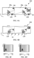
- FIG. 4A and FIG.4B respectively shows a side view and a top view of a system 100 for controlling a HVAC system 110 in a cabin 20 of a vehicle 10, where the cabin 20 is partially loaded with passengers 30, according to some embodiments.
- the solar radiation direction is indicated as arrows S2.
- the system 100 comprises a HVAC system 110 (not shown), a counting system 120, a camera 130, an infrared camera 140 (not shown) and a processor 150 (not shown).
- the counting system 120 is used to collect headcount data of passengers 30 in the cabin 20.
- the camera 130 is used to capture a plurality of images of an inside of the cabin 20 at different times.
- the infrared camera 140 is used to capture a plurality of infrared images of the inside of the cabin 20 at different times.
- FIG.3C shows an infrared image of the inside of a first part 20a of the cabin 20 of FIG.3A along the x-z plane captured by an infrared camera 140 combined with an image of the inside of the first part 20a of the cabin 20 of FIG. 3A along the x-z plane captured by the camera 130 (with only the passengers 30 shown in the image and with all background items such as seats removed from the image using computer vision).
- FIG.3D shows an infrared image of the inside of a second part 20b of the cabin 20 of FIG.3A along the x-z plane captured by an infrared camera 140 combined with an image of the inside of the second part 20b of the cabin 20 of FIG. 3A along the x-z plane captured by the camera 130 (with only the passengers 30 shown in the image and with all background items such as seats removed from the image using computer vision).
- FIG.4C shows an infrared image of the inside of a first part 20a of the cabin 20 of FIG.4A along the x-z plane captured by an infrared camera 140 combined with an image of the inside of the first part 20a of the cabin 20 of FIG. 4A along the x-z plane captured by the camera 130 (with only the passengers 30 shown in the image and with all background items such as seats removed from the image using computer vision).
- FIG.4D shows an infrared image of the inside of a second part 20b of the cabin 20 of FIG.4A along the x-z plane captured by an infrared camera 140 combined with an image of the inside of the second part 20b of the cabin 20 of FIG. 4A along the x-z plane captured by the camera 130 (with only the passengers 30 shown in the image and with all background items such as seats removed from the image using computer vision).
- Data of headcount of passengers 30 in the cabin 20 is obtained based on the images of the inside of the cabin 20 captured by the camera 130.
- the headcount data of the passengers 30 collected by the counting system 120 is then validated with the obtained data of headcount of the passengers 30.
- humidity and heat generation from the passengers 30 can be calculated based on the collected headcount data of the passengers 30.
- data of location and density of passengers 30 in the cabin 20 can also be obtained based on the images of the inside of the cabin 20 captured by the camera 130.
- the solar radiation direction and the solar thermal distribution along the cabin 20 can be obtained based on the infrared images of the inside of the cabin 20 captured by the infrared camera 140.
- Infiltration rate can be obtained from duration of opening of doors 22/24 of the vehicle 10.
- the obtained infiltration rates can be used for calculating the humidity and heat generation.
- Thermal loads are then obtained based on the collected headcount data of passengers 30, the obtained data of location and density of the passengers 30, the calculated humidity and heat generation, the obtained solar radiation direction and solar thermal distribution along the cabin 20, collected HVAC information and collected location and time based weather forecast data by the processor 150.
- the HVAC information can be collected from the HVAC system 110.
- the HVAC information can comprise in-cabin temperature, humidity and ventilation setting.
- the location and time based weather forecast data can comprise forecast data of location and time based solar radiation, temperature, humidity of the external environment outside the cabin 20.
- the processor 150 can be used to obtain optimal temperatures based on the obtained thermal loads.
- the system 100 comprises a HVAC controller 160 configured to set the optimal temperatures for the HVAC system 110.
- the processor 150 can be used to obtain optimal ventilation rates based on the obtained data of location and density of the passengers 30.
- the ventilation rate comprises air speed and air volume.
- In-cabin CO 2 level can be calculated based on the collected headcount data of the passengers 30.
- the in-cabin CO 2 level can be used for determining a ratio of fresh air over the recirculation air.
- PMV Predicted Mean Vote
- PMV method according to ASHRAE's standard no.55 is used to estimate right delivery air temperature, ventilation rate (air speed and air volume) and ventilation mode (recirculation and fresh air intake) based on the current thermal load, in-cabin temperature, relative humidity, CO 2 level for controlling the HVAC system that makes overall passengers comfortable.
- a method 800 is provided for controlling the HVAC system 110 in a cabin 20 of a vehicle 10, e.g., an electric vehicle 10.
- FIG. 5 is a flow chart depicting the method 800 for controlling the HVAC system 110 in a cabin 20 of a vehicle 10.
- the method 800 comprises:
- the method can further comprise:
- the method can further comprise:
- the method can further comprise a step 826 of obtaining optimal ventilation rates based on the obtained data of location and density of the passengers 30 by the processor 150, wherein the ventilation rate comprises air speed and air volume.
- the system and method in the present disclosure solves the problem of overcooling or overheating, e.g., when there are less passengers. It also maintains overall thermal comfort of the passenger along the transportation and enhances micro-climate management based on in-cabin passenger occupation.
- system and method in the present disclosure provides a more costeffective way of controlling the HVAC system of a vehicle as it does not require sampling by multiple sensors installed around the cabin.
Landscapes
- Engineering & Computer Science (AREA)
- Physics & Mathematics (AREA)
- Thermal Sciences (AREA)
- Mechanical Engineering (AREA)
- Life Sciences & Earth Sciences (AREA)
- Sustainable Development (AREA)
- Sustainable Energy (AREA)
- Air-Conditioning For Vehicles (AREA)
Abstract
Description
- This disclosure relates to a method and a system for controlling a heating, ventilation and air conditioning (HVAC) system in a cabin of a vehicle.
- Heating, ventilation and air conditioning (HVAC) system is the second largest on-board consumer of battery energy in electric vehicles such as light commercial transportation, vans or buses. For example, energy consumption per kilometer can grow up to 56% in electric buses due to the HVAC system usage.
- With limited specific reserve power on-board batteries, energy consumption due to HVAC can reduce the overall mileage range by 40% to 60% depending on running season (cooling or heating). On the other hand, due to almost half of the battery power goes to HVAC operations in high/low ambient temperature conditions, electric vehicles will have less mileage range than internal combustion engine (ICE) based transportation vehicles. This leads to a need for a larger battery which stores more energy and provides a longer battery life, therefore increasing total operating costs, to accomplish target mileage or less frequent charging in central charge stations.
- The mileage range can be increased by utilizing the energy saved through optimizing the HVAC system.
- In an implementation, a vehicle has a sensor system disposed adjacent to a headrest portion of a seat within a passenger compartment of the vehicle. The sensor system includes at least one of an air velocity sensor, an air temperature sensor, a radiant heat flux sensor, a heat flux sensor, or a humidity sensor. The sensor system provides data related to the air velocity, the air temperature, the radiant heat flux, the heat flux, or the relative humidity, enabling a climate controller to accurately calculate a current Equivalent Homogenous Temperature (EHT) of a passenger seated in the seat. The climate controller may then control a climate system of the vehicle based on the calculated EHT to provide a desired EHT.
- However, the sensor system requires multiple sampling and sensor installation around the cabin.
- A solution is needed to provide an improved method for controlling/optimizing the HVAC system in electric vehicles.
- This disclosure was conceptualized to assist in controlling/optimizing the HVAC system in vehicles, e.g., electric vehicles. The data of desired temperature, desired ventilation rate (desired air speed, desired air volume), desired ventilation mode (recirculation and fresh air intake) is obtained for controlling/optimizing the HVAC system in the vehicles.
- A technical solution is provided in the form of a method and a system for controlling/optimizing the HVAC system in electric vehicles.
- The system for controlling a HVAC system in a cabin of a vehicle comprising: a counting system configured to collect headcount data of passengers in the cabin; a camera configured to capture a plurality of images of an inside of the cabin at different times; a processor connected to the counting system and the camera, wherein the processor is configured to: obtain data of headcount of passengers in the cabin based on the captured images; validate the collected headcount data with the obtained data of headcount; and obtain thermal loads based on the collected headcount data, obtained data of location and density of the passengers, calculated humidity and heat generation, obtained solar thermal distribution along the cabin, collected HVAC information and collected location and time based weather forecast data.
- The method for controlling a HVAC system in a cabin of a vehicle comprising: collecting headcount data of passengers in the cabin by a counting system; capturing a plurality of images of an inside of the cabin at different times by a camera; obtaining data of headcount of passengers in the cabin based on the captured images by a processor;
validating the collected headcount data with the obtained data of headcount by the processor; obtaining thermal loads based on the collected headcount data, obtained data of location and density of the passengers, calculated humidity and heat generation, obtained solar thermal distribution along the cabin, collected HVAC information and collected location and time based weather forecast data by the processor. - The dependent claims define some examples associated with the system and method, respectively.
- The manual / semi-auto operation of the HVAC system is configured to eliminate overcooling or overheating, and overventilation, reduce total interaction of driver on HVAC controls, maintain overall thermal comfort of the passengers and enhance micro-climate management.
- The present disclosure will be better understood with reference to the detailed description when considered in conjunction with the non-limiting examples and the accompanying drawings, in which:
-
FIG.1 shows a schematic illustration of a vehicle having a cabin and a HVAC system. -
FIG.2 shows a schematic illustration of a system for controlling a HVAC system in a cabin of a vehicle. -
FIG.3A and FIG.3B respectively shows a side view and a top view of a system for controlling a HVAC system in a cabin of a vehicle, where the cabin is fully loaded with passengers. -
FIG.3C shows an infrared image captured by an infrared camera combined with an image captured by a camera of the inside of a first part of the cabin ofFIG.3A along the x-z plane. -
FIG.3D shows an infrared image combined with an image of the inside of a second part of the cabin ofFIG.3A along the x-z plane. -
FIG. 4A and FIG.4B respectively shows a side view and a top view of a system for controlling a HVAC system in a cabin of a vehicle, where the cabin is partially loaded with passengers. -
FIG.4C shows an infrared image combined with an image of the inside of a first part of the cabin ofFIG.4A along the x-z plane. -
FIG.4D shows an infrared image combined with an image of the inside of a second part of the cabin ofFIG.4A along the x-z plane. -
FIG.5 is a flow chart depicting the method for controlling the HVAC system in a cabin of a vehicle. - The following detailed description refers to the accompanying drawings that show, by way of illustration, specific details and embodiments in which the disclosure may be practiced. These embodiments are described in sufficient detail to enable those skilled in the art to practice the disclosure. Other embodiments may be utilized and structural, and logical changes may be made without departing from the scope of the disclosure. The various embodiments are not necessarily mutually exclusive, as some embodiments can be combined with one or more other embodiments to form new embodiments.
- Embodiments described in the context of one of the systems or methods are analogously valid for the other systems or methods.
- Features that are described in the context of an embodiment may correspondingly be applicable to the same or similar features in the other embodiments. Features that are described in the context of an embodiment may correspondingly be applicable to the other embodiments, even if not explicitly described in these other embodiments. Furthermore, additions and/or combinations and/or alternatives as described for a feature in the context of an embodiment may correspondingly be applicable to the same or similar feature in the other embodiments.
- In the context of various embodiments, the articles "a", "an" and "the" as used with regard to a feature or element include a reference to one or more of the features or elements.
- As used herein, the term "and/or" includes any and all combinations of one or more of the associated listed items.
- As used herein, the term "data" may be understood to include information in any suitable analog or digital form, for example, provided as a file, a portion of a file, a set of files, a signal or stream, a portion of a signal or stream, a set of signals or streams, and the like. The term data, however, is not limited to the aforementioned examples and may take various forms and represent any information as understood in the art.
- As used herein, the term "connected" can refer to a wired or wireless connection. Preferably, the connection between the at least one sensor and the graphic processing unit and/or the connection between the graphic processing unit and the display unit is a wired connection.
- According to an aspect of the disclosure, a
system 100 is provided for controlling a heating, ventilation and air conditioning (HVAC)system 110 in acabin 20 of avehicle 10, e.g., anelectric vehicle 10. - Many factors influence the energy requirements of a
HVAC system 110 in avehicle 10, such as headcount and location of thepassengers 30, solar radiation direction, solar radiation temperature, temperature and humidity of the external environment outside thecabin 20, etc. -
FIG. 1 shows a schematic illustration of avehicle 10 having acabin 20 and aHVAC system 110. There is an air and heat exchange among the external environment outside thecabin 20, thepassengers 30 in thecabin 20, thecabin 20 and theHVAC system 110. Fresh air flows from external environment into theHVAC system 110 as indicated by an arrow A1, supply air flows from theHVAC system 110 to thecabin 20 as indicated by an arrow A2, recirculation air flows from thecabin 20 to theHVAC system 110 as indicated by an arrow A3, exit air flows from thecabin 20 to the external environment as indicated by an arrow A4. There is also air exchange between thecabin 20 and the external environment through opening thedoors 22/24 of thevehicle 10 as indicated by arrows A5 and A6.Passengers 30 release vapor into thecabin 20 of thevehicle 10 as indicated by an arrow A7. Heat exchanges between theHVAC system 110 and thecabin 20 when the supply air flows from theHVAC system 110 to thecabin 20, and recirculation air flows from thecabin 20 to theHVAC system 110. Heat exchanges between the external environment and thecabin 20 when the fresh air flows from the environment to theHVAC system 110 and exit air flows from thecabin 20 to the external environment. Heat is released to thecabin 20 of thevehicle 10 through solar radiation as indicated by arrows A8.Passengers 30 also releases heat to thecabin 20 of thevehicle 10 as indicated by arrows A9. -
FIG.2 shows a schematic illustration of asystem 100 for controlling aHVAC system 110 in acabin 20 of avehicle 10. - As shown in
FIG.2 , thesystem 100 comprises acounting system 120, acamera 130 and aprocessor 150. Theprocessor 150 is connected to thecounting system 120 and thecamera 130. Theprocessor 150 can comprise a local server and/or a cloud server. - The
system 100 can also comprise aHVAC system 110, an infrared camera 140 and a HVAC controller 160. Theprocessor 150 can be connected to theHVAC system 110, the infrared camera 140 and the HVAC controller 160. - The
counting system 120 is configured to collect headcount data of thepassengers 30 in thecabin 20. The total headcount of thepassengers 30 in thecabin 20 of thevehicle 10 is changing with the time. In some embodiments, thecounting system 120 can be a tap in/out system, a light barrier system, a smart phone signal counting system which counts the smartphone signals (for example Wifi or Bluetooth signals), a weighing system, such as a scale, in the floor, or a ticket check system (local paper ticket or online ticket). Based on thecounting system 120 as a tap in/outsystem 120 for example, when apassenger 30 taps on the tap in/outsystem 120 when thepassenger 30 enters thecabin 20 of thevehicle 10 through anentrance door 22 of thevehicle 10, the tap in/outsystem 120 can add one to the total headcount of thepassengers 30 in thecabin 20. When apassenger 30 taps on the tap in/outsystem 120 when thepassenger 30 exits thecabin 20 through anexit door 24 of thevehicle 10, the tap in/outsystem 120 can subtract one from the total headcount of thepassengers 30 in thecabin 20. Based on thecounting system 120 as alight barrier system 120 for example, which is mounted next to the door(s) 22/24 of the vehicle, when apassenger 30 passes between the transmitter and receiver of thelight barrier system 120, i.e., when thepassenger 30 enters thecabin 20 of thevehicle 10 through anentrance door 22 of thevehicle 10, thelight barrier system 120 can add one to the total headcount of thepassengers 30 in thecabin 20. When apassenger 30 passes between the transmitter and receiver of thelight barrier system 120, i.e., when thepassenger 30 exits thecabin 20 through anexit door 24 of thevehicle 10, thelight barrier system 120 can subtract one from the total headcount of thepassengers 30 in thecabin 20. Based on thecounting system 120 as a smartphonesignal counting system 120 which counts the smartphone signals (for example Wifi or Bluetooth signals) for example, when apassenger 30 enters thevehicle 10, the smartphonesignal counting system 120 can detect the smartphone signals (for example Wifi or Bluetooth signals) from thepassenger 30 who enters thevehicle 10 and add one to the total headcount of thepassengers 30 in thecabin 20. When apassenger 30 exits thevehicle 10, the smartphonesignal counting system 120 is no longer able to detect the smartphone signals (for example Wifi or Bluetooth signals) from thepassenger 30 who exits thevehicle 10 and the smartphonesignal counting system 120 can subtract one from the total headcount of thepassengers 30 in thecabin 20. Based on thecounting system 120 as a weighingsystem 120, such as a scale, in the floor for example, which is mounted next to thedoors 22/24 of the vehicle, when apassenger 30 steps on the weighingsystem 120 when the passenger enters thecabin 20 of thevehicle 10 through anentrance door 22 of thevehicle 10, the weighingsystem 120 can add one to the total headcount of thepassengers 30 in thecabin 20. When apassenger 30 steps on the weighingsystem 120 when thepassenger 30 exits thecabin 20 through anexit door 24 of thevehicle 10, the weighingsystem 120 can subtract one from the total headcount of thepassengers 30 in thecabin 20. Based on thecounting system 120 as aticket check system 120 for example, when a local paper ticket or an online ticket of apassenger 30 is checked by theticket check system 120 when thepassenger 30 enters thecabin 20 of thevehicle 10 through anentrance door 22 of thevehicle 10, theticket check system 120 can add one to the total headcount of thepassengers 30 in thecabin 20. When a local paper ticket or an online ticket of apassenger 30 is checked by theticket check system 120 when thepassenger 30 exits thecabin 20 through anexit door 24 of thevehicle 10, theticket check system 120 can subtract one from the total headcount of thepassengers 30 in thecabin 20. - The
camera 130 is configured to capture a plurality of images of an inside of thecabin 20 at different times. The plurality of images can include images from a video or videos captured by thecamera 130. Theprocessor 150 is configured to obtain data of headcount ofpassengers 30 in thecabin 20 based on the captured images. Computer vision may be used to obtain the data of the headcount of thepassengers 30 based on the capture images. Theprocessor 150 is configured to validate the headcount data of thepassengers 30 collected by thecounting system 120 with the obtained data of headcount of thepassenger 30. - The
processor 150 can be used to calculate humidity and heat generation from thepassengers 30 based on the collected headcount data of thepassengers 30 and standard values from American Society of Heating, Refrigerating and Air-Conditioning Engineers (ASHRAE) standards. According to the ASHRAE standards, heat generation per person is around 100 watts, and water vapor generation is 70g/h when the passenger is seated and 90g/h when the passenger is standing. - The
processor 150 can be used to obtain infiltration rates based on duration of opening of thedoors 22/24 of thevehicle 10. The obtained infiltration rates can be used for calculating the humidity and heat generation. - The infrared camera 140 can be configured to detect thermal energy along the
cabin 20 and convert the thermal energy into an electrical signal, which is then processed to produce an infrared image. The infrared camera 140 can be configured to capture a plurality of infrared images of the inside of thecabin 20 at different times. Theprocessor 150 can be used to obtain solar radiation direction and solar thermal distribution along thecabin 20 based on the captured infrared images. The solar radiation direction and solar thermal distribution along thecabin 20 is changing with time. - The
processor 150 can obtain the data of location and density of thepassengers 30 in thecabin 20 based on the captured images of the inside of thecabin 20 at different times. The location and density of thepassengers 30 in thecabin 20 is changing with time. In addition, the data of the density of thepassengers 30 can be obtained by theprocessor 150 based on the collected headcount data of thepassengers 30 and the obtained data of location of thepassengers 30. Thepassenger 30 can compriseseating passengers 30 and/or standingpassengers 30. - The
processor 150 is configured to obtain thermal loads, the amount of heat energy required to add to or remove from thecabin 20 in order to maintain desired in-cabin temperature. The thermal load, the amount of heat energy required to add to or remove from thecabin 20 in order to maintain desired in-cabin temperature, is changing with time. The thermal loads are obtained based on the collected headcount data of thepassengers 30, obtained data of location and density of thepassengers 30, the calculated humidity and heat generation, the obtained solar radiation direction and solar thermal distribution along thecabin 20, collected HVAC information and collected location and time based weather forecast data by the processor. - The HVAC information can be collected from the HVAC system. The HVAC information can comprise in-cabin temperature, humidity and ventilation setting.
- The location and time based weather forecast data can comprise forecast data of location and time based solar radiation, temperature, humidity of the external environment outside the
cabin 20. -
FIG. 3A and FIG.3B respectively shows a side view and a top view of asystem 100 for controlling aHVAC system 110 in acabin 20 of avehicle 10, where thecabin 20 is fully loaded withpassengers 30, according to some embodiments. The solar radiation direction is indicated asarrows S 1. -
FIG. 4A and FIG.4B respectively shows a side view and a top view of asystem 100 for controlling aHVAC system 110 in acabin 20 of avehicle 10, where thecabin 20 is partially loaded withpassengers 30, according to some embodiments. The solar radiation direction is indicated as arrows S2. - As shown in
FIGs.3A-3B and4A-4B , thesystem 100 comprises a HVAC system 110 (not shown), acounting system 120, acamera 130, an infrared camera 140 (not shown) and a processor 150 (not shown). - The
counting system 120 is used to collect headcount data ofpassengers 30 in thecabin 20. - The
camera 130 is used to capture a plurality of images of an inside of thecabin 20 at different times. The infrared camera 140 is used to capture a plurality of infrared images of the inside of thecabin 20 at different times. -
FIG.3C shows an infrared image of the inside of afirst part 20a of thecabin 20 ofFIG.3A along the x-z plane captured by an infrared camera 140 combined with an image of the inside of thefirst part 20a of thecabin 20 ofFIG. 3A along the x-z plane captured by the camera 130 (with only thepassengers 30 shown in the image and with all background items such as seats removed from the image using computer vision).FIG.3D shows an infrared image of the inside of a second part 20b of thecabin 20 ofFIG.3A along the x-z plane captured by an infrared camera 140 combined with an image of the inside of the second part 20b of thecabin 20 ofFIG. 3A along the x-z plane captured by the camera 130 (with only thepassengers 30 shown in the image and with all background items such as seats removed from the image using computer vision). -
FIG.4C shows an infrared image of the inside of afirst part 20a of thecabin 20 ofFIG.4A along the x-z plane captured by an infrared camera 140 combined with an image of the inside of thefirst part 20a of thecabin 20 ofFIG. 4A along the x-z plane captured by the camera 130 (with only thepassengers 30 shown in the image and with all background items such as seats removed from the image using computer vision).FIG.4D shows an infrared image of the inside of a second part 20b of thecabin 20 ofFIG.4A along the x-z plane captured by an infrared camera 140 combined with an image of the inside of the second part 20b of thecabin 20 ofFIG. 4A along the x-z plane captured by the camera 130 (with only thepassengers 30 shown in the image and with all background items such as seats removed from the image using computer vision). - Data of headcount of
passengers 30 in thecabin 20 is obtained based on the images of the inside of thecabin 20 captured by thecamera 130. The headcount data of thepassengers 30 collected by thecounting system 120 is then validated with the obtained data of headcount of thepassengers 30. humidity and heat generation from thepassengers 30 can be calculated based on the collected headcount data of thepassengers 30. data of location and density ofpassengers 30 in thecabin 20 can also be obtained based on the images of the inside of thecabin 20 captured by thecamera 130. - The solar radiation direction and the solar thermal distribution along the
cabin 20 can be obtained based on the infrared images of the inside of thecabin 20 captured by the infrared camera 140. - Infiltration rate can be obtained from duration of opening of
doors 22/24 of thevehicle 10. The obtained infiltration rates can be used for calculating the humidity and heat generation. - Thermal loads are then obtained based on the collected headcount data of
passengers 30, the obtained data of location and density of thepassengers 30, the calculated humidity and heat generation, the obtained solar radiation direction and solar thermal distribution along thecabin 20, collected HVAC information and collected location and time based weather forecast data by theprocessor 150. - The HVAC information can be collected from the
HVAC system 110. The HVAC information can comprise in-cabin temperature, humidity and ventilation setting. - The location and time based weather forecast data can comprise forecast data of location and time based solar radiation, temperature, humidity of the external environment outside the
cabin 20. - The
processor 150 can be used to obtain optimal temperatures based on the obtained thermal loads. Thesystem 100 comprises a HVAC controller 160 configured to set the optimal temperatures for theHVAC system 110. - The
processor 150 can be used to obtain optimal ventilation rates based on the obtained data of location and density of thepassengers 30. The ventilation rate comprises air speed and air volume. - In-cabin CO2 level can be calculated based on the collected headcount data of the
passengers 30. The in-cabin CO2 level can be used for determining a ratio of fresh air over the recirculation air. - Predicted Mean Vote (PMV) is a method used to calculate human comfort. The predicted mean vote (PMV) was developed as an empirical fit to the human sensation of thermal comfort. It predicts the average vote of a large group of people on the a seven-point thermal sensation scale where: +3 = hot, +2 = warm, +1 = slightly warm, 0 = neutral, -1 = slightly cool, -2 = cool, -3 = cold. PMV method according to ASHRAE's standard no.55 is used to estimate right delivery air temperature, ventilation rate (air speed and air volume) and ventilation mode (recirculation and fresh air intake) based on the current thermal load, in-cabin temperature, relative humidity, CO2 level for controlling the HVAC system that makes overall passengers comfortable.
- According to another aspect of the disclosure, a
method 800 is provided for controlling theHVAC system 110 in acabin 20 of avehicle 10, e.g., anelectric vehicle 10.FIG. 5 is a flow chart depicting themethod 800 for controlling theHVAC system 110 in acabin 20 of avehicle 10. - The
method 800 comprises: - a
step 810 of collecting headcount data ofpassengers 30 in thecabin 20 by acounting system 120; - a
step 820 of capturing a plurality of images of an inside of thecabin 20 at different times by acamera 130; - a
step 822 of obtaining data of headcount ofpassengers 30 in thecabin 20 based on the captured images by aprocessor 150; - a
step 830 of validating the collected headcount data with the obtained data of headcount by theprocessor 150; - a
step 840 of obtaining thermal loads based on the collected headcount data, obtained data of location and density of thepassengers 30, calculated humidity and heat generation, obtained solar thermal distribution along thecabin 20, collected HVAC information and collected location and time based weather forecast data by theprocessor 150. - In some embodiments, the method can further comprise:
- a step of 812 of calculating the humidity and heat generation from the
passengers 30 based on the collected headcount data by theprocessor 150; - a step of 824 of obtaining the data of location and density of
passengers 30 in thecabin 20 based on the captured images by theprocessor 150; - a step 850 of obtaining infiltration rates from duration of opening of
doors 22/24 of thevehicle 10 by theprocessor 150, wherein the obtained infiltration rates are used for calculating the humidity and heat generation. - a step 860 of capturing a plurality of infrared images of the inside of the
cabin 20 at different times by an infrared camera 140; - a step 862 of obtaining solar radiation direction and solar thermal distribution along the
cabin 20 based on the captured infrared images by theprocessor 150. - In some embodiments, the method can further comprise:
- a step 842 of obtaining optimal temperatures based on the thermal loads; and
- a step 844 of setting, by a HVAC controller 160, the optimal temperatures for the
HVAC system 110. - In some embodiments, the method can further comprise a step 826 of obtaining optimal ventilation rates based on the obtained data of location and density of the
passengers 30 by theprocessor 150, wherein the ventilation rate comprises air speed and air volume. - Furthermore, one or more of the steps of a method described herein may be performed in parallel rather than sequentially.
- The system and method in the present disclosure solves the problem of overcooling or overheating, e.g., when there are less passengers. It also maintains overall thermal comfort of the passenger along the transportation and enhances micro-climate management based on in-cabin passenger occupation.
- In addition, the system and method in the present disclosure provides a more costeffective way of controlling the HVAC system of a vehicle as it does not require sampling by multiple sensors installed around the cabin.
- While the disclosure has been particularly shown and described with reference to specific embodiments, it should be understood by those skilled in the art that various changes in form and detail may be made therein without departing from the spirit and scope of the present disclosure as defined by the appended claims. The scope of the present disclosure is thus indicated by the appended claims and all changes which come within the meaning and range of equivalency of the claims are therefore intended to be embraced.
Claims (12)
- A method (800) for controlling a HVAC system (110) in a cabin (20) of a vehicle (10) comprising:a step (810) of collecting headcount data of passengers (30) in the cabin (20) by a counting system (120);a step (820) of capturing a plurality of images of an inside of the cabin (20) at different times by a camera (130);a step (822) of obtaining data of headcount of passengers (30) in the cabin (20) based on the captured images by a processor (150);a step (830) of validating the collected headcount data with the obtained data of headcount by the processor (150);a step (840) of obtaining thermal loads based on the collected headcount data, obtained data of location and density of the passengers (30), calculated humidity and heat generation, obtained solar thermal distribution along the cabin (20), collected HVAC information and collected location and time based weather forecast data by the processor (150).
- The method (800) of claim 1, further comprising:
a step of (812) of calculating the humidity and heat generation from the passengers (30) based on the collected headcount data by the processor (150). - The method (800) of claim 1, further comprising:
a step (850) of obtaining infiltration rates based on duration of opening of doors (22/24) of the vehicle (10) by the processor (150), wherein the obtained infiltration rates are used for calculating the humidity and heat generation. - The method (800) of claim 1, further comprising:a step (860) of capturing a plurality of infrared images of the inside of the cabin (20) at different times by an infrared camera (140);a step (862) of obtaining solar radiation direction and solar thermal distribution along the cabin (20) based on the captured infrared images by the processor (150).
- The method (800) of claim 1, further comprising:
a step of (824) of obtaining the data of location and density of passengers (30) in the cabin (20) based on the captured images by the processor (150). - The method (800) of claim 1, further comprising:
a step (842) of obtaining optimal temperatures based on the thermal loads. - The method (800) of claim 6, further comprising:
a step (844) of setting, by a HVAC controller (160), the optimal temperatures for the HVAC system (110). - The method (800) of claim 1, further comprising:
a step (826) of obtaining optimal ventilation rates based on the obtained data of location and density of the passengers (30) by the processor (150), wherein the ventilation rate comprises air speed and air volume. - The method (800) of claim 1, wherein the counting system (120) is a tap in/out system (120).
- A system (100) for controlling a HVAC system (110) in a cabin (20) of a vehicle (10) comprising:a counting system (120) configured to collect headcount data of passengers (30) in the cabin (20);a camera (130) configured to capture a plurality of images of an inside of the cabin (20) at different times;a processor (150) connected to the counting system (120) and the camera (130), wherein the processor (150) is configured to:obtain data of headcount of passengers (30) in the cabin (20) based on the captured images;validate the collected headcount data with the obtained data of headcount; andobtain thermal loads based on the collected headcount data, obtained data of location and density of the passengers (30), calculated humidity and heat generation, obtained solar thermal distribution along the cabin (20), collected HVAC information and collected location and time based weather forecast data.
- The system (100) of claim 10, further comprising:an infrared camera (140) configured to capture a plurality of infrared images of the inside of the cabin (20) at different times;wherein the processor (150) is connected to the infrared camera (140) and is configured to obtain solar radiation direction and solar thermal distribution along the cabin (20) based on the captured infrared images.
- The system (100) of claim 10, wherein the counting system (120) is a tap in/out system (120).
Priority Applications (2)
| Application Number | Priority Date | Filing Date | Title |
|---|---|---|---|
| EP22213748.1A EP4385772B1 (en) | 2022-12-15 | 2022-12-15 | System and method for controlling hvac system of vehicle |
| CN202311720181.0A CN118205359A (en) | 2022-12-15 | 2023-12-14 | System and method for controlling an HVAC system of a vehicle |
Applications Claiming Priority (1)
| Application Number | Priority Date | Filing Date | Title |
|---|---|---|---|
| EP22213748.1A EP4385772B1 (en) | 2022-12-15 | 2022-12-15 | System and method for controlling hvac system of vehicle |
Publications (2)
| Publication Number | Publication Date |
|---|---|
| EP4385772A1 true EP4385772A1 (en) | 2024-06-19 |
| EP4385772B1 EP4385772B1 (en) | 2025-11-05 |
Family
ID=84537373
Family Applications (1)
| Application Number | Title | Priority Date | Filing Date |
|---|---|---|---|
| EP22213748.1A Active EP4385772B1 (en) | 2022-12-15 | 2022-12-15 | System and method for controlling hvac system of vehicle |
Country Status (2)
| Country | Link |
|---|---|
| EP (1) | EP4385772B1 (en) |
| CN (1) | CN118205359A (en) |
Citations (4)
| Publication number | Priority date | Publication date | Assignee | Title |
|---|---|---|---|---|
| DE102015218205A1 (en) * | 2015-09-22 | 2017-03-23 | Siemens Aktiengesellschaft | Device for controlling a supply of fresh air in a vehicle |
| EP3326850A1 (en) * | 2016-11-29 | 2018-05-30 | Liebherr-Transportation Systems GmbH & Co. KG | Method for air conditioning a passenger compartment and air conditioning installation for a passenger compartment |
| EP3335919A1 (en) * | 2016-12-14 | 2018-06-20 | AURORA Konrad G. Schulz GmbH & Co. KG | Bus |
| DE202019101874U1 (en) * | 2018-04-04 | 2019-07-26 | Iveco France S.A.S. | System for controlling the air conditioning of a vehicle |
-
2022
- 2022-12-15 EP EP22213748.1A patent/EP4385772B1/en active Active
-
2023
- 2023-12-14 CN CN202311720181.0A patent/CN118205359A/en active Pending
Patent Citations (4)
| Publication number | Priority date | Publication date | Assignee | Title |
|---|---|---|---|---|
| DE102015218205A1 (en) * | 2015-09-22 | 2017-03-23 | Siemens Aktiengesellschaft | Device for controlling a supply of fresh air in a vehicle |
| EP3326850A1 (en) * | 2016-11-29 | 2018-05-30 | Liebherr-Transportation Systems GmbH & Co. KG | Method for air conditioning a passenger compartment and air conditioning installation for a passenger compartment |
| EP3335919A1 (en) * | 2016-12-14 | 2018-06-20 | AURORA Konrad G. Schulz GmbH & Co. KG | Bus |
| DE202019101874U1 (en) * | 2018-04-04 | 2019-07-26 | Iveco France S.A.S. | System for controlling the air conditioning of a vehicle |
Also Published As
| Publication number | Publication date |
|---|---|
| CN118205359A (en) | 2024-06-18 |
| EP4385772B1 (en) | 2025-11-05 |
Similar Documents
| Publication | Publication Date | Title |
|---|---|---|
| CN109733161B (en) | A kind of automobile air conditioning intelligent control method and vehicle-mounted system | |
| CN103303096B (en) | Control strategy for district heating, ventilation and the air handling system of vehicle | |
| JP7036706B2 (en) | Vehicle air conditioning control systems, vehicle air conditioning control methods, and programs | |
| CN101158496B (en) | Vehicle air conditioner and its control method | |
| CN109562672A (en) | The method controlled for the air conditioning components for motor vehicle | |
| US11014428B2 (en) | Controlling climate in vehicle cabins | |
| CN110239304B (en) | Control method and device for vehicle-mounted air conditioner | |
| US11648835B2 (en) | Smart grille shutter in connected vehicle | |
| CN111086367A (en) | Air conditioner control device, air conditioner control method, and storage medium | |
| CN105383444A (en) | Windshield defogging system and method | |
| JP2017501671A (en) | Method and apparatus for driving a vehicle | |
| US20190366793A1 (en) | Method and apparatus for control of vehicle ventilation in response to carbon dioxide estimation | |
| CN107010019A (en) | Save window defoggers and freeze prevention again | |
| US20190283531A1 (en) | Intelligent thermal control system for autonomous vehicle | |
| US20150097041A1 (en) | Vehicle comprising air conditioning apparatus | |
| DE102014202100A1 (en) | Detecting the presence of a person in a non-moving vehicle | |
| CN204757270U (en) | Three warm area air conditioner control system | |
| CN109094327A (en) | A kind of automobile mounted air-conditioning | |
| US12024154B2 (en) | Remotely control in-cabin features | |
| CN111354034A (en) | Image recognition system and method for estimating passenger surface area of rail transit | |
| DE102018218032A1 (en) | Vehicle control unit | |
| CN111845256A (en) | A kind of automobile air conditioning control method and system | |
| US20200324614A1 (en) | Air conditioning control system and air conditioning control method | |
| EP4385772B1 (en) | System and method for controlling hvac system of vehicle | |
| CN109109887B (en) | vehicle air conditioner temperature control method and system |
Legal Events
| Date | Code | Title | Description |
|---|---|---|---|
| PUAI | Public reference made under article 153(3) epc to a published international application that has entered the european phase |
Free format text: ORIGINAL CODE: 0009012 |
|
| STAA | Information on the status of an ep patent application or granted ep patent |
Free format text: STATUS: THE APPLICATION HAS BEEN PUBLISHED |
|
| AK | Designated contracting states |
Kind code of ref document: A1 Designated state(s): AL AT BE BG CH CY CZ DE DK EE ES FI FR GB GR HR HU IE IS IT LI LT LU LV MC ME MK MT NL NO PL PT RO RS SE SI SK SM TR |
|
| STAA | Information on the status of an ep patent application or granted ep patent |
Free format text: STATUS: REQUEST FOR EXAMINATION WAS MADE |
|
| 17P | Request for examination filed |
Effective date: 20241219 |
|
| GRAP | Despatch of communication of intention to grant a patent |
Free format text: ORIGINAL CODE: EPIDOSNIGR1 |
|
| STAA | Information on the status of an ep patent application or granted ep patent |
Free format text: STATUS: GRANT OF PATENT IS INTENDED |
|
| INTG | Intention to grant announced |
Effective date: 20250527 |
|
| GRAS | Grant fee paid |
Free format text: ORIGINAL CODE: EPIDOSNIGR3 |
|
| GRAA | (expected) grant |
Free format text: ORIGINAL CODE: 0009210 |
|
| STAA | Information on the status of an ep patent application or granted ep patent |
Free format text: STATUS: THE PATENT HAS BEEN GRANTED |
|
| AK | Designated contracting states |
Kind code of ref document: B1 Designated state(s): AL AT BE BG CH CY CZ DE DK EE ES FI FR GB GR HR HU IE IS IT LI LT LU LV MC ME MK MT NL NO PL PT RO RS SE SI SK SM TR |
|
| REG | Reference to a national code |
Ref country code: CH Ref legal event code: F10 Free format text: ST27 STATUS EVENT CODE: U-0-0-F10-F00 (AS PROVIDED BY THE NATIONAL OFFICE) Effective date: 20251105 Ref country code: GB Ref legal event code: FG4D |
|
| REG | Reference to a national code |
Ref country code: DE Ref legal event code: R096 Ref document number: 602022024350 Country of ref document: DE |
|
| REG | Reference to a national code |
Ref country code: IE Ref legal event code: FG4D |
|
| PGFP | Annual fee paid to national office [announced via postgrant information from national office to epo] |
Ref country code: AT Payment date: 20260113 Year of fee payment: 4 |
|
| PGFP | Annual fee paid to national office [announced via postgrant information from national office to epo] |
Ref country code: FR Payment date: 20251230 Year of fee payment: 4 |
|
| REG | Reference to a national code |
Ref country code: NL Ref legal event code: MP Effective date: 20251105 |
|
| PG25 | Lapsed in a contracting state [announced via postgrant information from national office to epo] |
Ref country code: ES Free format text: LAPSE BECAUSE OF FAILURE TO SUBMIT A TRANSLATION OF THE DESCRIPTION OR TO PAY THE FEE WITHIN THE PRESCRIBED TIME-LIMIT Effective date: 20251105 |
|
| REG | Reference to a national code |
Ref country code: LT Ref legal event code: MG9D |
|
| PG25 | Lapsed in a contracting state [announced via postgrant information from national office to epo] |
Ref country code: NO Free format text: LAPSE BECAUSE OF FAILURE TO SUBMIT A TRANSLATION OF THE DESCRIPTION OR TO PAY THE FEE WITHIN THE PRESCRIBED TIME-LIMIT Effective date: 20260205 |
|
| PGFP | Annual fee paid to national office [announced via postgrant information from national office to epo] |
Ref country code: DE Payment date: 20260223 Year of fee payment: 4 |
|
| PG25 | Lapsed in a contracting state [announced via postgrant information from national office to epo] |
Ref country code: AT Free format text: LAPSE BECAUSE OF FAILURE TO SUBMIT A TRANSLATION OF THE DESCRIPTION OR TO PAY THE FEE WITHIN THE PRESCRIBED TIME-LIMIT Effective date: 20251105 Ref country code: FI Free format text: LAPSE BECAUSE OF FAILURE TO SUBMIT A TRANSLATION OF THE DESCRIPTION OR TO PAY THE FEE WITHIN THE PRESCRIBED TIME-LIMIT Effective date: 20251105 Ref country code: HR Free format text: LAPSE BECAUSE OF FAILURE TO SUBMIT A TRANSLATION OF THE DESCRIPTION OR TO PAY THE FEE WITHIN THE PRESCRIBED TIME-LIMIT Effective date: 20251105 |
|
| PGFP | Annual fee paid to national office [announced via postgrant information from national office to epo] |
Ref country code: IT Payment date: 20251231 Year of fee payment: 4 |
|
| REG | Reference to a national code |
Ref country code: AT Ref legal event code: MK05 Ref document number: 1853988 Country of ref document: AT Kind code of ref document: T Effective date: 20251105 |
|
| PG25 | Lapsed in a contracting state [announced via postgrant information from national office to epo] |
Ref country code: NL Free format text: LAPSE BECAUSE OF FAILURE TO SUBMIT A TRANSLATION OF THE DESCRIPTION OR TO PAY THE FEE WITHIN THE PRESCRIBED TIME-LIMIT Effective date: 20251105 |
|
| PG25 | Lapsed in a contracting state [announced via postgrant information from national office to epo] |
Ref country code: RS Free format text: LAPSE BECAUSE OF FAILURE TO SUBMIT A TRANSLATION OF THE DESCRIPTION OR TO PAY THE FEE WITHIN THE PRESCRIBED TIME-LIMIT Effective date: 20260205 |
|
| PG25 | Lapsed in a contracting state [announced via postgrant information from national office to epo] |
Ref country code: IS Free format text: LAPSE BECAUSE OF FAILURE TO SUBMIT A TRANSLATION OF THE DESCRIPTION OR TO PAY THE FEE WITHIN THE PRESCRIBED TIME-LIMIT Effective date: 20260305 |
|
| PG25 | Lapsed in a contracting state [announced via postgrant information from national office to epo] |
Ref country code: PT Free format text: LAPSE BECAUSE OF FAILURE TO SUBMIT A TRANSLATION OF THE DESCRIPTION OR TO PAY THE FEE WITHIN THE PRESCRIBED TIME-LIMIT Effective date: 20260305 |
|
| PG25 | Lapsed in a contracting state [announced via postgrant information from national office to epo] |
Ref country code: PL Free format text: LAPSE BECAUSE OF FAILURE TO SUBMIT A TRANSLATION OF THE DESCRIPTION OR TO PAY THE FEE WITHIN THE PRESCRIBED TIME-LIMIT Effective date: 20251105 |
|
| PG25 | Lapsed in a contracting state [announced via postgrant information from national office to epo] |
Ref country code: LV Free format text: LAPSE BECAUSE OF FAILURE TO SUBMIT A TRANSLATION OF THE DESCRIPTION OR TO PAY THE FEE WITHIN THE PRESCRIBED TIME-LIMIT Effective date: 20251105 |