EP4385763A1 - System and method for estimation of remaining tire mileage - Google Patents
System and method for estimation of remaining tire mileage Download PDFInfo
- Publication number
- EP4385763A1 EP4385763A1 EP23215355.1A EP23215355A EP4385763A1 EP 4385763 A1 EP4385763 A1 EP 4385763A1 EP 23215355 A EP23215355 A EP 23215355A EP 4385763 A1 EP4385763 A1 EP 4385763A1
- Authority
- EP
- European Patent Office
- Prior art keywords
- tire
- mileage
- vehicle
- severity
- estimate
- Prior art date
- Legal status (The legal status is an assumption and is not a legal conclusion. Google has not performed a legal analysis and makes no representation as to the accuracy of the status listed.)
- Granted
Links
Images




Classifications
-
- B—PERFORMING OPERATIONS; TRANSPORTING
- B60—VEHICLES IN GENERAL
- B60C—VEHICLE TYRES; TYRE INFLATION; TYRE CHANGING; CONNECTING VALVES TO INFLATABLE ELASTIC BODIES IN GENERAL; DEVICES OR ARRANGEMENTS RELATED TO TYRES
- B60C11/00—Tyre tread bands; Tread patterns; Anti-skid inserts
- B60C11/24—Wear-indicating arrangements
- B60C11/246—Tread wear monitoring systems
Definitions
- the invention relates generally to tire monitoring systems and methods. More particularly, the invention relates to systems and methods that predict tire wear. Specifically, the invention is directed to a system and to a method for estimating the mileage that remains on a tire before replacement is needed, which takes a current wear state of the tire into account.
- Tire wear plays an important role in vehicle factors such as safety, reliability, and performance.
- Tread wear which refers to the loss of material from the tread of the tire, directly affects such vehicle factors.
- the invention relates to a system in accordance with claim 1 and to a method in accordance with claim 14.
- a system for estimating remaining mileage on a tire supporting a vehicle tire includes a processor that is in electronic communication with an electronic control system of the vehicle.
- a calibration module determines a wear rate of the tire, and the wear rate of the tire is communicated to the processor.
- a severity assessment module is in electronic communication with the processor. The severity assessment module receives real-time inputs and generates a real-time driving severity number.
- a mileage estimation module is in electronic communication with the processor and determines a current wear state of the tire. The mileage estimation module generates an estimate of remaining mileage on the tire from the wear rate of the tire, the real-time driving severity number, and the current wear state of the tire.
- ANN artificial neural network
- ANN artificial neural network
- Axial and “axially” means lines or directions that are parallel to the axis of rotation of the tire.
- CAN bus or "CAN bus system” is an abbreviation for controller area network system, which is a vehicle bus standard designed to allow microcontrollers and devices to communicate with each other within a vehicle without a host computer.
- “Circumferential” means lines or directions extending along the perimeter of the surface of the annular tread perpendicular to the axial direction.
- Equatorial centerplane means the plane perpendicular to the tire's axis of rotation and passing through the center of the tread.
- “Footprint” means the contact patch or area of contact created by the tire tread with a flat surface as the tire rotates or rolls.
- Inboard side means the side of the tire nearest the vehicle when the tire is mounted on a wheel and the wheel is mounted on the vehicle.
- “Lateral” means an axial direction.
- Outboard side means the side of the tire farthest away from the vehicle when the tire is mounted on a wheel and the wheel is mounted on the vehicle.
- Ring and radially means directions radially toward or away from the axis of rotation of the tire.
- Ring means a circumferentially extending strip of rubber on the tread which is defined by at least one circumferential groove and either a second such groove or a lateral edge, the strip being laterally undivided by full-depth grooves.
- Thread element or “traction element” means a rib or a block element defined by a shape having adjacent grooves.
- FIG. 1 an exemplary embodiment of the system 10 for estimating tire mileage tire of the present invention is presented.
- the system 10 forecasts replacement of each tire 12 supporting a vehicle 14.
- the position of each tire 12 on the vehicle 14 shall be referred to herein by way of example as front left position 12a, front right position 12b ( Figure 4 ), rear left position 12c, and rear right position 12d.
- the vehicle 14 is depicted as a passenger car, the invention is not to be so restricted.
- the principles of the invention find application in other vehicle categories, such as commercial trucks, in which vehicles may be supported by more or fewer tires than those shown in Figure 1 .
- the tires 12 are of conventional construction, and each tire is mounted on a respective wheel 16 as known to those skilled in the art.
- Each tire 12 includes a pair of sidewalls 18 that extend to a circumferential tread 20, which wears with age from road abrasion.
- An innerliner 22 is disposed on the inner surface of the tire 12, and when the tire is mounted on the wheel 16, an internal cavity 24 is formed, which is filled with a pressurized fluid, such as air.
- a tire sensor unit 26 may be attached to the innerliner 22 of each tire 12 by means such as an adhesive, and measures certain parameters or conditions of the tire, such as tire pressure and/or tire temperature, and may be of any known configuration. It is to be understood that the tire sensor unit 26 may be attached in such a manner, or to other components of the tire 12, such as on or in one of the sidewalls 18, on or in the tread 20, and/or on the wheel 16.
- the tire sensor unit 26 preferably also includes electronic memory capacity for storing identification (ID) information for each tire 12, known as tire ID information.
- aspects of the system for estimating tire mileage 10 preferably are executed on a processor 28.
- the processor 28 enables input of parameters and execution of specific techniques, to be described below, which are stored in a suitable storage medium and are in electronic communication with the processor.
- the processor 28 may be mounted on the vehicle 14, may be in communication with an electronic control system 30 of the vehicle, such as the vehicle CAN bus system, and/or may be a remote processor in a cloud-based server 32.
- Wireless transmission means 34 may wirelessly send data from sensors that are in electronic communication with the vehicle electronic control system 30 to the processor 28.
- Output from the system 10 may be wirelessly transmitted by an antenna 36 from the processor 28 to a display or controller device 38 and/or to the electronic control system 30 of the vehicle 14.
- the device 38 may include a device that is accessible to a user of the vehicle 14 or a technician for the vehicle, such as a smartphone, and/or a device that is accessible to a fleet manager, such as a computer.
- the system for estimating tire mileage 10 includes a calibration module 40, a severity assessment module 42, and a mileage estimation module 44.
- the system 10 outputs an estimate of remaining mileage 46 on each tire 12, as will be described in greater detail below.
- the term “tread wear” may be used interchangeably herein with the term “tire wear”.
- the calibration module 40 outputs a determination of a wear rate 48 of each tire 12, which is the amount of wear experienced by a tire over a defined period of time.
- the wear rate 48 is determined or quantified by operating the vehicle 14 over a known or predetermined route 50 that has a known or predetermined driving severity score 52.
- the driving severity score 52 takes into account the amount of turns, starts, and stops in the route 50. A route that includes more turns, more starts, and/or more stops than another route is considered to be more severe, and will thus have a higher driving severity score 52. A route that has a higher driving severity score 52 results in more wear on the tires 12 and thus a higher wear rate 48.
- a plot 54 of remaining tread depth 56 versus distance traveled 58 may be generated.
- the plot 54 yields a line 60 for each tire 12 on the vehicle 14.
- the slope of each line 60 provides the wear rate 48 for each respective tire 12.
- the wear rate 48 may be indexed or categorized according to each type of tire 12, such as by a stock keeping unit (SKU) number or other identifying number.
- SKU stock keeping unit
- the indexed wear rate 48 may be stored in an electronic memory that is stored on or transmitted to the processor 28.
- the wear rate 48 may be expressed as a rate for the front left 12a and front right 12b tire positions, and as a rate for the rear left 12c and rear right 12d positions.
- the severity assessment module 42 is stored on or is in electronic communication with the processor 28. With additional reference to Figure 5 , the severity assessment module 42 generates a real-time driving severity number 62.
- the real-time driving severity number 62 takes into account the amount of turns, starts and stops in the route driven by the vehicle 14, as described above, and the driving style of the driver of the vehicle. For example, more aggressive driving, such as aggressive starts and stops, generates more frictional energy, which increases tread wear.
- the severity assessment module 42 determines or quantifies the real-time driving severity number 62 by monitoring and receiving real-time inputs 70.
- the inputs 70 include a speed 64 of the vehicle 14 and linear accelerations of the vehicle, which include a longitudinal acceleration 66 and a lateral acceleration 68, measured over a pre-defined period or distance 86 of driving.
- the pre-defined period may be a driving distance of 500 kilometers (km).
- the speed 64 of the vehicle 14 may be obtained by a global positioning system (GPS) unit that is in electronic communication with an electronic control system 30 of the vehicle, such as the vehicle CAN bus system.
- the longitudinal acceleration 66 and lateral acceleration 68 may be measured with an inertial measurement unit 72 that is mounted on the vehicle 14 and may be included in a telematic control unit.
- a telematic control unit is a control and communication system that enables collection of vehicle data and transmission of the data to remote units or cloud computing services, and is preferably in electronic communication with an electronic control system 30 of the vehicle, such as the vehicle CAN bus system.
- the severity assessment module 42 may optionally receive additional inputs 74 to enhance the determination of the real-time driving severity number 62.
- the additional inputs 74 preferably include geolocation-based contextual data 76, as the position of the vehicle 14 is known from the GPS unit.
- the geolocation-based contextual data 76 may include weather conditions 78, such as temperature, humidity, and the like.
- the geolocation-based contextual data 76 may also include road topography 80, such as slope, curvature, and the like.
- the geolocation-based contextual data 76 may further include a road roughness index 82, such as an international roughness index (IRI), which is a roughness index obtained from measured longitudinal road profiles.
- IRI international roughness index
- the additional inputs 74 may be received from a remote service and/or from the cloud-based server 32.
- the severity assessment module 42 includes a driving severity number model 84, which receives the real-time inputs 70 and any additional inputs 74.
- the driving severity number model 84 determines the real-time driving severity number 62, which may correspond to a force severity on the tire 12.
- An exemplary technique that may be employed by the driving severity number model 84 includes a determination of force severity on the tire 12 as described in U.S. Patent Number 9,873,293 , which is owned by the same assignee as the present invention, The Goodyear Tire & Rubber Company, and is incorporated herein by reference.
- the driving severity number model 84 thus determines the real-time driving severity number 62, which may be expressed as a distribution 88 over the pre-defined driving period 86, as will be described in greater detail below.
- the mileage estimation module 44 is stored on or is in electronic communication with the processor 28.
- the mileage estimation module 44 includes a wear state estimator 90 that determines a current wear state 92 of the tire 12, which may be expressed as a tread depth of the tire. If the tire 12 is new, the current wear state 92 or tread depth may be known from a stock keeping unit (SKU) number or other identifying number of the tire.
- SKU stock keeping unit
- the current wear state 92 or tread depth may be determined by employing a wear estimation technique. Exemplary techniques are described in U.S. Patent Numbers 9,663,115 ; 9,878,721 ; 10,603,962 ; 9,821,611 ; 9,610,810 ; 9,873,293 ; 9,259,976 ; 9,050,864 ; 9,428,013 ; 9,442,045 ; and in U.S. Patent Application Publication Number 2020/0182746 .
- the current wear state 92 or tread depth may be determined by a manual measurement of the depth of the tread 20.
- the current wear state 92 may be expressed as a remaining tread depth for the front left 12a and front right 12b tire positions, and as a remaining tread depth for the rear left 12c and rear right 12d tire positions.
- the mileage estimation module 44 also includes a mileage projection model 94, which receives the current wear state 92 of the tire 12 from the wear state estimator 90.
- the mileage projection model 94 also receives the wear rate 48 and the driving severity score 52 over the known route 50 from the calibration module 40, and the driving severity number 62 from the severity assessment module 42.
- the mileage projection model 94 determines an estimate of remaining mileage 46 for the front left 12a and front right 12b tire positions, and an estimate of the remaining mileage for the tires for the rear left 12c and rear right 12d tire positions.
- Predicted mileage is the estimate of remaining mileage 46 for the rear left 12c and rear right 12d positions.
- Current Wear State is the current wear state 92 or tread depth of the tire 12 for the rear left 12c and rear right 12d positions from the wear state estimator 90.
- Cal_MinTread is a predetermined value of the depth of the tread 20 of the tire 12 at a minimum legal limit.
- Cal_MaxTread is a predetermined value of the depth of the tread 20 of the tire 12 when the tire is new.
- Cal_WearRateFront is the wear rate 48 of the front left 12a and front right 12b tire positions from the calibration module 40.
- DSN is the real-time driving severity number 62 from the driving severity number model 84.
- Cal_DSN_Avg is the driving severity score 52 over the known route 50 from the calibration module 40.
- the mileage estimation module 44 thus generates an estimate of remaining mileage 46 for the front left 12a and front right 12b tire positions, and an estimate of the remaining mileage for the rear left 12c and rear right 12d tire positions.
- the estimates of remaining mileage 46 preferably are in terms of distance, such as kilometers or miles.
- the estimates of remaining mileage 46 may be expressed as a prediction interval 96, rather than a single point estimate.
- the driving severity number model 84 may express driving severity as a distribution 88, a median value 98 of the distribution and a standard deviation 100 of the distribution may be employed in the mileage projection model 94 to generate the prediction interval 96 with a lower limit 102 and an upper limit 104.
- the lower limit 102 of the prediction interval 96 may be the median value 98 plus twice the standard deviation 100
- the upper limit 104 may be the median value minus twice the standard deviation.
- the system for estimating tire mileage 10 accurately and reliably estimates the mileage that remains on a tire 12 before replacement of the tire is needed, taking into account the current wear state of the tire and additional factors.
- the system for estimating tire mileage 10 includes the calibration module 40, the severity assessment module 42, and the mileage estimation module 44, to generate the estimate of remaining mileage 46 on each tire 12.
- the estimate of remaining mileage 46 may be wirelessly transmitted from the processor 28 to a display or controller device 38 and/or to the electronic control system 30 of the vehicle 14.
- the device 38 may include a device that is accessible to a user of the vehicle 14 or a technician for the vehicle, such as a smartphone, and/or a device that is accessible to a fleet manager, such as a computer.
- the estimate of remaining mileage 46 enables a user of the vehicle 14 to proactively schedule tire replacement as desired, and before a minimum wear threshold is reached.
- the estimate of remaining mileage 46 also enables a manager of a fleet of vehicles 14 to schedule tire replacement as preventive maintenance before the tire 12 reaches a minimum wear threshold.
- the estimate of remaining mileage 46 also enables service centers to optimize stock management, and enables tire manufacturers to optimize manufacturing operations.
- the present invention also includes a method for estimating tire mileage.
- the method includes steps in accordance with the description that is presented above and shown in Figures 1 through 6 .
- the above-described determinations of the system for estimating tire mileage 10 may be executed based upon measurements from a center of the tread 20 of each tire 12. It is to be understood that wear may additionally or alternatively be determined for other areas of the tread 20 of each tire 12, such as measurements from a shoulder of the tread, or from multiple areas of the tread, without affecting the overall concept or operation of the invention.
Landscapes
- Engineering & Computer Science (AREA)
- Mechanical Engineering (AREA)
- Tires In General (AREA)
- Physics & Mathematics (AREA)
- General Physics & Mathematics (AREA)
Abstract
Description
- The invention relates generally to tire monitoring systems and methods. More particularly, the invention relates to systems and methods that predict tire wear. Specifically, the invention is directed to a system and to a method for estimating the mileage that remains on a tire before replacement is needed, which takes a current wear state of the tire into account.
- Tire wear plays an important role in vehicle factors such as safety, reliability, and performance. Tread wear, which refers to the loss of material from the tread of the tire, directly affects such vehicle factors. As a result, it is desirable to monitor and/or measure the amount of tread wear experienced by a tire, which is indicated as the tire wear state. It is to be understood that for the purpose of convenience, the terms "tread wear" and "tire wear" may be used interchangeably.
- One approach to the monitoring and/or measurement of tread wear has been through the use of wear sensors disposed in the tire tread, which has been referred to as a direct method or approach. The direct approach to measuring tire wear from tire-mounted sensors has multiple challenges. Placing the sensors in an uncured or "green" tire to then be cured at high temperatures may cause damage to the wear sensors. In addition, sensor durability can prove to be an issue in meeting the millions of cycles requirement for tires. Moreover, wear sensors in a direct measurement approach must be small enough not to cause any uniformity problems as the tire rotates at high speeds. Finally, wear sensors can be expensive and add significantly to the cost of the tire.
- Due to such challenges, alternative approaches have been developed, which involve prediction of tread wear over the life of the tire, including indirect estimations of the tire wear state. These alternative approaches have experienced some disadvantages in the prior art due to a lack of optimum prediction techniques, which reduces the accuracy and/or reliability of the tread wear predictions. For example, many such techniques involve data or information that is not easily obtained, such as non-standard vehicle system signals, or data that is not accurate under all driving conditions.
- In addition, while some indirect estimation techniques have been developed that show improved accuracy and/or reliability, such techniques tend to indicate only the wear state of the tire. While such information is helpful, it may be of limited value for certain users. For example, some users may not fully understand an indication of tire wear state. In addition, many systems compare an estimated tire wear state to a threshold to inform the user that the tire should be replaced after the tire has reached a minimum wear state or threshold.
- However, it is often desirable to advise or notify a user well in advance of a wear threshold that a tire may need to be replaced. Such advance notice enables the user to proactively schedule tire replacement as desired, and before the minimum wear threshold is reached. Advance notice also enables a manager of a fleet of vehicles to schedule tire replacement as preventive maintenance before the tire reaches the minimum wear threshold. Monitoring of remaining tire mileage also enables service centers to optimize stock management, and enables tire manufacturers to optimize manufacturing operations.
- As a result, there is a need in the art for a system that accurately and reliably estimates the mileage that remains on a tire before replacement is needed, taking a current wear state of the tire into account.
- The invention relates to a system in accordance with claim 1 and to a method in accordance with
claim 14. - Dependent claims refer to preferred embodiments of the invention.
- According to an aspect of an exemplary embodiment of the invention, a system for estimating remaining mileage on a tire supporting a vehicle tire is provided. The system includes a processor that is in electronic communication with an electronic control system of the vehicle. A calibration module determines a wear rate of the tire, and the wear rate of the tire is communicated to the processor. A severity assessment module is in electronic communication with the processor. The severity assessment module receives real-time inputs and generates a real-time driving severity number. A mileage estimation module is in electronic communication with the processor and determines a current wear state of the tire. The mileage estimation module generates an estimate of remaining mileage on the tire from the wear rate of the tire, the real-time driving severity number, and the current wear state of the tire.
- The invention will be described by way of example and with reference to the accompanying drawings, in which:
-
Figure 1 is a schematic perspective view of a vehicle that includes tires employing an exemplary embodiment of a system for estimating tire mileage of the present invention; -
Figure 2 is a schematic representation of data transmission to a cloud-based server and to a device; -
Figure 3 is a schematic diagram of aspects of an exemplary embodiment of a system for estimating tire mileage of the present invention; -
Figure 4 is a schematic diagram of an aspect of the system for estimating tire mileage shown inFigure 3 ; -
Figure 5 is a schematic diagram of another aspect of the system for estimating tire mileage shown inFigure 3 ; and -
Figure 6 is a schematic diagram of another aspect of the system for estimating tire mileage shown inFigure 3 . - Similar numerals refer to similar parts throughout the drawings.
- "ANN" or "artificial neural network" is an adaptive tool for non-linear statistical data modeling that changes its structure based on external or internal information that flows through a network during a learning phase, used to model complex relationships between inputs and outputs or to find patterns in data.
- "Axial" and "axially" means lines or directions that are parallel to the axis of rotation of the tire.
- "CAN bus" or "CAN bus system" is an abbreviation for controller area network system, which is a vehicle bus standard designed to allow microcontrollers and devices to communicate with each other within a vehicle without a host computer.
- "Circumferential" means lines or directions extending along the perimeter of the surface of the annular tread perpendicular to the axial direction.
- "Equatorial centerplane" means the plane perpendicular to the tire's axis of rotation and passing through the center of the tread.
- "Footprint" means the contact patch or area of contact created by the tire tread with a flat surface as the tire rotates or rolls.
- "Inboard side" means the side of the tire nearest the vehicle when the tire is mounted on a wheel and the wheel is mounted on the vehicle.
- "Lateral" means an axial direction.
- "Outboard side" means the side of the tire farthest away from the vehicle when the tire is mounted on a wheel and the wheel is mounted on the vehicle.
- "Radial" and "radially" means directions radially toward or away from the axis of rotation of the tire.
- "Rib" means a circumferentially extending strip of rubber on the tread which is defined by at least one circumferential groove and either a second such groove or a lateral edge, the strip being laterally undivided by full-depth grooves.
- "Tread element" or "traction element" means a rib or a block element defined by a shape having adjacent grooves.
- With reference to
Figures 1 through 6 , an exemplary embodiment of thesystem 10 for estimating tire mileage tire of the present invention is presented. With particular reference toFigure 1 , thesystem 10 forecasts replacement of eachtire 12 supporting avehicle 14. The position of eachtire 12 on thevehicle 14 shall be referred to herein by way of example as frontleft position 12a, frontright position 12b (Figure 4 ), rearleft position 12c, and rearright position 12d. While thevehicle 14 is depicted as a passenger car, the invention is not to be so restricted. The principles of the invention find application in other vehicle categories, such as commercial trucks, in which vehicles may be supported by more or fewer tires than those shown inFigure 1 . - The
tires 12 are of conventional construction, and each tire is mounted on arespective wheel 16 as known to those skilled in the art. Eachtire 12 includes a pair ofsidewalls 18 that extend to acircumferential tread 20, which wears with age from road abrasion. Aninnerliner 22 is disposed on the inner surface of thetire 12, and when the tire is mounted on thewheel 16, aninternal cavity 24 is formed, which is filled with a pressurized fluid, such as air. - A
tire sensor unit 26 may be attached to theinnerliner 22 of eachtire 12 by means such as an adhesive, and measures certain parameters or conditions of the tire, such as tire pressure and/or tire temperature, and may be of any known configuration. It is to be understood that thetire sensor unit 26 may be attached in such a manner, or to other components of thetire 12, such as on or in one of thesidewalls 18, on or in thetread 20, and/or on thewheel 16. Thetire sensor unit 26 preferably also includes electronic memory capacity for storing identification (ID) information for eachtire 12, known as tire ID information. - Turning to
Figure 2 , aspects of the system for estimatingtire mileage 10 preferably are executed on aprocessor 28. Theprocessor 28 enables input of parameters and execution of specific techniques, to be described below, which are stored in a suitable storage medium and are in electronic communication with the processor. Theprocessor 28 may be mounted on thevehicle 14, may be in communication with anelectronic control system 30 of the vehicle, such as the vehicle CAN bus system, and/or may be a remote processor in a cloud-basedserver 32. - Wireless transmission means 34, such as an antenna, may wirelessly send data from sensors that are in electronic communication with the vehicle
electronic control system 30 to theprocessor 28. Output from thesystem 10 may be wirelessly transmitted by anantenna 36 from theprocessor 28 to a display orcontroller device 38 and/or to theelectronic control system 30 of thevehicle 14. By way of example, thedevice 38 may include a device that is accessible to a user of thevehicle 14 or a technician for the vehicle, such as a smartphone, and/or a device that is accessible to a fleet manager, such as a computer. - Turning to
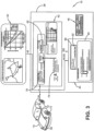
Figure 3 , the system for estimatingtire mileage 10 includes acalibration module 40, aseverity assessment module 42, and amileage estimation module 44. Thesystem 10 outputs an estimate of remainingmileage 46 on eachtire 12, as will be described in greater detail below. It is to be noted that, for the purpose of convenience, the term "tread wear" may be used interchangeably herein with the term "tire wear". - With additional reference to
Figure 4 , thecalibration module 40 outputs a determination of awear rate 48 of eachtire 12, which is the amount of wear experienced by a tire over a defined period of time. Preferably, thewear rate 48 is determined or quantified by operating thevehicle 14 over a known orpredetermined route 50 that has a known or predetermineddriving severity score 52. The drivingseverity score 52 takes into account the amount of turns, starts, and stops in theroute 50. A route that includes more turns, more starts, and/or more stops than another route is considered to be more severe, and will thus have a higherdriving severity score 52. A route that has a higherdriving severity score 52 results in more wear on thetires 12 and thus ahigher wear rate 48. - By operating the
vehicle 14 over theroute 50 with a known drivingseverity score 52, aplot 54 of remainingtread depth 56 versus distance traveled 58 may be generated. Theplot 54 yields aline 60 for eachtire 12 on thevehicle 14. The slope of eachline 60 provides thewear rate 48 for eachrespective tire 12. Thewear rate 48 may be indexed or categorized according to each type oftire 12, such as by a stock keeping unit (SKU) number or other identifying number. The indexedwear rate 48 may be stored in an electronic memory that is stored on or transmitted to theprocessor 28. Thewear rate 48 may be expressed as a rate for the front left 12a and front right 12b tire positions, and as a rate for the rear left 12c and rear right 12d positions. - Returning to
Figure 3 , theseverity assessment module 42 is stored on or is in electronic communication with theprocessor 28. With additional reference toFigure 5 , theseverity assessment module 42 generates a real-time drivingseverity number 62. The real-time drivingseverity number 62 takes into account the amount of turns, starts and stops in the route driven by thevehicle 14, as described above, and the driving style of the driver of the vehicle. For example, more aggressive driving, such as aggressive starts and stops, generates more frictional energy, which increases tread wear. - The
severity assessment module 42 determines or quantifies the real-time drivingseverity number 62 by monitoring and receiving real-time inputs 70. Theinputs 70 include aspeed 64 of thevehicle 14 and linear accelerations of the vehicle, which include alongitudinal acceleration 66 and alateral acceleration 68, measured over a pre-defined period ordistance 86 of driving. By way of example, the pre-defined period may be a driving distance of 500 kilometers (km). - The
speed 64 of thevehicle 14 may be obtained by a global positioning system (GPS) unit that is in electronic communication with anelectronic control system 30 of the vehicle, such as the vehicle CAN bus system. Thelongitudinal acceleration 66 andlateral acceleration 68 may be measured with aninertial measurement unit 72 that is mounted on thevehicle 14 and may be included in a telematic control unit. A telematic control unit is a control and communication system that enables collection of vehicle data and transmission of the data to remote units or cloud computing services, and is preferably in electronic communication with anelectronic control system 30 of the vehicle, such as the vehicle CAN bus system. - The
severity assessment module 42 may optionally receiveadditional inputs 74 to enhance the determination of the real-time drivingseverity number 62. Theadditional inputs 74 preferably include geolocation-basedcontextual data 76, as the position of thevehicle 14 is known from the GPS unit. The geolocation-basedcontextual data 76 may includeweather conditions 78, such as temperature, humidity, and the like. The geolocation-basedcontextual data 76 may also includeroad topography 80, such as slope, curvature, and the like. The geolocation-basedcontextual data 76 may further include aroad roughness index 82, such as an international roughness index (IRI), which is a roughness index obtained from measured longitudinal road profiles. Theadditional inputs 74 may be received from a remote service and/or from the cloud-basedserver 32. - The
severity assessment module 42 includes a drivingseverity number model 84, which receives the real-time inputs 70 and anyadditional inputs 74. The drivingseverity number model 84 determines the real-time drivingseverity number 62, which may correspond to a force severity on thetire 12. An exemplary technique that may be employed by the drivingseverity number model 84 includes a determination of force severity on thetire 12 as described inU.S. Patent Number 9,873,293 severity number model 84 thus determines the real-time drivingseverity number 62, which may be expressed as adistribution 88 over thepre-defined driving period 86, as will be described in greater detail below. - Returning to
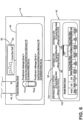
Figure 3 , themileage estimation module 44 is stored on or is in electronic communication with theprocessor 28. With additional reference toFigure 6 , themileage estimation module 44 includes awear state estimator 90 that determines acurrent wear state 92 of thetire 12, which may be expressed as a tread depth of the tire. If thetire 12 is new, thecurrent wear state 92 or tread depth may be known from a stock keeping unit (SKU) number or other identifying number of the tire. - If the
tire 12 is worn, thecurrent wear state 92 or tread depth may be determined by employing a wear estimation technique. Exemplary techniques are described inU.S. Patent Numbers 9,663,115 9,878,721 10,603,962 9,821,611 9,610,810 9,873,293 9,259,976 9,050,864 9,428,013 9,442,045 U.S. Patent Application Publication Number 2020/0182746 . Alternatively, if thetire 12 is worn, thecurrent wear state 92 or tread depth may be determined by a manual measurement of the depth of thetread 20. Thecurrent wear state 92 may be expressed as a remaining tread depth for the front left 12a and front right 12b tire positions, and as a remaining tread depth for the rear left 12c and rear right 12d tire positions. - The
mileage estimation module 44 also includes amileage projection model 94, which receives thecurrent wear state 92 of thetire 12 from thewear state estimator 90. Themileage projection model 94 also receives thewear rate 48 and the drivingseverity score 52 over the knownroute 50 from thecalibration module 40, and the drivingseverity number 62 from theseverity assessment module 42. Preferably, themileage projection model 94 determines an estimate of remainingmileage 46 for the front left 12a and front right 12b tire positions, and an estimate of the remaining mileage for the tires for the rear left 12c and rear right 12d tire positions. - Preferably, the
mileage projection model 94 determines an estimate of remainingmileage 46 for the front left 12a and front right 12b tire positions as follows:
- Where:
- Predicted mileage is the estimate of remaining
mileage 46 for the front left 12a and front right 12b tire positions. - Current Wear State is the
current wear state 92 or tread depth of thetire 12 for the front left 12a and front right 12b tire positions from thewear state estimator 90. - Cal_MinTread is a predetermined value of the depth of the
tread 20 of thetire 12 at a minimum legal limit. - Cal_MaxTread is a predetermined value of the depth of the
tread 20 of thetire 12 when the tire is new. - Cal_WearRateFront is the
wear rate 48 of the front left 12a and front right 12b tire positions from thecalibration module 40. - DSN is the real-time driving
severity number 62 from the drivingseverity number model 84. - Cal_DSN_Avg is the driving
severity score 52 over the knownroute 50 from thecalibration module 40. - Preferably, the
mileage projection model 94 determines an estimate of remainingmileage 46 for the rear left 12c and rear right 12d tire positions as follows:
- Where:
Predicted mileage is the estimate of remainingmileage 46 for the rear left 12c and rear right 12d positions. - Current Wear State is the
current wear state 92 or tread depth of thetire 12 for the rear left 12c and rear right 12d positions from thewear state estimator 90. - Cal_MinTread is a predetermined value of the depth of the
tread 20 of thetire 12 at a minimum legal limit. - Cal_MaxTread is a predetermined value of the depth of the
tread 20 of thetire 12 when the tire is new. - Cal_WearRateFront is the
wear rate 48 of the front left 12a and front right 12b tire positions from thecalibration module 40. - DSN is the real-time driving
severity number 62 from the drivingseverity number model 84. - Cal_DSN_Avg is the driving
severity score 52 over the knownroute 50 from thecalibration module 40. - Through the
mileage projection model 94, themileage estimation module 44 thus generates an estimate of remainingmileage 46 for the front left 12a and front right 12b tire positions, and an estimate of the remaining mileage for the rear left 12c and rear right 12d tire positions. The estimates of remainingmileage 46 preferably are in terms of distance, such as kilometers or miles. In addition, the estimates of remainingmileage 46 may be expressed as aprediction interval 96, rather than a single point estimate. - More particularly, because the driving
severity number model 84 may express driving severity as adistribution 88, amedian value 98 of the distribution and astandard deviation 100 of the distribution may be employed in themileage projection model 94 to generate theprediction interval 96 with a lower limit 102 and anupper limit 104. For example, the lower limit 102 of theprediction interval 96 may be themedian value 98 plus twice thestandard deviation 100, while theupper limit 104 may be the median value minus twice the standard deviation. - In this manner, the system for estimating
tire mileage 10 accurately and reliably estimates the mileage that remains on atire 12 before replacement of the tire is needed, taking into account the current wear state of the tire and additional factors. As described above, the system for estimatingtire mileage 10 includes thecalibration module 40, theseverity assessment module 42, and themileage estimation module 44, to generate the estimate of remainingmileage 46 on eachtire 12. - The estimate of remaining
mileage 46 may be wirelessly transmitted from theprocessor 28 to a display orcontroller device 38 and/or to theelectronic control system 30 of thevehicle 14. Thedevice 38 may include a device that is accessible to a user of thevehicle 14 or a technician for the vehicle, such as a smartphone, and/or a device that is accessible to a fleet manager, such as a computer. The estimate of remainingmileage 46 enables a user of thevehicle 14 to proactively schedule tire replacement as desired, and before a minimum wear threshold is reached. The estimate of remainingmileage 46 also enables a manager of a fleet ofvehicles 14 to schedule tire replacement as preventive maintenance before thetire 12 reaches a minimum wear threshold. The estimate of remainingmileage 46 also enables service centers to optimize stock management, and enables tire manufacturers to optimize manufacturing operations. - The present invention also includes a method for estimating tire mileage. The method includes steps in accordance with the description that is presented above and shown in
Figures 1 through 6 . - It is to be understood that the structure of the above-described system for estimating tire mileage tire may be altered or rearranged, or components or steps known to those skilled in the art omitted or added, without affecting the overall concept or operation of the invention. For example, electronic communication may be through a wired connection or wireless communication without affecting the overall concept or operation of the invention. Such wireless communications include radio frequency (RF) and Bluetooth® communications.
- In addition, the above-described determinations of the system for estimating
tire mileage 10 may be executed based upon measurements from a center of thetread 20 of eachtire 12. It is to be understood that wear may additionally or alternatively be determined for other areas of thetread 20 of eachtire 12, such as measurements from a shoulder of the tread, or from multiple areas of the tread, without affecting the overall concept or operation of the invention.
Claims (15)
- A system for estimating remaining mileage on a tire (12) supporting a vehicle (14), the system (10) comprising:a processor (28) in electronic communication with an electronic control system (30) of the vehicle (14);a calibration module (40) configured for determining a wear rate of the tire (12) and for communicating the wear rate of the tire (12) to the processor (28);a severity assessment module (42) in electronic communication with the processor (28), the severity assessment module being configured for receiving real-time inputs and generating a real-time driving severity number; anda mileage estimation module (44) in electronic communication with the processor (28), the mileage estimation module being configured for determining a current wear state of the tire (12) and for generating an estimate of remaining mileage on the tire from the wear rate of the tire, the real-time driving severity number, and the current wear state of the tire.
- The system of claim 1, wherein in the calibration module (40) is configured to determine the wear rate of the tire (12) from a plot of remaining tread depth versus distance traveled over a predetermined route, wherein the route includes a predetermined driving severity score.
- The system of claim 1 or 2, wherein the wear rate is expressed as a first rate for front left and front right tire positions, and as a second rate for rear left and rear right tire positions.
- The system of at least one of the previous claims, wherein real-time inputs received by the severity assessment module (42) include a speed of the vehicle, a longitudinal acceleration of the vehicle, and a lateral acceleration of the vehicle; and/or wherein the real-time inputs received by the severity assessment module (42) include geolocation-based contextual data, said geolocation-based contextual data preferably including at least one or two or all of weather condition data, road topography data and a road roughness index.
- The system of at least one of the previous claims, wherein the real-time inputs received by the severity assessment module (42) are measured over a pre-defined driving period.
- The system of at least one of the previous claims, wherein the real-time driving severity number generated by the severity assessment module (42) is expressed as a distribution over the pre-defined driving period.
- The system of at least one of the previous claims, wherein the current wear state of the tire (12) is expressed as a first remaining tread depth for front left and front right tire positions, and as a second remaining tread depth for rear left and rear right tire positions.
- The system of at least one of the previous claims, wherein the mileage estimation module (44) includes a wear state estimator (90) for determining the current wear state of the tire (12).
- The system of at least one of the previous claims, wherein the mileage estimation module (44) includes a mileage projection model (94), the mileage projection model being configured for receiving the current wear state of the tire from the wear state estimator (90), the wear rate from the calibration module (40), and the driving severity number from the severity assessment module (42).
- The system of at least one of the previous claims, wherein the mileage projection model (94) is configured to receive a predetermined driving severity score from the calibration module (40) and for employing the predetermined driving severity score in the generation of the estimate of remaining mileage on the tire (12).
- The system of at least one of the previous claims, wherein the mileage projection model (94) is configured to receive a predetermined value of a depth of a tread of the tire (12) at a minimum legal limit and for employing the predetermined value in the generation of the estimate of remaining mileage on the tire; and/or wherein the mileage projection model (94) is configured to receive a predetermined value of a depth of a tread of the tire (12) when the tire is new and for employing the predetermined value in the generation of the estimate of remaining mileage on the tire.
- The system of at least one of the previous claims, wherein the estimate of remaining mileage is determined as a first estimate of remaining mileage for front left and front right tire positions, and as a second estimate of remaining mileage for rear left and rear right tire positions; and/or wherein the estimate of remaining mileage is expressed as a prediction interval, the prediction interval including a lower limit and an upper limit.
- The system of at least one of the previous claims, wherein the estimate of remaining mileage is electronically communicated to a device that is accessible to at least one of a user of the vehicle, a technician for the vehicle, and a fleet manager.
- A method of estimating remaining mileage on a tire (12) supporting a vehicle (14), the method comprising:providing a processor (28) in electronic communication with an electronic control system (30) of the vehicle (14);providing a calibration module (40), the calibration module (40) determining a wear rate of the tire (12) and communicating the wear rate of the tire (12) to the processor (28);providing a severity assessment module (42) in electronic communication with the processor (28), the severity assessment module receiving real-time inputs and generating a real-time driving severity number; andproviding a mileage estimation module (44) in electronic communication with the processor (28), the mileage estimation module determining a current wear state of the tire (12) and generating an estimate of remaining mileage on the tire from the wear rate of the tire, the real-time driving severity number, and the current wear state of the tire.
- The method of claim 14 wherein the method is executed using a system in accordance with at least one of the claims 1 to 13.
Applications Claiming Priority (2)
| Application Number | Priority Date | Filing Date | Title |
|---|---|---|---|
| US202263387153P | 2022-12-13 | 2022-12-13 | |
| US18/509,772 US20240192093A1 (en) | 2022-12-13 | 2023-11-15 | System for estimation of remaining tire mileage |
Publications (2)
| Publication Number | Publication Date |
|---|---|
| EP4385763A1 true EP4385763A1 (en) | 2024-06-19 |
| EP4385763B1 EP4385763B1 (en) | 2025-09-17 |
Family
ID=89164584
Family Applications (1)
| Application Number | Title | Priority Date | Filing Date |
|---|---|---|---|
| EP23215355.1A Active EP4385763B1 (en) | 2022-12-13 | 2023-12-08 | System and method for estimation of remaining tire mileage |
Country Status (2)
| Country | Link |
|---|---|
| US (1) | US20240192093A1 (en) |
| EP (1) | EP4385763B1 (en) |
Citations (16)
| Publication number | Priority date | Publication date | Assignee | Title |
|---|---|---|---|---|
| US9050864B2 (en) | 2013-06-14 | 2015-06-09 | The Goodyear Tire & Rubber Company | Tire wear state estimation system and method |
| US9259976B2 (en) | 2013-08-12 | 2016-02-16 | The Goodyear Tire & Rubber Company | Torsional mode tire wear state estimation system and method |
| US9428013B2 (en) | 2013-08-22 | 2016-08-30 | The Goodyear Tire & Rubber Company | Tire wear state estimation system utilizing cornering stiffness and method |
| US9442045B2 (en) | 2014-04-03 | 2016-09-13 | The Goodyear Tire & Rubber Company | Model-based longitudinal stiffness estimation system and method |
| US9610810B1 (en) | 2015-10-21 | 2017-04-04 | The Goodyear Tire & Rubber Company | Method of tire state estimation through wheel speed signal feature extraction |
| US9663115B2 (en) | 2015-10-09 | 2017-05-30 | The Goodyear Tire & Rubber Company | Method for estimating tire forces from CAN-bus accessible sensor inputs |
| US9821611B2 (en) | 2015-10-21 | 2017-11-21 | The Goodyear Tire & Rubber Company | Indirect tire wear state estimation system |
| US9873293B2 (en) | 2015-10-21 | 2018-01-23 | The Goodyear Tire & Rubber Company | Indirect tire wear state prediction system and method |
| US9878721B2 (en) | 2015-11-11 | 2018-01-30 | The Goodyear Tire & Rubber Company | Tire sensor-based robust mileage tracking system and method |
| US20190265129A1 (en) * | 2016-06-09 | 2019-08-29 | Bridgestone Corporation | Tire management device and tire management program |
| US10603962B2 (en) | 2017-06-29 | 2020-03-31 | The Goodyear Tire & Rubber Company | Tire wear state estimation system and method |
| US20200182746A1 (en) | 2018-12-11 | 2020-06-11 | The Goodyear Tire & Rubber Company | Tire wear state estimation system and method |
| KR20220077285A (en) * | 2020-12-01 | 2022-06-09 | 주식회사 호원 | Apparatus and method for measuring tire wear of a vehicle |
| JP2022143401A (en) * | 2021-03-17 | 2022-10-03 | Toyo Tire株式会社 | WEAR Amount Estimating System, Calculation Model Generating System, and WEAR Amount Estimating Method |
| US20220324266A1 (en) * | 2021-04-09 | 2022-10-13 | GM Global Technology Operations LLC | Systems and methods for estimating tire wear |
| US20220371382A1 (en) * | 2019-10-21 | 2022-11-24 | Bridgestone Corporation | Tire wear amount estimation system, tire wear amount estimation program, and tire wear amount estimation method |
Family Cites Families (11)
| Publication number | Priority date | Publication date | Assignee | Title |
|---|---|---|---|---|
| JP4840122B2 (en) * | 2006-12-18 | 2011-12-21 | 横浜ゴム株式会社 | Acceleration analysis apparatus, acceleration analysis method, and software program |
| US9376118B2 (en) * | 2014-07-08 | 2016-06-28 | The Goodyear Tire & Rubber Company | Assessment of tire condition based on a tire health parameter |
| CN108712972A (en) * | 2016-03-09 | 2018-10-26 | 米其林集团总公司 | Vehicle Integrated Expected Tread Life Indication System |
| US10518590B2 (en) * | 2018-03-05 | 2019-12-31 | Sensata Technologies, Inc. | System and method for tracking tire tread wear |
| IT201800007884A1 (en) * | 2018-08-06 | 2020-02-06 | Bridgestone Europe Nv Sa | SYSTEM AND METHOD FOR MONITORING THE CONSUMPTION OF TREAD |
| US10889152B2 (en) * | 2018-11-23 | 2021-01-12 | Toyota Motor North America, Inc. | Systems, apparatus, and methods to determine vehicle tire wear |
| JP7329068B2 (en) * | 2019-04-01 | 2023-08-17 | ブリヂストン アメリカズ タイヤ オペレーションズ、 エルエルシー | Systems and methods for vehicle tire performance modeling and feedback |
| JP7454366B2 (en) * | 2019-12-11 | 2024-03-22 | Toyo Tire株式会社 | Vehicle driving condition evaluation method and system |
| JP7602974B2 (en) * | 2021-06-25 | 2024-12-19 | 株式会社ブリヂストン | Tire wear prediction system |
| EP4194230B1 (en) * | 2021-12-13 | 2024-11-20 | Bridgestone Europe NV/SA | Apparatus and methods for calculating and/or monitoring a tire wear rate of a vehicle |
| US12319097B2 (en) * | 2022-08-31 | 2025-06-03 | Ford Global Technologies, Llc | System and method for monitoring tire tread and recommending a tire rotation service |
-
2023
- 2023-11-15 US US18/509,772 patent/US20240192093A1/en active Pending
- 2023-12-08 EP EP23215355.1A patent/EP4385763B1/en active Active
Patent Citations (16)
| Publication number | Priority date | Publication date | Assignee | Title |
|---|---|---|---|---|
| US9050864B2 (en) | 2013-06-14 | 2015-06-09 | The Goodyear Tire & Rubber Company | Tire wear state estimation system and method |
| US9259976B2 (en) | 2013-08-12 | 2016-02-16 | The Goodyear Tire & Rubber Company | Torsional mode tire wear state estimation system and method |
| US9428013B2 (en) | 2013-08-22 | 2016-08-30 | The Goodyear Tire & Rubber Company | Tire wear state estimation system utilizing cornering stiffness and method |
| US9442045B2 (en) | 2014-04-03 | 2016-09-13 | The Goodyear Tire & Rubber Company | Model-based longitudinal stiffness estimation system and method |
| US9663115B2 (en) | 2015-10-09 | 2017-05-30 | The Goodyear Tire & Rubber Company | Method for estimating tire forces from CAN-bus accessible sensor inputs |
| US9610810B1 (en) | 2015-10-21 | 2017-04-04 | The Goodyear Tire & Rubber Company | Method of tire state estimation through wheel speed signal feature extraction |
| US9821611B2 (en) | 2015-10-21 | 2017-11-21 | The Goodyear Tire & Rubber Company | Indirect tire wear state estimation system |
| US9873293B2 (en) | 2015-10-21 | 2018-01-23 | The Goodyear Tire & Rubber Company | Indirect tire wear state prediction system and method |
| US9878721B2 (en) | 2015-11-11 | 2018-01-30 | The Goodyear Tire & Rubber Company | Tire sensor-based robust mileage tracking system and method |
| US20190265129A1 (en) * | 2016-06-09 | 2019-08-29 | Bridgestone Corporation | Tire management device and tire management program |
| US10603962B2 (en) | 2017-06-29 | 2020-03-31 | The Goodyear Tire & Rubber Company | Tire wear state estimation system and method |
| US20200182746A1 (en) | 2018-12-11 | 2020-06-11 | The Goodyear Tire & Rubber Company | Tire wear state estimation system and method |
| US20220371382A1 (en) * | 2019-10-21 | 2022-11-24 | Bridgestone Corporation | Tire wear amount estimation system, tire wear amount estimation program, and tire wear amount estimation method |
| KR20220077285A (en) * | 2020-12-01 | 2022-06-09 | 주식회사 호원 | Apparatus and method for measuring tire wear of a vehicle |
| JP2022143401A (en) * | 2021-03-17 | 2022-10-03 | Toyo Tire株式会社 | WEAR Amount Estimating System, Calculation Model Generating System, and WEAR Amount Estimating Method |
| US20220324266A1 (en) * | 2021-04-09 | 2022-10-13 | GM Global Technology Operations LLC | Systems and methods for estimating tire wear |
Also Published As
| Publication number | Publication date |
|---|---|
| US20240192093A1 (en) | 2024-06-13 |
| EP4385763B1 (en) | 2025-09-17 |
Similar Documents
| Publication | Publication Date | Title |
|---|---|---|
| CN112440628B (en) | Tire wear estimation system and method using footprint length | |
| EP3378679B1 (en) | Model based tire wear estimation system and method | |
| EP3960505B1 (en) | Tire wear state estimation system and method | |
| EP3785944B1 (en) | Tire wear state estimation system and method employing footprint shape factor | |
| EP3838628A1 (en) | Method of estimating tire conditions | |
| EP4197822B1 (en) | Tire replacement system and method | |
| US11827229B2 (en) | Method for estimating tire grip | |
| EP4101659B1 (en) | Tire replacement forecasting system and method | |
| EP3957501B1 (en) | Tire high temperature forecasting system and method | |
| US20200182746A1 (en) | Tire wear state estimation system and method | |
| EP4385762B1 (en) | System and method for estimation of tire tread depth employing wheel speed | |
| EP4385763B1 (en) | System and method for estimation of remaining tire mileage | |
| US20240174034A1 (en) | Tire rolling resistance estimation system | |
| EP4140838A1 (en) | Road condition monitoring system and method | |
| CN118182019A (en) | Tire remaining mileage estimation system | |
| CN116278523B (en) | Tire changing system | |
| CN118182018A (en) | System for estimating tire tread depth using wheel speed | |
| BR102022010187B1 (en) | TIRE REPLACEMENT PREDICTION SYSTEM | |
| CN118107594A (en) | Tire rolling resistance estimation system | |
| CN118024792A (en) | Method and system for monitoring tire inflation pressure |
Legal Events
| Date | Code | Title | Description |
|---|---|---|---|
| PUAI | Public reference made under article 153(3) epc to a published international application that has entered the european phase |
Free format text: ORIGINAL CODE: 0009012 |
|
| STAA | Information on the status of an ep patent application or granted ep patent |
Free format text: STATUS: THE APPLICATION HAS BEEN PUBLISHED |
|
| AK | Designated contracting states |
Kind code of ref document: A1 Designated state(s): AL AT BE BG CH CY CZ DE DK EE ES FI FR GB GR HR HU IE IS IT LI LT LU LV MC ME MK MT NL NO PL PT RO RS SE SI SK SM TR |
|
| STAA | Information on the status of an ep patent application or granted ep patent |
Free format text: STATUS: REQUEST FOR EXAMINATION WAS MADE |
|
| 17P | Request for examination filed |
Effective date: 20241203 |
|
| RBV | Designated contracting states (corrected) |
Designated state(s): AL AT BE BG CH CY CZ DE DK EE ES FI FR GB GR HR HU IE IS IT LI LT LU LV MC ME MK MT NL NO PL PT RO RS SE SI SK SM TR |
|
| GRAP | Despatch of communication of intention to grant a patent |
Free format text: ORIGINAL CODE: EPIDOSNIGR1 |
|
| STAA | Information on the status of an ep patent application or granted ep patent |
Free format text: STATUS: GRANT OF PATENT IS INTENDED |
|
| RIC1 | Information provided on ipc code assigned before grant |
Ipc: B60C 11/24 20060101AFI20250321BHEP |
|
| INTG | Intention to grant announced |
Effective date: 20250423 |
|
| GRAS | Grant fee paid |
Free format text: ORIGINAL CODE: EPIDOSNIGR3 |
|
| GRAA | (expected) grant |
Free format text: ORIGINAL CODE: 0009210 |
|
| STAA | Information on the status of an ep patent application or granted ep patent |
Free format text: STATUS: THE PATENT HAS BEEN GRANTED |
|
| AK | Designated contracting states |
Kind code of ref document: B1 Designated state(s): AL AT BE BG CH CY CZ DE DK EE ES FI FR GB GR HR HU IE IS IT LI LT LU LV MC ME MK MT NL NO PL PT RO RS SE SI SK SM TR |
|
| REG | Reference to a national code |
Ref country code: GB Ref legal event code: FG4D |
|
| REG | Reference to a national code |
Ref country code: CH Ref legal event code: EP |
|
| REG | Reference to a national code |
Ref country code: DE Ref legal event code: R096 Ref document number: 602023006777 Country of ref document: DE |
|
| REG | Reference to a national code |
Ref country code: IE Ref legal event code: FG4D |
|
| PGFP | Annual fee paid to national office [announced via postgrant information from national office to epo] |
Ref country code: DE Payment date: 20251126 Year of fee payment: 3 |
|
| PG25 | Lapsed in a contracting state [announced via postgrant information from national office to epo] |
Ref country code: NO Free format text: LAPSE BECAUSE OF FAILURE TO SUBMIT A TRANSLATION OF THE DESCRIPTION OR TO PAY THE FEE WITHIN THE PRESCRIBED TIME-LIMIT Effective date: 20251217 |
|
| REG | Reference to a national code |
Ref country code: LT Ref legal event code: MG9D |
|
| PGFP | Annual fee paid to national office [announced via postgrant information from national office to epo] |
Ref country code: AT Payment date: 20260113 Year of fee payment: 3 |
|
| PG25 | Lapsed in a contracting state [announced via postgrant information from national office to epo] |
Ref country code: FI Free format text: LAPSE BECAUSE OF FAILURE TO SUBMIT A TRANSLATION OF THE DESCRIPTION OR TO PAY THE FEE WITHIN THE PRESCRIBED TIME-LIMIT Effective date: 20250917 |
|
| PG25 | Lapsed in a contracting state [announced via postgrant information from national office to epo] |
Ref country code: HR Free format text: LAPSE BECAUSE OF FAILURE TO SUBMIT A TRANSLATION OF THE DESCRIPTION OR TO PAY THE FEE WITHIN THE PRESCRIBED TIME-LIMIT Effective date: 20250917 |
|
| PGFP | Annual fee paid to national office [announced via postgrant information from national office to epo] |
Ref country code: FR Payment date: 20251120 Year of fee payment: 3 |
|
| PG25 | Lapsed in a contracting state [announced via postgrant information from national office to epo] |
Ref country code: GR Free format text: LAPSE BECAUSE OF FAILURE TO SUBMIT A TRANSLATION OF THE DESCRIPTION OR TO PAY THE FEE WITHIN THE PRESCRIBED TIME-LIMIT Effective date: 20251218 |
|
| PG25 | Lapsed in a contracting state [announced via postgrant information from national office to epo] |
Ref country code: SE Free format text: LAPSE BECAUSE OF FAILURE TO SUBMIT A TRANSLATION OF THE DESCRIPTION OR TO PAY THE FEE WITHIN THE PRESCRIBED TIME-LIMIT Effective date: 20250917 |
|
| REG | Reference to a national code |
Ref country code: NL Ref legal event code: MP Effective date: 20250917 |
|
| PG25 | Lapsed in a contracting state [announced via postgrant information from national office to epo] |
Ref country code: LV Free format text: LAPSE BECAUSE OF FAILURE TO SUBMIT A TRANSLATION OF THE DESCRIPTION OR TO PAY THE FEE WITHIN THE PRESCRIBED TIME-LIMIT Effective date: 20250917 |
|
| PG25 | Lapsed in a contracting state [announced via postgrant information from national office to epo] |
Ref country code: BG Free format text: LAPSE BECAUSE OF FAILURE TO SUBMIT A TRANSLATION OF THE DESCRIPTION OR TO PAY THE FEE WITHIN THE PRESCRIBED TIME-LIMIT Effective date: 20250917 |
|
| PG25 | Lapsed in a contracting state [announced via postgrant information from national office to epo] |
Ref country code: RS Free format text: LAPSE BECAUSE OF FAILURE TO SUBMIT A TRANSLATION OF THE DESCRIPTION OR TO PAY THE FEE WITHIN THE PRESCRIBED TIME-LIMIT Effective date: 20251217 |
|
| PG25 | Lapsed in a contracting state [announced via postgrant information from national office to epo] |
Ref country code: NL Free format text: LAPSE BECAUSE OF FAILURE TO SUBMIT A TRANSLATION OF THE DESCRIPTION OR TO PAY THE FEE WITHIN THE PRESCRIBED TIME-LIMIT Effective date: 20250917 |
|
| REG | Reference to a national code |
Ref country code: AT Ref legal event code: MK05 Ref document number: 1838022 Country of ref document: AT Kind code of ref document: T Effective date: 20250917 |
|
| PG25 | Lapsed in a contracting state [announced via postgrant information from national office to epo] |
Ref country code: SM Free format text: LAPSE BECAUSE OF FAILURE TO SUBMIT A TRANSLATION OF THE DESCRIPTION OR TO PAY THE FEE WITHIN THE PRESCRIBED TIME-LIMIT Effective date: 20250917 |
|
| PG25 | Lapsed in a contracting state [announced via postgrant information from national office to epo] |
Ref country code: ES Free format text: LAPSE BECAUSE OF FAILURE TO SUBMIT A TRANSLATION OF THE DESCRIPTION OR TO PAY THE FEE WITHIN THE PRESCRIBED TIME-LIMIT Effective date: 20250917 |
|
| PG25 | Lapsed in a contracting state [announced via postgrant information from national office to epo] |
Ref country code: AT Free format text: LAPSE BECAUSE OF FAILURE TO SUBMIT A TRANSLATION OF THE DESCRIPTION OR TO PAY THE FEE WITHIN THE PRESCRIBED TIME-LIMIT Effective date: 20250917 |
|
| PG25 | Lapsed in a contracting state [announced via postgrant information from national office to epo] |
Ref country code: RO Free format text: LAPSE BECAUSE OF FAILURE TO SUBMIT A TRANSLATION OF THE DESCRIPTION OR TO PAY THE FEE WITHIN THE PRESCRIBED TIME-LIMIT Effective date: 20250917 Ref country code: IT Free format text: LAPSE BECAUSE OF FAILURE TO SUBMIT A TRANSLATION OF THE DESCRIPTION OR TO PAY THE FEE WITHIN THE PRESCRIBED TIME-LIMIT Effective date: 20250917 |
|
| PG25 | Lapsed in a contracting state [announced via postgrant information from national office to epo] |
Ref country code: IS Free format text: LAPSE BECAUSE OF FAILURE TO SUBMIT A TRANSLATION OF THE DESCRIPTION OR TO PAY THE FEE WITHIN THE PRESCRIBED TIME-LIMIT Effective date: 20260117 |
|
| PG25 | Lapsed in a contracting state [announced via postgrant information from national office to epo] |
Ref country code: PT Free format text: LAPSE BECAUSE OF FAILURE TO SUBMIT A TRANSLATION OF THE DESCRIPTION OR TO PAY THE FEE WITHIN THE PRESCRIBED TIME-LIMIT Effective date: 20260119 Ref country code: CZ Free format text: LAPSE BECAUSE OF FAILURE TO SUBMIT A TRANSLATION OF THE DESCRIPTION OR TO PAY THE FEE WITHIN THE PRESCRIBED TIME-LIMIT Effective date: 20250917 |
|
| PG25 | Lapsed in a contracting state [announced via postgrant information from national office to epo] |
Ref country code: PL Free format text: LAPSE BECAUSE OF FAILURE TO SUBMIT A TRANSLATION OF THE DESCRIPTION OR TO PAY THE FEE WITHIN THE PRESCRIBED TIME-LIMIT Effective date: 20250917 |
|
| PG25 | Lapsed in a contracting state [announced via postgrant information from national office to epo] |
Ref country code: SK Free format text: LAPSE BECAUSE OF FAILURE TO SUBMIT A TRANSLATION OF THE DESCRIPTION OR TO PAY THE FEE WITHIN THE PRESCRIBED TIME-LIMIT Effective date: 20250917 Ref country code: EE Free format text: LAPSE BECAUSE OF FAILURE TO SUBMIT A TRANSLATION OF THE DESCRIPTION OR TO PAY THE FEE WITHIN THE PRESCRIBED TIME-LIMIT Effective date: 20250917 |
|
| REG | Reference to a national code |
Ref country code: DE Ref legal event code: R097 Ref document number: 602023006777 Country of ref document: DE |
|
| PG25 | Lapsed in a contracting state [announced via postgrant information from national office to epo] |
Ref country code: LT Free format text: LAPSE BECAUSE OF FAILURE TO SUBMIT A TRANSLATION OF THE DESCRIPTION OR TO PAY THE FEE WITHIN THE PRESCRIBED TIME-LIMIT Effective date: 20250917 |
|
| PG25 | Lapsed in a contracting state [announced via postgrant information from national office to epo] |
Ref country code: MC Free format text: LAPSE BECAUSE OF FAILURE TO SUBMIT A TRANSLATION OF THE DESCRIPTION OR TO PAY THE FEE WITHIN THE PRESCRIBED TIME-LIMIT Effective date: 20250917 |
|
| PG25 | Lapsed in a contracting state [announced via postgrant information from national office to epo] |
Ref country code: DK Free format text: LAPSE BECAUSE OF FAILURE TO SUBMIT A TRANSLATION OF THE DESCRIPTION OR TO PAY THE FEE WITHIN THE PRESCRIBED TIME-LIMIT Effective date: 20250917 |
|
| PLBE | No opposition filed within time limit |
Free format text: ORIGINAL CODE: 0009261 |
|
| STAA | Information on the status of an ep patent application or granted ep patent |
Free format text: STATUS: NO OPPOSITION FILED WITHIN TIME LIMIT |
|
| REG | Reference to a national code |
Ref country code: CH Ref legal event code: L10 Free format text: ST27 STATUS EVENT CODE: U-0-0-L10-L00 (AS PROVIDED BY THE NATIONAL OFFICE) Effective date: 20260729 |