EP4385308A1 - Automatic row guidance nudge for agricultural vehicles - Google Patents
Automatic row guidance nudge for agricultural vehicles Download PDFInfo
- Publication number
- EP4385308A1 EP4385308A1 EP23216063.0A EP23216063A EP4385308A1 EP 4385308 A1 EP4385308 A1 EP 4385308A1 EP 23216063 A EP23216063 A EP 23216063A EP 4385308 A1 EP4385308 A1 EP 4385308A1
- Authority
- EP
- European Patent Office
- Prior art keywords
- nudge
- crop rows
- vehicle
- alignment
- steering
- Prior art date
- Legal status (The legal status is an assumption and is not a legal conclusion. Google has not performed a legal analysis and makes no representation as to the accuracy of the status listed.)
- Pending
Links
- 238000000034 method Methods 0.000 claims abstract description 23
- 238000012545 processing Methods 0.000 claims description 14
- 238000012937 correction Methods 0.000 claims description 10
- 230000008569 process Effects 0.000 claims description 10
- 210000004894 snout Anatomy 0.000 claims description 8
- 230000007423 decrease Effects 0.000 claims 2
- 230000004075 alteration Effects 0.000 claims 1
- 230000003466 anti-cipated effect Effects 0.000 claims 1
- 230000008859 change Effects 0.000 abstract description 4
- 238000001514 detection method Methods 0.000 description 9
- 238000013459 approach Methods 0.000 description 8
- 241000143973 Libytheinae Species 0.000 description 4
- 238000010586 diagram Methods 0.000 description 4
- 238000005516 engineering process Methods 0.000 description 4
- 238000003306 harvesting Methods 0.000 description 4
- 241001124569 Lycaenidae Species 0.000 description 2
- 230000008901 benefit Effects 0.000 description 2
- 241000196324 Embryophyta Species 0.000 description 1
- 240000008042 Zea mays Species 0.000 description 1
- 235000005824 Zea mays ssp. parviglumis Nutrition 0.000 description 1
- 235000002017 Zea mays subsp mays Nutrition 0.000 description 1
- 230000003190 augmentative effect Effects 0.000 description 1
- 238000012512 characterization method Methods 0.000 description 1
- 238000006243 chemical reaction Methods 0.000 description 1
- 230000000295 complement effect Effects 0.000 description 1
- 230000001143 conditioned effect Effects 0.000 description 1
- 230000003750 conditioning effect Effects 0.000 description 1
- 235000005822 corn Nutrition 0.000 description 1
- 238000009313 farming Methods 0.000 description 1
- 238000012986 modification Methods 0.000 description 1
- 230000004048 modification Effects 0.000 description 1
- 238000012544 monitoring process Methods 0.000 description 1
- 239000000047 product Substances 0.000 description 1
- 230000002250 progressing effect Effects 0.000 description 1
- 230000000284 resting effect Effects 0.000 description 1
- 239000013589 supplement Substances 0.000 description 1
- 230000007723 transport mechanism Effects 0.000 description 1
Images



Classifications
-
- A—HUMAN NECESSITIES
- A01—AGRICULTURE; FORESTRY; ANIMAL HUSBANDRY; HUNTING; TRAPPING; FISHING
- A01D—HARVESTING; MOWING
- A01D41/00—Combines, i.e. harvesters or mowers combined with threshing devices
- A01D41/12—Details of combines
- A01D41/127—Control or measuring arrangements specially adapted for combines
- A01D41/1278—Control or measuring arrangements specially adapted for combines for automatic steering
Definitions
- the present disclosure relates generally to systems and methods for nudging steering of agricultural vehicles.
- Agricultural vehicles designed to harvest row crops pose unique issues with properly following rows in a field being harvested.
- rows of the crops e.g., stalks
- furrows in the field may be detected and used as a basis for guiding steering of the harvesting vehicles.
- more complex sensing technologies such as GPS location can be used to identify locations that may be compared to a map of the field for such purposes.
- a row guidance system guides to a calibrated row sensor voltage based on a center resting position of the sensor or its associated detection members. Due to the mounting location on the vehicle, guiding to this centered voltage is not always ideal for row tracking, such as on curves and hillsides.
- a system comprises a sensing arrangement that in operation senses alignment of an agricultural vehicle with two reference crop rows, the sensing arrangement outputting a reference alignment signal representative of relative closeness to the two reference crop rows.
- Processing circuitry receives and processes the reference alignment signal to regulate steering of the vehicle. For correction of alignment of the vehicle with the reference crop rows the processing circuitry implements a nudge by altering the reference alignment signal.
- the disclosure provides an improved and straightforward approach to adapting row crop steering guidance to accommodate changes required by actual field conditions.
- the techniques implemented may utilize past row sensor data to apply an offset to the target voltage of the sensor improving row tracking during curve and hillside operation. This offset could be calculated based on sensor characterization data placed into a steering model.
- the disclosed techniques may be used in conjunction with existing technologies, such as the advanced farming system available under the commercial designation AFS from Case IH. Changes in steering, sometimes referred to herein as "nudges" may be implemented on the fly, and in control approaches that may be open loop (e.g., operator input or authorized) or closed loop (e.g., automatic without operator input).
- FIG. 1 is a diagrammatical representation of an exemplary row crop harvester according to the present disclosure.
- the illustration of FIG. 1 is of a row harvester 10, such as for harvesting corn.
- a row harvester 10 such as for harvesting corn.
- headers 12 such as for harvesting different crops.
- header snouts 14 extend in front of the vehicle and serve to grasp, cut, and convey stalks and grains into the harvester as it progresses through a field.
- the crop 16 will present, in such applications, rows 18 that are generally aligned with one another and that were defined during planting in a conventional manner.
- the vehicle is typically driven by a human operator occupying the vehicle cab 20. As discussed below, the operator will be provided in the cab with means for steering the vehicle, and with an interface to monitor and control its operation.
- the harvester As the harvester progresses in the field, it will cut and partially process the harvested product, such as by at least partial removal of grain from the cut crop.
- the separated grain may be transferred from the vehicle by a spout 22 which may contain an auger or other transport mechanisms.
- a grain cart or other collection vehicle will typically track beside the harvester to receive the harvested grain from the spout 22.
- Progress through the field, as indicated by arrow 24 will follow the direction of the rows such that the individual plants in each row will properly align with the header snouts to ensure proper cutting and processing.
- crops in the rows are detected and feedback from such detection may be used to help guide the steering of the vehicle to ensure alignment with the rows.
- steady state errors may occur and build that could result in deviation from the desired path aligned with the rows.
- the disclosed techniques provide for real or near-real time correction of the steering with or without prior knowledge of the field and crop topologies.
- FIGS. 2A and 2B are diagrammatical views of portions of row harvesters illustrating scenarios in which the improved guidance techniques of the disclosure may be used.
- Sensing of the crops in the rows may be done by physical contact of wands 26 that protrude from one or more of the header snouts 14a, 14b and 14c, as shown in the figures, in this case from snout 14b.
- a sensor 28 is coupled to the wands and provides a feedback signal indicating relative closeness to the two rows between which the instrumented snout is passing.
- a potentiometer may produce a known voltage when the wands are "centered", such as 2.5 volts. This center voltage may be calibrated to ensure that when "centered" (i.e., not contacting crop on either side), a known voltage signal is output.
- the sensor feedback in some cases in combination with other data, such as past steering data, position system data (e.g., GPS data) may be used to steer the vehicle to ensure proper alignment with the crop rows.
- position system data e.g., GPS data
- this control may satisfactorily control steering in a closed loop manner with little correction needed.
- segments of the field such as in curves or turns, however, as shown in FIG. 2B , the vehicle must progress in a curvilinear path as indicated by arrow 32.
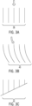
- FIGS. 3A-3C are diagrammatical views three scenarios in which the disclosed improvements may be advantageous.
- scenario 38 may correspond to a straight section of a field, where crop rows are aligned in straight lines.
- Scenario 40 corresponds to curved sections or turns where radii of curvature may be constant or changing. These will typically follow and lead other straight sections, so that the guidance should be highly adaptable either in open or closed loop control.
- Scenario 42 of FIG. 3C occurs with crops are planted on an incline or hill.
- the vehicle will need to follow the rows along the hill, that is, traverse to the direction of incline.
- the vehicle may have a tendency to slide or creep slightly downhill, steering corrections may be required.
- contact may be more frequent with the downhill side of the header snout, and this can be corrected for by nudging the steering in the uphill direction.
- FIG. 4 is a block diagram of exemplary functional components of a system for nudging steering guidance of a row harvester.
- the steering nudge system 44 comprises sensor inputs on which steering corrections may be based.
- these include one or more row sensors 46 of the type described above.
- Wheel position or steering sensors 48 may provide signals representative of the current steering positions (e.g., angles) of steered wheels of the vehicle.
- Outside position sensors, such as GPS position inputs 50 may be provided that can help in situating the vehicle in a field, and in monitoring tracking as movement of the vehicle proceeds.
- Other sensors 52 may also be present and used as inputs, such as cameras, terrain detection sensors, and so forth.
- the sensor inputs may be applied to any suitable signal conditioning circuitry 54 that may that may perform signal conversion, scaling, and any other desired operations.
- the conditioned and/or processed signals are then applied to signal processing or control circuitry 56, which may comprise, for example, digital processors, on-board computers, and so forth.
- the control circuitry is part of the vehicle control circuitry, or a subsystem of such circuitry.
- Memory circuitry 58 is provided which may store parameters such as settings, scaling factors, data related to vehicle steering dynamics, field maps, and so forth, but also any programming used for determining desired steering guidance based on the inputs mentioned above, as indicated generally by reference numeral 66.
- the system may allow for delivery of numerical, graphical, auditory, or some other indication to the vehicle operator related to the current steering conditions and settings, recommended nudges, automatically implemnented nudges, and so forth.
- One or more interfaces 60 will be provided for this purpose.
- simple numerical indications may be displayed that indicate steering settings and nudges current or recommended.
- graphical displays may indicate the same type of information or even a more or less detailed depiction of the vehicle in the field, with past, present, and upcoming steering indicated graphically, along with any recommended or automatically implemented nudges.
- auditory or other alarms may provide the operator with indications of recommended changes in steering (e.g., nudges), for example.
- the system may allow for open loop operation, where the vehicle operator is prompted or recommended to change or nudge the steering guidance.
- semi or fully automated (e.g., closed loop) operation may be implemented wherein the control circuitry itself implements nudges based on detected signals, such as to more appropriately align the vehicle with upcoming crop rows, particularly in curves, turns and hillside scenarios.
- Such automated control may be notified to the operator on the interface.
- the operator will have one or more input devices 64 that allow for changes in steering. These may include a steering wheel, but also devices (e.g., a touch screen) in which nudges (i.e., incremental changes or adjustments in sensor settings) may be selected.
- nudges When recommendations are provided to the operator via the interface, such as for nudges that may be needed to more closely follow crop rows, these may be displayed on the display, and the operator may authorize them as desired (e.g., accept or reject).
- operator inputs including the nudges are made, these are communicated to the control circuitry which then implements them for controlling one or more steering actuators 68, such as hydraulic cylinders or other mechanical controls that regulate positions of steered wheels.
- steering actuators 68 such as hydraulic cylinders or other mechanical controls that regulate positions of steered wheels.
- offsets are made to the feedback signal from the row detection sensor or sensors.
- an exemplary crop detection arrangement utilizes wands that physically contact the crops in the rows used to regulate steering.
- the sensed signal may be a voltage that indicates proper "centering" of the detection device or devices between reference rows. In such cases, this voltage may already be corrected to account for any calibration of the sensor or any other aspect of the detection apparatus.
- this signal is augmented or reduced further by an amount based on the desired nudge, which may be in any relation to the desired change, such as proportional, linear, or non-linear.
- nudge may be input to move this value to 3.65 volts. That is, the nudge will effectively bias the "correct" or centered alignment to one side of the two reference rows.
- This straightforward nudge adjustment may then be used as the basis for upcoming steering control (within a desired control horizon, or until changed again).
- nudge "steps" e.g., +/- a fraction of a volt in the example
- the operator may, for example, press a location on the display to increment (or reduce) the nudge in a desired direction.
- a stored look-up-table may serve to correlate the amount of correction or nudge of the sensor signal with detected variation desired in the steering.
- Such tables may also take into account other sensor inputs of the type mentioned above.
- various steering algorithms may be used that allow for changes in the sensor feedback as a basis for the desired nudge.
- the "aggressivity" of steering changes e.g., corresponding to one or more gains in the system control
- All such control changes may be made in ways and at rates to more closely follow the reference rows, to avoid understeer and understeer, as well as any instability in steering changes.
- FIGS. 5 and 6 are diagrams of an exemplary processes for implementing nudged steering guidance in accordance with the disclosure.
- the process 70 illustrated in FIG. 5 is intended as an open loop implementation where the operator inputs nudges or authorizes recommended nudges.
- the process begins with acquiring and processing inputs as indicated by operation 72.
- the system determines whether the current steering settings are appropriate for following the crop rows, and if so, continues to monitor the sensor inputs.
- a nudge may be recommended to the operator at operation 76, and the operator may accept or rejection (or ignore) the recommendation at operation 78. If accepted, the nudge is implemented, such as by altering the sensed row sensing system feedback signal. Of course, where operator initiated nudges are provided for, these may be input and implemented in place of operations 76 through 80.
- the closed loop process 82 of FIG. 6 similarly begins with acquiring and processing the available inputs at operation 84.
- the existing steering control routine determines whether the current steering settings are appropriate or whether a nudge would be helpful to more closely follow the crop rows, as indicated by operation 86. If a nudge is desired, at operation 88 the process may determine the desired nudge, and then at operation 90, implement the nudge, again by changing the sensor or reference signal used for steering control. This process may be based on a lookup table as discussed above, or an algorithm, or may also simply proceed in a stepwise manner through incremental nudge changes to find the proper steering to follow the crop rows.
Landscapes
- Life Sciences & Earth Sciences (AREA)
- Environmental Sciences (AREA)
- Guiding Agricultural Machines (AREA)
Abstract
Systems and methods are disclosed for aligning an agricultural vehicle, such as a harvester, with reference crop rows by implementing a nudge in the form of a change in a feedback signal from a sensing arrangement that detects relative distances from the reference crop rows. The nudge may be implemented as a voltage change in a variable voltage feedback signal from the sensing arrangement. The amount of nudge may be determined from an algorithm, a lookup table, or may be made in predetermined steps. The system may implement open loop (manual) or closed loop control of the nudges.
Description
- The present disclosure relates generally to systems and methods for nudging steering of agricultural vehicles.
- Agricultural vehicles designed to harvest row crops pose unique issues with properly following rows in a field being harvested. In current technologies rows of the crops (e.g., stalks) may be detected, furrows in the field may detected and used as a basis for guiding steering of the harvesting vehicles. In other systems, more complex sensing technologies such as GPS location can be used to identify locations that may be compared to a map of the field for such purposes. In one current technology, for example, a row guidance system guides to a calibrated row sensor voltage based on a center resting position of the sensor or its associated detection members. Due to the mounting location on the vehicle, guiding to this centered voltage is not always ideal for row tracking, such as on curves and hillsides.
- There is a need, therefore, for improved approaches to row guidance in such applications.
- In certain embodiments, a system comprises a sensing arrangement that in operation senses alignment of an agricultural vehicle with two reference crop rows, the sensing arrangement outputting a reference alignment signal representative of relative closeness to the two reference crop rows. Processing circuitry receives and processes the reference alignment signal to regulate steering of the vehicle. For correction of alignment of the vehicle with the reference crop rows the processing circuitry implements a nudge by altering the reference alignment signal.
- These and other features, aspects, and advantages of the present disclosure will become better understood when the following detailed description is read with reference to the accompanying drawings in which like characters represent like parts throughout the drawings, wherein:
-
FIG. 1 is a diagrammatical representation of an exemplary row crop harvester according to the present disclosure; -
FIGS. 2A and 2B are diagrammatical views of portions of row harvesters illustrating scenarios in which the improved guidance techniques of the disclosure may be used; -
FIGS. 3A-3C are diagrammatical views three scenarios in which the disclosed improvements may be advantageous; -
FIG. 4 is a block diagram of exemplary functional components of a system for nudging steering guidance of a row harvester; and -
FIGS. 5 and 6 are diagrams of an exemplary processes for implementing nudged steering guidance in accordance with the disclosure. - In general, the disclosure provides an improved and straightforward approach to adapting row crop steering guidance to accommodate changes required by actual field conditions. For example, the techniques implemented may utilize past row sensor data to apply an offset to the target voltage of the sensor improving row tracking during curve and hillside operation. This offset could be calculated based on sensor characterization data placed into a steering model. The disclosed techniques may be used in conjunction with existing technologies, such as the advanced farming system available under the commercial designation AFS from Case IH. Changes in steering, sometimes referred to herein as "nudges" may be implemented on the fly, and in control approaches that may be open loop (e.g., operator input or authorized) or closed loop (e.g., automatic without operator input).
- Referring to the drawings,
FIG. 1 is a diagrammatical representation of an exemplary row crop harvester according to the present disclosure. The illustration ofFIG. 1 is of arow harvester 10, such as for harvesting corn. As will be appreciated by those skilled in the art, such vehicles may be adapted to receive a variety ofheaders 12, such as for harvesting different crops. In the case of theheader 12 shown inFIG. 1 ,header snouts 14 extend in front of the vehicle and serve to grasp, cut, and convey stalks and grains into the harvester as it progresses through a field. Thecrop 16 will present, in such applications,rows 18 that are generally aligned with one another and that were defined during planting in a conventional manner. The vehicle is typically driven by a human operator occupying thevehicle cab 20. As discussed below, the operator will be provided in the cab with means for steering the vehicle, and with an interface to monitor and control its operation. - As the harvester progresses in the field, it will cut and partially process the harvested product, such as by at least partial removal of grain from the cut crop. The separated grain may be transferred from the vehicle by a
spout 22 which may contain an auger or other transport mechanisms. In operation, a grain cart or other collection vehicle will typically track beside the harvester to receive the harvested grain from thespout 22. Progress through the field, as indicated byarrow 24 will follow the direction of the rows such that the individual plants in each row will properly align with the header snouts to ensure proper cutting and processing. - In a currently contemplated embodiment, crops in the rows are detected and feedback from such detection may be used to help guide the steering of the vehicle to ensure alignment with the rows. However, in certain field conditions, particularly in curves, turns, and on hillsides steady state errors may occur and build that could result in deviation from the desired path aligned with the rows. The disclosed techniques provide for real or near-real time correction of the steering with or without prior knowledge of the field and crop topologies.
- In particular,
FIGS. 2A and 2B are diagrammatical views of portions of row harvesters illustrating scenarios in which the improved guidance techniques of the disclosure may be used. Sensing of the crops in the rows may be done by physical contact ofwands 26 that protrude from one or more of theheader snouts snout 14b. asensor 28 is coupled to the wands and provides a feedback signal indicating relative closeness to the two rows between which the instrumented snout is passing. For example, in a contemplated embodiment, a potentiometer may produce a known voltage when the wands are "centered", such as 2.5 volts. This center voltage may be calibrated to ensure that when "centered" (i.e., not contacting crop on either side), a known voltage signal is output. - In operation, and as discussed more fully below, the sensor feedback, in some cases in combination with other data, such as past steering data, position system data (e.g., GPS data) may be used to steer the vehicle to ensure proper alignment with the crop rows. When progressing in a straight segment of a field, as indicated by
arrow 30, this control may satisfactorily control steering in a closed loop manner with little correction needed. In other segments of the field, such as in curves or turns, however, as shown inFIG. 2B , the vehicle must progress in a curvilinear path as indicated by arrow 32. Moreover, there can be no assurance that this path will have a uniform radius of curvature, and proper steering may require slight adjustments, which may comprise one or more nudges in one direction or another, or a series of nudges to properly follow the row alignment. The crops of the curving rows, indicated byreference numerals - But it has been found that such techniques may not produce sufficient correction of steering, particularly in curves, turns, and on hillsides. The disclosed approach allows for correction or adjustments of the desired setpoint of the row detection sensor to accommodate errors in guidance through the rows. An advantage of the technique is that it may be implemented as a supplement or complement to existing steering guidance approaches in enhance and improve their performance.
FIGS. 3A-3C are diagrammatical views three scenarios in which the disclosed improvements may be advantageous. As mentioned above,scenario 38 may correspond to a straight section of a field, where crop rows are aligned in straight lines.Scenario 40 corresponds to curved sections or turns where radii of curvature may be constant or changing. These will typically follow and lead other straight sections, so that the guidance should be highly adaptable either in open or closed loop control.Scenario 42 ofFIG. 3C occurs with crops are planted on an incline or hill. In such situations, the vehicle will need to follow the rows along the hill, that is, traverse to the direction of incline. Because the vehicle may have a tendency to slide or creep slightly downhill, steering corrections may be required. In the case of the wand and sensor detection discussed above, for example, contact may be more frequent with the downhill side of the header snout, and this can be corrected for by nudging the steering in the uphill direction. -
FIG. 4 is a block diagram of exemplary functional components of a system for nudging steering guidance of a row harvester. Thesteering nudge system 44 comprises sensor inputs on which steering corrections may be based. In the illustrated embodiment, these include one ormore row sensors 46 of the type described above. Wheel position orsteering sensors 48 may provide signals representative of the current steering positions (e.g., angles) of steered wheels of the vehicle. Outside position sensors, such asGPS position inputs 50 may be provided that can help in situating the vehicle in a field, and in monitoring tracking as movement of the vehicle proceeds.Other sensors 52 may also be present and used as inputs, such as cameras, terrain detection sensors, and so forth. - The sensor inputs may be applied to any suitable
signal conditioning circuitry 54 that may that may perform signal conversion, scaling, and any other desired operations. The conditioned and/or processed signals are then applied to signal processing orcontrol circuitry 56, which may comprise, for example, digital processors, on-board computers, and so forth. In some embodiments, the control circuitry is part of the vehicle control circuitry, or a subsystem of such circuitry.Memory circuitry 58 is provided which may store parameters such as settings, scaling factors, data related to vehicle steering dynamics, field maps, and so forth, but also any programming used for determining desired steering guidance based on the inputs mentioned above, as indicated generally byreference numeral 66. - It is contemplated that the system may allow for delivery of numerical, graphical, auditory, or some other indication to the vehicle operator related to the current steering conditions and settings, recommended nudges, automatically implemnented nudges, and so forth. One or
more interfaces 60 will be provided for this purpose. As will be appreciated by those skilled in the art, where desired simple numerical indications may be displayed that indicate steering settings and nudges current or recommended. In addition or instead, graphical displays may indicate the same type of information or even a more or less detailed depiction of the vehicle in the field, with past, present, and upcoming steering indicated graphically, along with any recommended or automatically implemented nudges. Where desired auditory or other alarms may provide the operator with indications of recommended changes in steering (e.g., nudges), for example. - It is also contemplated that the system may allow for open loop operation, where the vehicle operator is prompted or recommended to change or nudge the steering guidance. Where desired, semi or fully automated (e.g., closed loop) operation may be implemented wherein the control circuitry itself implements nudges based on detected signals, such as to more appropriately align the vehicle with upcoming crop rows, particularly in curves, turns and hillside scenarios. Such automated control may be notified to the operator on the interface. Moreover, the operator will have one or more input devices 64 that allow for changes in steering. These may include a steering wheel, but also devices (e.g., a touch screen) in which nudges (i.e., incremental changes or adjustments in sensor settings) may be selected. When recommendations are provided to the operator via the interface, such as for nudges that may be needed to more closely follow crop rows, these may be displayed on the display, and the operator may authorize them as desired (e.g., accept or reject). When operator inputs including the nudges are made, these are communicated to the control circuitry which then implements them for controlling one or
more steering actuators 68, such as hydraulic cylinders or other mechanical controls that regulate positions of steered wheels. - While various approaches may be adopted to implement nudges in the steering control, in a currently contemplated embodiment offsets are made to the feedback signal from the row detection sensor or sensors. As noted above, an exemplary crop detection arrangement utilizes wands that physically contact the crops in the rows used to regulate steering. The sensed signal may be a voltage that indicates proper "centering" of the detection device or devices between reference rows. In such cases, this voltage may already be corrected to account for any calibration of the sensor or any other aspect of the detection apparatus. To implement nudges, then, this signal is augmented or reduced further by an amount based on the desired nudge, which may be in any relation to the desired change, such as proportional, linear, or non-linear. By way of example, in a case where the nominal output of the sensor is 2.5 volts, but a calibration has made the appropriate "centered" or correct alignment output 2.73 volts, a nudge may be input to move this value to 3.65 volts. That is, the nudge will effectively bias the "correct" or centered alignment to one side of the two reference rows. This straightforward nudge adjustment may then be used as the basis for upcoming steering control (within a desired control horizon, or until changed again). In open loop, or manual control, nudge "steps" (e.g., +/- a fraction of a volt in the example) may be employed where the operator may, for example, press a location on the display to increment (or reduce) the nudge in a desired direction. In closed loop operation, similar steps may be employed, or a stored look-up-table may serve to correlate the amount of correction or nudge of the sensor signal with detected variation desired in the steering. Such tables may also take into account other sensor inputs of the type mentioned above. Moreover, various steering algorithms may be used that allow for changes in the sensor feedback as a basis for the desired nudge. In some systems, the "aggressivity" of steering changes (e.g., corresponding to one or more gains in the system control) may be altered as well, particularly where the field conditions are changing more rapidly as compared to the vehicle speed. All such control changes may be made in ways and at rates to more closely follow the reference rows, to avoid understeer and understeer, as well as any instability in steering changes.
-
FIGS. 5 and 6 are diagrams of an exemplary processes for implementing nudged steering guidance in accordance with the disclosure. Theprocess 70 illustrated inFIG. 5 is intended as an open loop implementation where the operator inputs nudges or authorizes recommended nudges. The process begins with acquiring and processing inputs as indicated byoperation 72. Atoperation 74, the system then determines whether the current steering settings are appropriate for following the crop rows, and if so, continues to monitor the sensor inputs. When a correction is determined to be warranted a nudge may be recommended to the operator atoperation 76, and the operator may accept or rejection (or ignore) the recommendation atoperation 78. If accepted, the nudge is implemented, such as by altering the sensed row sensing system feedback signal. Of course, where operator initiated nudges are provided for, these may be input and implemented in place ofoperations 76 through 80. - The
closed loop process 82 ofFIG. 6 similarly begins with acquiring and processing the available inputs atoperation 84. As in the previous case, then, the existing steering control routine determines whether the current steering settings are appropriate or whether a nudge would be helpful to more closely follow the crop rows, as indicated byoperation 86. If a nudge is desired, atoperation 88 the process may determine the desired nudge, and then atoperation 90, implement the nudge, again by changing the sensor or reference signal used for steering control. This process may be based on a lookup table as discussed above, or an algorithm, or may also simply proceed in a stepwise manner through incremental nudge changes to find the proper steering to follow the crop rows. It should be noted, as well, that various hybrid schemes may be envisaged, such as approaches that allow for switching between open loop (manual) control, and automatic control, and back, approaches that allow for override of nudges (e.g., by the operator), and so forth. - While only certain features have been illustrated and described herein, many modifications and changes will occur to those skilled in the art.
Claims (13)
- A system comprising:a sensing arrangement that in operation senses alignment of an agricultural vehicle with two reference crop rows , the sensing arrangement outputting a reference alignment signal representative of relative closeness to the two reference crop rows;processing circuitry (56) that receives and processes the reference alignment signal to regulate steering of the vehicle; andwherein for correction of alignment of the vehicle with the reference crop rows the processing circuitry (56) implements a nudge by altering the reference alignment signal.
- The system of claim 1, wherein the processing circuitry (56) automatically determines and implements the nudge without operator intervention.
- The system of claim 1 or 2, wherein a magnitude of the nudge is determined by reference to a lookup table relating relative current or anticipated misalignment of the vehicle with the reference crop rows.
- The system of any one of the preceding claims, wherein the nudge is implemented in a stepwise manner based on predetermined alterations in the reference alignment signal.
- The system of any one of the preceding claims, comprising an operator interface (60) configured to receive operator input of the nudge.
- The system of any one of the preceding claims, wherein the processing circuitry (56) is configured to generate and display a recommended nudge that may be accepted by the operator via the interface (60).
- The system of any one of the preceding claims, wherein the sensing arrangement contacts crops in the reference crop rows and produces a variable voltage output signal based upon relative contact with the reference crop rows.
- The system of claim 7, wherein the nudge comprises an adjustment that increases or decreases a voltage output signal of the sensing arrangement.
- The system of any one of the preceding claims, wherein the vehicle comprises a combine harvester, and wherein the sensing arrangement is provided in a header snout (14) of the combine harvester.
- A method comprising:sensing alignment of an agricultural vehicle with two reference crop rows, and outputting a reference alignment signal representative of relative closeness to the two reference crop rows;receiving and processing the reference alignment signal to regulate steering of the vehicle; andcorrecting alignment of the vehicle with the reference crop rows by implementing via the processing circuitry (56) a nudge by altering the reference alignment signal.
- The method of claim 10, wherein the sensing arrangement contacts crops in the reference crop rows and produces a variable voltage output signal based upon relative contact with the reference crop rows, and wherein the nudge comprises an adjustment that increases or decreases the voltage output signal.
- The method of claim 10 or 11, wherein the processing circuitry (56) automatically determines and implements the nudge without operator intervention.
- The method of any one of claims 10 to 12, wherein the processing circuitry (56) is configured to generate and display a recommended nudge that may be accepted by the operator via the interface (60).
Applications Claiming Priority (1)
| Application Number | Priority Date | Filing Date | Title |
|---|---|---|---|
| US18/080,476 US20240188494A1 (en) | 2022-12-13 | 2022-12-13 | Automatic row guidance nudge for agricultural vehicles |
Publications (1)
| Publication Number | Publication Date |
|---|---|
| EP4385308A1 true EP4385308A1 (en) | 2024-06-19 |
Family
ID=89222101
Family Applications (1)
| Application Number | Title | Priority Date | Filing Date |
|---|---|---|---|
| EP23216063.0A Pending EP4385308A1 (en) | 2022-12-13 | 2023-12-12 | Automatic row guidance nudge for agricultural vehicles |
Country Status (2)
| Country | Link |
|---|---|
| US (1) | US20240188494A1 (en) |
| EP (1) | EP4385308A1 (en) |
Citations (3)
| Publication number | Priority date | Publication date | Assignee | Title |
|---|---|---|---|---|
| US3991618A (en) * | 1973-12-18 | 1976-11-16 | Maschinenfabrik Fahr Aktiengesellschaft | Sensor for automatic steering system for row-crop harvester |
| US8725361B2 (en) * | 2012-04-30 | 2014-05-13 | Deere & Company | Vehicle guidance system and method |
| US11284556B2 (en) * | 2017-06-30 | 2022-03-29 | Deere & Company | Crop row sensing on vehicle with multiple, independently steerable axles/wheels |
-
2022
- 2022-12-13 US US18/080,476 patent/US20240188494A1/en active Pending
-
2023
- 2023-12-12 EP EP23216063.0A patent/EP4385308A1/en active Pending
Patent Citations (3)
| Publication number | Priority date | Publication date | Assignee | Title |
|---|---|---|---|---|
| US3991618A (en) * | 1973-12-18 | 1976-11-16 | Maschinenfabrik Fahr Aktiengesellschaft | Sensor for automatic steering system for row-crop harvester |
| US8725361B2 (en) * | 2012-04-30 | 2014-05-13 | Deere & Company | Vehicle guidance system and method |
| US11284556B2 (en) * | 2017-06-30 | 2022-03-29 | Deere & Company | Crop row sensing on vehicle with multiple, independently steerable axles/wheels |
Also Published As
| Publication number | Publication date |
|---|---|
| US20240188494A1 (en) | 2024-06-13 |
Similar Documents
| Publication | Publication Date | Title |
|---|---|---|
| US8010261B2 (en) | Automatic steering correction of an agricultural harvester using integration of harvester header row sensors and harvester auto guidance system | |
| US11895937B2 (en) | Slip determination system, travel path generation system, and field work vehicle | |
| EP3949714B1 (en) | Control arrangement and corresponding method for controlling the transfer of agricultural crop from a harvesting machine having a crop discharging device to a transport vehicle | |
| EP3644266B1 (en) | Combine, method for creating agricultural field farming map, program for creating agricultural field farming map, and recording medium having program for creating agricultural field farming map recorded thereon | |
| JP3134119B2 (en) | Automatic vehicle guidance system | |
| EP4039078B1 (en) | Header fore/aft tilt control for combine harvester | |
| EP2020168A1 (en) | Control system for agricultural working vehicles | |
| US11388852B2 (en) | System and method for controlling an implement connected to a vehicle | |
| US11470759B2 (en) | System for controlling a working implement connected to a vehicle | |
| US11812695B2 (en) | Header height control for combine harvester | |
| US9332692B2 (en) | Vehicle network, device and method for the coordination thereof | |
| US11999379B2 (en) | Systems and methods for controlling a work vehicle | |
| EP4362653B1 (en) | Systems and methods for controlling the height of a harvesting implement relative to the ground | |
| US12085954B2 (en) | Steering method for an agricultural machine | |
| US20230225236A1 (en) | Agricultural Attachment for Cultivating Row Crops | |
| US12538859B2 (en) | Arrangement and method for guiding an agricultural vehicle in a field with sensor fusion | |
| US20240188494A1 (en) | Automatic row guidance nudge for agricultural vehicles | |
| US20210173410A1 (en) | System and method for controlling the direction of travel of a work vehicle based on an adjusted field map | |
| WO2014105927A1 (en) | Using a virtual boom to steer agricultural equipment along the edge of worked/unworked areas | |
| JP2022092209A (en) | Work vehicle | |
| BR102023026007A2 (en) | AUTOMATIC ROW GUIDANCE ADVANCE FOR AGRICULTURAL VEHICLES | |
| US20250127087A1 (en) | Agricultural system and method for accounting for hill-drift steering during row guidance of harvesters | |
| CN119636900B (en) | A method, device, electronic device, and storage medium for vehicle lane control. | |
| US11778949B2 (en) | Mower combination with location based conveyor control | |
| US12490677B2 (en) | System for automatically controlling a transfer process from a harvesting machine to a transport vehicle in consideration of harvested material properties |
Legal Events
| Date | Code | Title | Description |
|---|---|---|---|
| PUAI | Public reference made under article 153(3) epc to a published international application that has entered the european phase |
Free format text: ORIGINAL CODE: 0009012 |
|
| STAA | Information on the status of an ep patent application or granted ep patent |
Free format text: STATUS: THE APPLICATION HAS BEEN PUBLISHED |
|
| AK | Designated contracting states |
Kind code of ref document: A1 Designated state(s): AL AT BE BG CH CY CZ DE DK EE ES FI FR GB GR HR HU IE IS IT LI LT LU LV MC ME MK MT NL NO PL PT RO RS SE SI SK SM TR |
|
| STAA | Information on the status of an ep patent application or granted ep patent |
Free format text: STATUS: REQUEST FOR EXAMINATION WAS MADE |
|
| 17P | Request for examination filed |
Effective date: 20241219 |