EP4385235B1 - Determining geolocation of devices in a communication network - Google Patents
Determining geolocation of devices in a communication network Download PDFInfo
- Publication number
- EP4385235B1 EP4385235B1 EP22778096.2A EP22778096A EP4385235B1 EP 4385235 B1 EP4385235 B1 EP 4385235B1 EP 22778096 A EP22778096 A EP 22778096A EP 4385235 B1 EP4385235 B1 EP 4385235B1
- Authority
- EP
- European Patent Office
- Prior art keywords
- radio signal
- machine learning
- determining
- learning model
- record
- Prior art date
- Legal status (The legal status is an assumption and is not a legal conclusion. Google has not performed a legal analysis and makes no representation as to the accuracy of the status listed.)
- Active
Links
Images

Classifications
-
- H—ELECTRICITY
- H04—ELECTRIC COMMUNICATION TECHNIQUE
- H04W—WIRELESS COMMUNICATION NETWORKS
- H04W64/00—Locating users or terminals or network equipment for network management purposes, e.g. mobility management
-
- H—ELECTRICITY
- H04—ELECTRIC COMMUNICATION TECHNIQUE
- H04W—WIRELESS COMMUNICATION NETWORKS
- H04W56/00—Synchronisation arrangements
- H04W56/004—Synchronisation arrangements compensating for timing error of reception due to propagation delay
- H04W56/0045—Synchronisation arrangements compensating for timing error of reception due to propagation delay compensating for timing error by altering transmission time
Definitions
- the disclosed embodiments generally relates to network monitoring devices in communication networks, and more particularly, to using machine learning techniques in network monitoring devices for determining the geolocations of user equipment in cellular communication networks.
- network operators typically seek to optimize their network coverage based on measurements compiled during so called drive tests. Specifically, an operator can have a technician drive a vehicle around an area covered by the network using specialist equipment to measure performance from a subscriber's perspective.
- the equipment typically consists of a special test mobile communications device and a wideband scanner, connected to data logging and analysis equipment such as a portable computer.
- Some drive test equipment is configured for remote operation, thereby allowing equipment to be placed in fleet vehicles (such as taxis, buses, delivery vehicles or the like), for automatic data collection.
- the 3rd Generation Partnership Project (3 GPP) proposed the development of automated solutions, including the involvement of mobile communication devices (User Equipment (UE)) in the field, in order to minimize operator costs, and the environmental impacts, of network deployment and operation.
- UE User Equipment
- Studies carried out in response to this proposal demonstrated the feasibility of implementing procedures for minimizing the need for drive tests (referred to herein as 'Minimization of Drive Tests' or '(MDT)' procedures, but also known as ⁇ management of UE based network performance measurements'), in which the UE takes measurements for use by the network to improve network optimization and efficiency.
- MDT Mobile Device based network performance measurements'
- control plane solutions for acquiring the measurements from devices. This information, together with information available in the radio access network can then be used for coverage optimization purposes.
- a MDT capable UE is initially configured to perform MDT measurements by the network.
- the MDT capable UE sends detailed user location information including, for example, GPS (Global Positing System) data and/or Radio Frequency fingerprints, along with the reported UE measurements, when requested to do so by the network.
- GPS Global Positing System
- Radio Frequency fingerprints are particularly useful for MDT as it allows an operator to accurately associate the geographical location of the user, within a particular radio cell, with the associated radio measurements; thereby allowing network coverage issues (e.g. coverage holes) to be located accurately.
- the MDT data reported from UEs may thus be used to monitor and detect different kinds of coverage problems in the network including, for example a coverage hole, which is an area where the signal level of both serving and allowed neighbor cells is below the level needed to maintain basic service.
- Coverage holes are usually caused by physical obstructions such as new buildings, hills, or by unsuitable antenna parameters, or just inadequate RF planning. In this case, a UE in coverage hole will suffer from a call drop and radio link failure.
- another network coverage problem is weak coverage that occurs when the signal level of a serving cell is below the level needed to maintain a planned performance requirement (e.g. the cell edge bit-rate).
- CN 112 543 470 A discloses background information.
- CN 109 996 168 B discloses background information.
- WO 2020/234902 A1 discloses background information.
- the present illustrated embodiments seek to provide an improved communication system, and associated improved network communication devices and methods performed by such devices to provide accurate geographical location data from UEs in a cellular communication system to determine coverage problems in the cellular communication system utilizing acquisition of radio measurements and location information from a UE.
- the illustrated embodiments discussed below are preferably a software algorithm, program or code residing on computer useable medium having control logic for enabling execution on a machine having a computer processor.
- the machine typically includes memory storage configured to provide output from execution of the computer algorithm or program.
- the term "software” is meant to be synonymous with any code or program that can be in a processor of a host computer, regardless of whether the implementation is in hardware, firmware or as a software computer product available on a disc, a memory storage device, or for download from a remote machine.
- the embodiments described herein include such software to implement the equations, relationships and algorithms described above.
- One skilled in the art will appreciate further features and advantages of the illustrated embodiments based on the above-described embodiments. Accordingly, the illustrated embodiments are not to be limited by what has been particularly shown and described, except as indicated by the appended claims.
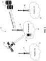
- FIG. 1 schematically illustrates a mobile (cellular) communication system designated generally at 10, in which users of a plurality of mobile communication devices (also referred to herein as user equipments (UEs)) 20 can communicate with other users (not shown) via a suitable cellular radio network such as a UMTS radio access network (UTRAN), or an LTE radio access network (E-UTRAN) and a respective network core in the case of the UTRAN and Evolved Packet Core (EPC) in the case of the E-UTRAN for example.
- UTRAN UMTS radio access network
- E-UTRAN LTE radio access network
- EPC Evolved Packet Core
- the illustrated embodiments may also be used in conjunction with a 5G cellular network.
- the communication system 10 includes a plurality of radio access networks (RAN) 30-34, each including a respective base station 35.
- the base station 35 of a UTRAN radio access network comprises a so called 'NodeB' and the base station 35 of the E-UTRAN radio access network comprises a so called 'eNodeB' (eNodeB).
- the UTRAN base station 35 further includes typically a Radio Network Controller (RNC).
- RNC Radio Network Controller
- the radio network control functionality of the E-UTRAN is integrated typically with the base station functionality in the eNodeB 30.
- the communication system 10 is shown in FIG. 1 to only include three RANs (30-34), however one skilled in the art readily recognizes the communication includes any number of suitable RANs.
- the UE devices 20 of the communication system 10 employ MDT procedures for minimizing drive test requirements in which selected UEs 20 (typically 1-3% of all UEs in the communication system 10) acquire appropriate GPS location measurements and data from a GPS system 40 and report them to the network 10 with, where appropriate, associated location information (e.g., GPS data).
- selected UEs 20 typically 1-3% of all UEs in the communication system 10.
- a communication network monitoring system 50 communicatively coupled to the cellular communication system 10 is a communication network monitoring system 50, such as the TrueCall ® system commercially available from NetScout.
- the network monitoring system is preferably operable and configured to monitor incoming signaling call records from UEs 20 in the communication network 10 to provide enriched and actionable Radio Access Network (RAN) data which may be utilized to diagnose network and UE problems in real-time, understand demand density and usage, support traffic pattern analysis for network capacity planning, geolocate dropped calls, minimize drive testing and gain an end-to-end view from the radio network to the IP Multimedia Subsystem (IMS) core.
- RAN Radio Access Network
- IMS IP Multimedia Subsystem
- the TrueCall ® network monitoring system 50 TrueCall ® provides real-time analysis of data originating in the RANs 30-34.
- the data is enriched using TrueCall's advanced geolocation algorithm, and correlated with subscriber and device data enabling insight into the performance of the RANs 30-34 by combining critical dimensions of a RAN 30 operation in a single location, as further discussed herein.
- Exemplary features and functionality of the TrueCall ® network monitoring system 50 include (but are not limited to): diagnose network and device problems in real-time; identify demand density and drill down to map usage; study traffic patterns; and geolocate calls and minimize drive testing as discussed herein with reference to the described illustrated embodiments.
- a UEs 20 incoming signaling record 55 having radio signal attributes of the UE is received and monitored by the network monitoring system 50.
- Such an incoming signaling call record may include one or more of the following: a Timing Advance (TA) signal; a Minimization of Drive Test (MDT) data record; a signal strength value of a serving eNodeB (cell) 30 for a UE 20 (e.g., a Reference Signal Received Power (RSRP) signal value); a signal quality value of a serving eNodeB (cell) for a UE 20 (e.g., a Reference Signal Received Quality (RSRQ) signal value); a signal strength value of a neighboring cell 32 relative to the serving eNodeB (cell) 30 for a UE 20; and a signal quality value of a neighboring cell 32 relative to the serving eNodeB (cell) 30 for a UE 20.
- TA Timing Advance
- MDT Minimization of Drive Test
- the TA signal value in a cellular communication system 10 corresponds to the length of time a signal takes to reach a base station 35 from a communicating UE mobile phone 20.
- GSM Global System for Mobile
- TDMA Time-division multiple access
- Each user transmits periodically for less than one-eighth of the time within one of the eight timeslots. Since the users are at various distances from the base station and radio waves travel at the finite speed of light, the precise arrival-time within the slot can be used by the base station to determine the distance to the mobile phone.
- Timing Advance is the variable controlling this adjustment. It is to be appreciated that Timing Advance is significant for privacy and communications security, as its combination with other variables can allow GSM localization to find the device's position and track the mobile phone user. TA may also used to adjust transmission power in space-division multiple access systems.
- FIG. 2 is a schematic block diagram of an example computing device 200 used in the network monitoring system 50 that may be used (or components thereof) with one or more embodiments described herein.
- Device 200 is intended to represent any type of computer system capable of carrying out the teachings of various embodiments of the embodiments illustrated herein.
- Device 200 is only one example of a suitable system and is not intended to suggest any limitation as to the scope of use or functionality of embodiments described herein.
- computing device 200 is capable of being implemented and/or performing any of the functionality set forth herein.
- Computing device 200 is operational with numerous other special purpose computing system environments or configurations. Examples of well-known computing systems, environments, and/or configurations that may be suitable for use with computing device 200 include, but are not limited to, personal computer systems, server computer systems, thin clients, thick clients, multiprocessor systems, microprocessor-based systems, and distributed data processing environments that include any of the above systems or devices, and the like.
- Computing device 200 may be described in the general context of computer system-executable instructions, such as program modules, being executed by a computer system.
- program modules may include routines, programs, objects, components, logic, data structures, and so on that perform particular tasks or implement particular abstract data types.
- Computing device 200 may be practiced in distributed data processing environments where tasks are performed by remote processing devices that are linked through a communications network.
- program modules may be located in both local and remote computer system storage media including memory storage devices.
- Device 200 as shown in FIG. 2 may include, but is not limited to, one or more processors or processing units 216, a system memory 228, and a bus 218 that couples various system components including system memory 228 to processor 216.
- Bus 218 represents one or more of any of several types of bus structures, including a memory bus or memory controller, a peripheral bus, an accelerated graphics port, and a processor or local bus using any of a variety of bus architectures.
- bus architectures include Industry Standard Architecture (ISA) bus, Micro Channel Architecture (MCA) bus, Enhanced ISA (EISA) bus, Video Electronics Standards Association (VESA) local bus, and Peripheral Component Interconnect (PCI) bus.
- Computing device 200 typically includes a variety of computer system readable media. Such media may be any available media that is accessible by device 200, and it includes both volatile and non-volatile media, removable and non-removable media.
- System memory 228 can include computer system readable media in the form of volatile memory, such as random access memory (RAM) 230 and/or cache memory 232.
- Computing device 200 may further include other removable/non-removable, volatile/non-volatile computer system storage media.
- storage system 234 can be provided for reading from and writing to a non-removable, non-volatile magnetic media (not shown and typically called a "hard drive").
- a magnetic disk drive for reading from and writing to a removable, non-volatile magnetic disk (e.g., a "floppy disk")
- an optical disk drive for reading from or writing to a removable, non-volatile optical disk such as a CD-ROM, DVD-ROM or other optical media
- each can be connected to bus 218 by one or more data media interfaces.
- memory 228 may include at least one program product having a set (e.g., at least one) of program modules that are configured to carry out the functions of embodiments of the invention.
- Program/utility 240 having a set (at least one) of program modules 215, such as underwriting module, may be stored in memory 228 by way of example, and not limitation, as well as an operating system, one or more application programs, other program modules, and program data. Each of the operating system, one or more application programs, other program modules, and program data or some combination thereof, may include an implementation of a networking environment.
- Program modules 215 generally carry out the functions and/or methodologies of embodiments of the invention as described herein.
- Device 200 may also communicate with one or more external devices 214 such as a keyboard, a pointing device, a display 224, etc.; one or more devices that enable a user to interact with computing device 200; and/or any devices (e.g., network card, modem, etc.) that enable computing device 200 to communicate with one or more other computing devices. Such communication can occur via Input/Output (I/O) interfaces 222. Still yet, device 200 can communicate with one or more networks such as a local area network (LAN), a general wide area network (WAN), a cellular communication system 10 and/or a public network (e.g., the Internet) via network adapter 220. As depicted, network adapter 220 communicates with the other components of computing device 200 via bus 218.
- LAN local area network
- WAN wide area network
- cellular communication system 10 e.g., the Internet
- device 200 includes, but are not limited to: microcode, device drivers, redundant processing units, external disk drive arrays, RAID systems, tape drives, and data archival storage systems, etc.
- FIGS. 1 and 2 are intended to provide a brief, general description of an illustrative and/or suitable exemplary environment in which embodiments of the below described present invention may be implemented.
- FIGS. 1 and 2 are exemplary of a suitable environment and are not intended to suggest any limitation as to the structure, scope of use, or functionality of an illustrated embodiment.
- a particular environment should not be interpreted as having any dependency or requirement relating to any one or combination of components illustrated in an exemplary operating environment. For example, in certain instances, one or more elements of an environment may be deemed not necessary and omitted. In other instances, one or more other elements may be deemed necessary and added.
- geolocation is an important aspect of the diagnostics performed by a network monitoring system 50, which has traditionally been performed using heuristic mathematical models and formulas. It is thus to be appreciated that performing geolocation of UEs using machine learning (MLGL) is a novel technique, which in accordance with the illustrated embodiments preferably uses datasets from Minimize Drive Test (MDT) data so as to leverage certain radio metrics to predict/determine accurate location of the mobile users (UE 20) via machine learning algorithms.
- MDT Minimize Drive Test
- either signal stage or two stage passes of MDT data are utilized to predict/determine the mobile location of a UE 20 in a communication system 10 providing improved accuracy of the determined location.
- ML techniques are typically utilized for analyzing complex and large data sets (e.g., MDT) to understand the underlying relationships, that once understood can be used to do all sorts of application work including prediction for future results.
- MDT complex and large data sets
- ML typically requires research and analysis on a dataset to apply the algorithms in a methodology to reveal correct results.
- MDT data provides "radio signal attributes" along with precise geo-location information.
- MDT data constitutes generally only 1-3% of the monitored traffic in a cellular communication system 10, however, in accordance with the illustrated embodiments, this is nevertheless sufficient to leverage ML algorithms for MLGL.
- radio signal attributes are unique for a cell site (e.g., 30) along with the physical location such as buildings in a downtown area or trees in a rural area, or a combination of later in an urban environment. As to be described below, these attributes are then used in supervised ML algorithms executing on a computing device 200 in the network monitoring system 50 to generate models for each serving cell (e.g., 30) using MDT data.
- a "timing advance (TA) correction model” is created (e.g, TA is adjusted and is called as Machine Learning Timing Advance (MLTA)), which is then processed by a succeeding next "Geo prediction model” along with other radio signal attributes.
- TA timing advance
- MLTA Machine Learning Timing Advance
- These succeeding models are thus utilized to predict the geolocation of a UE 20 in a communication network 10 when MDT data is not present in an incoming signaling record associated with the UE 20, which as noted above is a majority of the time. It is to be appreciated that new MDT data is continuously evaluated by the network monitoring system 50 for UEs 20 present in the communication system 10 such that the aforesaid models are adjusted accordingly.
- new MDT data might reveal changing radio signal attributes due to changed physical attributes such as a new building, tree and/or other obstructions, and thus is continuously integrated into the models.
- a single stage technique is employed utilizing MDT data to predict a location of a UE 20 in a communication system 10.
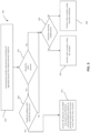
- FIG. 3 shown is a flow chart demonstrating implementation of the ML process 300 for the aforementioned exemplary single and two stage ML embodiments utilizing MDT data to predict a UEs 20 geolocation in a cellular communication system 10 preferably in a network monitoring device 50. It is noted that the order of steps shown in FIG. 3 is not required, so in principle, the various steps may be performed out of the illustrated order. Also certain steps may be skipped, different steps may be added or substituted, or selected steps or groups of steps may be performed in a separate application following the embodiments described herein.
- incoming signaling record from a UE 20 communicatively coupled in the cellular commination network 10 (e.g., an LTE system) which incoming signaling record includes radio signal attributes associated with the UE 20.
- the cellular commination network 10 e.g., an LTE system
- radio signaling attributes may include (and are not to be understood to be limited to): a Timing Advance (TA) signal; a Minimization of Drive Test (MDT) data record; a signal strength value of a serving eNodeB (cell) 30 for a UE 20 (e.g., a Reference Signal Received Power (RSRP) signal value); a signal quality value of a serving eNodeB (cell) for a UE 20 (e.g., a Reference Signal Received Quality (RSRQ) signal value); a signal strength value of a neighboring cell 32 relative to the serving eNodeB (cell) 30 for a UE 20; and a signal quality value of a neighboring cell 32 relative to the serving eNodeB (cell) 30 for a UE 20.
- TA Timing Advance
- MDT Minimization of Drive Test
- a signal strength value of a serving eNodeB (cell) 30 for a UE 20 e.g., a Reference Signal Received Power (
- a threshold range e.g. 1 to 100 meters
- a geolocation machine learning model is generated for determining/predicating a location of future UEs in the cellular communication network 10 by preferably extracting certain ML features and labels from the MDT data record and radio signal attributes from the aforesaid incoming signaling record of the UE 20.
- the illustrated embodiments may utilize machine learning libraries (such as Scikit-leam, pandas, numpy, and other suitable like libraries) for creating the ML models, which are then preferably stored in a ML database. Once stored, the ML models are then retrieved for results predication (e.g., predication/determination of geolocation coordinates).
- this determination includes ensuring the GPS latitude and longitude fields are present with valid ranges (e.g., have not been corrupted); ensuring the MDT accuracy fields are present with an accuracy according to a threshold range (e.g., 1 to 100 meters); and/or ensuring the MDT speed field is present, and preferably with a positive range.
- a threshold range e.g. 1 to 100 meters
- the geo coordinates for the UE 20 are predicted by applying the call/radio signal attributes (e.g., a Timing Advance (TA) signal; a signal strength/quality value of a serving eNodeB (cell) 30 for a UE 20; and a signal strength/quality value of a neighboring cell 32 relative to the serving eNodeB (cell) 30 for a UE 20) and any MDT data records present in the received incoming signaling record for the UE 20 (step 310) to the determined relevant previously generated ML model so as to predict the geo location coordinates for the UE 20 using ML techniques by preferably invoking the prediction functionality of the aforementioned saved ML models.
- the call/radio signal attributes e.g., a Timing Advance (TA) signal; a signal strength/quality value of a serving eNodeB (cell) 30 for a UE 20; and a signal strength/quality value of a neighboring cell 32 relative to the serving eNodeB (cell) 30 for a UE 20
- a corrected TA value for the TA value included in the incoming signaling record for the UE 20 is determined. This is preferably performed by applying the call/radio signal attributes (e.g., a Timing Advance (TA) signal; a signal strength/quality value of a serving eNodeB (cell) 30 for a UE 20; and a signal strength/quality value of a neighboring cell 32 relative to the serving eNodeB (cell) 30 for a UE 20) present in the received incoming signaling record for the UE 20 (step 310) to the determined relevant previously generated ML model so as to predict a corrected TA value for the UE 20 using ML techniques.
- the call/radio signal attributes e.g., a Timing Advance (TA) signal; a signal strength/quality value of a serving eNodeB (cell) 30 for a UE 20; and a signal strength/quality value of a neighboring cell 32 relative to the serving eNodeB (cell) 30 for a UE 20
- the geolocation coordinates for the UE 20 are predicted by applying aforesaid predicted corrected TA value together with other the call/radio signal attributes (e.g., a signal strength/quality value of a serving eNodeB (cell) 30 for a UE 20; and a signal strength/quality value of a neighboring cell 32 relative to the serving eNodeB (cell) 30 for a UE 20) present in the received incoming signaling record for the UE 20 (step 310) to the determined relevant previously generated ML model so as to predict the geolocation location coordinates for the UE 20 using ML techniques by preferably invoking the prediction functionality of the aforementioned saved ML models.
- the call/radio signal attributes e.g., a signal strength/quality value of a serving eNodeB (cell) 30 for a UE 20; and a signal strength/quality value of a neighboring cell 32 relative to the serving eNodeB (cell) 30 for a UE 20
- the geolocation coordinates for the UE is preferably determined utilizing prior known "fixed/ mathematical" methodology using heuristic methods. It is to be appreciated that such utilization of such prior heuristic methods provide decreased accuracy relative to the accuracy of the geolocation coordinates as determined/predicted for the UE 20 in step 335 utilizing the aforementioned ML techniques.
- each cell site 30-34 preferably has unique radio and cell site attributes which over a period of time changes, (e.g., new buildings are constructed or tree growth, thus obstructing the radio signals) thus creating new radio patterns.
- ML machine learning
Landscapes
- Engineering & Computer Science (AREA)
- Computer Networks & Wireless Communication (AREA)
- Signal Processing (AREA)
- Mobile Radio Communication Systems (AREA)
- Position Fixing By Use Of Radio Waves (AREA)
Description
- The disclosed embodiments generally relates to network monitoring devices in communication networks, and more particularly, to using machine learning techniques in network monitoring devices for determining the geolocations of user equipment in cellular communication networks.
- In existing mobile (cellular) communication systems, network operators typically seek to optimize their network coverage based on measurements compiled during so called drive tests. Specifically, an operator can have a technician drive a vehicle around an area covered by the network using specialist equipment to measure performance from a subscriber's perspective. The equipment typically consists of a special test mobile communications device and a wideband scanner, connected to data logging and analysis equipment such as a portable computer. Some drive test equipment is configured for remote operation, thereby allowing equipment to be placed in fleet vehicles (such as taxis, buses, delivery vehicles or the like), for automatic data collection.
- Drive tests typically provide a good source of RF data, in association with related geographic positional information that can be used to identify and resolve coverage problems or the like. However, measurements of a network coverage area can be time consuming, expensive to perform, and often do not accurately represent the experience of a real pedestrian user, such as a user in a building or at a significant distance from a road.
- Accordingly, the 3rd Generation Partnership Project (3 GPP) proposed the development of automated solutions, including the involvement of mobile communication devices (User Equipment (UE)) in the field, in order to minimize operator costs, and the environmental impacts, of network deployment and operation. Studies carried out in response to this proposal demonstrated the feasibility of implementing procedures for minimizing the need for drive tests (referred to herein as 'Minimization of Drive Tests' or '(MDT)' procedures, but also known as `management of UE based network performance measurements'), in which the UE takes measurements for use by the network to improve network optimization and efficiency. More specifically, these studies demonstrated the feasibility of using control plane solutions for acquiring the measurements from devices. This information, together with information available in the radio access network can then be used for coverage optimization purposes.
- Typically, a MDT capable UE is initially configured to perform MDT measurements by the network. On configuration, the MDT capable UE sends detailed user location information including, for example, GPS (Global Positing System) data and/or Radio Frequency fingerprints, along with the reported UE measurements, when requested to do so by the network. This detailed user location information is particularly useful for MDT as it allows an operator to accurately associate the geographical location of the user, within a particular radio cell, with the associated radio measurements; thereby allowing network coverage issues (e.g. coverage holes) to be located accurately.
- It is to be understood that the MDT data reported from UEs may thus be used to monitor and detect different kinds of coverage problems in the network including, for example a coverage hole, which is an area where the signal level of both serving and allowed neighbor cells is below the level needed to maintain basic service. Coverage holes are usually caused by physical obstructions such as new buildings, hills, or by unsuitable antenna parameters, or just inadequate RF planning. In this case, a UE in coverage hole will suffer from a call drop and radio link failure. And another network coverage problem is weak coverage that occurs when the signal level of a serving cell is below the level needed to maintain a planned performance requirement (e.g. the cell edge bit-rate).
- Thus, it is highly desirable that accurate geographical location data be obtained determine the position of these coverage problems, and thereby enable the requisite action to address them.
CN 112 543 470 A discloses background information.
CN 109 996 168 B discloses background information.
WO 2020/234902 A1 discloses background information. - The purpose and advantages of the below described illustrated embodiments will be set forth in and apparent from the description that follows. Additional advantages of the illustrated embodiments will be realized and attained by the devices, systems and methods particularly pointed out in the written description and claims hereof, as well as from the appended drawings.
- The present illustrated embodiments seek to provide an improved communication system, and associated improved network communication devices and methods performed by such devices to provide accurate geographical location data from UEs in a cellular communication system to determine coverage problems in the cellular communication system utilizing acquisition of radio measurements and location information from a UE.
- Aspects of the invention are set out in the appended independent claims. Preferred embodiments are defined in the dependent claims. Any aspects, embodiments and examples of the present disclosure which do not fall under the scope of the appended claims do not form part of the invention and are merely provided for illustrative purposes.
- The accompanying appendices and/or drawings illustrate various non-limiting, example, inventive aspects in accordance with the present disclosure:
-
FIG. 1 illustrates, in simplified overview, a generalized communication system; -
FIG. 2 illustrates an example network monitoring device in the generalized communication system ofFig. 1 ; and -
FIG. 3 illustrates a flow chart depicting a method of operation for a network monitoring device. - The illustrated embodiments are now described more fully with reference to the accompanying drawings wherein like reference numerals identify similar structural/functional features. The illustrated embodiments are not limited in any way to what is illustrated as the illustrated embodiments described below are merely exemplary, which can be embodied in various forms, as appreciated by one skilled in the art. Therefore, it is to be understood that any structural and functional details disclosed herein are not to be interpreted as limiting, but merely as a basis for the claims and as a representation for teaching one skilled in the art to variously employ the discussed embodiments. Furthermore, the terms and phrases used herein are not intended to be limiting but rather to provide an understandable description of the illustrated embodiments.
- Where a range of values is provided, it is understood that each intervening value, to the tenth of the unit of the lower limit unless the context clearly dictates otherwise, between the upper and lower limit of that range and any other stated or intervening value in that stated range is encompassed within the illustrated embodiments. The upper and lower limits of these smaller ranges may independently be included in the smaller ranges is also encompassed within the illustrated embodiments, subject to any specifically excluded limit in the stated range. Where the stated range includes one or both of the limits, ranges excluding either both of those included limits are also included in the illustrated embodiments.
- Unless defined otherwise, all technical and scientific terms used herein have the same meaning as commonly understood by one of ordinary skill in the art to which this invention belongs.
- It must be noted that as used herein and in the appended claims, the singular forms "a", "an," and "the" include plural referents unless the context clearly dictates otherwise. Thus, for example, reference to "a stimulus" includes a plurality of such stimuli and reference to "the signal" includes reference to one or more signals and equivalents thereof known to those skilled in the art, and so forth.
- It is to be appreciated the illustrated embodiments discussed below are preferably a software algorithm, program or code residing on computer useable medium having control logic for enabling execution on a machine having a computer processor. The machine typically includes memory storage configured to provide output from execution of the computer algorithm or program.
- As used herein, the term "software" is meant to be synonymous with any code or program that can be in a processor of a host computer, regardless of whether the implementation is in hardware, firmware or as a software computer product available on a disc, a memory storage device, or for download from a remote machine. The embodiments described herein include such software to implement the equations, relationships and algorithms described above. One skilled in the art will appreciate further features and advantages of the illustrated embodiments based on the above-described embodiments. Accordingly, the illustrated embodiments are not to be limited by what has been particularly shown and described, except as indicated by the appended claims.
-
FIG. 1 schematically illustrates a mobile (cellular) communication system designated generally at 10, in which users of a plurality of mobile communication devices (also referred to herein as user equipments (UEs)) 20 can communicate with other users (not shown) via a suitable cellular radio network such as a UMTS radio access network (UTRAN), or an LTE radio access network (E-UTRAN) and a respective network core in the case of the UTRAN and Evolved Packet Core (EPC) in the case of the E-UTRAN for example. It is also to be appreciated that the illustrated embodiments may also be used in conjunction with a 5G cellular network. - As one skilled in the art would readily recognize, the communication system 10 includes a plurality of radio access networks (RAN) 30-34, each including a
respective base station 35. For instance, thebase station 35 of a UTRAN radio access network comprises a so called 'NodeB' and thebase station 35 of the E-UTRAN radio access network comprises a so called 'eNodeB' (eNodeB). The UTRANbase station 35 further includes typically a Radio Network Controller (RNC). With regard to an E-UTRAN radio access network, the radio network control functionality of the E-UTRAN is integrated typically with the base station functionality in the eNodeB 30. For sake of simplicity the communication system 10 is shown inFIG. 1 to only include three RANs (30-34), however one skilled in the art readily recognizes the communication includes any number of suitable RANs. - It is to be appreciated that the UE
devices 20 of the communication system 10 employ MDT procedures for minimizing drive test requirements in which selected UEs 20 (typically 1-3% of all UEs in the communication system 10) acquire appropriate GPS location measurements and data from aGPS system 40 and report them to the network 10 with, where appropriate, associated location information (e.g., GPS data). - In accordance with the preferred embodiments, communicatively coupled to the cellular communication system 10 is a communication
network monitoring system 50, such as the TrueCall® system commercially available from NetScout. The network monitoring system is preferably operable and configured to monitor incoming signaling call records from UEs 20 in the communication network 10 to provide enriched and actionable Radio Access Network (RAN) data which may be utilized to diagnose network and UE problems in real-time, understand demand density and usage, support traffic pattern analysis for network capacity planning, geolocate dropped calls, minimize drive testing and gain an end-to-end view from the radio network to the IP Multimedia Subsystem (IMS) core. In particular, the TrueCall®network monitoring system 50 TrueCall® provides real-time analysis of data originating in the RANs 30-34. The data is enriched using TrueCall's advanced geolocation algorithm, and correlated with subscriber and device data enabling insight into the performance of the RANs 30-34 by combining critical dimensions of aRAN 30 operation in a single location, as further discussed herein. Exemplary features and functionality of the TrueCall®network monitoring system 50 include (but are not limited to): diagnose network and device problems in real-time; identify demand density and drill down to map usage; study traffic patterns; and geolocate calls and minimize drive testing as discussed herein with reference to the described illustrated embodiments. - It is to be appreciated that a
UEs 20 incoming signaling record 55 having radio signal attributes of the UE is received and monitored by thenetwork monitoring system 50. Such an incoming signaling call record may include one or more of the following: a Timing Advance (TA) signal; a Minimization of Drive Test (MDT) data record; a signal strength value of a serving eNodeB (cell) 30 for a UE 20 (e.g., a Reference Signal Received Power (RSRP) signal value); a signal quality value of a serving eNodeB (cell) for a UE 20 (e.g., a Reference Signal Received Quality (RSRQ) signal value); a signal strength value of a neighboringcell 32 relative to the serving eNodeB (cell) 30 for aUE 20; and a signal quality value of a neighboringcell 32 relative to the serving eNodeB (cell) 30 for aUE 20. - It is to be understood the TA signal value in a cellular communication system 10 corresponds to the length of time a signal takes to reach a
base station 35 from a communicating UEmobile phone 20. For instance, a Global System for Mobile (GSM) uses Time-division multiple access (TDMA) technology in the radio interface to share a single frequency between several users, assigning sequential timeslots to the individual users sharing a frequency. Each user transmits periodically for less than one-eighth of the time within one of the eight timeslots. Since the users are at various distances from the base station and radio waves travel at the finite speed of light, the precise arrival-time within the slot can be used by the base station to determine the distance to the mobile phone. The time at which the phone is allowed to transmit a burst of traffic within a timeslot must be adjusted accordingly to prevent collisions with adjacent users. Timing Advance (TA) is the variable controlling this adjustment. It is to be appreciated that Timing Advance is significant for privacy and communications security, as its combination with other variables can allow GSM localization to find the device's position and track the mobile phone user. TA may also used to adjust transmission power in space-division multiple access systems. - With regard to the
network monitoring system 50,FIG. 2 is a schematic block diagram of anexample computing device 200 used in thenetwork monitoring system 50 that may be used (or components thereof) with one or more embodiments described herein.Device 200 is intended to represent any type of computer system capable of carrying out the teachings of various embodiments of the embodiments illustrated herein.Device 200 is only one example of a suitable system and is not intended to suggest any limitation as to the scope of use or functionality of embodiments described herein. Regardless,computing device 200 is capable of being implemented and/or performing any of the functionality set forth herein. -
Computing device 200 is operational with numerous other special purpose computing system environments or configurations. Examples of well-known computing systems, environments, and/or configurations that may be suitable for use withcomputing device 200 include, but are not limited to, personal computer systems, server computer systems, thin clients, thick clients, multiprocessor systems, microprocessor-based systems, and distributed data processing environments that include any of the above systems or devices, and the like. -
Computing device 200 may be described in the general context of computer system-executable instructions, such as program modules, being executed by a computer system. Generally, program modules may include routines, programs, objects, components, logic, data structures, and so on that perform particular tasks or implement particular abstract data types.Computing device 200 may be practiced in distributed data processing environments where tasks are performed by remote processing devices that are linked through a communications network. In a distributed data processing environment, program modules may be located in both local and remote computer system storage media including memory storage devices. -
Device 200 as shown inFIG. 2 may include, but is not limited to, one or more processors orprocessing units 216, asystem memory 228, and abus 218 that couples various system components includingsystem memory 228 toprocessor 216. -
Bus 218 represents one or more of any of several types of bus structures, including a memory bus or memory controller, a peripheral bus, an accelerated graphics port, and a processor or local bus using any of a variety of bus architectures. By way of example, and not limitation, such architectures include Industry Standard Architecture (ISA) bus, Micro Channel Architecture (MCA) bus, Enhanced ISA (EISA) bus, Video Electronics Standards Association (VESA) local bus, and Peripheral Component Interconnect (PCI) bus. -
Computing device 200 typically includes a variety of computer system readable media. Such media may be any available media that is accessible bydevice 200, and it includes both volatile and non-volatile media, removable and non-removable media. -
System memory 228 can include computer system readable media in the form of volatile memory, such as random access memory (RAM) 230 and/orcache memory 232.Computing device 200 may further include other removable/non-removable, volatile/non-volatile computer system storage media. By way of example only,storage system 234 can be provided for reading from and writing to a non-removable, non-volatile magnetic media (not shown and typically called a "hard drive"). Although not shown, a magnetic disk drive for reading from and writing to a removable, non-volatile magnetic disk (e.g., a "floppy disk"), and an optical disk drive for reading from or writing to a removable, non-volatile optical disk such as a CD-ROM, DVD-ROM or other optical media can be provided. In such instances, each can be connected tobus 218 by one or more data media interfaces. As will be further depicted and described below,memory 228 may include at least one program product having a set (e.g., at least one) of program modules that are configured to carry out the functions of embodiments of the invention. - Program/
utility 240, having a set (at least one) ofprogram modules 215, such as underwriting module, may be stored inmemory 228 by way of example, and not limitation, as well as an operating system, one or more application programs, other program modules, and program data. Each of the operating system, one or more application programs, other program modules, and program data or some combination thereof, may include an implementation of a networking environment.Program modules 215 generally carry out the functions and/or methodologies of embodiments of the invention as described herein. -
Device 200 may also communicate with one or moreexternal devices 214 such as a keyboard, a pointing device, adisplay 224, etc.; one or more devices that enable a user to interact withcomputing device 200; and/or any devices (e.g., network card, modem, etc.) that enablecomputing device 200 to communicate with one or more other computing devices. Such communication can occur via Input/Output (I/O) interfaces 222. Still yet,device 200 can communicate with one or more networks such as a local area network (LAN), a general wide area network (WAN), a cellular communication system 10 and/or a public network (e.g., the Internet) vianetwork adapter 220. As depicted,network adapter 220 communicates with the other components ofcomputing device 200 viabus 218. It should be understood that although not shown, other hardware and/or software components could be used in conjunction withdevice 200. Examples, include, but are not limited to: microcode, device drivers, redundant processing units, external disk drive arrays, RAID systems, tape drives, and data archival storage systems, etc. -
FIGS. 1 and2 are intended to provide a brief, general description of an illustrative and/or suitable exemplary environment in which embodiments of the below described present invention may be implemented.FIGS. 1 and2 are exemplary of a suitable environment and are not intended to suggest any limitation as to the structure, scope of use, or functionality of an illustrated embodiment. A particular environment should not be interpreted as having any dependency or requirement relating to any one or combination of components illustrated in an exemplary operating environment. For example, in certain instances, one or more elements of an environment may be deemed not necessary and omitted. In other instances, one or more other elements may be deemed necessary and added. - With the exemplary cellular communication network 10 (
FIG. 1 ) and computing device 200 (FIG. 2 ) being generally shown and discussed above, description of certain illustrated embodiments will now be provided. In understanding and appreciating the illustrated embodiments, it is to be understood geolocation (GL) is an important aspect of the diagnostics performed by anetwork monitoring system 50, which has traditionally been performed using heuristic mathematical models and formulas. It is thus to be appreciated that performing geolocation of UEs using machine learning (MLGL) is a novel technique, which in accordance with the illustrated embodiments preferably uses datasets from Minimize Drive Test (MDT) data so as to leverage certain radio metrics to predict/determine accurate location of the mobile users (UE 20) via machine learning algorithms. As demonstrated herein, this approach produces improved accurate results compared to prior heuristic mathematical techniques. As described in accordance with the embodiments illustrated herein, either signal stage or two stage passes of MDT data are utilized to predict/determine the mobile location of aUE 20 in a communication system 10 providing improved accuracy of the determined location. - It is to be appreciated that ML techniques are typically utilized for analyzing complex and large data sets (e.g., MDT) to understand the underlying relationships, that once understood can be used to do all sorts of application work including prediction for future results. As one skilled in the art appreciates, ML typically requires research and analysis on a dataset to apply the algorithms in a methodology to reveal correct results.
- In particular, it is to be appreciated and understood that MDT data provides "radio signal attributes" along with precise geo-location information. However, such MDT data constitutes generally only 1-3% of the monitored traffic in a cellular communication system 10, however, in accordance with the illustrated embodiments, this is nevertheless sufficient to leverage ML algorithms for MLGL. It is noted radio signal attributes are unique for a cell site (e.g., 30) along with the physical location such as buildings in a downtown area or trees in a rural area, or a combination of later in an urban environment. As to be described below, these attributes are then used in supervised ML algorithms executing on a
computing device 200 in thenetwork monitoring system 50 to generate models for each serving cell (e.g., 30) using MDT data. - In accordance with an illustrated embodiment, in a two stage technique, a "timing advance (TA) correction model" is created (e.g, TA is adjusted and is called as Machine Learning Timing Advance (MLTA)), which is then processed by a succeeding next "Geo prediction model" along with other radio signal attributes. These succeeding models are thus utilized to predict the geolocation of a
UE 20 in a communication network 10 when MDT data is not present in an incoming signaling record associated with theUE 20, which as noted above is a majority of the time. It is to be appreciated that new MDT data is continuously evaluated by thenetwork monitoring system 50 forUEs 20 present in the communication system 10 such that the aforesaid models are adjusted accordingly. For instance, new MDT data might reveal changing radio signal attributes due to changed physical attributes such as a new building, tree and/or other obstructions, and thus is continuously integrated into the models. Additionally, in accordance with another illustrated embodiment, and as also described below, a single stage technique is employed utilizing MDT data to predict a location of aUE 20 in a communication system 10. - With reference now to
FIG. 3 , shown is a flow chart demonstrating implementation of theML process 300 for the aforementioned exemplary single and two stage ML embodiments utilizing MDT data to predict aUEs 20 geolocation in a cellular communication system 10 preferably in anetwork monitoring device 50. It is noted that the order of steps shown inFIG. 3 is not required, so in principle, the various steps may be performed out of the illustrated order. Also certain steps may be skipped, different steps may be added or substituted, or selected steps or groups of steps may be performed in a separate application following the embodiments described herein. - Starting at
step 310, received and monitored preferably in thenetwork monitoring system 50 is an incoming signaling record from aUE 20 communicatively coupled in the cellular commination network 10 (e.g., an LTE system) which incoming signaling record includes radio signal attributes associated with theUE 20. As mentioned above, such radio signaling attributes may include (and are not to be understood to be limited to): a Timing Advance (TA) signal; a Minimization of Drive Test (MDT) data record; a signal strength value of a serving eNodeB (cell) 30 for a UE 20 (e.g., a Reference Signal Received Power (RSRP) signal value); a signal quality value of a serving eNodeB (cell) for a UE 20 (e.g., a Reference Signal Received Quality (RSRQ) signal value); a signal strength value of a neighboringcell 32 relative to the serving eNodeB (cell) 30 for aUE 20; and a signal quality value of a neighboringcell 32 relative to the serving eNodeB (cell) 30 for aUE 20. - Next, at step 315 a determination is preferably made as to whether the aforesaid incoming signaling record includes MDT data records. If it is determined MDT data records are included in the received incoming signaling record of the
UE 20, then atstep 320 the MDT data records are preferably verified and validated for GPS accuracy. This preferably includes: ensuring the GPS latitude and longitude fields are present with valid ranges (e.g., have not been corrupted); ensuring the MDT accuracy fields are present with an accuracy according to a threshold range (e.g., 1 to 100 meters); and/or ensuring the MDT speed field is present, and preferably with a positive range. If the MDT data records are verified/validated instep 320, then in step 325 a geolocation machine learning model is generated for determining/predicating a location of future UEs in the cellular communication network 10 by preferably extracting certain ML features and labels from the MDT data record and radio signal attributes from the aforesaid incoming signaling record of theUE 20. For instance, the illustrated embodiments may utilize machine learning libraries (such as Scikit-leam, pandas, numpy, and other suitable like libraries) for creating the ML models, which are then preferably stored in a ML database. Once stored, the ML models are then retrieved for results predication (e.g., predication/determination of geolocation coordinates). And in the event a ML model was previously created for the aforesaid MDT data record and radio signal attributes from the aforesaid incoming signaling record of theUE 20 attributable to a given cell (30-34), then such an existing ML updated with the new records (e.g., MDT data record and radio signal attributes from the aforesaid incoming signaling record of the UE 20) for a given cell (30-34). - If at
step 315 MDT data records were not determined present in the incoming signaling record of theUE 20, or if atstep 320 the MDT data records could not be verified/validated, then at step 330 a determination is preferably made as to whether a ML model (as previously generated in step 325) exists that is determined relevant for the signal attributes contained in the incoming signaling record for theUE 20 for determining/predicting the geolocation of theUE 20 using ML techniques utilizing ML models previously generated instep 325. For instance, this determination includes ensuring the GPS latitude and longitude fields are present with valid ranges (e.g., have not been corrupted); ensuring the MDT accuracy fields are present with an accuracy according to a threshold range (e.g., 1 to 100 meters); and/or ensuring the MDT speed field is present, and preferably with a positive range. - If at
step 330 it is determined that one or more ML model exists determined relevant for the signal attributes contained in the incoming signaling record for theUE 20, then in accordance with a single stage process the geo coordinates for theUE 20 are predicted by applying the call/radio signal attributes (e.g., a Timing Advance (TA) signal; a signal strength/quality value of a serving eNodeB (cell) 30 for aUE 20; and a signal strength/quality value of a neighboringcell 32 relative to the serving eNodeB (cell) 30 for a UE 20) and any MDT data records present in the received incoming signaling record for the UE 20 (step 310) to the determined relevant previously generated ML model so as to predict the geo location coordinates for theUE 20 using ML techniques by preferably invoking the prediction functionality of the aforementioned saved ML models. - And in accordance with the aforementioned two stage process, first a corrected TA value for the TA value included in the incoming signaling record for the
UE 20 is determined. This is preferably performed by applying the call/radio signal attributes (e.g., a Timing Advance (TA) signal; a signal strength/quality value of a serving eNodeB (cell) 30 for aUE 20; and a signal strength/quality value of a neighboringcell 32 relative to the serving eNodeB (cell) 30 for a UE 20) present in the received incoming signaling record for the UE 20 (step 310) to the determined relevant previously generated ML model so as to predict a corrected TA value for theUE 20 using ML techniques. After the corrected TA value for theUE 20 using ML techniques is predicted, then in a second succeeding stage the geolocation coordinates for theUE 20 are predicted by applying aforesaid predicted corrected TA value together with other the call/radio signal attributes (e.g., a signal strength/quality value of a serving eNodeB (cell) 30 for aUE 20; and a signal strength/quality value of a neighboringcell 32 relative to the serving eNodeB (cell) 30 for a UE 20) present in the received incoming signaling record for the UE 20 (step 310) to the determined relevant previously generated ML model so as to predict the geolocation location coordinates for theUE 20 using ML techniques by preferably invoking the prediction functionality of the aforementioned saved ML models. - And if at
step 330 it was determined that one or more ML models did not exist determined relevant for the signal attributes contained in the incoming signaling record for theUE 20, then atstep 340 the geolocation coordinates for the UE is preferably determined utilizing prior known "fixed/ mathematical" methodology using heuristic methods. It is to be appreciated that such utilization of such prior heuristic methods provide decreased accuracy relative to the accuracy of the geolocation coordinates as determined/predicted for theUE 20 instep 335 utilizing the aforementioned ML techniques. - With certain illustrated embodiments described above, it is to be appreciated that various non-limiting embodiments described herein may be used separately, combined or selectively combined for specific applications. Further, some of the various features of the above non-limiting embodiments may be used without the corresponding use of other described features. The foregoing description should therefore be considered as merely illustrative of the principles, teachings and exemplary embodiments of this invention, and not in limitation thereof.
- Thus, it is to be appreciated that what has been described above is determining geolocation coordinates using machine learning (ML) techniques, which is in contrast to the prior "fixed/ mathematical" methodology using heuristic methods, wherein the ML approach is adaptable to each cell site 30-34. In other words, each cell site 30-34 preferably has unique radio and cell site attributes which over a period of time changes, (e.g., new buildings are constructed or tree growth, thus obstructing the radio signals) thus creating new radio patterns. This results in changed MDT data, however the models for each cell 30-34 are also adapted in real time, which was not possible with the prior known "fixed/ mathematical" methodology using heuristic methods.
- Although the invention has been explained in relation to its preferred embodiment(s) as mentioned above, it is to be understood that many other possible modifications and variations can be made without departing from the scope of the present invention, which is defined by the claims.
Claims (15)
- A machine learning method (300) performed by a communication network monitoring device (50), the method comprising:receiving an incoming signaling record having radio signal attributes from a user equipment (20), UE (20), in a cellular communication network;determining whether the UE incoming signaling record includes Global Positioning Signaling, GPS, data; andrespectively, either:responsive to determining that the UE incoming signaling record includes the GPS data, training a machine learning model by using the radio signal attributes and the GPS data, the machine learning model for determining a location of future UE (20) in the communication network; orresponsive to determining that the GPS data is not included in the UE incoming signaling record, determining a geolocation for the UE (20) by applying at least the radio signal attributes to a previously trained machine learning model;wherein the radio signal attributes include a Timing Advance, TA, value; andwherein, responsive to determining that the UE incoming signaling record does not include the GPS data, the method further comprises:determining a corrected TA value for the TA value included in the incoming signaling record by applying the radio signal attributes included in the UE incoming signalling record to the previously trained machine learning model; anddetermining the geolocation for the UE (20) by further applying the corrected TA value to the previously trained machine learning model.
- The method of claim 1, further comprising:determining that the previously trained machine learning model is relevant for the radio signal attributes for the UE incoming signaling record; andresponsive to determining that the previously trained machine learning model is relevant for the radio signal attributes for the UE incoming signaling record, determining the geolocation for the UE (20) by applying at least the radio signal attributes to the previously trained machine learning model.
- The method of claim 1, further comprising:determining that the previously trained machine learning model is relevant for the radio signal attributes for the UE incoming signaling record; andresponsive to determining that the previously trained machine learning model is relevant for the radio signal attributes for the UE incoming signaling record:determining the corrected TA value for the TA value included in the incoming signaling record; anddetermining the geolocation for the UE (20) by further applying the corrected TA value to the previously trained machine learning model.
- The method of claim 1, wherein determining if the UE incoming signaling record includes the GPS data includes:determining (315) whether the UE incoming signaling record includes a Minimization of Drive Test, MDT, data record;validating (320) a location accuracy of the MDT data record; andresponsive to validating the location accuracy of the MDT, training the machine learning model.
- The method of claim 4, wherein the GPS data and radio signal attributes are embodied in the MDT data record.
- The method of claim 4, wherein the radio signal attributes include a Reference Signal Received Power, RSRP, signal value of a serving base station for the UE (20).
- The method of claim 4, wherein the radio signal attributes include a Reference Signal Received Quality, RSRQ, signal value of a serving base station for the UE (20).
- The method of claim 4, wherein the radio signal attributes include a Reference Signal Received Power, RSRP, signal value of a neighboring base station relative to a serving base station.
- The method of claim 4, wherein the radio signal attributes include a Reference Signal Received Quality, RSRQ, signal value of a neighboring base station relative to a serving base station.
- A communication network monitoring device (50), comprising:a memory (228) comprising instructions; anda processor (216) in communication with the memory (228), wherein the instructions, upon execution by the processor (216), cause the processor (216) to perform the method according to claim 1.
- The device of claim 10, wherein the instructions, upon execution by the processor (216), further cause the processor (216) to:determine that the previously trained machine learning model is relevant for the radio signal attributes for the UE incoming signaling record; andresponsive to determining that the previously trained machine learning model is relevant for the radio signal attributes for the UE incoming signaling record, determine the geolocation for the UE (20) by applying at least the radio signal attributes to the previously trained machine learning model.
- The device of claim 10, wherein the instructions, upon execution by the processor (216), further cause the processor (216) to:determine that the previously trained machine learning model is relevant for the radio signal attributes for the UE incoming signaling record; andresponsive to determining that the previously trained machine learning model is relevant for the radio signal attributes for the UE incoming signaling record:determine the corrected TA value for the TA value included in the incoming signaling record; anddetermine the geolocation for the UE (20) by further applying the corrected TA value to the previously trained machine learning model.
- The device of claim 10, wherein the instructions, upon execution by the processor (216), further cause the processor (216) to:determine (315) whether the UE incoming signaling record includes a Minimization of Drive Test, MDT, data record;validate (320) a location accuracy of the MDT data record; andresponsive to validating the location accuracy of the MDT, train the machine learning model.
- The device of claim 13, wherein the GPS data and radio signal attributes are embodied in the MDT data record.
- The device of claim 13, wherein the radio signal attributes include a Reference Signal Received Power, RSRP, signal value of a serving base station; and/or
wherein the radio signal attributes include a Reference Signal Received Quality, RSRQ, signal value of a serving base station.
Applications Claiming Priority (3)
| Application Number | Priority Date | Filing Date | Title |
|---|---|---|---|
| US17/401,059 US11743856B2 (en) | 2021-08-12 | 2021-08-12 | Determining geolocation of devices in a communication network |
| US17/401,070 US11758351B2 (en) | 2021-08-12 | 2021-08-12 | Determining geolocation of devices in a communication network |
| PCT/US2022/040171 WO2023018943A1 (en) | 2021-08-12 | 2022-08-12 | Determining geolocation of devices in a communication network |
Publications (2)
| Publication Number | Publication Date |
|---|---|
| EP4385235A1 EP4385235A1 (en) | 2024-06-19 |
| EP4385235B1 true EP4385235B1 (en) | 2024-12-04 |
Family
ID=83506032
Family Applications (1)
| Application Number | Title | Priority Date | Filing Date |
|---|---|---|---|
| EP22778096.2A Active EP4385235B1 (en) | 2021-08-12 | 2022-08-12 | Determining geolocation of devices in a communication network |
Country Status (4)
| Country | Link |
|---|---|
| EP (1) | EP4385235B1 (en) |
| AU (1) | AU2022327109B2 (en) |
| CA (1) | CA3229094A1 (en) |
| WO (1) | WO2023018943A1 (en) |
Families Citing this family (1)
| Publication number | Priority date | Publication date | Assignee | Title |
|---|---|---|---|---|
| US12445990B2 (en) | 2022-10-21 | 2025-10-14 | Qualcomm Incorporated | Machine learning based timing advance updates |
Family Cites Families (3)
| Publication number | Priority date | Publication date | Assignee | Title |
|---|---|---|---|---|
| CN109996168B (en) * | 2017-12-28 | 2020-11-20 | 中国移动通信集团吉林有限公司 | A method and device for obtaining terminal position |
| KR102654497B1 (en) * | 2019-05-20 | 2024-04-03 | 사안크야 랩스 프라이빗 리미티드 | RADIO MAPPING ARCHITECTURE FOR APPLYING MACHINE LEARNING TECHNIQUES TO WIRELESS RADIO ACCESS NETWORKS |
| CN112543470B (en) * | 2019-09-23 | 2023-04-07 | 中国移动通信集团重庆有限公司 | Terminal positioning method and system based on machine learning |
-
2022
- 2022-08-12 WO PCT/US2022/040171 patent/WO2023018943A1/en not_active Ceased
- 2022-08-12 CA CA3229094A patent/CA3229094A1/en active Pending
- 2022-08-12 AU AU2022327109A patent/AU2022327109B2/en active Active
- 2022-08-12 EP EP22778096.2A patent/EP4385235B1/en active Active
Also Published As
| Publication number | Publication date |
|---|---|
| AU2022327109A1 (en) | 2024-03-07 |
| EP4385235A1 (en) | 2024-06-19 |
| CA3229094A1 (en) | 2023-02-16 |
| WO2023018943A1 (en) | 2023-02-16 |
| AU2022327109B2 (en) | 2024-11-07 |
Similar Documents
| Publication | Publication Date | Title |
|---|---|---|
| US10542519B2 (en) | Terminal positioning method and network device | |
| US6442384B1 (en) | System and method for identification of uplink/downlink interference sources | |
| EP1662827A1 (en) | Apparatus and method for geostatistical analysis of wireless signal propagation | |
| CN110392379B (en) | Method and device for positioning network problem, electronic equipment and storage medium | |
| CN108307427B (en) | LTE network coverage analysis and prediction method and system | |
| US10382883B2 (en) | Automatic calibration of geolocation analytic systems and operator network equipment parameters | |
| US12593298B2 (en) | Method of estimating a geographic location of a mobile device | |
| EP2018592B1 (en) | System and method for detecting locations of a customer premises equipment | |
| CN1514552A (en) | A method for simulating the operating environment of a telecommunications system requiring limited computation | |
| CN103458434B (en) | Method and device for determining antenna feeder parameters | |
| CN108259097B (en) | Method and device for correcting wireless propagation model based on MR data | |
| US11991661B2 (en) | Determining geolocation of devices in a communication network | |
| AU2022327109B2 (en) | Determining geolocation of devices in a communication network | |
| CN114745289A (en) | Method, device, storage medium and equipment for predicting network performance data | |
| US11758351B2 (en) | Determining geolocation of devices in a communication network | |
| CN115278527A (en) | Mobile signal equipment configuration method and device, electronic equipment and storage medium | |
| US20170254878A1 (en) | Position Adjustment in Mobile Communications Networks | |
| CN113840225B (en) | Terminal positioning method, device and storage medium | |
| WO2002032164A2 (en) | A system and method for applying reciprocity for downlink interference identification | |
| CN115038040B (en) | Cell positioning method, device, equipment, system and medium | |
| KR100673201B1 (en) | Radio environment analysis system and method | |
| Zhang et al. | M2M facilitated wireless network coverage management and real-time monitoring | |
| CN119893660A (en) | Positioning method, device and system | |
| CN103874194A (en) | Auxiliary triangle positioning device and method for the same based on user behavior simulation | |
| CN116938736A (en) | Outdoor distribution cell analysis method, device, electronic equipment and program product |
Legal Events
| Date | Code | Title | Description |
|---|---|---|---|
| STAA | Information on the status of an ep patent application or granted ep patent |
Free format text: STATUS: UNKNOWN |
|
| STAA | Information on the status of an ep patent application or granted ep patent |
Free format text: STATUS: THE INTERNATIONAL PUBLICATION HAS BEEN MADE |
|
| PUAI | Public reference made under article 153(3) epc to a published international application that has entered the european phase |
Free format text: ORIGINAL CODE: 0009012 |
|
| STAA | Information on the status of an ep patent application or granted ep patent |
Free format text: STATUS: REQUEST FOR EXAMINATION WAS MADE |
|
| 17P | Request for examination filed |
Effective date: 20240212 |
|
| AK | Designated contracting states |
Kind code of ref document: A1 Designated state(s): AL AT BE BG CH CY CZ DE DK EE ES FI FR GB GR HR HU IE IS IT LI LT LU LV MC MK MT NL NO PL PT RO RS SE SI SK SM TR |
|
| GRAP | Despatch of communication of intention to grant a patent |
Free format text: ORIGINAL CODE: EPIDOSNIGR1 |
|
| STAA | Information on the status of an ep patent application or granted ep patent |
Free format text: STATUS: GRANT OF PATENT IS INTENDED |
|
| RIC1 | Information provided on ipc code assigned before grant |
Ipc: H04W 56/00 20090101ALI20240715BHEP Ipc: H04W 64/00 20090101ALI20240715BHEP Ipc: H04W 24/00 20090101AFI20240715BHEP |
|
| GRAS | Grant fee paid |
Free format text: ORIGINAL CODE: EPIDOSNIGR3 |
|
| DAV | Request for validation of the european patent (deleted) | ||
| DAX | Request for extension of the european patent (deleted) | ||
| INTG | Intention to grant announced |
Effective date: 20240812 |
|
| P01 | Opt-out of the competence of the unified patent court (upc) registered |
Free format text: CASE NUMBER: APP_47687/2024 Effective date: 20240819 |
|
| GRAA | (expected) grant |
Free format text: ORIGINAL CODE: 0009210 |
|
| STAA | Information on the status of an ep patent application or granted ep patent |
Free format text: STATUS: THE PATENT HAS BEEN GRANTED |
|
| AK | Designated contracting states |
Kind code of ref document: B1 Designated state(s): AL AT BE BG CH CY CZ DE DK EE ES FI FR GB GR HR HU IE IS IT LI LT LU LV MC MK MT NL NO PL PT RO RS SE SI SK SM TR |
|
| REG | Reference to a national code |
Ref country code: CH Ref legal event code: EP |
|
| REG | Reference to a national code |
Ref country code: DE Ref legal event code: R096 Ref document number: 602022008471 Country of ref document: DE |
|
| REG | Reference to a national code |
Ref country code: IE Ref legal event code: FG4D |
|
| REG | Reference to a national code |
Ref country code: LT Ref legal event code: MG9D |
|
| REG | Reference to a national code |
Ref country code: NL Ref legal event code: MP Effective date: 20241204 |
|
| PG25 | Lapsed in a contracting state [announced via postgrant information from national office to epo] |
Ref country code: HR Free format text: LAPSE BECAUSE OF FAILURE TO SUBMIT A TRANSLATION OF THE DESCRIPTION OR TO PAY THE FEE WITHIN THE PRESCRIBED TIME-LIMIT Effective date: 20241204 |
|
| PG25 | Lapsed in a contracting state [announced via postgrant information from national office to epo] |
Ref country code: FI Free format text: LAPSE BECAUSE OF FAILURE TO SUBMIT A TRANSLATION OF THE DESCRIPTION OR TO PAY THE FEE WITHIN THE PRESCRIBED TIME-LIMIT Effective date: 20241204 |
|
| PG25 | Lapsed in a contracting state [announced via postgrant information from national office to epo] |
Ref country code: BG Free format text: LAPSE BECAUSE OF FAILURE TO SUBMIT A TRANSLATION OF THE DESCRIPTION OR TO PAY THE FEE WITHIN THE PRESCRIBED TIME-LIMIT Effective date: 20241204 |
|
| PG25 | Lapsed in a contracting state [announced via postgrant information from national office to epo] |
Ref country code: ES Free format text: LAPSE BECAUSE OF FAILURE TO SUBMIT A TRANSLATION OF THE DESCRIPTION OR TO PAY THE FEE WITHIN THE PRESCRIBED TIME-LIMIT Effective date: 20241204 |
|
| PG25 | Lapsed in a contracting state [announced via postgrant information from national office to epo] |
Ref country code: NO Free format text: LAPSE BECAUSE OF FAILURE TO SUBMIT A TRANSLATION OF THE DESCRIPTION OR TO PAY THE FEE WITHIN THE PRESCRIBED TIME-LIMIT Effective date: 20250304 |
|
| PG25 | Lapsed in a contracting state [announced via postgrant information from national office to epo] |
Ref country code: GR Free format text: LAPSE BECAUSE OF FAILURE TO SUBMIT A TRANSLATION OF THE DESCRIPTION OR TO PAY THE FEE WITHIN THE PRESCRIBED TIME-LIMIT Effective date: 20250305 Ref country code: LV Free format text: LAPSE BECAUSE OF FAILURE TO SUBMIT A TRANSLATION OF THE DESCRIPTION OR TO PAY THE FEE WITHIN THE PRESCRIBED TIME-LIMIT Effective date: 20241204 |
|
| PG25 | Lapsed in a contracting state [announced via postgrant information from national office to epo] |
Ref country code: RS Free format text: LAPSE BECAUSE OF FAILURE TO SUBMIT A TRANSLATION OF THE DESCRIPTION OR TO PAY THE FEE WITHIN THE PRESCRIBED TIME-LIMIT Effective date: 20250304 |
|
| PG25 | Lapsed in a contracting state [announced via postgrant information from national office to epo] |
Ref country code: NL Free format text: LAPSE BECAUSE OF FAILURE TO SUBMIT A TRANSLATION OF THE DESCRIPTION OR TO PAY THE FEE WITHIN THE PRESCRIBED TIME-LIMIT Effective date: 20241204 |
|
| REG | Reference to a national code |
Ref country code: AT Ref legal event code: MK05 Ref document number: 1749455 Country of ref document: AT Kind code of ref document: T Effective date: 20241204 |
|
| PG25 | Lapsed in a contracting state [announced via postgrant information from national office to epo] |
Ref country code: SM Free format text: LAPSE BECAUSE OF FAILURE TO SUBMIT A TRANSLATION OF THE DESCRIPTION OR TO PAY THE FEE WITHIN THE PRESCRIBED TIME-LIMIT Effective date: 20241204 |
|
| PG25 | Lapsed in a contracting state [announced via postgrant information from national office to epo] |
Ref country code: PL Free format text: LAPSE BECAUSE OF FAILURE TO SUBMIT A TRANSLATION OF THE DESCRIPTION OR TO PAY THE FEE WITHIN THE PRESCRIBED TIME-LIMIT Effective date: 20241204 |
|
| PG25 | Lapsed in a contracting state [announced via postgrant information from national office to epo] |
Ref country code: IS Free format text: LAPSE BECAUSE OF FAILURE TO SUBMIT A TRANSLATION OF THE DESCRIPTION OR TO PAY THE FEE WITHIN THE PRESCRIBED TIME-LIMIT Effective date: 20250404 |
|
| PG25 | Lapsed in a contracting state [announced via postgrant information from national office to epo] |
Ref country code: PT Free format text: LAPSE BECAUSE OF FAILURE TO SUBMIT A TRANSLATION OF THE DESCRIPTION OR TO PAY THE FEE WITHIN THE PRESCRIBED TIME-LIMIT Effective date: 20250404 |
|
| PG25 | Lapsed in a contracting state [announced via postgrant information from national office to epo] |
Ref country code: EE Free format text: LAPSE BECAUSE OF FAILURE TO SUBMIT A TRANSLATION OF THE DESCRIPTION OR TO PAY THE FEE WITHIN THE PRESCRIBED TIME-LIMIT Effective date: 20241204 |
|
| PG25 | Lapsed in a contracting state [announced via postgrant information from national office to epo] |
Ref country code: AT Free format text: LAPSE BECAUSE OF FAILURE TO SUBMIT A TRANSLATION OF THE DESCRIPTION OR TO PAY THE FEE WITHIN THE PRESCRIBED TIME-LIMIT Effective date: 20241204 Ref country code: RO Free format text: LAPSE BECAUSE OF FAILURE TO SUBMIT A TRANSLATION OF THE DESCRIPTION OR TO PAY THE FEE WITHIN THE PRESCRIBED TIME-LIMIT Effective date: 20241204 |
|
| PG25 | Lapsed in a contracting state [announced via postgrant information from national office to epo] |
Ref country code: SK Free format text: LAPSE BECAUSE OF FAILURE TO SUBMIT A TRANSLATION OF THE DESCRIPTION OR TO PAY THE FEE WITHIN THE PRESCRIBED TIME-LIMIT Effective date: 20241204 |
|
| PG25 | Lapsed in a contracting state [announced via postgrant information from national office to epo] |
Ref country code: CZ Free format text: LAPSE BECAUSE OF FAILURE TO SUBMIT A TRANSLATION OF THE DESCRIPTION OR TO PAY THE FEE WITHIN THE PRESCRIBED TIME-LIMIT Effective date: 20241204 |
|
| PG25 | Lapsed in a contracting state [announced via postgrant information from national office to epo] |
Ref country code: IT Free format text: LAPSE BECAUSE OF FAILURE TO SUBMIT A TRANSLATION OF THE DESCRIPTION OR TO PAY THE FEE WITHIN THE PRESCRIBED TIME-LIMIT Effective date: 20241204 |
|
| REG | Reference to a national code |
Ref country code: DE Ref legal event code: R097 Ref document number: 602022008471 Country of ref document: DE |
|
| PG25 | Lapsed in a contracting state [announced via postgrant information from national office to epo] |
Ref country code: SE Free format text: LAPSE BECAUSE OF FAILURE TO SUBMIT A TRANSLATION OF THE DESCRIPTION OR TO PAY THE FEE WITHIN THE PRESCRIBED TIME-LIMIT Effective date: 20241204 |
|
| PG25 | Lapsed in a contracting state [announced via postgrant information from national office to epo] |
Ref country code: DK Free format text: LAPSE BECAUSE OF FAILURE TO SUBMIT A TRANSLATION OF THE DESCRIPTION OR TO PAY THE FEE WITHIN THE PRESCRIBED TIME-LIMIT Effective date: 20241204 |
|
| PGFP | Annual fee paid to national office [announced via postgrant information from national office to epo] |
Ref country code: DE Payment date: 20250827 Year of fee payment: 4 |
|
| PLBE | No opposition filed within time limit |
Free format text: ORIGINAL CODE: 0009261 |
|
| STAA | Information on the status of an ep patent application or granted ep patent |
Free format text: STATUS: NO OPPOSITION FILED WITHIN TIME LIMIT |
|
| REG | Reference to a national code |
Ref country code: CH Ref legal event code: L10 Free format text: ST27 STATUS EVENT CODE: U-0-0-L10-L00 (AS PROVIDED BY THE NATIONAL OFFICE) Effective date: 20251015 |
|
| 26N | No opposition filed |
Effective date: 20250905 |
|
| REG | Reference to a national code |
Ref country code: CH Ref legal event code: H13 Free format text: ST27 STATUS EVENT CODE: U-0-0-H10-H13 (AS PROVIDED BY THE NATIONAL OFFICE) Effective date: 20260324 |
|
| PG25 | Lapsed in a contracting state [announced via postgrant information from national office to epo] |
Ref country code: MC Free format text: LAPSE BECAUSE OF FAILURE TO SUBMIT A TRANSLATION OF THE DESCRIPTION OR TO PAY THE FEE WITHIN THE PRESCRIBED TIME-LIMIT Effective date: 20241204 |
|
| PG25 | Lapsed in a contracting state [announced via postgrant information from national office to epo] |
Ref country code: LU Free format text: LAPSE BECAUSE OF NON-PAYMENT OF DUE FEES Effective date: 20250812 |
|
| PG25 | Lapsed in a contracting state [announced via postgrant information from national office to epo] |
Ref country code: CH Free format text: LAPSE BECAUSE OF NON-PAYMENT OF DUE FEES Effective date: 20250831 |