EP4383950A1 - Rfid-based group commissioning of a lighting system - Google Patents
Rfid-based group commissioning of a lighting system Download PDFInfo
- Publication number
- EP4383950A1 EP4383950A1 EP22212210.3A EP22212210A EP4383950A1 EP 4383950 A1 EP4383950 A1 EP 4383950A1 EP 22212210 A EP22212210 A EP 22212210A EP 4383950 A1 EP4383950 A1 EP 4383950A1
- Authority
- EP
- European Patent Office
- Prior art keywords
- rfid tag
- rfid
- respective luminaire
- identification number
- reading
- Prior art date
- Legal status (The legal status is an assumption and is not a legal conclusion. Google has not performed a legal analysis and makes no representation as to the accuracy of the status listed.)
- Pending
Links
Images



Classifications
-
- H—ELECTRICITY
- H05—ELECTRIC TECHNIQUES NOT OTHERWISE PROVIDED FOR
- H05B—ELECTRIC HEATING; ELECTRIC LIGHT SOURCES NOT OTHERWISE PROVIDED FOR; CIRCUIT ARRANGEMENTS FOR ELECTRIC LIGHT SOURCES, IN GENERAL
- H05B47/00—Circuit arrangements for operating light sources in general, i.e. where the type of light source is not relevant
- H05B47/10—Controlling the light source
- H05B47/175—Controlling the light source by remote control
- H05B47/19—Controlling the light source by remote control via wireless transmission
-
- H—ELECTRICITY
- H05—ELECTRIC TECHNIQUES NOT OTHERWISE PROVIDED FOR
- H05B—ELECTRIC HEATING; ELECTRIC LIGHT SOURCES NOT OTHERWISE PROVIDED FOR; CIRCUIT ARRANGEMENTS FOR ELECTRIC LIGHT SOURCES, IN GENERAL
- H05B47/00—Circuit arrangements for operating light sources in general, i.e. where the type of light source is not relevant
- H05B47/10—Controlling the light source
- H05B47/175—Controlling the light source by remote control
- H05B47/198—Grouping of control procedures or address assignation to light sources
- H05B47/199—Commissioning of light sources
Definitions
- the present disclosure relates to lighting technology, and in particular to a method for group commissioning of a lighting system and to a corresponding lighting system.
- Luminaires may be commissioned in various ways.
- Commissioning through network access e.g., wire-less or wire-bound
- a central control device is expensive as it requires further hardware and software.
- Commissioning through physical access is more economical, but may be more dangerous and more difficult to achieve when luminaires are arranged on a high ceiling, since a ladder or the like may be required to access the luminaires.
- RFID radio-frequency identification
- the present disclosure aims to improve a commissioning of the luminaires, particularly with regard to a grouping of the luminaires (group commissioning), of a lighting system.
- a first aspect of the present disclosure relates to a method for group commissioning of a lighting system.
- the lighting system comprises a plurality of luminaires, respectively comprising a technology based on Radio-Frequency Identification, RFID, reader circuit for passive RFID tags.
- the method comprises: reading an identification number from an RFID tag recognized within a communications range of the RFID reader circuit of the respective luminaire; and associating the respective luminaire with a group of the luminaires being identified by the identification number read from the RFID tag.
- the reading of the identification number may comprise: reading a Unique Identification Number, UID, from a memory on the RFID tag in a custom format, if available, and reading the UID from the memory on the RFID tag in a standards-compliant format otherwise.
- UID Unique Identification Number
- the method may further comprise: validating the identification number read from the RFID tag.
- the method may further comprise: confirming the reading of the identification number.
- the confirming of the reading of the identification number may comprise: flashing the respective luminaire.
- the method may further comprise: writing the identification number read from the RFID tag to a different RFID tag recognized within the communications range of the RFID reader circuit in the custom format.
- the method may further comprise: reading a first location of the memory of the RFID tag; determining that the first location fails to comprise a special value; and reading further configuration parameters for the respective luminaire from the RFID tag.
- the method may further comprise: reading the memory of the RFID tag; determining that the memory comprises a readout command; and writing the further configuration parameters of the respective luminaire to the memory of the RFID tag.
- the writing of the further configuration parameters may comprise: writing the special value to the first location of the memory of the RFID tag; writing the further configuration parameters of the respective luminaire beyond their first value to the memory of the RFID tag beyond the first location; and writing the first value of the further configuration parameters of the respective luminaire to the first location of the memory of the RFID tag.
- the further configuration parameters of the respective luminaire may be retrievable via a W3C Web RFID Application Programming Interface, API.
- the method may further comprise: if a mains supply has become available at the respective luminaire, activating the RFID reader circuit of the respective luminaire; and starting a commissioning countdown timer; and if the commissioning countdown timer has expired, deactivating the RFID reader circuit of the respective luminaire.
- the respective luminaire may comprise magnetic alignment means corresponding to magnetic alignment means of the RFID tag.
- the RFID reader circuit of the respective luminaire may comprise one of: an RFID reader, and an RFID reader-writer.
- a second aspect of the present disclosure relates to a lighting system, comprising a plurality of luminaires, respectively comprising a Radio-Frequency Identification, RFID, reader circuit for passive RFID tags.
- the RFID reader circuit may be configured to read an identification number from an RFID tag recognized within a communications range of the RFID reader circuit of the respective luminaire.
- the respective luminaire may be configured to associate with a group of the luminaires being identified by the identification number read from the RFID tag.
- One of the plurality of luminaires may comprise a sensor, being configured to participate in controlling an operation of the group of the luminaires.
- the present disclosure enables a commissioning of luminaires arranged on a high ceiling in a straightforward manner, without the risk of work-related injuries and the deficiencies of a commissioning device, such as cost, haptics and powering.
- FIG. 1 illustrates a lighting system 2 in accordance with the present disclosure.
- the lighting system 2 comprises a plurality of luminaires 21.
- the example of FIG. 1 includes a plurality of four luminaires 21.
- the respective luminaire 21 comprises an Radio-Frequency Identification RFID reader circuit 211 for passive RFID tags 3.
- RFID as used herein may refer to a set of radio-frequency identification technologies, including Near-Field Communication NFC technology.
- a passive RFID tag as used herein may refer to an RF transponder i.e., receiver and transmitter, which is configured to transmit digital data, typically including an identification number, in response to an RF interrogation pulse issued by a nearby RFID reader circuit.
- the RFID reader circuit 211 of the respective luminaire 21 may comprise one of: an RFID reader, and an RFID reader-writer.
- An RFID reader as used herein may refer to an RFID device having read-only access to RFID tags 3.
- An RFID reader-writer as used herein may refer to an RFID device having read and write access to RFID tags 3.
- the RFID reader circuit 211 of the respective luminaire 21 may be associated with a communications range 212.
- the RFID reader circuit 211 of the respective luminaire 21 may be configured to read 107 an identification number from an RFID tag 3 recognized 106 within said communications range 212 of the RFID reader circuit 211 of the respective luminaire 21.
- the RFID tag 3 may preferably be designed as a business card and imprinted with one or more of: support contact information, a quick reference guide in the form of text and/or a QR code, and blank fields/boxes for further configuration parameters, if any.
- the RFID tag 3 may be brought into, and thus recognized within, the communications range 212 of its RFID reader circuit 211 by means of a long stick or the like, as indicated in FIG. 1 .
- the respective luminaire 21 may be configured to associate 109 with a group of the luminaires 21 being identified by the identification number read from the RFID tag 3.
- the respective luminaire 21 may further comprise magnetic alignment means 214 corresponding to magnetic alignment means of the RFID tag 3.
- One of the plurality of luminaires 21, such as the leftmost one in FIG. 1 may comprise a sensor 213, being configured to participate in controlling an operation of the group of the luminaires 21.
- a dimming or (de)activation of the plurality of luminaires 21 of the lighting system 2 may depend on a sensing signal of an ambient light or motion sensor 213.
- the controlling may be exercised via any kind of wire-less or wire-bound network connectivity among the plurality of luminaires 21, as suggested in FIG. 1 .
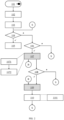
- FIG. 2 illustrates a first implementation of a method 1 in accordance with the present disclosure for group commissioning of the lighting system 2 of FIG. 1 .
- a commissioning as used herein may refer to a procedure following an installation of the luminaires 21 of the lighting system 2, and typically involving an administrative identification of the installed luminaires 21 individually, and if applicable as a group of luminaires 21, vis-à-vis a control entity.
- the method 1 may comprise, if a mains supply has become 101 available at the respective luminaire 21, a step of activating 102 the RFID reader circuit 211 of the respective luminaire 21, and a step of starting 103 a commissioning countdown timer.
- the method 1 may further comprise, if the commissioning countdown timer has expired 104, a step of deactivating 105 the RFID reader circuit 211 of the respective luminaire 21.
- the steps 101 to 105 may protect against unauthorized (re-)commissioning. Since fuse panels are typically subject to authorized access, a mains supply becoming 101 available may be taken as an authorized (re-)commissioning trigger. The (re-)commissioning may be confined to a predetermined time window of several minutes up to several days between the starting 103 and the expiry 104 of the commissioning countdown timer.
- the method 1 comprises, if an RFID tag 3 has been recognized 106 within the communications range 212 of the RFID reader circuit 211 of the respective luminaire 21, a step of reading 107 an identification number from said RFID tag 3. If no RFID tag 3 has been recognized 106 within the communications range 212, the method 1 may start over at entry point "S" (for start ") .
- the reading 107 of the identification number may comprise a step of reading 1071 a Unique Identification Number UID from a memory on the RFID tag 3 in a custom (i.e., non-standards-compliant) format, if available, and a step of reading 1072 the UID from the memory on the RFID tag 3 in a standards-compliant format otherwise.
- the reading 1072 of the UID in standards-compliant format enables using the UID of any blank RFID tag 3 for group (re-)commissioning. Note that if a blank RFID tag 3 used for commissioning of a group of luminaires 21 is lost, any group re-commissioning based on a different blank RFID tag 3 must be exercised for the whole group of luminaires 21 since the different RFID tag 3 involves a different UID.
- the reading 1071 of the UID in custom format enables to retrieve a UID of a blank RFID tag 3 saved on a spare RFID tag 3 for group re-commissioning.
- the method 1 may further comprise a step of validating 108 the identification number read from the RFID tag 3. If no identification number has been validated 108, the method 1 may start over at entry point "S".
- one or more further implementations of the method 1 may be carried out, as explained in more detail in connection with FIGs. 3 to 5 below.
- the respective implementation may be invoked via entry points "B” (for “ branch ”) and concluded via entry point "R” (for " return ").
- the method 1 further comprises a step of associating 109 the respective luminaire 21 with a group of the luminaires 21 being identified by the identification number read from the RFID tag 3.
- the method 1 may further comprise a step of confirming 110 the reading of the identification number.
- the confirming 110 of the reading of the identification number may comprise a step of flashing 1101, i.e., visibly modulating a brightness of, the respective luminaire 21.
- FIG. 3 illustrates a second implementation of the method 1 in accordance with the present disclosure for group commissioning of the lighting system of FIG. 1 .
- the method 1 may further comprise, if a different RFID tag 3 has been recognized 111 within the communications range 212 of the RFID reader circuit 211, a step of writing 112 the identification number read from the RFID tag 3 in the custom format.
- a different RFID tag as used herein may refer to an RFID tag from which an identification number is read that differs from an identification number read from a previous RFID tag.
- an identification number read 1072 from an original (previous) RFID tag 3 in a standards-compliant format may be written 112 to a spare (subsequent) RFID tag 3 in the custom format, such that the identification number may be read 1071 from the spare RFID tag 3 in said custom format.
- the method 1 may start over at entry point "R" (see FIG. 2 ).
- FIG. 4 illustrates a third implementation of the method 1 in accordance with the present disclosure for group commissioning of the lighting system of FIG. 1 .
- the method 1 may further comprise a step of reading 113 a first location of the memory of the RFID tag 3, a step of determining 114 that the first location fails to comprise a special value; and in such case a step of reading 115 further configuration parameters for the respective luminaire 21 from the RFID tag 3.
- the method 1 may start over at entry point "R" (see FIG. 2 ).
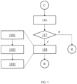
- FIG. 5 illustrates a fourth implementation of the method 1 in accordance with the present disclosure for group commissioning of the lighting system of FIG. 1 .
- the method 1 may further comprise a step of reading 116 the memory of the RFID tag 3; a step of determining 117 that the memory comprises a readout command; and a step of writing 118 the further configuration parameters of the respective luminaire 21 to the memory of the RFID tag 3.
- the further configuration parameters of the respective luminaire 21 may be retrievable via a W3C Web RFID Application Programming Interface, API.
- An NDEF message may encapsulate one or more application-defined NDEF records, and may be stored on an RFID / NFC tag or exchanged between RFID- / NFC-enabled devices.
- NDEF messages may be read by smartphone apps that are available free of charge, and included information may be recognized and processed accordingly. For example, in case of a Uniform Resource Locator (URL) a browser may open and display the corresponding web page.
- URL Uniform Resource Locator
- the reading 115 of the further configuration parameters from the RFID tag 3 is integrity protected by a message size information, an end-of-message character 0xFE, and a Cyclic Redundancy Check (CRC) checksum.
- CRC Cyclic Redundancy Check
- the writing 118 of the further configuration parameters may be incorrect if the RFID tag 3 is removed prematurely, since the message size information and the end-of-message character 0xFE do not provide any integrity protection if a message size on the RFID tag 3 is maintained.
- the writing 118 of the further configuration parameters may thus comprise a step of writing 1181 the special value (four-byte packet 0xFE 0x00 0x00 0x00), which represents an empty memory, to the first location of the memory (i.e., beginning of the User Memory Area) of the RFID tag 3; a step of writing 1182 the further configuration parameters of the respective luminaire 21 beyond their first value (four-byte payload packets no. 2 to N) to the memory of the RFID tag 3 beyond the first location; and a step of writing 1183 the first value (four-byte payload packet no. 1) of the further configuration parameters of the respective luminaire 21 to the first location of the memory of the RFID tag 3.
- the writing 1183 of the first value acknowledges an integrity of the configuration (" payload ") written 118 to the RFID tag 3.
- the method 1 may start over at entry point "R" (see FIG. 2 ).
Landscapes
- Engineering & Computer Science (AREA)
- Computer Networks & Wireless Communication (AREA)
- Circuit Arrangement For Electric Light Sources In General (AREA)
Abstract
Description
- The present disclosure relates to lighting technology, and in particular to a method for group commissioning of a lighting system and to a corresponding lighting system.
- Luminaires may be commissioned in various ways.
- Commissioning through network access (e.g., wire-less or wire-bound) via a central control device is expensive as it requires further hardware and software.
- Commissioning through physical access (e.g., buttons, panel, DIP switches) is more economical, but may be more dangerous and more difficult to achieve when luminaires are arranged on a high ceiling, since a ladder or the like may be required to access the luminaires.
- Commissioning through a radio-frequency identification (RFID) based technology, wherein a luminaire's driver includes an RFID tag which can be written to by means of an RFID reader in proximity, requires a commissioning device including said RFID reader as well as further software, and typically depends on adequate battery power.
- In view of the above-mentioned drawbacks and limitations, the present disclosure aims to improve a commissioning of the luminaires, particularly with regard to a grouping of the luminaires (group commissioning), of a lighting system.
- The objective is achieved by the embodiments as defined by the appended independent claims. Preferred embodiments are set forth in the dependent claims and in the following description and drawings.
- A first aspect of the present disclosure relates to a method for group commissioning of a lighting system. The lighting system comprises a plurality of luminaires, respectively comprising a technology based on Radio-Frequency Identification, RFID, reader circuit for passive RFID tags. The method comprises: reading an identification number from an RFID tag recognized within a communications range of the RFID reader circuit of the respective luminaire; and associating the respective luminaire with a group of the luminaires being identified by the identification number read from the RFID tag.
- The reading of the identification number may comprise: reading a Unique Identification Number, UID, from a memory on the RFID tag in a custom format, if available, and reading the UID from the memory on the RFID tag in a standards-compliant format otherwise.
- In case NFC is used it is warranted by the standard ISO/IEC 14443-3 that the 7 byte UID is unique. Therefore the resulting group number is also unique.
- The method may further comprise: validating the identification number read from the RFID tag.
- The method may further comprise: confirming the reading of the identification number.
- The confirming of the reading of the identification number may comprise: flashing the respective luminaire.
- The method may further comprise: writing the identification number read from the RFID tag to a different RFID tag recognized within the communications range of the RFID reader circuit in the custom format.
- The method may further comprise: reading a first location of the memory of the RFID tag; determining that the first location fails to comprise a special value; and reading further configuration parameters for the respective luminaire from the RFID tag.
- The method may further comprise: reading the memory of the RFID tag; determining that the memory comprises a readout command; and writing the further configuration parameters of the respective luminaire to the memory of the RFID tag.
- The writing of the further configuration parameters may comprise: writing the special value to the first location of the memory of the RFID tag; writing the further configuration parameters of the respective luminaire beyond their first value to the memory of the RFID tag beyond the first location; and writing the first value of the further configuration parameters of the respective luminaire to the first location of the memory of the RFID tag.
- The further configuration parameters of the respective luminaire may be retrievable via a W3C Web RFID Application Programming Interface, API.
- The method may further comprise: if a mains supply has become available at the respective luminaire, activating the RFID reader circuit of the respective luminaire; and starting a commissioning countdown timer; and if the commissioning countdown timer has expired, deactivating the RFID reader circuit of the respective luminaire.
- The respective luminaire may comprise magnetic alignment means corresponding to magnetic alignment means of the RFID tag.
- The RFID reader circuit of the respective luminaire may comprise one of: an RFID reader, and an RFID reader-writer.
- A second aspect of the present disclosure relates to a lighting system, comprising a plurality of luminaires, respectively comprising a Radio-Frequency Identification, RFID, reader circuit for passive RFID tags. The RFID reader circuit may be configured to read an identification number from an RFID tag recognized within a communications range of the RFID reader circuit of the respective luminaire. The respective luminaire may be configured to associate with a group of the luminaires being identified by the identification number read from the RFID tag.
- One of the plurality of luminaires may comprise a sensor, being configured to participate in controlling an operation of the group of the luminaires.
- The present disclosure enables a commissioning of luminaires arranged on a high ceiling in a straightforward manner, without the risk of work-related injuries and the deficiencies of a commissioning device, such as cost, haptics and powering.
- The technical effects and advantages described in relation with the method according to the first aspect equally apply to the lighting system according to the second aspect having corresponding features, and vice versa.
- The above-described aspects and implementations will now be explained with reference to the accompanying drawings, in which the same or similar reference numerals designate the same or similar elements.
- The features of these aspects and implementations may be combined with each other unless specifically stated otherwise.
- The drawings are to be regarded as being schematic representations, and elements illustrated in the drawings are not necessarily shown to scale. Rather, the various elements are represented such that their function and general purpose become apparent to those skilled in the art.
- FIG. 1
- illustrates a lighting system 2 in accordance with the present disclosure; and
- FIGs. 2 to 5
- illustrate various implementations of a method 1 in accordance with the present disclosure for group commissioning of the lighting system 2 of
FIG. 1 . -
FIG. 1 illustrates a lighting system 2 in accordance with the present disclosure. - The lighting system 2 comprises a plurality of
luminaires 21. Without loss of generality, the example ofFIG. 1 includes a plurality of fourluminaires 21. - The
respective luminaire 21 comprises an Radio-Frequency IdentificationRFID reader circuit 211 forpassive RFID tags 3. RFID as used herein may refer to a set of radio-frequency identification technologies, including Near-Field Communication NFC technology. A passive RFID tag as used herein may refer to an RF transponder i.e., receiver and transmitter, which is configured to transmit digital data, typically including an identification number, in response to an RF interrogation pulse issued by a nearby RFID reader circuit. - The
RFID reader circuit 211 of therespective luminaire 21 may comprise one of: an RFID reader, and an RFID reader-writer. An RFID reader as used herein may refer to an RFID device having read-only access toRFID tags 3. An RFID reader-writer as used herein may refer to an RFID device having read and write access toRFID tags 3. - The
RFID reader circuit 211 of therespective luminaire 21 may be associated with acommunications range 212. - The
RFID reader circuit 211 of therespective luminaire 21 may be configured to read 107 an identification number from anRFID tag 3 recognized 106 within saidcommunications range 212 of theRFID reader circuit 211 of therespective luminaire 21. - The
RFID tag 3 may preferably be designed as a business card and imprinted with one or more of: support contact information, a quick reference guide in the form of text and/or a QR code, and blank fields/boxes for further configuration parameters, if any. - Especially when the
respective luminaire 21 is arranged on a high ceiling, theRFID tag 3 may be brought into, and thus recognized within, thecommunications range 212 of itsRFID reader circuit 211 by means of a long stick or the like, as indicated inFIG. 1 . - The
respective luminaire 21 may be configured to associate 109 with a group of theluminaires 21 being identified by the identification number read from theRFID tag 3. - The
respective luminaire 21 may further comprise magnetic alignment means 214 corresponding to magnetic alignment means of theRFID tag 3. - One of the plurality of
luminaires 21, such as the leftmost one inFIG. 1 , may comprise asensor 213, being configured to participate in controlling an operation of the group of theluminaires 21. For example, a dimming or (de)activation of the plurality ofluminaires 21 of the lighting system 2 may depend on a sensing signal of an ambient light ormotion sensor 213. The controlling may be exercised via any kind of wire-less or wire-bound network connectivity among the plurality ofluminaires 21, as suggested inFIG. 1 . -
FIG. 2 illustrates a first implementation of a method 1 in accordance with the present disclosure for group commissioning of the lighting system 2 ofFIG. 1 . - A commissioning as used herein may refer to a procedure following an installation of the
luminaires 21 of the lighting system 2, and typically involving an administrative identification of the installedluminaires 21 individually, and if applicable as a group ofluminaires 21, vis-à-vis a control entity. - The method 1 may comprise, if a mains supply has become 101 available at the
respective luminaire 21, a step of activating 102 theRFID reader circuit 211 of therespective luminaire 21, and a step of starting 103 a commissioning countdown timer. - The method 1 may further comprise, if the commissioning countdown timer has expired 104, a step of deactivating 105 the
RFID reader circuit 211 of therespective luminaire 21. - The
steps 101 to 105 may protect against unauthorized (re-)commissioning. Since fuse panels are typically subject to authorized access, a mains supply becoming 101 available may be taken as an authorized (re-)commissioning trigger. The (re-)commissioning may be confined to a predetermined time window of several minutes up to several days between the starting 103 and theexpiry 104 of the commissioning countdown timer. - The method 1 comprises, if an
RFID tag 3 has been recognized 106 within the communications range 212 of theRFID reader circuit 211 of therespective luminaire 21, a step of reading 107 an identification number from saidRFID tag 3. If noRFID tag 3 has been recognized 106 within thecommunications range 212, the method 1 may start over at entry point "S" (for start"). - The reading 107 of the identification number may comprise a step of reading 1071 a Unique Identification Number UID from a memory on the
RFID tag 3 in a custom (i.e., non-standards-compliant) format, if available, and a step of reading 1072 the UID from the memory on theRFID tag 3 in a standards-compliant format otherwise. The reading 1072 of the UID in standards-compliant format enables using the UID of anyblank RFID tag 3 for group (re-)commissioning. Note that if ablank RFID tag 3 used for commissioning of a group ofluminaires 21 is lost, any group re-commissioning based on a differentblank RFID tag 3 must be exercised for the whole group ofluminaires 21 since thedifferent RFID tag 3 involves a different UID. As such, the reading 1071 of the UID in custom format enables to retrieve a UID of ablank RFID tag 3 saved on aspare RFID tag 3 for group re-commissioning. - The method 1 may further comprise a step of validating 108 the identification number read from the
RFID tag 3. If no identification number has been validated 108, the method 1 may start over at entry point "S". - In parallel, one or more further implementations of the method 1 may be carried out, as explained in more detail in connection with
FIGs. 3 to 5 below. The respective implementation may be invoked via entry points "B" (for "branch ") and concluded via entry point "R" (for "return "). - The method 1 further comprises a step of associating 109 the
respective luminaire 21 with a group of theluminaires 21 being identified by the identification number read from theRFID tag 3. - The method 1 may further comprise a step of confirming 110 the reading of the identification number. For example, the confirming 110 of the reading of the identification number may comprise a step of flashing 1101, i.e., visibly modulating a brightness of, the
respective luminaire 21. -
FIG. 3 illustrates a second implementation of the method 1 in accordance with the present disclosure for group commissioning of the lighting system ofFIG. 1 . - Starting from entry point "B", the method 1 may further comprise, if a
different RFID tag 3 has been recognized 111 within the communications range 212 of theRFID reader circuit 211, a step of writing 112 the identification number read from theRFID tag 3 in the custom format. A different RFID tag as used herein may refer to an RFID tag from which an identification number is read that differs from an identification number read from a previous RFID tag. In other words, an identification number read 1072 from an original (previous)RFID tag 3 in a standards-compliant format may be written 112 to a spare (subsequent)RFID tag 3 in the custom format, such that the identification number may be read 1071 from thespare RFID tag 3 in said custom format. - Subsequently to the writing 112, or if no
different RFID tag 3 has been recognized 106 within thecommunications range 212, the method 1 may start over at entry point "R" (seeFIG. 2 ). -
FIG. 4 illustrates a third implementation of the method 1 in accordance with the present disclosure for group commissioning of the lighting system ofFIG. 1 . - Starting from entry point "B", the method 1 may further comprise a step of reading 113 a first location of the memory of the
RFID tag 3, a step of determining 114 that the first location fails to comprise a special value; and in such case a step of reading 115 further configuration parameters for therespective luminaire 21 from theRFID tag 3. - This enables a "download" of a previously "uploaded" configuration of a luminaire 21 (or of configuration values previously written by an App or Web API) from the recognized 106
RFID tag 3, and thus a transfer of a configuration betweenluminaires 21 of a same group. - Subsequently to the reading 115, or if the first location comprises the special value, which represents an empty memory, the method 1 may start over at entry point "R" (see
FIG. 2 ). -
FIG. 5 illustrates a fourth implementation of the method 1 in accordance with the present disclosure for group commissioning of the lighting system ofFIG. 1 . - Starting from entry point "B", the method 1 may further comprise a step of reading 116 the memory of the
RFID tag 3; a step of determining 117 that the memory comprises a readout command; and a step of writing 118 the further configuration parameters of therespective luminaire 21 to the memory of theRFID tag 3. - This enables an "upload" of a configuration of a
luminaire 21 to the recognized 106RFID tag 3, by rewriting a recognized readout command by the configuration of theluminaire 21. - The further configuration parameters of the
respective luminaire 21 may be retrievable via a W3C Web RFID Application Programming Interface, API. - This enables a generation of a configuration for
luminaires 21 of a same group, in accordance with the standardized NFC Forum Data Exchange Format (NDEF). An NDEF message may encapsulate one or more application-defined NDEF records, and may be stored on an RFID / NFC tag or exchanged between RFID- / NFC-enabled devices. NDEF messages may be read by smartphone apps that are available free of charge, and included information may be recognized and processed accordingly. For example, in case of a Uniform Resource Locator (URL) a browser may open and display the corresponding web page. - The reading 115 of the further configuration parameters from the
RFID tag 3 is integrity protected by a message size information, an end-of-message character 0xFE, and a Cyclic Redundancy Check (CRC) checksum. However, the writing 118 of the further configuration parameters may be incorrect if theRFID tag 3 is removed prematurely, since the message size information and the end-of-message character 0xFE do not provide any integrity protection if a message size on theRFID tag 3 is maintained. - The writing 118 of the further configuration parameters may thus comprise a step of writing 1181 the special value (four-byte packet 0xFE 0x00 0x00 0x00), which represents an empty memory, to the first location of the memory (i.e., beginning of the User Memory Area) of the
RFID tag 3; a step of writing 1182 the further configuration parameters of therespective luminaire 21 beyond their first value (four-byte payload packets no. 2 to N) to the memory of theRFID tag 3 beyond the first location; and a step of writing 1183 the first value (four-byte payload packet no. 1) of the further configuration parameters of therespective luminaire 21 to the first location of the memory of theRFID tag 3. The writing 1183 of the first value acknowledges an integrity of the configuration ("payload") written 118 to theRFID tag 3. - Subsequently to the writing 118, or if the memory fails to comprise the readout command, the method 1 may start over at entry point "R" (see
FIG. 2 ).
Claims (15)
- A method (1) for group commissioning of a lighting system (2),the lighting system (2) comprising
a plurality of luminaires (21), respectively comprising
a Radio-Frequency Identification, RFID, reader circuit (211) for passive RFID tags (3);the method (1) comprising:- reading (107) an identification number from an RFID tag (3) recognized (106) within a communications range (212) of the RFID reader circuit (211) of the respective luminaire (21); and- associating (109) the respective luminaire (21) with a group of the luminaires (21) being identified by the identification number read from the RFID tag (3). - The method (1) of claim 1, the reading (107) of the identification number comprising:- reading (1071) a Unique Identification Number, UID, from a memory on the RFID tag (3) in a custom format, if available, and- reading (1072) the UID from the memory on the RFID tag (3) in a standards-compliant format otherwise.
- The method (1) of claim 1 or claim 2, further comprising:- validating (108) the identification number read from the RFID tag (3).
- The method (1) of any one of the preceding claims, further comprising:- confirming (110) the reading of the identification number.
- The method (1) of claim 4, the confirming (110) of the reading of the identification number comprising:- flashing (1101) the respective luminaire (21).
- The method (1) of any one of the claims 2 to 5, further comprising- writing (112) the identification number read from the RFID tag (3) to a different RFID tag (3) recognized (111) within the communications range (212) of the RFID reader circuit (211) in the custom format.
- The method (1) of any one of the claims 2 to 6, further comprising:- reading (113) a first location of the memory of the RFID tag (3);- determining (114) that the first location fails to comprise a special value; and- reading (115) further configuration parameters for the respective luminaire (21) from the RFID tag (3).
- The method (1) of any one of the claims 2 to 7, further comprising- reading (116) the memory of the RFID tag (3);- determining (117) that the memory comprises a readout command; and- writing (118) the further configuration parameters of the respective luminaire (21) to the memory of the RFID tag (3).
- The method (1) of claim 7,
the writing (118) of the further configuration parameters comprising- writing (1181) the special value to the first location of the memory of the RFID tag (3);- writing (1182) the further configuration parameters of the respective luminaire (21) beyond their first value to the memory of the RFID tag (3) beyond the first location; and- writing (1183) the first value of the further configuration parameters of the respective luminaire (21) to the first location of the memory of the RFID tag (3). - The method (1) of any one of the claims 7 to 9,- the further configuration parameters of the respective luminaire (21) being retrievable via a W3C Web RFID Application Programming Interface, API.
- The method (1) of any one of the preceding claims, further comprising- if a mains supply has become (101) available at the respective luminaire (21),- activating (102) the RFID reader circuit (211) of the respective luminaire (21); and- starting (103) a commissioning countdown timer; and- if the commissioning countdown timer has expired (104),- deactivating (105) the RFID reader circuit (211) of the respective luminaire (21).
- The method (1) of any one of the preceding claims,
the respective luminaire (21) comprising magnetic alignment means corresponding to magnetic alignment means of the RFID tag (3). - The method (1) of any one of the preceding claims,
the RFID reader circuit (211) of the respective luminaire (21) comprising one of:an RFID reader, andan RFID reader-writer. - A lighting system (2), comprisinga plurality of luminaires (21), respectively comprising
a Radio-Frequency Identification, RFID, reader circuit (211) for passive RFID tags (3), the RFID reader circuit (211) being configured to- read (107) an identification number from an RFID tag (3) recognized (106) within a communications range (212) of the RFID reader circuit (211) of the respective luminaire (21);the respective luminaire (21) being configured to- associate (109) with a group of the luminaires (21) being identified by the identification number read from the RFID tag (3). - The lighting system (2) of claim 13,
one of the plurality of luminaires (21) comprising
a sensor (213), being configured to- participate in controlling an operation of the group of the luminaires (21).
Priority Applications (2)
| Application Number | Priority Date | Filing Date | Title |
|---|---|---|---|
| EP22212210.3A EP4383950A1 (en) | 2022-12-08 | 2022-12-08 | Rfid-based group commissioning of a lighting system |
| PCT/EP2023/082115 WO2024120789A1 (en) | 2022-12-08 | 2023-11-16 | Rfid-based group commissioning of a lighting system |
Applications Claiming Priority (1)
| Application Number | Priority Date | Filing Date | Title |
|---|---|---|---|
| EP22212210.3A EP4383950A1 (en) | 2022-12-08 | 2022-12-08 | Rfid-based group commissioning of a lighting system |
Publications (1)
| Publication Number | Publication Date |
|---|---|
| EP4383950A1 true EP4383950A1 (en) | 2024-06-12 |
Family
ID=84462882
Family Applications (1)
| Application Number | Title | Priority Date | Filing Date |
|---|---|---|---|
| EP22212210.3A Pending EP4383950A1 (en) | 2022-12-08 | 2022-12-08 | Rfid-based group commissioning of a lighting system |
Country Status (2)
| Country | Link |
|---|---|
| EP (1) | EP4383950A1 (en) |
| WO (1) | WO2024120789A1 (en) |
Citations (3)
| Publication number | Priority date | Publication date | Assignee | Title |
|---|---|---|---|---|
| WO2008029323A1 (en) * | 2006-09-06 | 2008-03-13 | Philips Intellectual Property & Standards Gmbh | Lighting control |
| US20110266345A1 (en) * | 2010-05-03 | 2011-11-03 | Redwood Systems, Inc. | Radio frequency identification of lighting fixtures |
| WO2015140654A1 (en) * | 2014-03-17 | 2015-09-24 | Koninklijke Philips N.V. | Wirelessly-controllable portable luminaire |
-
2022
- 2022-12-08 EP EP22212210.3A patent/EP4383950A1/en active Pending
-
2023
- 2023-11-16 WO PCT/EP2023/082115 patent/WO2024120789A1/en not_active Ceased
Patent Citations (3)
| Publication number | Priority date | Publication date | Assignee | Title |
|---|---|---|---|---|
| WO2008029323A1 (en) * | 2006-09-06 | 2008-03-13 | Philips Intellectual Property & Standards Gmbh | Lighting control |
| US20110266345A1 (en) * | 2010-05-03 | 2011-11-03 | Redwood Systems, Inc. | Radio frequency identification of lighting fixtures |
| WO2015140654A1 (en) * | 2014-03-17 | 2015-09-24 | Koninklijke Philips N.V. | Wirelessly-controllable portable luminaire |
Also Published As
| Publication number | Publication date |
|---|---|
| WO2024120789A1 (en) | 2024-06-13 |
Similar Documents
| Publication | Publication Date | Title |
|---|---|---|
| AU665797B2 (en) | Multi-memory electronic identification tag | |
| US5257011A (en) | Data altering means for multi-memory electronic identification tag | |
| US5499017A (en) | Multi-memory electronic identification tag | |
| EP2800403A1 (en) | Communication tag, system and method | |
| EP2336946B1 (en) | Configuration RFID circuit | |
| US8633796B2 (en) | Information processing system, control information processing device, and program | |
| FI3362961T3 (en) | Electronic price, inventory management and label system | |
| CN205068417U (en) | NFC label anti -counterfeit device and NFC label system that guards against falsification | |
| US20060142876A1 (en) | Location-specific adaptation of an intelligent unit | |
| CN113392940B (en) | Computer device in an aircraft galley insert and system for setting up an aircraft galley insert | |
| US10931331B2 (en) | Communication device and method | |
| WO2024120789A1 (en) | Rfid-based group commissioning of a lighting system | |
| CN106897750A (en) | Improved physical access control system | |
| ES2243096T3 (en) | PROCEDURE, CHIP CARD AND APPLIANCE FOR A LOGICAL INTERFACE BETWEEN TWO APPLICATIONS. | |
| EP2306415A1 (en) | Communication device, communication method, information processing device, information processing method, program, and communication system | |
| US8220718B2 (en) | Method for post-manufacturing data transfer to and from a sealed device | |
| Kumar et al. | Zigbee based indoor campus inventory tracking using RFID module | |
| US20170053292A1 (en) | Method of checking the authenticity of an object | |
| KR100847787B1 (en) | Secure RFID tag and RFID reader (or terminal) authentication method and system for authenticating RFID reader (or terminal) and recording medium therefor | |
| KR100726086B1 (en) | RFID communication terminal, RFID-based wireless service system and method using same | |
| KR101236854B1 (en) | Method for Managing Production of Manufactures | |
| JP6506158B2 (en) | Parts management system | |
| US20060273906A1 (en) | Method and system for setting parameters of a field station in a communications network | |
| KR101263465B1 (en) | Method for Managing Production Record | |
| CN103632173A (en) | Tag access and access processing method and device |
Legal Events
| Date | Code | Title | Description |
|---|---|---|---|
| PUAI | Public reference made under article 153(3) epc to a published international application that has entered the european phase |
Free format text: ORIGINAL CODE: 0009012 |
|
| STAA | Information on the status of an ep patent application or granted ep patent |
Free format text: STATUS: THE APPLICATION HAS BEEN PUBLISHED |
|
| AK | Designated contracting states |
Kind code of ref document: A1 Designated state(s): AL AT BE BG CH CY CZ DE DK EE ES FI FR GB GR HR HU IE IS IT LI LT LU LV MC ME MK MT NL NO PL PT RO RS SE SI SK SM TR |
|
| STAA | Information on the status of an ep patent application or granted ep patent |
Free format text: STATUS: REQUEST FOR EXAMINATION WAS MADE |
|
| 17P | Request for examination filed |
Effective date: 20240724 |
|
| RBV | Designated contracting states (corrected) |
Designated state(s): AL AT BE BG CH CY CZ DE DK EE ES FI FR GB GR HR HU IE IS IT LI LT LU LV MC ME MK MT NL NO PL PT RO RS SE SI SK SM TR |
|
| STAA | Information on the status of an ep patent application or granted ep patent |
Free format text: STATUS: EXAMINATION IS IN PROGRESS |
|
| 17Q | First examination report despatched |
Effective date: 20260402 |