EP4383806A1 - Communication system and communication control method - Google Patents
Communication system and communication control method Download PDFInfo
- Publication number
- EP4383806A1 EP4383806A1 EP21952911.2A EP21952911A EP4383806A1 EP 4383806 A1 EP4383806 A1 EP 4383806A1 EP 21952911 A EP21952911 A EP 21952911A EP 4383806 A1 EP4383806 A1 EP 4383806A1
- Authority
- EP
- European Patent Office
- Prior art keywords
- base station
- shaping
- rate
- traffic flow
- radio quality
- Prior art date
- Legal status (The legal status is an assumption and is not a legal conclusion. Google has not performed a legal analysis and makes no representation as to the accuracy of the status listed.)
- Pending
Links
Images





Classifications
-
- H—ELECTRICITY
- H04—ELECTRIC COMMUNICATION TECHNIQUE
- H04W—WIRELESS COMMUNICATION NETWORKS
- H04W28/00—Network traffic management; Network resource management
- H04W28/02—Traffic management, e.g. flow control or congestion control
- H04W28/10—Flow control between communication endpoints
-
- H—ELECTRICITY
- H04—ELECTRIC COMMUNICATION TECHNIQUE
- H04W—WIRELESS COMMUNICATION NETWORKS
- H04W28/00—Network traffic management; Network resource management
- H04W28/02—Traffic management, e.g. flow control or congestion control
- H04W28/0231—Traffic management, e.g. flow control or congestion control based on communication conditions
- H04W28/0236—Traffic management, e.g. flow control or congestion control based on communication conditions radio quality, e.g. interference, losses or delay
-
- H—ELECTRICITY
- H04—ELECTRIC COMMUNICATION TECHNIQUE
- H04L—TRANSMISSION OF DIGITAL INFORMATION, e.g. TELEGRAPHIC COMMUNICATION
- H04L47/00—Traffic control in data switching networks
- H04L47/10—Flow control; Congestion control
- H04L47/22—Traffic shaping
-
- H—ELECTRICITY
- H04—ELECTRIC COMMUNICATION TECHNIQUE
- H04L—TRANSMISSION OF DIGITAL INFORMATION, e.g. TELEGRAPHIC COMMUNICATION
- H04L47/00—Traffic control in data switching networks
- H04L47/10—Flow control; Congestion control
- H04L47/22—Traffic shaping
- H04L47/225—Determination of shaping rate, e.g. using a moving window
-
- H—ELECTRICITY
- H04—ELECTRIC COMMUNICATION TECHNIQUE
- H04L—TRANSMISSION OF DIGITAL INFORMATION, e.g. TELEGRAPHIC COMMUNICATION
- H04L47/00—Traffic control in data switching networks
- H04L47/10—Flow control; Congestion control
- H04L47/24—Traffic characterised by specific attributes, e.g. priority or QoS
- H04L47/2483—Traffic characterised by specific attributes, e.g. priority or QoS involving identification of individual flows
-
- H—ELECTRICITY
- H04—ELECTRIC COMMUNICATION TECHNIQUE
- H04L—TRANSMISSION OF DIGITAL INFORMATION, e.g. TELEGRAPHIC COMMUNICATION
- H04L47/00—Traffic control in data switching networks
- H04L47/10—Flow control; Congestion control
- H04L47/28—Flow control; Congestion control in relation to timing considerations
- H04L47/283—Flow control; Congestion control in relation to timing considerations in response to processing delays, e.g. caused by jitter or round trip time [RTT]
-
- H—ELECTRICITY
- H04—ELECTRIC COMMUNICATION TECHNIQUE
- H04W—WIRELESS COMMUNICATION NETWORKS
- H04W88/00—Devices specially adapted for wireless communication networks, e.g. terminals, base stations or access point devices
- H04W88/12—Access point controller devices
Definitions
- the present invention relates to technology of a communication system that accommodates wireless terminals, and a communication control apparatus.
- This application claims priority on the basis of PCT/JP2021/29119 filed on August 5, 2021 , the content of which is hereby incorporated by reference.
- hybrid automatic repeat request hybrid ARQ
- hybrid ARQ hybrid automatic repeat request
- Fig. 8 is a diagram illustrating a configuration example of a mobile communication system 90 according to the related art.
- the mobile communication system 90 includes, for example, a server 91, one or more transfer apparatuses 92, a transfer apparatus controller 93, and a base station 94.
- the server 91 is an apparatus that communicates with the wireless terminal 95.
- the one or more transfer apparatuses 92 are apparatuses that constitute a transfer apparatus network 96 and transfer signals exchanged between the server 91 and the wireless terminal 95.
- the transfer apparatus controller 93 is an apparatus that controls the one or more transfer apparatuses 92 by transmitting a control signal.
- the base station 94 is an apparatus that communicates with the wireless terminal 95, transmits a signal transferred from the transfer apparatus 92 to the wireless terminal 95, and transfers a signal received from the wireless terminal 95 to the transfer apparatus 92.
- Fig. 9 is a diagram illustrating a configuration example of a mobile communication system 90a according to the related art.
- the mobile communication system 90a includes, for example, a server 91a, one or more transfer apparatuses 92a, a transfer apparatus controller 93a, and a base station 94a.
- the server 91a is an apparatus that communicates with each of one or more wireless terminals 95a.
- the one or more transfer apparatuses 92a constitute a transfer apparatus network 96a and are apparatuses that transfer a signal exchanged between the server 91a and each wireless terminal 95a.
- the transfer apparatus controller 93a is an apparatus that controls the one or more transfer apparatuses 92a by transmitting a control signal.
- the base station 94a is an apparatus that communicates with each of the one or more wireless terminals 95a, transmits a signal transferred from the transfer apparatus 92a to each of the one or more wireless terminals 95a, and transfers a signal received from each of the one or more wireless terminals 95a to the transfer apparatus 92a.
- the wireless terminal 95a has one or more traffic flows.
- an object of the present invention is to provide a technology capable of suppressing delay jitter.
- An aspect of the present invention is a communication system including one or more base stations configured to accommodate wireless terminals, one or more transfer apparatuses configured to transfer uplink communication of the wireless terminal received via the base station to an upper side, and a transfer apparatus controller configured to control the one or more transfer apparatuses, the communication system including: an information acquisition unit configured to acquire information on wireless communication between the base station and the wireless terminal for each traffic flow; a rate determination unit configured to determine a shaping rate of traffic shaping for each traffic flow, so that delay jitter in the base station is mitigated on an upper side with respect to the base station, on the basis of the information on the wireless communication for each traffic flow; and a communication control unit configured to execute the traffic shaping on the upper side with respect to the base station on the basis of the shaping rate determined by the rate determination unit.
- An aspect of the present invention is, in a communication system including one or more base stations configured to accommodate wireless terminals, one or more transfer apparatuses configured to transfer uplink communication of the wireless terminal received via the base station to an upper side, and a transfer apparatus controller configured to control the one or more transfer apparatuses, a communication control method including: an information acquisition step of acquiring information on wireless communication between the base station and the wireless terminal for each traffic flow; a rate determination unit of determining a shaping rate of traffic shaping for each traffic flow, so that delay jitter in the base station is mitigated on an upper side with respect to the base station, on the basis of the information on the wireless communication for each traffic flow; and a communication control step of executing the traffic shaping on the upper side with respect to the base station on the basis of the shaping rate determined in the rate determination step.
- Fig. 1 is a diagram illustrating a system configuration example of a mobile communication system 1A of the first embodiment.
- the mobile communication system 1A includes, for example, one or more transfer apparatuses 10, a transfer apparatus controller 20, and one or more base stations 30.
- a server SV is an apparatus that communicates with each of one or more wireless terminals CL.
- the one or more transfer apparatuses 10 constitute a transfer apparatus network TN, and transfer a signal exchanged between the server SV and the one or more wireless terminals CL.
- the transfer apparatus controller 20 is an apparatus that controls the one or more transfer apparatuses 10 by transmitting a control signal.
- the base station 30 is an apparatus that communicates with each of the one or more wireless terminals CL, transmits a signal transferred from the transfer apparatus 10 to the wireless terminal CL, and transfers a signal received from the wireless terminals CL to the transfer apparatus 10.
- Each of the one or more wireless terminals CL has one or more traffic flows.
- the transfer apparatus controller 20 is communicatively connected to each of the one or more transfer apparatuses 10 and the base station 30.
- the one or more transfer apparatuses 10, the transfer apparatus controller 20, and the base station 30 included in the mobile communication system 1A are configured using, for example, a processor such as a central processing unit (CPU), a memory, and a communication interface.
- a processor such as a central processing unit (CPU), a memory, and a communication interface.
- Each of the one or more transfer apparatuses 10, the transfer apparatus controller 20, and the base station 30 functions as a communication apparatus including a control unit by the processor executing a program.
- the control unit provides each function for causing the communication apparatus to function as the transfer apparatus 10, the transfer apparatus controller 20, or the base station 30. All or some of respective functions of the control unit may be realized using hardware such as an application specific integrated circuit (ASIC), a programmable logic device (PLD), or a field programmable gate array (FPGA).
- ASIC application specific integrated circuit
- PLD programmable logic device
- FPGA field programmable gate array
- the program may be recorded on a computer-readable recording medium.
- the computer-readable recording medium is a storage apparatus such as a portable medium such as a flexible disk, a magneto-optical disc, a ROM, a CD-ROM, a semiconductor storage apparatus (such as SSD: Solid State Drives), or a hard disk or a semiconductor storage apparatus built into a computer system.
- the above program may be transmitted via a telecommunication line.
- Fig. 2 is a diagram illustrating a specific example of a functional configuration of the mobile communication system 1A of the first embodiment.
- the mobile communication system 1A includes, for example, one or more information acquisition units 101A, a rate determination units 102A, and one or more communication control units 103.
- the information acquisition unit 101A acquires information on wireless communication between the base station 30 and the wireless terminal CL (hereinafter referred to as "wireless communication information").
- the rate determination unit 102A collects the wireless communication information acquired by each of one or more information acquisition units 101A, and determines, for each traffic flow, a shaping rate of traffic shaping so that delay jitter in the base station 30 is mitigated in the upper side with respect to the base station 30, on the basis of the collected wireless communication information.
- the communication control unit 103 (communication controller) executes the traffic shaping on the upper side with respect to the base station 30 on the basis of the shaping rate determined by the rate determination unit 102A.
- the information acquisition unit 101A is included in a control unit of the base station 30, the rate determination unit 102A is included in a control unit of the transfer apparatus controller 20, and the communication control unit 103 is included in a control unit of the transfer apparatus 10.
- one or more information acquisition units 101A acquire information including control information on the quality of wireless communication between the base station 30 and the wireless terminal CL (hereinafter referred to as "the radio quality information"), as the wireless communication information, and transmit the acquired radio quality information to the transfer apparatus controller 20.
- the radio quality information includes information on communication quality for each traffic flow in wireless communication between the base station 30 and the wireless terminal CL, and information indicating a priority of each traffic flow.
- the rate determination unit 102A (rate determiner) collects the radio quality information acquired by each of the one or more information acquisition units 101A, and determines the shaping rate for each traffic flow on the basis of the collected radio quality information.
- the rate determination unit 102A considers the priority of each traffic flow in a range in which a predetermined delay requirement is satisfied, and then, determines the shaping rate of the traffic shaping for each traffic flow so that the delay jitter in the base station 30 is mitigated on the upper side with respect to the base station 30.
- the rate determination unit 102A notifies the communication control unit 103 of the transfer apparatus 10 of the determined shaping rate.
- the communication control unit 103 executes the traffic shaping of its own apparatus on the basis of the shaping rate notified from the rate determination unit 102A of the transfer apparatus controller 20.
- the radio quality information acquired as the wireless communication information is, for example, 5G QoS indicator (5QI) assigned to a header of an N3 interface signal in fifth generation (5G) mobile communication, or a PDCP SDU data volume for each 5QI.
- 5QI 5G QoS indicator assigned to a header of an N3 interface signal in fifth generation (5G) mobile communication
- PDCP SDU data volume for each 5QI.
- the rate determination unit 102A of the transfer apparatus controller 20 stores in advance an association table (association information) in which appropriate shaping rate candidates determined according to a value of the 5QI in advance are associated with the value of the 5QI, and the shaping rate associated with the 5QI value (the radio quality information) acquired from the base station 30 is determined as the shaping rate to be applied to the transfer apparatus 10 in this association table.
- the appropriate shaping rate is a communication rate that is low enough to narrow the communication band so that the delay jitter in the base station 30 is mitigated on the upper side with respect to the base station 30 while maintaining at least a minimum required communication rate.
- examples of the radio quality information acquired as the wireless communication information may include a scheduling request, an uplink grant, and a buffer status report, which the base station 30 receives from the wireless terminal CL, and a radio frame number, subframe number, and slot number at which the base station has received the scheduling request, uplink grant, and buffer status report.
- the scheduling request is information that a wireless terminal transmits to a base station to notify of the start of the uplink communication.
- the uplink grant is information transmitted by a base station in downlink communication in order to notify a wireless terminal of a wireless communication scheme in which uplink communication is permitted or frequency resource allocation, and indirectly shows an amount of data of the uplink communication.
- the buffer status report is information transmitted by a wireless terminal to notify the base station of how much data is held in the buffer.
- the radio frame number, subframe number, and slot number are numbers on the three-stage data basis transmitted by wireless communication, a radio frame is defined as 10 [ms], a subframe is defined as 1 [ms], and a slot is defined as, for example, a length selected from among a plurality of values such as 1 [ms] and 0.5 [ms], and it is possible to obtain a transmission/reception timing of the wireless communication from these numbers.
- the scheduling request, the uplink grant, and the buffer status report are transmitted in association with a radio frame number, subframe number, and slot number indicating a transmission timing for uplink communication.
- the rate determination unit 102A collects the radio quality information acquired by each of the one or more information acquisition units 101A, and determines an appropriate shaping rate for each traffic flow through calculation on the basis of the collected radio quality information.
- the rate determination unit 102A recognizes an amount of data buffered in the wireless terminal CL by the buffer status report received from the wireless terminal CL (hereinafter referred to as "buffer data"), and calculates, as an appropriate shaping rate, a communication rate low enough to narrow a communication band so that the delay jitter in the base station 30 is mitigated on the upper side with respect to the base station 30 while maintaining at least a minimum required communication rate for transmission of the buffer data having the amount of data.
- the shaping rate is initialized, and the radio frame number, subframe number, and slot number associated with the acquired the scheduling request are held. Thereafter, the shaping rate is updated each time the rate determination unit 102A acquires the buffer status report from the information acquisition unit 101A.
- the shaping rate is determined by adding a cumulative value of an amount of data in uplink communication calculated from one or more uplink grants acquired from the information acquisition unit 101A by the rate determination unit 102A between a radio frame number, subframe number, and slot number associated with the scheduling request and a radio frame number, subframe number, and slot number associated with the buffer status report, to an amount of data held by the wireless terminal notified by the buffer status report, and performing division at time intervals calculated from the radio frame number, subframe number, and slot number associated with the scheduling request and the radio frame number, subframe number, and slot number associated with the buffer status report.
- the rate determination unit 102A is configured to collect information on a state of the transfer apparatus network TN (hereinafter referred to as "state information") from the transfer apparatus 10, and calculate the shaping rate to be applied to the transfer apparatus 10 on the basis of this state information and the radio quality information acquired from the base station 30. For example, the rate determination unit 102A may calculate the shaping rate in consideration of a congestion state of the transfer apparatus network TN recognized on the basis of the state information.
- Fig. 3 is an image diagram illustrating that an effect of suppression of the delay jitter through shaping of the transfer apparatus 10 is obtained in the mobile communication system 1A of the first embodiment.
- a diagram on the left side illustrates a situation in which the delay jitter propagates to the upper side according to the related art
- a diagram on the right side illustrates a situation in which the delay jitter is suppressed by the mobile communication system 1A of the present embodiment.
- a flow (steps S1 to S31) from the wireless terminal transmitting a frame to the base station receiving the frame and transmitting the frame to the transfer apparatus is the same between the related art and the present embodiment.
- steps S1 to S31 that is the same between the related art and the present embodiment, will be described first.
- the wireless terminal CL transmits first to fifth frames to the base station 30 at equal intervals in a first traffic flow (hereinafter referred to as "traffic flow 1") (step S1). Rectangles with numbers 1 to 5 in the figure represent the corresponding first to fifth frames. Further, the wireless terminal CL transmits frames a to e to the base station 30 at equal intervals in a second traffic flow (hereinafter referred to as "traffic flow 2”) (step S1). Rectangles with alphabetic characters a to e in the figure represent corresponding frames a to e. The first to fifth frames and the frames a to e are frequency-multiplexed and transmitted simultaneously.
- Step S21 shows a situation in which the base station 30 normally receives the first, second and fifth frames, but fails to receive the third and fourth frames, which is a situation in which the wireless terminal CL is requested to perform a retransmission of the third and fourth frames.
- Step S22 shows a situation in which the base station 30 normally receives the retransmitted third and fourth frames.
- Step S23 shows a situation in which the base station 30 has normally received all the frames a to e without making a retransmission request.
- the base station 30 immediately transmits, to the transfer apparatus 10, the first and second frames among the first, second, and fifth frames that have been normally received.
- the base station 30 since the base station 30 holds an order of the frames for the fifth frame, it is necessary to hold the order until the third and fourth frames are normally received by the retransmission.
- Step S31 shows a situation in which the base station 30 transmits the frames a to d to the transfer apparatus 10 at equal intervals at an available timing between transmission of the second frame and normal reception of the third frame through retransmission.
- the base station 30 transmits the third to fifth frames to the transfer apparatus 10 at equal intervals.
- a transmission interval between the second frame and the third frame is longer than that between other frames, and the delay jitter is generated. Further, in the flow, a transmission interval between the frame d and the frame e is longer than that between other frames, and the delay jitter is generated.
- the first to fifth frames and the frames a to e are transferred to the upper side by the one or more transfer apparatuses with the delay jitter generated in the base station maintained (step S41).
- the one or more transfer apparatuses 10 considers the priority of each traffic flow in the range in which a predetermined delay requirement is satisfied using the transfer apparatus controller 20, and then, transfers the first to fifth frames and the frames a to e while performing the traffic shaping at the shaping rate determined to mitigate the delay jitter (step S42).
- Fig. 3 illustrates a case in which the one or more transfer apparatuses 10 recognize traffic flow 2 (the frames a to e) as having a higher priority using the transfer apparatus controller 20, and the one or more transfer apparatuses 10 changes an order of frames on the basis of the priority, and performs the traffic shaping so that the frame intervals are also uniform.
- the frame a is preferentially transmitted over the first frame, as shown in step S42 of Fig. 3 . Further, as shown in step S42 of Fig. 3 , all of the first to fifth frames and the frames a to e are transmitted at equal intervals (in every other frame).
- the configuration in which the transfer apparatus controller 20 determines the shaping rate of the transfer apparatus 10 for each traffic flow on the basis of the radio quality information is also applicable to communication systems other than the mobile communication system.
- the base station 30 is replaced with a wireless local area network (LAN) access point (hereinafter referred to as "wireless AP")
- LAN wireless local area network
- each transfer apparatus 10 includes the communication control unit 103, and the transfer apparatus controller 20 includes the rate determination unit 102A, but the present invention is not limited thereto.
- the base station 30 includes the communication control unit and the rate determination unit, and the base station 30 rather than the transfer apparatus 10 performs shaping may be adopted.
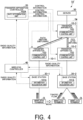
- Fig. 4 is a diagram illustrating a modification example of the mobile communication system 1A of the first embodiment.
- the radio quality information may be supplied to the transfer apparatus controller 20 via an apparatus other than the base station 30, as illustrated in Fig. 4 .
- the wireless controller 40 may be configured to collect radio quality information from the plurality of base stations 30 and supply the collected radio quality information of the plurality of base stations 30 to the transfer apparatus controller 20.
- the example of Fig. 4 shows a case in which the wireless terminal CL before a movement is accommodated in the base station 30 different from that before the movement, after the movement.
- the wireless terminal CL is accommodated in the base station 30-1 at a position before the movement, and is accommodated in the base station 30-2 at a position after the movement.
- the transfer apparatus controller 20 instructs the transfer apparatuses 10-1 and 10-2, which accommodate the base stations 30-1 and 30-2, and the transfer apparatus 10-3, which is located above these, to perform path switching according to a movement of the wireless terminal CL. This makes it possible for the wireless terminal CL to continue communication with the server SV even when the base station 30 accommodating the wireless terminal CL is changed.
- the wireless controller 40 collects the radio quality information from the base stations 30-1 and 30-2 in addition to control of the base stations 30-1 and 30-2, and supplies the collected radio quality information to the transfer apparatus controller 20.
- the transfer apparatus controller 20 determines the shaping rate to be applied to the transfer apparatus 10 (for example, the transfer apparatuses 10-1 and 10-3) on a communication path before the wireless terminal CL moves, on the basis of the radio quality information acquired from the base station 30-1, and determines the shaping rate to be applied to the transfer apparatus 10 (for example, the transfer apparatuses 10-2 and 10-3) on the communication path after the wireless terminal CL moves, on the basis of the radio quality information acquired from the base station 30-2.
- the mobile communication system 1A' according to the present modification example appropriately updates the shaping rate for each traffic flow with respect to the plurality of transfer apparatuses 10 appropriately forming the transfer apparatus network TN according to the movement of the wireless terminal CL.
- the configuration in which the transfer apparatus controller 20 determines the shaping rate of the transfer apparatus 10 for each traffic flow on the basis of the radio quality information is also applicable to communication systems other than the mobile communication system.
- the base station 30 is replaced with a wireless AP, it is possible to suppress delay jitter in the wireless LAN system by acquiring radio quality information for wireless communication between the wireless AP and the wireless terminal CL connected to the wireless AP.
- Fig. 5 is a diagram illustrating a system configuration example of a mobile communication system 1B of the second embodiment.
- the base station 30 includes one or more distributed stations 31A and a central station 32, and the one or more transfer apparatuses 10 differs from the mobile communication system 1A of the first embodiment in that the one or more transfer apparatuses 10 transfers communication between one or more distributed stations 31A and the central station 32.
- Other configurations of the mobile communication system 1B are the same as those of the mobile communication system 1A of the first embodiment. Therefore, here, the same configurations as in the mobile communication system 1A of the first embodiment are denoted by the same reference signs as in Fig. 2 , and description thereof will be omitted.
- the one or more distributed stations 31A and the central station 32 are configured using, for example, a processor such as a CPU, a memory, and a communication interface, like the one or more transfer apparatuses 10 and the transfer apparatus controller 20 included in the mobile communication system 1B.
- a processor such as a CPU, a memory, and a communication interface, like the one or more transfer apparatuses 10 and the transfer apparatus controller 20 included in the mobile communication system 1B.
- Each of the one or more distributed stations 31A and the central station 32 functions as a communication apparatus including a control unit by the processor executing a program.
- the control unit provides respective functions for causing the communication apparatus to function as the distributed station 31A or the central station 32. All or some of the respective functions of the control unit may be realized using hardware such as an ASIC, a PLD, an FPGA, or the like.
- the above program may be recorded on a computer-readable recording medium.
- the computer-readable recording medium includes, for example, a portable medium such as a flexible disk, a magneto-optical disc, a ROM, a CD-ROM, a semiconductor storage apparatus (such as an SSD), or a storage apparatus such as a hard disk or a semiconductor storage apparatus built into a computer system.
- the above program may be transmitted via a telecommunication line.
- the one or more distributed stations 31 and the central station 32 in the second embodiment are one or more distributed units (DUs) and central units (CUs) in a mobile communication system.
- a section between the CU and the DU in which the transfer apparatus 10 is installed is called a mobile midhaul (MMH).
- the one or more distributed stations 31 and the central station 32 in the second embodiment may be one or more radio units (RUs) and DUs in the mobile communication system.
- a section between the DU and the RU in which the transfer apparatus 10 is installed is called a mobile fronthaul (MFH).
- the information acquisition unit 101A is included in a control unit of the distributed station 31A
- the rate determination unit 102A is included in a control unit of the transfer apparatus controller 20
- the communication control unit 103 is included in a control unit of the transfer apparatus 10.
- the information acquisition unit 101A acquires radio quality information on wireless communication between one or more distributed stations 31A and the one or more wireless terminals CL as the wireless communication information, and transmits the acquired radio quality information to the transfer apparatus controller 20.
- the radio quality information includes information on communication quality for each traffic flow in wireless communication between the base station 30 and the wireless terminal CL, and information indicating a priority of each traffic flow.
- the rate determination unit 102A collects the radio quality information acquired by each of the one or more information acquisition units 101A, and determines the shaping rate for each traffic flow on the basis of the collected radio quality information.
- the rate determination unit 102A considers the priority of each traffic flow in the range in which a predetermined delay requirement is satisfied, and then, determines the shaping rate for each traffic flow so that the delay jitter in the base station 30 is mitigated on the upper side with respect to the base station 30.
- the rate determination unit 102A notifies the communication control unit 103 of the transfer apparatus 10 of the determined shaping rate.
- the communication control unit 103 executes the traffic shaping of its own apparatus on the basis of the shaping rate notified from the rate determination unit 102A of the transfer apparatus controller 20.
- the transfer apparatus 10 performs shaping using the shaping rate determined on the basis of the radio quality information on the wireless communication between the one or more wireless terminals CL and the one or more distributed stations 31A so that it is possible to suppress propagation of the delay jitter generated at a point in time of output of the distributed station 31A to the upper side in the related art.
- the radio quality information may be supplied to the transfer apparatus controller 20 via another apparatus other than the base station 30.
- the wireless controller may be configured to collect the radio quality information from the plurality of base stations 30 and supply the collected radio quality information of the plurality of base stations 30 to the transfer apparatus controller 20.
- the configuration in which the transfer apparatus controller 20 determines the shaping rate of the transfer apparatus 10 for each traffic flow on the basis of the radio quality information is also applicable to communication systems other than the mobile communication system.
- the one or more distributed stations 31A and the central station 32 in the second embodiment are replaced with a wireless AP and a wireless LAN controller in a wireless LAN system, it is possible to suppress delay jitter in the wireless LAN system by acquiring radio quality information for wireless communication between the wireless AP and the wireless terminal CL connected to the wireless AP.
- each transfer apparatus 10 includes the communication control unit 103, and the transfer apparatus controller 20 includes the rate determination unit 102A, but the present invention is not limited thereto.
- the communication control unit and the rate determination unit are included in the distributed station 31A, and the distributed station 31A, rather than the transfer apparatus 10, performs shaping may be adopted.
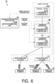
- Fig. 6 is a diagram illustrating a system configuration example of a mobile communication system 1C of a third embodiment.
- a base station 30 includes one or more distributed stations 31 and a central station 32A
- the one or more transfer apparatuses 10 differs from the mobile communication system 1A of the first embodiment in that the one or more transfer apparatuses 10 transfer communication between one or more distributed stations 31 and the central station 32A.
- the mobile communication system 1C differs from the mobile communication system 1B of the second embodiment in that the central station 32A includes an information acquisition unit 101B (information acquirer) and the distributed station 31 does not include an information acquisition unit.
- Other configurations of the mobile communication system 1C are the same as those of the mobile communication system 1A of the first embodiment. Therefore, here, the same configurations as in the mobile communication system 1A of the first embodiment are denoted by the same reference signs as in Fig. 2 , and description thereof will be omitted.
- the one or more distributed stations 31 and the central station 32A are configured using, for example, a processor such as a CPU, a memory, and a communication interface, like the one or more transfer apparatuses 10 and the transfer apparatus controller 20 included in the mobile communication system 1C.
- a processor such as a CPU, a memory, and a communication interface, like the one or more transfer apparatuses 10 and the transfer apparatus controller 20 included in the mobile communication system 1C.
- Each of the one or more distributed stations 31 and the central station 32A functions as a communication apparatus including a control unit by the processor executing a program.
- the control unit provides respective functions for causing the communication apparatus to function as the distributed station 31 or the central station 32A. All or some of the respective functions of the control unit may be realized using hardware such as an ASIC, a PLD, an FPGA, or the like.
- the above program may be recorded on a computer-readable recording medium.
- the computer-readable recording medium includes a portable medium such as a flexible disk, a magneto-optical disc, a ROM, a CD-ROM, a semiconductor storage apparatus (such as an SSD), or a storage apparatus such as a hard disk or a semiconductor storage apparatus built into a computer system.
- the above program may be transmitted via a telecommunication line.
- the one or more distributed stations 31 and the central station 32A in the third embodiment are one or more DUs and a CU in a mobile communication system.
- a section between the CU and the DU in which the transfer apparatus 10 is installed is called an MMH.
- the one or more distributed stations 31 and the central station 32A in the second embodiment may be one or more RUs and DUs in the mobile communication system.
- a section between the DU and the RU in which the transfer apparatus 10 is installed is called a mobile fronthaul (MFH).
- MMH mobile fronthaul
- the information acquisition unit 101B is included in a control unit of the central station 32A
- the rate determination unit 102B is included in a control unit of the transfer apparatus controller 20
- the communication control unit 103 is included in a control unit of the transfer apparatus 10.
- the information acquisition unit 101B acquires the radio quality information on the wireless communication between the one or more distributed stations 31 and the one or more wireless terminals CL as the wireless communication information, and transmits the acquired radio quality information to the transfer apparatus controller 20.
- the radio quality information includes information on communication quality for each traffic flow in wireless communication between the base station 30 and the wireless terminal CL, and information indicating a priority of each traffic flow.
- the communication control unit 103 executes the traffic shaping of its own apparatus on the basis of the shaping rate notified from the rate determination unit 102B of the transfer apparatus controller 20.
- the transfer apparatus 10 performs shaping using the shaping rate determined on the basis of the radio quality information on the wireless communication between the one or more wireless terminals CL and the one or more distributed stations 31, so that it is possible to suppress propagation of the delay jitter generated at a point in time of output of the distributed station 31 to the upper side in the related art.
- the radio quality information may be supplied to the transfer apparatus controller 20 via another apparatus other than the base station 30.
- the wireless controller may be configured to collect the radio quality information from the plurality of base stations 30 and supply the collected radio quality information of the plurality of base stations 30 to the transfer apparatus controller 20.
- the configuration in which the transfer apparatus controller 20 determines the shaping rate of the transfer apparatus 10 for each traffic flow on the basis of the radio quality information is also applicable to communication systems other than the mobile communication system.
- the one or more distributed stations 31 and the central station 32Ain the third embodiment are replaced with a wireless AP and a wireless LAN controller in a wireless LAN system, it is possible to suppress delay jitter in the wireless LAN system by acquiring radio quality information for wireless communication between the wireless AP and the wireless terminal CL connected to the wireless AP.
- each transfer apparatus 10 includes the communication control unit 103, and the transfer apparatus controller 20 includes the rate determination unit 102B, but the present invention is not limited thereto.
- the distributed station 31 includes the communication control unit and the rate determination unit, and the distributed station 31 rather than the transfer apparatus 10 performs shaping may be adopted.
- Fig. 7 is a diagram illustrating a system configuration example of a mobile communication system 1D of the fourth embodiment.
- the mobile communication system 1D differs from the mobile communication system 1A of the first embodiment in that a base station 30 includes one or more distributed stations 31A and a central station 32A, and the one or more transfer apparatuses 10 transfer communication between one or more distributed stations 31A and the central station 32A.
- the mobile communication system 1D differs from the mobile communication system 1B of the second embodiment in that not only the distributed station 31A includes the information acquisition unit 101A, but also the central station 32Aincludes the information acquisition unit 101B.
- Other configurations of the mobile communication system 1D are the same as those of the mobile communication system 1A of the first embodiment. Therefore, here, the same configurations as in the mobile communication system 1A of the first embodiment are denoted by the same reference signs as in Fig. 2 , and description thereof will be omitted.
- the one or more distributed stations 31A and the central station 32A are configured using, for example, a processor such as a CPU, a memory, and a communication interface, like the one or more transfer apparatuses 10 and the transfer apparatus controller 20 included in the mobile communication system 1D.
- a processor such as a CPU, a memory, and a communication interface, like the one or more transfer apparatuses 10 and the transfer apparatus controller 20 included in the mobile communication system 1D.
- Each of the one or more distributed stations 31A and the central station 32A functions as a communication apparatus including a control unit by the processor executing a program.
- the control unit provides respective functions for causing the communication apparatus to function as the distributed station 31A or the central station 32A. All or some of the respective functions of the control unit may be realized using hardware such as an ASIC, a PLD, an FPGA, or the like.
- the above program may be recorded on a computer-readable recording medium.
- the computer-readable recording medium includes a portable medium such as a flexible disk, a magneto-optical disc, a ROM, a CD-ROM, a semiconductor storage apparatus (such as an SSD), or a storage apparatus such as a hard disk or a semiconductor storage apparatus built into a computer system.
- the above program may be transmitted via a telecommunication line.
- the one or more distributed stations 31A and the central station 32A in the fourth embodiment are one or more DUs and a CU in a mobile communication system.
- a section between the CU and the DU in which the transfer apparatus 10 is installed is called an MMH.
- the one or more distributed stations 31A and the central station 32A in the fourth embodiment may be one or more RUs and DUs in the mobile communication system.
- a section between the DU and the RU in which the transfer apparatus 10 is installed is called a mobile fronthaul (MFH).
- MMH mobile fronthaul
- the information acquisition unit 101A is included in a control unit of the distributed station 31A
- the information acquisition unit 101B is included in a control unit of the central station 32A
- the rate determination unit 102C is included in a control unit of the transfer apparatus controller 20
- the communication control unit 103 is included in a control unit of the transfer apparatus 10.
- the information acquisition unit 101A and the information acquisition unit 101B acquire the radio quality information on the wireless communication between the one or more distributed stations 31 and the one or more wireless terminals CL as the wireless communication information, and transmit the acquired radio quality information to the transfer apparatus controller 20.
- the radio quality information includes information on communication quality for each traffic flow in wireless communication between the base station 30 and the wireless terminal CL, and information indicating a priority of each traffic flow.
- the rate determination unit 102C (rate determiner) collects the radio quality information acquired by each of the one or more information acquisition units 101A and the information acquisition unit 101B, and determines the shaping rate for each traffic flow on the basis of the collected radio quality information.
- the rate determination unit 102C considers the priority of each traffic flow in the range in which a predetermined delay requirement is satisfied, and then, determines the shaping rate for each traffic flow so that the delay jitter in the base station 30 is mitigated on the upper side with respect to the base station 30.
- the rate determination unit 102C notifies the communication control unit 103 of the transfer apparatus 10 of the determined shaping rate.
- the communication control unit 103 executes the traffic shaping of its own apparatus on the basis of the shaping rate notified from the rate determination unit 102C of the transfer apparatus controller 20.
- the transfer apparatus 10 performs shaping using the shaping rate determined on the basis of the radio quality information on the wireless communication between the one or more wireless terminals CL and the one or more distributed stations 31A so that it is possible to suppress propagation of the delay jitter generated at a point in time of output of the distributed station 31A to the upper side in the related art.
- the radio quality information may be supplied to the transfer apparatus controller 20 via another apparatus other than the base station 30.
- the wireless controller may be configured to collect the radio quality information from the plurality of base stations 30 and supply the collected radio quality information of the plurality of base stations 30 to the transfer apparatus controller 20.
- the configuration in which the transfer apparatus controller 20 determines the shaping rate of the transfer apparatus 10 for each traffic flow on the basis of the radio quality information is also applicable to communication systems other than the mobile communication system.
- the one or more distributed stations 31A and the central station 32A in the fourth embodiment are replaced with a wireless AP and a wireless LAN controller in a wireless LAN system, it is possible to suppress delay jitter in the wireless LAN system by acquiring radio quality information for wireless communication between the wireless AP and the wireless terminal CL connected to the wireless AP.
- each transfer apparatus 10 includes the communication control unit 103, and the transfer apparatus controller 20 includes the rate determination unit 102C has been adopted
- the present invention is not limited thereto.
- a form in which the communication control unit and the rate determination unit are included in the distributed station 31A, and the distributed station 31A, rather than the transfer apparatus 10, performs shaping may be adopted.
- the communication system includes one or more base stations that accommodate wireless terminals, one or more transfer apparatuses that transfer uplink communication of the wireless terminal received via the base station to the upper side, and a transfer apparatus controller that controls the one or more transfer apparatuses.
- the communication systems are the mobile communication systems 1A, 1A', 1B, 1C, and 1D in the embodiment
- the wireless terminal is the wireless terminal CL in the embodiment
- the base stations are the base stations 30, 30-1, and 30-2 in the embodiment
- the transfer apparatus controller is the transfer apparatus controller 20 in the embodiment.
- the communication system includes an information acquisition unit, a rate determination unit, and a communication control unit.
- the information acquisition units are the information acquisition units 101A and 101B in the embodiment
- the rate determination units are the rate determination units 102A and 102B in the embodiment
- the communication control unit is the communication control unit 103 in the embodiment.
- the information acquisition unit acquires information on wireless communication between the base station and the wireless terminal for each traffic flow.
- the rate determination unit determines the shaping rate for the traffic shaping for each traffic flow, so that the delay jitter in the base station is mitigated on the upper side with respect to the base station, on the basis of the information on the wireless communication for each traffic flow.
- the communication control unit executes the traffic shaping on the upper side with respect to the base station on the basis of the shaping rate determined by the rate determination unit.
- the information on the wireless communication is radio quality information and the wireless communication information in the embodiment.
- the information acquisition unit may acquire radio quality information on wireless communication between the base station and the wireless terminal for each traffic flow
- the rate determination unit may determine the shaping rate for each traffic flow on the basis of association information indicating association between the radio quality information and the shaping rate, and the radio quality information acquired from the base station
- the communication control unit may execute the traffic shaping at the shaping rate determined by the rate determination unit.
- the base station may include a distributed station and a central station, the information acquisition unit may acquire radio quality information on wireless communication between the distributed station and the wireless terminal for each traffic flow, the rate determination unit may determine the shaping rate for each traffic flow on the basis of association information indicating association between the radio quality information and the shaping rate, and the radio quality information acquired from the distributed station, and the communication control unit may execute the traffic shaping at the shaping rate determined by the rate determination unit.
- the distributed stations are the distributed stations 31 and 31A in the embodiment
- the central stations are the central stations 32 and 32A in the embodiment
- the association information is the association table in which the appropriate shaping rate candidates determined according to the value of the 5QI in advance in the embodiment are associated with the value of the 5QI.
- the base station may include the distributed station and the central station, the information acquisition unit may acquire radio quality information on wireless communication between the distributed station and the wireless terminal for each traffic flow, the rate determination unit may determine the shaping rate for each traffic flow on the basis of association information indicating association between the radio quality information and the shaping rate, and the radio quality information acquired from the central station, and the communication control unit may execute the traffic shaping at the shaping rate determined by the rate determination unit.
- the base station may include a distributed station and a central station
- the information acquisition unit may acquire radio quality information on wireless communication between the distributed station and the wireless terminal for each traffic flow
- the rate determination unit may determine the shaping rate for each traffic flow on the basis of association information indicating association between the radio quality information and the shaping rate, and the radio quality information acquired from the distributed station and the central station
- the communication control unit may execute the traffic shaping at the shaping rate determined by the rate determination unit.
- the radio quality information may include information indicating a priority of the traffic flow, and the rate determination unit may determine the shaping rate for each traffic flow while performing priority control of uplink communication for each traffic flow on the basis of the priority.
- the present invention is applicable to a communication system accommodating wireless terminals, and a communication control method.
Landscapes
- Engineering & Computer Science (AREA)
- Computer Networks & Wireless Communication (AREA)
- Signal Processing (AREA)
- Mobile Radio Communication Systems (AREA)
Abstract
Description
- The present invention relates to technology of a communication system that accommodates wireless terminals, and a communication control apparatus.
This application claims priority on the basis ofPCT/JP2021/29119 filed on August 5, 2021 - In the related art, there is a mobile communication system that performs retransmission control such as hybrid automatic repeat request (hybrid ARQ). In such a mobile communication system, in order to maintain an order of the signals when an order of a successfully received signal and a signal requiring retransmission is changed in an uplink, signals are buffered in a base station (see, for example, NPL 1 to NPL 5).
-
- [NPL 1] "3GPP TS 38.322 V16.2.0", 3GPP, 2020.
- [NPL 2] "3GPP TS 23.501 V17.0.0", 3GPP, 2021.
- [NPL 3] "3GPP TS 28.552 V17.3.1", 3GPP, 2021.
- [NPL 4] "3GPP TS 38.321 V16.4.0", 3GPP, 2021.
- [NPL 5] "3GPP TS 38.211 V16.5.0", 3GPP, 2021.
-
Fig. 8 is a diagram illustrating a configuration example of amobile communication system 90 according to the related art. Themobile communication system 90 includes, for example, aserver 91, one ormore transfer apparatuses 92, atransfer apparatus controller 93, and abase station 94. Theserver 91 is an apparatus that communicates with thewireless terminal 95. The one ormore transfer apparatuses 92 are apparatuses that constitute atransfer apparatus network 96 and transfer signals exchanged between theserver 91 and thewireless terminal 95. Thetransfer apparatus controller 93 is an apparatus that controls the one ormore transfer apparatuses 92 by transmitting a control signal. Thebase station 94 is an apparatus that communicates with thewireless terminal 95, transmits a signal transferred from thetransfer apparatus 92 to thewireless terminal 95, and transfers a signal received from thewireless terminal 95 to thetransfer apparatus 92. - However, in the related art described above, a signal successfully received from the
wireless terminal 95 is immediately output from thebase station 94 to thetransfer apparatus 92 on the upper, whereas a retransmitted signal or a signal buffered to hold an order is output from thebase station 94 with a delay. For this reason, intervals at which signals are output from thebase station 94 may not be uniform, and delay jitter may be generated on the upper side with respect to thebase station 94. - Further,
Fig. 9 is a diagram illustrating a configuration example of amobile communication system 90a according to the related art. Themobile communication system 90a includes, for example, aserver 91a, one ormore transfer apparatuses 92a, atransfer apparatus controller 93a, and abase station 94a. Theserver 91a is an apparatus that communicates with each of one or morewireless terminals 95a. The one ormore transfer apparatuses 92a constitute atransfer apparatus network 96a and are apparatuses that transfer a signal exchanged between theserver 91a and eachwireless terminal 95a. Thetransfer apparatus controller 93a is an apparatus that controls the one ormore transfer apparatuses 92a by transmitting a control signal. Thebase station 94a is an apparatus that communicates with each of the one or morewireless terminals 95a, transmits a signal transferred from thetransfer apparatus 92a to each of the one or morewireless terminals 95a, and transfers a signal received from each of the one or morewireless terminals 95a to thetransfer apparatus 92a. Thewireless terminal 95a has one or more traffic flows. - However, as in the related art described above, when a plurality of
base stations 94a are connected to onetransfer apparatus 92a, when a plurality ofwireless terminals 95a are connected to onebase station 94a, or when onewireless terminal 95a includes a plurality of traffic flows, different types of traffic are mixed and output from thebase station 94a. Therefore, in the case of themobile communication system 90a ofFig. 9 , there is a problem that delay jitter for each traffic flow which should be seen in more detail as the quality of service may become larger, as compared with a case of themobile communication system 90 ofFig. 8 . - In view of the above circumstances, an object of the present invention is to provide a technology capable of suppressing delay jitter.
- An aspect of the present invention is a communication system including one or more base stations configured to accommodate wireless terminals, one or more transfer apparatuses configured to transfer uplink communication of the wireless terminal received via the base station to an upper side, and a transfer apparatus controller configured to control the one or more transfer apparatuses, the communication system including: an information acquisition unit configured to acquire information on wireless communication between the base station and the wireless terminal for each traffic flow; a rate determination unit configured to determine a shaping rate of traffic shaping for each traffic flow, so that delay jitter in the base station is mitigated on an upper side with respect to the base station, on the basis of the information on the wireless communication for each traffic flow; and a communication control unit configured to execute the traffic shaping on the upper side with respect to the base station on the basis of the shaping rate determined by the rate determination unit.
- An aspect of the present invention is, in a communication system including one or more base stations configured to accommodate wireless terminals, one or more transfer apparatuses configured to transfer uplink communication of the wireless terminal received via the base station to an upper side, and a transfer apparatus controller configured to control the one or more transfer apparatuses, a communication control method including: an information acquisition step of acquiring information on wireless communication between the base station and the wireless terminal for each traffic flow; a rate determination unit of determining a shaping rate of traffic shaping for each traffic flow, so that delay jitter in the base station is mitigated on an upper side with respect to the base station, on the basis of the information on the wireless communication for each traffic flow; and a communication control step of executing the traffic shaping on the upper side with respect to the base station on the basis of the shaping rate determined in the rate determination step.
- According to the present invention, it is possible to suppress the occurrence of delay jitter.
-
- [
Fig. 1 ]
Fig. 1 is a diagram illustrating a system configuration example of a mobile communication system according to a first embodiment. - [
Fig. 2 ]
Fig. 2 is a diagram illustrating a specific example of a functional configuration of the mobile communication system according to the first embodiment. - [
Fig. 3 ]
Fig. 3 is an image diagram illustrating that an effect of suppression of delay jitter through shaping of a transfer apparatus is obtained in the mobile communication system of the first embodiment. - [
Fig. 4 ]
Fig. 4 is a diagram illustrating a modification example of the mobile communication system of the first embodiment. - [
Fig. 5 ]
Fig. 5 is a diagram illustrating a system configuration example of a mobile communication system according to a second embodiment. - [
Fig. 6 ]
Fig. 6 is a diagram illustrating a system configuration example of a mobile communication system according to a third embodiment. - [
Fig. 7 ]
Fig. 7 is a diagram illustrating a system configuration example of a mobile communication system according to a fourth embodiment. - [
Fig. 8 ]
Fig. 8 is a diagram illustrating a configuration example of a mobile communication system according to the related art. - [
Fig. 9 ]
Fig. 9 is a diagram illustrating a configuration example of a mobile communication system according to the related art; - Embodiments of the present invention will be described in detail with reference to the drawings.
-
Fig. 1 is a diagram illustrating a system configuration example of amobile communication system 1A of the first embodiment. Themobile communication system 1A includes, for example, one ormore transfer apparatuses 10, atransfer apparatus controller 20, and one ormore base stations 30. A server SV is an apparatus that communicates with each of one or more wireless terminals CL. - The one or
more transfer apparatuses 10 constitute a transfer apparatus network TN, and transfer a signal exchanged between the server SV and the one or more wireless terminals CL. Thetransfer apparatus controller 20 is an apparatus that controls the one ormore transfer apparatuses 10 by transmitting a control signal. Thebase station 30 is an apparatus that communicates with each of the one or more wireless terminals CL, transmits a signal transferred from thetransfer apparatus 10 to the wireless terminal CL, and transfers a signal received from the wireless terminals CL to thetransfer apparatus 10. Each of the one or more wireless terminals CL has one or more traffic flows. Thetransfer apparatus controller 20 is communicatively connected to each of the one ormore transfer apparatuses 10 and thebase station 30. - The one or
more transfer apparatuses 10, thetransfer apparatus controller 20, and thebase station 30 included in themobile communication system 1A are configured using, for example, a processor such as a central processing unit (CPU), a memory, and a communication interface. Each of the one ormore transfer apparatuses 10, thetransfer apparatus controller 20, and thebase station 30 functions as a communication apparatus including a control unit by the processor executing a program. - The control unit provides each function for causing the communication apparatus to function as the
transfer apparatus 10, thetransfer apparatus controller 20, or thebase station 30. All or some of respective functions of the control unit may be realized using hardware such as an application specific integrated circuit (ASIC), a programmable logic device (PLD), or a field programmable gate array (FPGA). - The program may be recorded on a computer-readable recording medium. The computer-readable recording medium is a storage apparatus such as a portable medium such as a flexible disk, a magneto-optical disc, a ROM, a CD-ROM, a semiconductor storage apparatus (such as SSD: Solid State Drives), or a hard disk or a semiconductor storage apparatus built into a computer system. The above program may be transmitted via a telecommunication line.
-
Fig. 2 is a diagram illustrating a specific example of a functional configuration of themobile communication system 1A of the first embodiment. Themobile communication system 1A includes, for example, one or moreinformation acquisition units 101A, arate determination units 102A, and one or morecommunication control units 103. - The
information acquisition unit 101A (information acquirer) acquires information on wireless communication between thebase station 30 and the wireless terminal CL (hereinafter referred to as "wireless communication information"). Therate determination unit 102A collects the wireless communication information acquired by each of one or moreinformation acquisition units 101A, and determines, for each traffic flow, a shaping rate of traffic shaping so that delay jitter in thebase station 30 is mitigated in the upper side with respect to thebase station 30, on the basis of the collected wireless communication information. The communication control unit 103 (communication controller) executes the traffic shaping on the upper side with respect to thebase station 30 on the basis of the shaping rate determined by therate determination unit 102A. - Specifically, in the
mobile communication system 1A of the first embodiment, theinformation acquisition unit 101A is included in a control unit of thebase station 30, therate determination unit 102A is included in a control unit of thetransfer apparatus controller 20, and thecommunication control unit 103 is included in a control unit of thetransfer apparatus 10. - In this case, one or more
information acquisition units 101A acquire information including control information on the quality of wireless communication between thebase station 30 and the wireless terminal CL (hereinafter referred to as "the radio quality information"), as the wireless communication information, and transmit the acquired radio quality information to thetransfer apparatus controller 20. The radio quality information includes information on communication quality for each traffic flow in wireless communication between thebase station 30 and the wireless terminal CL, and information indicating a priority of each traffic flow. - The
rate determination unit 102A (rate determiner) collects the radio quality information acquired by each of the one or moreinformation acquisition units 101A, and determines the shaping rate for each traffic flow on the basis of the collected radio quality information. Here, therate determination unit 102A considers the priority of each traffic flow in a range in which a predetermined delay requirement is satisfied, and then, determines the shaping rate of the traffic shaping for each traffic flow so that the delay jitter in thebase station 30 is mitigated on the upper side with respect to thebase station 30. Therate determination unit 102A notifies thecommunication control unit 103 of thetransfer apparatus 10 of the determined shaping rate. - In the one or
more transfer apparatuses 10, thecommunication control unit 103 executes the traffic shaping of its own apparatus on the basis of the shaping rate notified from therate determination unit 102A of thetransfer apparatus controller 20. - Here, the radio quality information acquired as the wireless communication information is, for example, 5G QoS indicator (5QI) assigned to a header of an N3 interface signal in fifth generation (5G) mobile communication, or a PDCP SDU data volume for each 5QI.
- For example, the
rate determination unit 102A of thetransfer apparatus controller 20 stores in advance an association table (association information) in which appropriate shaping rate candidates determined according to a value of the 5QI in advance are associated with the value of the 5QI, and the shaping rate associated with the 5QI value (the radio quality information) acquired from thebase station 30 is determined as the shaping rate to be applied to thetransfer apparatus 10 in this association table. The appropriate shaping rate is a communication rate that is low enough to narrow the communication band so that the delay jitter in thebase station 30 is mitigated on the upper side with respect to thebase station 30 while maintaining at least a minimum required communication rate. - Alternatively, examples of the radio quality information acquired as the wireless communication information may include a scheduling request, an uplink grant, and a buffer status report, which the
base station 30 receives from the wireless terminal CL, and a radio frame number, subframe number, and slot number at which the base station has received the scheduling request, uplink grant, and buffer status report. - In general, the scheduling request is information that a wireless terminal transmits to a base station to notify of the start of the uplink communication. The uplink grant is information transmitted by a base station in downlink communication in order to notify a wireless terminal of a wireless communication scheme in which uplink communication is permitted or frequency resource allocation, and indirectly shows an amount of data of the uplink communication. The buffer status report is information transmitted by a wireless terminal to notify the base station of how much data is held in the buffer.
- The radio frame number, subframe number, and slot number are numbers on the three-stage data basis transmitted by wireless communication, a radio frame is defined as 10 [ms], a subframe is defined as 1 [ms], and a slot is defined as, for example, a length selected from among a plurality of values such as 1 [ms] and 0.5 [ms], and it is possible to obtain a transmission/reception timing of the wireless communication from these numbers.
- The scheduling request, the uplink grant, and the buffer status report are transmitted in association with a radio frame number, subframe number, and slot number indicating a transmission timing for uplink communication. In this case, the
rate determination unit 102A collects the radio quality information acquired by each of the one or moreinformation acquisition units 101A, and determines an appropriate shaping rate for each traffic flow through calculation on the basis of the collected radio quality information. - Specifically, the
rate determination unit 102A recognizes an amount of data buffered in the wireless terminal CL by the buffer status report received from the wireless terminal CL (hereinafter referred to as "buffer data"), and calculates, as an appropriate shaping rate, a communication rate low enough to narrow a communication band so that the delay jitter in thebase station 30 is mitigated on the upper side with respect to thebase station 30 while maintaining at least a minimum required communication rate for transmission of the buffer data having the amount of data. - More specifically, for example, when the
rate determination unit 102A acquires the scheduling request from theinformation acquisition unit 101A, the shaping rate is initialized, and the radio frame number, subframe number, and slot number associated with the acquired the scheduling request are held. Thereafter, the shaping rate is updated each time therate determination unit 102A acquires the buffer status report from theinformation acquisition unit 101A. - For update of the shaping rate, for example, the shaping rate is determined by adding a cumulative value of an amount of data in uplink communication calculated from one or more uplink grants acquired from the
information acquisition unit 101A by therate determination unit 102A between a radio frame number, subframe number, and slot number associated with the scheduling request and a radio frame number, subframe number, and slot number associated with the buffer status report, to an amount of data held by the wireless terminal notified by the buffer status report, and performing division at time intervals calculated from the radio frame number, subframe number, and slot number associated with the scheduling request and the radio frame number, subframe number, and slot number associated with the buffer status report. - The
rate determination unit 102A is configured to collect information on a state of the transfer apparatus network TN (hereinafter referred to as "state information") from thetransfer apparatus 10, and calculate the shaping rate to be applied to thetransfer apparatus 10 on the basis of this state information and the radio quality information acquired from thebase station 30. For example, therate determination unit 102A may calculate the shaping rate in consideration of a congestion state of the transfer apparatus network TN recognized on the basis of the state information. - According to the
mobile communication system 1A of the first embodiment configured as described above, thetransfer apparatus 10 performs shaping at the shaping rate determined on the basis of the radio quality information on wireless communication between the wireless terminal CL and thebase station 30, so that it is possible to suppress propagation of the delay jitter generated at a point in time of output of the base station to the upper side in the related art. -
Fig. 3 is an image diagram illustrating that an effect of suppression of the delay jitter through shaping of thetransfer apparatus 10 is obtained in themobile communication system 1A of the first embodiment. InFig. 3 , a diagram on the left side illustrates a situation in which the delay jitter propagates to the upper side according to the related art, and a diagram on the right side illustrates a situation in which the delay jitter is suppressed by themobile communication system 1A of the present embodiment. - A flow (steps S1 to S31) from the wireless terminal transmitting a frame to the base station receiving the frame and transmitting the frame to the transfer apparatus is the same between the related art and the present embodiment. Hereinafter, a flow from steps S1 to S31 that is the same between the related art and the present embodiment, will be described first.
- First, the wireless terminal CL transmits first to fifth frames to the
base station 30 at equal intervals in a first traffic flow (hereinafter referred to as "traffic flow 1") (step S1). Rectangles withnumbers 1 to 5 in the figure represent the corresponding first to fifth frames. Further, the wireless terminal CL transmits frames a to e to thebase station 30 at equal intervals in a second traffic flow (hereinafter referred to as "traffic flow 2") (step S1). Rectangles with alphabetic characters a to e in the figure represent corresponding frames a to e. The first to fifth frames and the frames a to e are frequency-multiplexed and transmitted simultaneously. - Next, the
base station 30 receives the first to fifth frames transmitted by the wireless terminal CL. Specifically, here, the following steps S21 and S22 are assumed. Step S21 shows a situation in which thebase station 30 normally receives the first, second and fifth frames, but fails to receive the third and fourth frames, which is a situation in which the wireless terminal CL is requested to perform a retransmission of the third and fourth frames. Step S22 shows a situation in which thebase station 30 normally receives the retransmitted third and fourth frames. - Further, the
base station 30 receives the frames a to e transmitted by the wireless terminal CL. Specifically, here, the following step S23 is assumed. Step S23 shows a situation in which thebase station 30 has normally received all the frames a to e without making a retransmission request. - In this case, the
base station 30 immediately transmits, to thetransfer apparatus 10, the first and second frames among the first, second, and fifth frames that have been normally received. On the other hand, since thebase station 30 holds an order of the frames for the fifth frame, it is necessary to hold the order until the third and fourth frames are normally received by the retransmission. - Next, the
base station 30 transmits the frames a to e at an available timing. Step S31 shows a situation in which thebase station 30 transmits the frames a to d to thetransfer apparatus 10 at equal intervals at an available timing between transmission of the second frame and normal reception of the third frame through retransmission. When the third and fourth frames are normally received by retransmission, thebase station 30 transmits the third to fifth frames to thetransfer apparatus 10 at equal intervals. - Next, the
base station 30 transmits the frame e to the transfer apparatus 10 (step S31). InFig. 3 , description of a situation of frame reception in thetransfer apparatus 10 is omitted. - In a flow (steps S 1 to S31) from the wireless terminal transmitting a frame to the base station receiving the frame and transmitting the frame to the transfer apparatus (steps S1 to S31) illustrated in
Fig. 3 , a transmission interval between the second frame and the third frame is longer than that between other frames, and the delay jitter is generated. Further, in the flow, a transmission interval between the frame d and the frame e is longer than that between other frames, and the delay jitter is generated. - That is, in the flow, frame intervals are not uniform in each of traffic flows 1 and 2, and the delay jitter is generated. As described above, the first to fifth frames and the frames a to e are transmitted and received in the same flow in the communication system of the related art so far.
- Thereafter, in the communication system of the related art, the first to fifth frames and the frames a to e are transferred to the upper side by the one or more transfer apparatuses with the delay jitter generated in the base station maintained (step S41).
- In contrast to the related art described above, in the
mobile communication system 1A of the present embodiment, the one ormore transfer apparatuses 10 considers the priority of each traffic flow in the range in which a predetermined delay requirement is satisfied using thetransfer apparatus controller 20, and then, transfers the first to fifth frames and the frames a to e while performing the traffic shaping at the shaping rate determined to mitigate the delay jitter (step S42). - Such a configuration is provided so that the
mobile communication system 1A of the present embodiment can mitigate the delay jitter generated in thebase station 30 on the higher side than thebase station 30.Fig. 3 illustrates a case in which the one ormore transfer apparatuses 10 recognize traffic flow 2 (the frames a to e) as having a higher priority using thetransfer apparatus controller 20, and the one ormore transfer apparatuses 10 changes an order of frames on the basis of the priority, and performs the traffic shaping so that the frame intervals are also uniform. - That is, the frame a is preferentially transmitted over the first frame, as shown in step S42 of
Fig. 3 . Further, as shown in step S42 ofFig. 3 , all of the first to fifth frames and the frames a to e are transmitted at equal intervals (in every other frame). - In the
mobile communication system 1A of the first embodiment, the configuration in which thetransfer apparatus controller 20 determines the shaping rate of thetransfer apparatus 10 for each traffic flow on the basis of the radio quality information is also applicable to communication systems other than the mobile communication system. For example, when thebase station 30 is replaced with a wireless local area network (LAN) access point (hereinafter referred to as "wireless AP"), it is possible to suppress delay jitter in the wireless LAN system by acquiring radio quality information for wireless communication between the wireless AP and the wireless terminal CL connected to the wireless AP. - In the present embodiment, each
transfer apparatus 10 includes thecommunication control unit 103, and thetransfer apparatus controller 20 includes therate determination unit 102A, but the present invention is not limited thereto. For example, a form in which thebase station 30 includes the communication control unit and the rate determination unit, and thebase station 30 rather than thetransfer apparatus 10 performs shaping may be adopted. -
Fig. 4 is a diagram illustrating a modification example of themobile communication system 1A of the first embodiment. Although a case in which thebase station 30 directly supplies the radio quality information to thetransfer apparatus controller 20 has been described in the first embodiment, the radio quality information may be supplied to thetransfer apparatus controller 20 via an apparatus other than thebase station 30, as illustrated inFig. 4 . - For example, in the
mobile communication system 1A' of the modification example, when there are a plurality ofbase stations 30 and there is also awireless controller 40 that controls the plurality ofbase stations 30, thewireless controller 40 may be configured to collect radio quality information from the plurality ofbase stations 30 and supply the collected radio quality information of the plurality ofbase stations 30 to thetransfer apparatus controller 20. - The example of
Fig. 4 shows a case in which the wireless terminal CL before a movement is accommodated in thebase station 30 different from that before the movement, after the movement. Specifically, in the example ofFig. 4 , the wireless terminal CL is accommodated in the base station 30-1 at a position before the movement, and is accommodated in the base station 30-2 at a position after the movement. In this case, thetransfer apparatus controller 20 instructs the transfer apparatuses 10-1 and 10-2, which accommodate the base stations 30-1 and 30-2, and the transfer apparatus 10-3, which is located above these, to perform path switching according to a movement of the wireless terminal CL. This makes it possible for the wireless terminal CL to continue communication with the server SV even when thebase station 30 accommodating the wireless terminal CL is changed. - In this case, the
wireless controller 40 collects the radio quality information from the base stations 30-1 and 30-2 in addition to control of the base stations 30-1 and 30-2, and supplies the collected radio quality information to thetransfer apparatus controller 20. In this case, for example, thetransfer apparatus controller 20 determines the shaping rate to be applied to the transfer apparatus 10 (for example, the transfer apparatuses 10-1 and 10-3) on a communication path before the wireless terminal CL moves, on the basis of the radio quality information acquired from the base station 30-1, and determines the shaping rate to be applied to the transfer apparatus 10 (for example, the transfer apparatuses 10-2 and 10-3) on the communication path after the wireless terminal CL moves, on the basis of the radio quality information acquired from the base station 30-2. With such a configuration, themobile communication system 1A' according to the present modification example appropriately updates the shaping rate for each traffic flow with respect to the plurality oftransfer apparatuses 10 appropriately forming the transfer apparatus network TN according to the movement of the wireless terminal CL. - In the
mobile communication system 1A' of the present modification example, the configuration in which thetransfer apparatus controller 20 determines the shaping rate of thetransfer apparatus 10 for each traffic flow on the basis of the radio quality information is also applicable to communication systems other than the mobile communication system. For example, when thebase station 30 is replaced with a wireless AP, it is possible to suppress delay jitter in the wireless LAN system by acquiring radio quality information for wireless communication between the wireless AP and the wireless terminal CL connected to the wireless AP. -
Fig. 5 is a diagram illustrating a system configuration example of amobile communication system 1B of the second embodiment. In themobile communication system 1B, thebase station 30 includes one or more distributedstations 31A and acentral station 32, and the one ormore transfer apparatuses 10 differs from themobile communication system 1A of the first embodiment in that the one ormore transfer apparatuses 10 transfers communication between one or more distributedstations 31A and thecentral station 32. Other configurations of themobile communication system 1B are the same as those of themobile communication system 1A of the first embodiment. Therefore, here, the same configurations as in themobile communication system 1A of the first embodiment are denoted by the same reference signs as inFig. 2 , and description thereof will be omitted. - The one or more distributed
stations 31A and thecentral station 32 are configured using, for example, a processor such as a CPU, a memory, and a communication interface, like the one ormore transfer apparatuses 10 and thetransfer apparatus controller 20 included in themobile communication system 1B. Each of the one or more distributedstations 31A and thecentral station 32 functions as a communication apparatus including a control unit by the processor executing a program. - The control unit provides respective functions for causing the communication apparatus to function as the distributed
station 31A or thecentral station 32. All or some of the respective functions of the control unit may be realized using hardware such as an ASIC, a PLD, an FPGA, or the like. The above program may be recorded on a computer-readable recording medium. The computer-readable recording medium includes, for example, a portable medium such as a flexible disk, a magneto-optical disc, a ROM, a CD-ROM, a semiconductor storage apparatus (such as an SSD), or a storage apparatus such as a hard disk or a semiconductor storage apparatus built into a computer system. The above program may be transmitted via a telecommunication line. - For example, the one or more distributed
stations 31 and thecentral station 32 in the second embodiment are one or more distributed units (DUs) and central units (CUs) in a mobile communication system. In this case, a section between the CU and the DU in which thetransfer apparatus 10 is installed is called a mobile midhaul (MMH). Further, for example, the one or more distributedstations 31 and thecentral station 32 in the second embodiment may be one or more radio units (RUs) and DUs in the mobile communication system. In this case, a section between the DU and the RU in which thetransfer apparatus 10 is installed is called a mobile fronthaul (MFH). - Specifically, in the
mobile communication system 1B of the second embodiment, theinformation acquisition unit 101A is included in a control unit of the distributedstation 31A, therate determination unit 102A is included in a control unit of thetransfer apparatus controller 20, and thecommunication control unit 103 is included in a control unit of thetransfer apparatus 10. - In this case, the
information acquisition unit 101A acquires radio quality information on wireless communication between one or more distributedstations 31A and the one or more wireless terminals CL as the wireless communication information, and transmits the acquired radio quality information to thetransfer apparatus controller 20. The radio quality information includes information on communication quality for each traffic flow in wireless communication between thebase station 30 and the wireless terminal CL, and information indicating a priority of each traffic flow. - The
rate determination unit 102A collects the radio quality information acquired by each of the one or moreinformation acquisition units 101A, and determines the shaping rate for each traffic flow on the basis of the collected radio quality information. Here, therate determination unit 102A considers the priority of each traffic flow in the range in which a predetermined delay requirement is satisfied, and then, determines the shaping rate for each traffic flow so that the delay jitter in thebase station 30 is mitigated on the upper side with respect to thebase station 30. Therate determination unit 102A notifies thecommunication control unit 103 of thetransfer apparatus 10 of the determined shaping rate. - In the one or
more transfer apparatuses 10, thecommunication control unit 103 executes the traffic shaping of its own apparatus on the basis of the shaping rate notified from therate determination unit 102A of thetransfer apparatus controller 20. - According to the
mobile communication system 1B of the second embodiment configured as described above, thetransfer apparatus 10 performs shaping using the shaping rate determined on the basis of the radio quality information on the wireless communication between the one or more wireless terminals CL and the one or more distributedstations 31A so that it is possible to suppress propagation of the delay jitter generated at a point in time of output of the distributedstation 31A to the upper side in the related art. - In the above embodiment, although the case in which the
base station 30 directly supplies the radio quality information to thetransfer apparatus controller 20 has been described, the radio quality information may be supplied to thetransfer apparatus controller 20 via another apparatus other than thebase station 30. For example, in themobile communication system 1B, when there are the plurality ofbase stations 30 and there is also a wireless controller that controls the plurality ofbase stations 30, the wireless controller may be configured to collect the radio quality information from the plurality ofbase stations 30 and supply the collected radio quality information of the plurality ofbase stations 30 to thetransfer apparatus controller 20. - In the
mobile communication system 1B of the second embodiment, the configuration in which thetransfer apparatus controller 20 determines the shaping rate of thetransfer apparatus 10 for each traffic flow on the basis of the radio quality information is also applicable to communication systems other than the mobile communication system. For example, when the one or more distributedstations 31A and thecentral station 32 in the second embodiment are replaced with a wireless AP and a wireless LAN controller in a wireless LAN system, it is possible to suppress delay jitter in the wireless LAN system by acquiring radio quality information for wireless communication between the wireless AP and the wireless terminal CL connected to the wireless AP. - In the present embodiment, each
transfer apparatus 10 includes thecommunication control unit 103, and thetransfer apparatus controller 20 includes therate determination unit 102A, but the present invention is not limited thereto. For example, a form in which the communication control unit and the rate determination unit are included in the distributedstation 31A, and the distributedstation 31A, rather than thetransfer apparatus 10, performs shaping may be adopted. -
Fig. 6 is a diagram illustrating a system configuration example of amobile communication system 1C of a third embodiment. In themobile communication system 1C, abase station 30 includes one or more distributedstations 31 and acentral station 32A, and the one ormore transfer apparatuses 10 differs from themobile communication system 1A of the first embodiment in that the one ormore transfer apparatuses 10 transfer communication between one or more distributedstations 31 and thecentral station 32A. Further, themobile communication system 1C differs from themobile communication system 1B of the second embodiment in that thecentral station 32A includes aninformation acquisition unit 101B (information acquirer) and the distributedstation 31 does not include an information acquisition unit. Other configurations of themobile communication system 1C are the same as those of themobile communication system 1A of the first embodiment. Therefore, here, the same configurations as in themobile communication system 1A of the first embodiment are denoted by the same reference signs as inFig. 2 , and description thereof will be omitted. - The one or more distributed
stations 31 and thecentral station 32A are configured using, for example, a processor such as a CPU, a memory, and a communication interface, like the one ormore transfer apparatuses 10 and thetransfer apparatus controller 20 included in themobile communication system 1C. Each of the one or more distributedstations 31 and thecentral station 32A functions as a communication apparatus including a control unit by the processor executing a program. - The control unit provides respective functions for causing the communication apparatus to function as the distributed
station 31 or thecentral station 32A. All or some of the respective functions of the control unit may be realized using hardware such as an ASIC, a PLD, an FPGA, or the like. The above program may be recorded on a computer-readable recording medium. The computer-readable recording medium includes a portable medium such as a flexible disk, a magneto-optical disc, a ROM, a CD-ROM, a semiconductor storage apparatus (such as an SSD), or a storage apparatus such as a hard disk or a semiconductor storage apparatus built into a computer system. The above program may be transmitted via a telecommunication line. - For example, the one or more distributed
stations 31 and thecentral station 32A in the third embodiment are one or more DUs and a CU in a mobile communication system. In this case, a section between the CU and the DU in which thetransfer apparatus 10 is installed is called an MMH. Further, for example, the one or more distributedstations 31 and thecentral station 32A in the second embodiment may be one or more RUs and DUs in the mobile communication system. In this case, a section between the DU and the RU in which thetransfer apparatus 10 is installed is called a mobile fronthaul (MFH). - Specifically, in the
mobile communication system 1C of the third embodiment, theinformation acquisition unit 101B is included in a control unit of thecentral station 32A, therate determination unit 102B is included in a control unit of thetransfer apparatus controller 20, and thecommunication control unit 103 is included in a control unit of thetransfer apparatus 10. - In this case, the
information acquisition unit 101B acquires the radio quality information on the wireless communication between the one or more distributedstations 31 and the one or more wireless terminals CL as the wireless communication information, and transmits the acquired radio quality information to thetransfer apparatus controller 20. The radio quality information includes information on communication quality for each traffic flow in wireless communication between thebase station 30 and the wireless terminal CL, and information indicating a priority of each traffic flow. - The
rate determination unit 102B (rate determiner) determines a shaping rate for each traffic flow on the basis of the radio quality information acquired byinformation acquisition unit 101B. Here, therate determination unit 102B considers the priority of each traffic flow in the range in which a predetermined delay requirement is satisfied, and then, determines the shaping rate for each traffic flow so that the delay jitter in thebase station 30 is mitigated on the upper side with respect to thebase station 30. Therate determination unit 102B notifies thecommunication control unit 103 of thetransfer apparatus 10 of the determined shaping rate. - In the one or
more transfer apparatuses 10, thecommunication control unit 103 executes the traffic shaping of its own apparatus on the basis of the shaping rate notified from therate determination unit 102B of thetransfer apparatus controller 20. - According to the
mobile communication system 1C of the third embodiment configured as described above, thetransfer apparatus 10 performs shaping using the shaping rate determined on the basis of the radio quality information on the wireless communication between the one or more wireless terminals CL and the one or more distributedstations 31, so that it is possible to suppress propagation of the delay jitter generated at a point in time of output of the distributedstation 31 to the upper side in the related art. - In the above embodiment, although the case in which the
base station 30 directly supplies the radio quality information to thetransfer apparatus controller 20 has been described, the radio quality information may be supplied to thetransfer apparatus controller 20 via another apparatus other than thebase station 30. For example, in themobile communication system 1C, when there are the plurality ofbase stations 30 and there is also a wireless controller that controls the plurality ofbase stations 30, the wireless controller may be configured to collect the radio quality information from the plurality ofbase stations 30 and supply the collected radio quality information of the plurality ofbase stations 30 to thetransfer apparatus controller 20. - In the
mobile communication system 1C of the third embodiment, the configuration in which thetransfer apparatus controller 20 determines the shaping rate of thetransfer apparatus 10 for each traffic flow on the basis of the radio quality information is also applicable to communication systems other than the mobile communication system. For example, when the one or more distributedstations 31 and the central station 32Ain the third embodiment are replaced with a wireless AP and a wireless LAN controller in a wireless LAN system, it is possible to suppress delay jitter in the wireless LAN system by acquiring radio quality information for wireless communication between the wireless AP and the wireless terminal CL connected to the wireless AP. - In the present embodiment, each
transfer apparatus 10 includes thecommunication control unit 103, and thetransfer apparatus controller 20 includes therate determination unit 102B, but the present invention is not limited thereto. For example, a form in which the distributedstation 31 includes the communication control unit and the rate determination unit, and the distributedstation 31 rather than thetransfer apparatus 10 performs shaping may be adopted. -
Fig. 7 is a diagram illustrating a system configuration example of amobile communication system 1D of the fourth embodiment. Themobile communication system 1D differs from themobile communication system 1A of the first embodiment in that abase station 30 includes one or more distributedstations 31A and acentral station 32A, and the one ormore transfer apparatuses 10 transfer communication between one or more distributedstations 31A and thecentral station 32A. Further, themobile communication system 1D differs from themobile communication system 1B of the second embodiment in that not only the distributedstation 31A includes theinformation acquisition unit 101A, but also the central station 32Aincludes theinformation acquisition unit 101B. Other configurations of themobile communication system 1D are the same as those of themobile communication system 1A of the first embodiment. Therefore, here, the same configurations as in themobile communication system 1A of the first embodiment are denoted by the same reference signs as inFig. 2 , and description thereof will be omitted. - The one or more distributed
stations 31A and thecentral station 32A are configured using, for example, a processor such as a CPU, a memory, and a communication interface, like the one ormore transfer apparatuses 10 and thetransfer apparatus controller 20 included in themobile communication system 1D. Each of the one or more distributedstations 31A and thecentral station 32A functions as a communication apparatus including a control unit by the processor executing a program. - The control unit provides respective functions for causing the communication apparatus to function as the distributed
station 31A or thecentral station 32A. All or some of the respective functions of the control unit may be realized using hardware such as an ASIC, a PLD, an FPGA, or the like. The above program may be recorded on a computer-readable recording medium. The computer-readable recording medium includes a portable medium such as a flexible disk, a magneto-optical disc, a ROM, a CD-ROM, a semiconductor storage apparatus (such as an SSD), or a storage apparatus such as a hard disk or a semiconductor storage apparatus built into a computer system. The above program may be transmitted via a telecommunication line. - For example, the one or more distributed
stations 31A and thecentral station 32A in the fourth embodiment are one or more DUs and a CU in a mobile communication system. In this case, a section between the CU and the DU in which thetransfer apparatus 10 is installed is called an MMH. Further, for example, the one or more distributedstations 31A and thecentral station 32A in the fourth embodiment may be one or more RUs and DUs in the mobile communication system. In this case, a section between the DU and the RU in which thetransfer apparatus 10 is installed is called a mobile fronthaul (MFH). - Specifically, in the
mobile communication system 1D of the fourth embodiment, theinformation acquisition unit 101A is included in a control unit of the distributedstation 31A, theinformation acquisition unit 101B is included in a control unit of thecentral station 32A, therate determination unit 102C is included in a control unit of thetransfer apparatus controller 20, and thecommunication control unit 103 is included in a control unit of thetransfer apparatus 10. - In this case, the
information acquisition unit 101A and theinformation acquisition unit 101B acquire the radio quality information on the wireless communication between the one or more distributedstations 31 and the one or more wireless terminals CL as the wireless communication information, and transmit the acquired radio quality information to thetransfer apparatus controller 20. The radio quality information includes information on communication quality for each traffic flow in wireless communication between thebase station 30 and the wireless terminal CL, and information indicating a priority of each traffic flow. - The
rate determination unit 102C (rate determiner) collects the radio quality information acquired by each of the one or moreinformation acquisition units 101A and theinformation acquisition unit 101B, and determines the shaping rate for each traffic flow on the basis of the collected radio quality information. Here, therate determination unit 102C considers the priority of each traffic flow in the range in which a predetermined delay requirement is satisfied, and then, determines the shaping rate for each traffic flow so that the delay jitter in thebase station 30 is mitigated on the upper side with respect to thebase station 30. Therate determination unit 102C notifies thecommunication control unit 103 of thetransfer apparatus 10 of the determined shaping rate. - In the one or
more transfer apparatuses 10, thecommunication control unit 103 executes the traffic shaping of its own apparatus on the basis of the shaping rate notified from therate determination unit 102C of thetransfer apparatus controller 20. - According to the
mobile communication system 1D of the fourth embodiment configured as described above, thetransfer apparatus 10 performs shaping using the shaping rate determined on the basis of the radio quality information on the wireless communication between the one or more wireless terminals CL and the one or more distributedstations 31A so that it is possible to suppress propagation of the delay jitter generated at a point in time of output of the distributedstation 31A to the upper side in the related art. - In the above embodiment, although the case in which the
base station 30 directly supplies the radio quality information to thetransfer apparatus controller 20 has been described, the radio quality information may be supplied to thetransfer apparatus controller 20 via another apparatus other than thebase station 30. For example, in themobile communication system 1D, when there are the plurality ofbase stations 30 and there is also a wireless controller that controls the plurality ofbase stations 30, the wireless controller may be configured to collect the radio quality information from the plurality ofbase stations 30 and supply the collected radio quality information of the plurality ofbase stations 30 to thetransfer apparatus controller 20. - In the
mobile communication system 1A of the fourth embodiment, the configuration in which thetransfer apparatus controller 20 determines the shaping rate of thetransfer apparatus 10 for each traffic flow on the basis of the radio quality information is also applicable to communication systems other than the mobile communication system. For example, when the one or more distributedstations 31A and thecentral station 32A in the fourth embodiment are replaced with a wireless AP and a wireless LAN controller in a wireless LAN system, it is possible to suppress delay jitter in the wireless LAN system by acquiring radio quality information for wireless communication between the wireless AP and the wireless terminal CL connected to the wireless AP. - In the present embodiment, although a configuration in which each
transfer apparatus 10 includes thecommunication control unit 103, and thetransfer apparatus controller 20 includes therate determination unit 102C has been adopted, the present invention is not limited thereto. For example, a form in which the communication control unit and the rate determination unit are included in the distributedstation 31A, and the distributedstation 31A, rather than thetransfer apparatus 10, performs shaping may be adopted. - According to the above-described embodiments, the communication system includes one or more base stations that accommodate wireless terminals, one or more transfer apparatuses that transfer uplink communication of the wireless terminal received via the base station to the upper side, and a transfer apparatus controller that controls the one or more transfer apparatuses. For example, the communication systems are the
mobile communication systems base stations 30, 30-1, and 30-2 in the embodiment, and the transfer apparatus controller is thetransfer apparatus controller 20 in the embodiment. - The communication system includes an information acquisition unit, a rate determination unit, and a communication control unit. For example, the information acquisition units are the
information acquisition units rate determination units communication control unit 103 in the embodiment. - The information acquisition unit acquires information on wireless communication between the base station and the wireless terminal for each traffic flow. The rate determination unit determines the shaping rate for the traffic shaping for each traffic flow, so that the delay jitter in the base station is mitigated on the upper side with respect to the base station, on the basis of the information on the wireless communication for each traffic flow. The communication control unit executes the traffic shaping on the upper side with respect to the base station on the basis of the shaping rate determined by the rate determination unit. For example, the information on the wireless communication is radio quality information and the wireless communication information in the embodiment.
- The information acquisition unit may acquire radio quality information on wireless communication between the base station and the wireless terminal for each traffic flow, the rate determination unit may determine the shaping rate for each traffic flow on the basis of association information indicating association between the radio quality information and the shaping rate, and the radio quality information acquired from the base station, and the communication control unit may execute the traffic shaping at the shaping rate determined by the rate determination unit.
- The base station may include a distributed station and a central station, the information acquisition unit may acquire radio quality information on wireless communication between the distributed station and the wireless terminal for each traffic flow, the rate determination unit may determine the shaping rate for each traffic flow on the basis of association information indicating association between the radio quality information and the shaping rate, and the radio quality information acquired from the distributed station, and the communication control unit may execute the traffic shaping at the shaping rate determined by the rate determination unit. For example, the distributed stations are the distributed
stations central stations - The base station may include the distributed station and the central station, the information acquisition unit may acquire radio quality information on wireless communication between the distributed station and the wireless terminal for each traffic flow, the rate determination unit may determine the shaping rate for each traffic flow on the basis of association information indicating association between the radio quality information and the shaping rate, and the radio quality information acquired from the central station, and the communication control unit may execute the traffic shaping at the shaping rate determined by the rate determination unit.
- The base station may include a distributed station and a central station, the information acquisition unit may acquire radio quality information on wireless communication between the distributed station and the wireless terminal for each traffic flow, the rate determination unit may determine the shaping rate for each traffic flow on the basis of association information indicating association between the radio quality information and the shaping rate, and the radio quality information acquired from the distributed station and the central station, and the communication control unit may execute the traffic shaping at the shaping rate determined by the rate determination unit.
- The radio quality information may include information indicating a priority of the traffic flow, and the rate determination unit may determine the shaping rate for each traffic flow while performing priority control of uplink communication for each traffic flow on the basis of the priority.
- Although the embodiments of the present invention have been described above in detail with reference to the drawings, a specific configuration is not limited to the embodiments, and includes designs and the like in a range not departing from the gist of the present invention.
- The present invention is applicable to a communication system accommodating wireless terminals, and a communication control method.
-
- 1A, 1A', 1B, 1C, 1D Mobile communication system
- 10, 10-1, 10-2, 10-3 Transfer apparatus
- 20 Transfer apparatus controller
- 30, 30-1, 30-2 Base station
- 31, 31A Distributed station
- 32, 32A Central station
- 40 Wireless controller
- 90, 90a Mobile communication system
- 91, 91a Server
- 92, 92a Transfer apparatus
- 93, 93a Transfer apparatus controller
- 94, 94a Base station
- 95, 95a Wireless terminal
- 96, 96a Transfer apparatus network
- 101A, 101B Information acquisition unit (Information acquirer)
- 102A, 102B Rate determination unit (Rate determiner)
- 103 Communication control unit (Communication controller)
Claims (7)
- A communication system includingone or more base stations configured to accommodate wireless terminals,one or more transfer apparatuses configured to transfer uplink communication of the wireless terminal received via the base station to an upper side, anda transfer apparatus controller configured to control the one or more transfer apparatuses,the communication system comprising:an information acquisition unit configured to acquire information on wireless communication between the base station and the wireless terminal for each traffic flow;a rate determination unit configured to determine a shaping rate of traffic shaping for each traffic flow, so that delay jitter in the base station is mitigated on an upper side with respect to the base station, on the basis of the information on the wireless communication for each traffic flow; anda communication control unit configured to execute the traffic shaping on the upper side with respect to the base station on the basis of the shaping rate determined by the rate determination unit.
- The communication system according to claim 1,wherein the information acquisition unit acquires radio quality information on wireless communication between the base station and the wireless terminal for each traffic flow,the rate determination unit determines the shaping rate for each traffic flow on the basis of association information indicating association between the radio quality information and the shaping rate, and the radio quality information acquired from the base station, andthe communication control unit executes the traffic shaping at the shaping rate determined by the rate determination unit.
- The communication system according to claim 1,wherein the base station includes a distributed station and a central station;the information acquisition unit acquires the radio quality information regarding wireless communication between the distributed station and the wireless terminal for each traffic flow,the rate determination unit determines the shaping rate for each traffic flow on the basis of association information indicating association between the radio quality information and the shaping rate, and the radio quality information acquired from the distributed station, andthe communication control unit executes the traffic shaping at the shaping rate determined by the rate determination unit.
- The communication system according to claim 1,wherein the base station includes a distributed station and a central station,the information acquisition unit acquires the radio quality information regarding wireless communication between the distributed station and the wireless terminal for each traffic flow,the rate determination unit determines the shaping rate for each traffic flow on the basis of association information indicating association between the radio quality information and the shaping rates, and the radio quality information acquired from the central station, andthe communication control unit executes the traffic shaping at the shaping rate determined by the rate determination unit.
- The communication system according to claim 1,wherein the base station includes a distributed station and a central station,the information acquisition unit acquires the radio quality information regarding wireless communication between the distributed station and the wireless terminal for each traffic flow,the rate determination unit determines the shaping rate for each traffic flow on the basis of association information indicating association between the radio quality information and the shaping rate and the radio quality information acquired from the distributed station and the central station, andthe communication control unit executes the traffic shaping at the shaping rate determined by the rate determination unit.
- The communication system according to any one of claims 2 to 5,wherein the radio quality information includes information indicating a priority of the traffic flow, andthe rate determination unit determines the shaping rate for each traffic flow while performing priority control of the uplink communication for each traffic flow on the basis of the priority.
- In a communication system includingone or more base stations configured to accommodate wireless terminals,one or more transfer apparatuses configured to transfer uplink communication of the wireless terminal received via the base station to an upper side, anda transfer apparatus controller configured to control the one or more transfer apparatuses, a communication control method comprising:an information acquisition step of acquiring information on wireless communication between the base station and the wireless terminal for each traffic flow;a rate determination step of determining a shaping rate of traffic shaping for each traffic flow, so that delay jitter in the base station is mitigated on an upper side with respect to the base station, on the basis of the information on the wireless communication for each traffic flow; anda communication control step of executing the traffic shaping on the upper side with respect to the base station on the basis of the shaping rate determined in the rate determination step.
Applications Claiming Priority (2)
| Application Number | Priority Date | Filing Date | Title |
|---|---|---|---|
| PCT/JP2021/029119 WO2023012968A1 (en) | 2021-08-05 | 2021-08-05 | Communication system and communication control method |
| PCT/JP2021/037648 WO2023013089A1 (en) | 2021-08-05 | 2021-10-12 | Communication system and communication control method |
Publications (2)
| Publication Number | Publication Date |
|---|---|
| EP4383806A1 true EP4383806A1 (en) | 2024-06-12 |
| EP4383806A4 EP4383806A4 (en) | 2025-07-09 |
Family
ID=85154126
Family Applications (1)
| Application Number | Title | Priority Date | Filing Date |
|---|---|---|---|
| EP21952911.2A Pending EP4383806A4 (en) | 2021-08-05 | 2021-10-12 | COMMUNICATION SYSTEM AND COMMUNICATION CONTROL PROCEDURES |
Country Status (5)
| Country | Link |
|---|---|
| US (1) | US20240323746A1 (en) |
| EP (1) | EP4383806A4 (en) |
| JP (1) | JP7614542B2 (en) |
| CN (1) | CN117751613A (en) |
| WO (2) | WO2023012968A1 (en) |
Families Citing this family (2)
| Publication number | Priority date | Publication date | Assignee | Title |
|---|---|---|---|---|
| WO2025169350A1 (en) * | 2024-02-07 | 2025-08-14 | Ntt株式会社 | Signal transfer system, wireless terminal, control device, and signal processing method |
| WO2025169349A1 (en) * | 2024-02-07 | 2025-08-14 | Ntt株式会社 | Signal transfer device, relay device, control device, and signal processing method |
Family Cites Families (12)
| Publication number | Priority date | Publication date | Assignee | Title |
|---|---|---|---|---|
| JP4503625B2 (en) * | 2007-02-28 | 2010-07-14 | 日本電信電話株式会社 | Admission control method, traffic control method, and wireless LAN base station apparatus |
| US8542608B2 (en) * | 2008-06-27 | 2013-09-24 | Telefonaktiebolaget L M Ericsson (Publ) | Method for achieving an optimal shaping rate for a new packet flow |
| WO2010070699A1 (en) * | 2008-12-15 | 2010-06-24 | 富士通株式会社 | Data transmission method |
| JP5391830B2 (en) * | 2009-05-25 | 2014-01-15 | 富士通株式会社 | Radio base station apparatus, communication system, and data transfer method |
| US9338693B2 (en) | 2013-03-14 | 2016-05-10 | Nec Corporation | Scheduling framework for adaptive video delivery over cellular networks |
| US10798614B2 (en) * | 2016-06-20 | 2020-10-06 | Nec Corporation | Communication network apparatus, communication network system, and method of communication network apparatus |
| WO2018145063A1 (en) * | 2017-02-06 | 2018-08-09 | Altiostar Networks, Inc. | Multi-technology aggregation architecture for long term evolution communications systems |
| JPWO2018186000A1 (en) * | 2017-04-07 | 2020-02-13 | 日本電気株式会社 | Network device and method |
| CN112119674B (en) * | 2018-05-17 | 2024-05-14 | 株式会社Ntt都科摩 | Network node |
| EP3997818A1 (en) | 2019-07-10 | 2022-05-18 | Telefonaktiebolaget LM Ericsson (publ) | Methods and arrangements for determining parameters of bursts for data flow transmission in a wireless communication network based on channel quality |
| US11234159B2 (en) | 2019-10-04 | 2022-01-25 | Verizon Patent And Licensing Inc. | Systems and methods for congestion control on mobile edge networks |
| JP7428518B2 (en) * | 2020-01-07 | 2024-02-06 | パナソニックホールディングス株式会社 | Master station device, slave station device, and communication control method |
-
2021
- 2021-08-05 WO PCT/JP2021/029119 patent/WO2023012968A1/en not_active Ceased
- 2021-10-12 CN CN202180101202.3A patent/CN117751613A/en active Pending
- 2021-10-12 JP JP2023539599A patent/JP7614542B2/en active Active
- 2021-10-12 EP EP21952911.2A patent/EP4383806A4/en active Pending
- 2021-10-12 WO PCT/JP2021/037648 patent/WO2023013089A1/en not_active Ceased
- 2021-10-12 US US18/578,805 patent/US20240323746A1/en active Pending
Also Published As
| Publication number | Publication date |
|---|---|
| WO2023013089A1 (en) | 2023-02-09 |
| JP7614542B2 (en) | 2025-01-16 |
| JPWO2023013089A1 (en) | 2023-02-09 |
| WO2023012968A1 (en) | 2023-02-09 |
| CN117751613A (en) | 2024-03-22 |
| US20240323746A1 (en) | 2024-09-26 |
| EP4383806A4 (en) | 2025-07-09 |
Similar Documents
| Publication | Publication Date | Title |
|---|---|---|
| KR101213361B1 (en) | Medium access control layer architecture for supporting enhanced uplink | |
| US20210297889A1 (en) | Method, System and Device for Providing Flow Control in a Split Bearer Environment | |
| EP2472981B1 (en) | Method and apparatus for combined time and frequency domain scheduling | |
| US20210234648A1 (en) | Method and apparatus for distribution and synchronization of radio resource assignments in a wireless communication system | |
| US20080270866A1 (en) | Transmission with automatic repeat request process | |
| EP2293637A1 (en) | Method and apparatus for performing buffer status reporting | |
| US20200112989A1 (en) | Terminal Communication Method and Related Device | |
| CN111294140B (en) | Data transmission method and communication device | |
| EP3457778A1 (en) | Service data transmission method, terminal and network side device | |
| US20240323746A1 (en) | Communication system and communication control apparatus | |
| WO2018137714A1 (en) | Method for transmitting and receiving uplink control information, terminal, and base station | |
| CN113973332A (en) | Measurement reporting method, device, terminal and base station | |
| JP2003298595A (en) | Method and apparatus for reporting data congestion in a communication system | |
| US11172401B2 (en) | Method and device for transmitting data | |
| US20210195582A1 (en) | Terminal device, base station, methods, and recording mediums | |
| US12483507B2 (en) | Communication system and communication control apparatus | |
| US8130713B2 (en) | System and method for credit-based channel transmission scheduling (CBCTS) | |
| US11716181B1 (en) | Systems and methods for packet segmentation in standalone small cell | |
| EP3500037A1 (en) | Data transmission method, terminal device and network device | |
| US8472403B2 (en) | Mobile communication system, radio base station apparatus and hard handover processing method | |
| KR101049772B1 (en) | Resource Allocation in Communication Systems | |
| US11044742B2 (en) | Uplink scheduling method based on a dynamic frame structure, uplink scheduling device, and base station | |
| KR20160140098A (en) | Method and Apparatus of scheduling for wireless packet network | |
| WO2022215390A1 (en) | Terminal, base station, and communication method | |
| JP2025520993A (en) | Method and apparatus for wireless communication - Patents.com |
Legal Events
| Date | Code | Title | Description |
|---|---|---|---|
| STAA | Information on the status of an ep patent application or granted ep patent |
Free format text: STATUS: THE INTERNATIONAL PUBLICATION HAS BEEN MADE |
|
| PUAI | Public reference made under article 153(3) epc to a published international application that has entered the european phase |
Free format text: ORIGINAL CODE: 0009012 |
|
| STAA | Information on the status of an ep patent application or granted ep patent |
Free format text: STATUS: REQUEST FOR EXAMINATION WAS MADE |
|
| 17P | Request for examination filed |
Effective date: 20231228 |
|
| AK | Designated contracting states |
Kind code of ref document: A1 Designated state(s): AL AT BE BG CH CY CZ DE DK EE ES FI FR GB GR HR HU IE IS IT LI LT LU LV MC MK MT NL NO PL PT RO RS SE SI SK SM TR |
|
| DAV | Request for validation of the european patent (deleted) | ||
| DAX | Request for extension of the european patent (deleted) | ||
| REG | Reference to a national code |
Ref country code: DE Ref legal event code: R079 Free format text: PREVIOUS MAIN CLASS: H04W0028100000 Ipc: H04L0047248300 |
|
| A4 | Supplementary search report drawn up and despatched |
Effective date: 20250611 |
|
| RIC1 | Information provided on ipc code assigned before grant |
Ipc: H04W 28/10 20090101ALI20250604BHEP Ipc: H04W 28/02 20090101ALI20250604BHEP Ipc: H04L 47/22 20220101ALI20250604BHEP Ipc: H04L 47/283 20220101ALI20250604BHEP Ipc: H04L 47/2483 20220101AFI20250604BHEP |
|
| RAP3 | Party data changed (applicant data changed or rights of an application transferred) |
Owner name: NTT, INC. |
|
| STAA | Information on the status of an ep patent application or granted ep patent |
Free format text: STATUS: EXAMINATION IS IN PROGRESS |
|
| 17Q | First examination report despatched |
Effective date: 20251208 |