EP4383638A2 - Tci state indication for pusch transmission - Google Patents
Tci state indication for pusch transmission Download PDFInfo
- Publication number
- EP4383638A2 EP4383638A2 EP23214330.5A EP23214330A EP4383638A2 EP 4383638 A2 EP4383638 A2 EP 4383638A2 EP 23214330 A EP23214330 A EP 23214330A EP 4383638 A2 EP4383638 A2 EP 4383638A2
- Authority
- EP
- European Patent Office
- Prior art keywords
- tci state
- resource set
- tci
- srs resource
- dci format
- Prior art date
- Legal status (The legal status is an assumption and is not a legal conclusion. Google has not performed a legal analysis and makes no representation as to the accuracy of the status listed.)
- Pending
Links
Images

Classifications
-
- H—ELECTRICITY
- H04—ELECTRIC COMMUNICATION TECHNIQUE
- H04L—TRANSMISSION OF DIGITAL INFORMATION, e.g. TELEGRAPHIC COMMUNICATION
- H04L5/00—Arrangements affording multiple use of the transmission path
- H04L5/003—Arrangements for allocating sub-channels of the transmission path
- H04L5/0048—Allocation of pilot signals, i.e. of signals known to the receiver
- H04L5/0051—Allocation of pilot signals, i.e. of signals known to the receiver of dedicated pilots, i.e. pilots destined for a single user or terminal
-
- H—ELECTRICITY
- H04—ELECTRIC COMMUNICATION TECHNIQUE
- H04L—TRANSMISSION OF DIGITAL INFORMATION, e.g. TELEGRAPHIC COMMUNICATION
- H04L5/00—Arrangements affording multiple use of the transmission path
- H04L5/003—Arrangements for allocating sub-channels of the transmission path
- H04L5/0048—Allocation of pilot signals, i.e. of signals known to the receiver
-
- H—ELECTRICITY
- H04—ELECTRIC COMMUNICATION TECHNIQUE
- H04L—TRANSMISSION OF DIGITAL INFORMATION, e.g. TELEGRAPHIC COMMUNICATION
- H04L5/00—Arrangements affording multiple use of the transmission path
- H04L5/003—Arrangements for allocating sub-channels of the transmission path
- H04L5/0053—Allocation of signalling, i.e. of overhead other than pilot signals
-
- H—ELECTRICITY
- H04—ELECTRIC COMMUNICATION TECHNIQUE
- H04L—TRANSMISSION OF DIGITAL INFORMATION, e.g. TELEGRAPHIC COMMUNICATION
- H04L5/00—Arrangements affording multiple use of the transmission path
- H04L5/0091—Signalling for the administration of the divided path, e.g. signalling of configuration information
-
- H—ELECTRICITY
- H04—ELECTRIC COMMUNICATION TECHNIQUE
- H04L—TRANSMISSION OF DIGITAL INFORMATION, e.g. TELEGRAPHIC COMMUNICATION
- H04L5/00—Arrangements affording multiple use of the transmission path
- H04L5/0091—Signalling for the administration of the divided path, e.g. signalling of configuration information
- H04L5/0094—Indication of how sub-channels of the path are allocated
-
- H—ELECTRICITY
- H04—ELECTRIC COMMUNICATION TECHNIQUE
- H04B—TRANSMISSION
- H04B7/00—Radio transmission systems, i.e. using radiation field
- H04B7/02—Diversity systems; Multi-antenna system, i.e. transmission or reception using multiple antennas
- H04B7/04—Diversity systems; Multi-antenna system, i.e. transmission or reception using multiple antennas using two or more spaced independent antennas
- H04B7/06—Diversity systems; Multi-antenna system, i.e. transmission or reception using multiple antennas using two or more spaced independent antennas at the transmitting station
- H04B7/0686—Hybrid systems, i.e. switching and simultaneous transmission
- H04B7/0695—Hybrid systems, i.e. switching and simultaneous transmission using beam selection
-
- H—ELECTRICITY
- H04—ELECTRIC COMMUNICATION TECHNIQUE
- H04L—TRANSMISSION OF DIGITAL INFORMATION, e.g. TELEGRAPHIC COMMUNICATION
- H04L5/00—Arrangements affording multiple use of the transmission path
- H04L5/0001—Arrangements for dividing the transmission path
- H04L5/0014—Three-dimensional division
- H04L5/0023—Time-frequency-space
Definitions
- the disclosed embodiments relate generally to wireless communication, and, more particularly, to transmission configuration indication (TCI) state indication for physical uplink shared channel (PUSCH) transmission.
- TCI transmission configuration indication
- PUSCH physical uplink shared channel
- the user equipment In conventional network of 3rd generation partnership project (3GPP) 5G new radio (NR), the user equipment (UE) can be configured, by the network, with control resource sets (CORESETs), search space sets and transmission configuration indication (TCI) states.
- the UE can apply one or more TCI states for downlink reception and uplink transmission with a transmission reception point (TRP).
- TRP transmission reception point
- the UE may need to communicate with multiple TRPs.
- some details of applying the TCI states for multiple TRPs have not been determined and need to be further discussed.
- Method and user equipment are provided for the TCI state indication for PUSCH transmission.
- a method and a user equipment according to the invention are defined in the independent claims.
- the dependent claims define preferred embodiments thereof.
- the UE maps PUSCH transmission with TCI states based on codepoint for SRS resource set of DCI format 0_1 or DCI format 0_2.
- the PUSCH transmission is for PUSCH transmission occasions.
- the PUSCH transmission is for PUSCH antenna ports.
- the UE configures a first SRS resource set and a second SRS resource set, receives a TCI command indicating a first TCI state and a second TCI state, receives a DCI format 0_1 or DCI format 0_2, and maps the first TCI state, the second TCI state, or both the first TCI state and the second TCI state with at least one PUSCH transmission occasions or at least one PUSCH antenna port based on the codepoint for SRS resource set indicator indicated by the DCI format 0_1 or DCI format 0_2.
- the first SRS resource set and the second SRS resource set are configured with usage for codebook or noncodebook.
- UE applies the first TCI state to all PUSCH transmission occasions when the DCI format 0_1 or DCI format 0_2 indicates codepoint "00" for the SRS resource set indicator.
- the UE applies the second TCI state to all PUSCH transmission occasions when the DCI format 0_1 or DCI format 0_2 indicates codepoint "01" for the SRS resource set indicator.
- the mapping is further based on a multi-panel scheme of the UE.
- the UE applies the first TCI state to one or more PUSCH transmission occasions associated with the first SRS resource set and the second TCI state to one or more PUSCH transmission occasions associated with the second SRS resource set when the multi-panel scheme is not configured to the UE by the wireless network.
- the UE applies the first TCI state to one or more PUSCH antenna ports associated with the first SRS resource set and the second TCI state to one or more PUSCH antenna ports associated with the second SRS resource set when the multi-panel scheme is configured to the UE by the wireless network.
- the multi-panel is configured with SDMscheme.
- the first TCI state and the second TCI state are joint TCI state or UL TCI state.
- the TCI command is carried by a DCI format 1_1 or DCI format 1_2 or MAC CE.
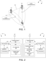
- FIG. 1 illustrates an exemplary wireless network supporting TCI for multiple TRPs in accordance with embodiments of the current invention.
- the wireless network 100 includes a user equipment (UE) 110 communicatively connected to a plurality TRPs 121.
- UE user equipment
- Each TRP 121 may provide radio access using a Radio Access Technology (RAT) (e.g., the 5G NR technology).
- RAT Radio Access Technology
- the UE 110 may be a smart phone, a wearable device, an Internet of Things (IoT) device, and a tablet, etc.
- UE 110 may be a notebook (NB) or Personal Computer (PC) inserted or installed with a data card which includes a modem and RF transceiver(s) to provide the functionality of wireless communication.
- Each TRP 121 may provide communication coverage for a geographic coverage area in which communications with the UE 110 is supported via a communication link 101.
- the communication links 101 shown in the wireless network 100 may respectively include uplink (UL) transmissions from the UE 110 to the TRPs 121 (e.g., on the Physical Uplink Control Channel (PUCCH) or Physical Uplink Shared Channel (PUSCH)) or downlink (DL) transmissions from the TRPs 121 to the UE 110 (e.g., on the Physical Downlink Control Channel (PDCCH) or Physical Downlink Shared Channel (PDSCH)).
- the TRPs 121 may communicate with each other via a communication link 122.
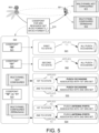
- FIG. 2 is a simplified block diagram of one TRP 121 and the UE 110 in accordance with embodiments of the present invention.
- an antenna 197 transmits and receives radio signal.
- a radio frequency (RF) transceiver 196 coupled with the antenna, receives RF signals from the antenna, converts them to baseband signals and sends them to processor 193.
- RF transceiver 196 also converts received baseband signals from the processor 193, converts them to RF signals, and sends out to antenna 197.
- Processor 193 processes the received baseband signals and invokes different functional modules and circuits to perform features in the TRP 121.
- Memory 192 stores program instructions and data 190 to control the operations of the TRP 121.
- antenna 177 transmits and receives RF signals.
- RF transceiver 176 coupled with the antenna, receives RF signals from the antenna, converts them to baseband signals and sends them to processor 173.
- the RF transceiver 176 also converts received baseband signals from the processor 173, converts them to RF signals, and sends out to antenna 177.
- Processor 173 processes the received baseband signals and invokes different functional modules and circuits to perform features in the UE 110.
- Memory 172 stores program instructions and data 170 to control the operations of the UE 110.
- the TRP 121 and the UE 110 also include several functional modules and circuits that can be implemented and configured to perform embodiments of the present invention.
- the TRP 121 includes a set of control functional modules and circuit 180.
- TCI handling circuit 182 handles TCI and associated network parameters for the UE 110.
- Configuration and control circuit 181 provides different parameters to configure and control the UE 110.
- the UE 110 includes a set of control functional modules and circuit 160.
- Configuration module 161 receives a configuration including at least a first sounding reference signal (SRS) resource set and a second SRS resource set from a wireless network.
- the UE is configured with multiple serving beams with at least a first serving transmission and reception point (TRP) and a second serving TRP.
- SRS sounding reference signal
- TRP transmission and reception point
- Transmission configuration indication module 162 receives a TCI command from the wireless network indicating a first TCI state and a second TCI state.
- Mapping module 163 receives a downlink control information (DCI) format 0_1 or DCI format 0_2 from wireless network and maps the first TCI state, the second TCI state, or both the first TCI state and the second TCI state with at least one physical uplink shared channel (PUSCH) transmission occasion or at least one PUSCH antenna port based on a codepoint for an SRS resource set indicator indicated by the DCI format 0_1 or 0_2.
- DCI downlink control information
- PUSCH physical uplink shared channel
- the different functional modules and circuits can be implemented and configured by software, firmware, hardware, and any combination thereof.
- the function modules and circuits when executed by the processors 193 and 173 (e.g., via executing program codes 190 and 170), allow the TRPs 121 and the UE 110 to perform embodiments of the present invention.
- FIG. 3 illustrates a top-level of message transmissions for multiple TCI states for a UE with multiple serving TRPs in accordance with embodiments of the current invention.
- the TRP 121a transmits a radio resource control (RRC) configuration 1210 of a control resource set (CORESET) or a PUCCH resource to the UE 110.
- the UE 110 receives the RRC configuration 1210 from the TRP 121a.
- the RRC configuration 1210 indicates to the UE 110 multiple transmission configuration indication (TCI) states.
- TCI transmission configuration indication
- the TRP 121a transmits an activation command 1212 (e.g., a MAC-CE) to the UE 110.
- the UE 110 receives the activation command 1212 from the TRP 121a.
- the activation command 1212 is used for the UE 110 to activate subsets of the multiple TCI states.
- the TRP 121a transmits a downlink control information (DCI) 1214 to the UE 110.
- the UE 110 receives the DCI 1214 from the TRP 121a.
- the DCI 1214 indicates to the UE 110 to determine at least one TCI state from the subset(s) of the multiple TCI states as serving TCI(s).
- the RRC configuration 1210 indicates to the UE 110 multiple TCI states which is a general TCI state list associated with both DL reception and UL transmission.
- the activation command 1212 indicates to the UE 110 two subsets of the multiple TCI states.
- One of the subsets is a first list of active TCI states, which includes a plurality of first TCI states.
- the other of the subsets is a second list of active TCI states, which includes a plurality of second TCI states.
- Each of the first TCI states and the second states may be applied for DL reception and UL transmission.
- the UE 110 determines the first TCI states and the second TCI states from the general TCI state list according to the activation command 1212.
- the UE 110 determines the first TCI states and the second TCI states from the general TCI state list by: (1) mapping the first TCI states to a plurality of first TCI field codepoints; and (2) mapping the second TCI states to a plurality of second TCI field codepoints.
- the first TCI field codepoints and the first TCI states may be one-to-one mapped.
- the second TCI field codepoints and the second TCI states may be one-to-one mapped.
- FIG. 4 illustrates exemplary diagrams for top-level procedures for the UE to map the PUSCH transmission with TCI states based on DCI messages in accordance with embodiments of the current invention.
- PUSCH transmission is mapped with TCI state based on DCI messages for the UE communicating with multiple TRPs.
- UE 401 communicates with multiple TRPs, such as TRP 405 and TRP 406.
- UE 401 is equipped and/or configured with multiple panels.
- UE 401 supports multi-beam communication with TRPs 405 and 406.
- UE 401 is configured with multiple serving beams from TRP 405 and TRP 406, respectively.
- the multiple beams of TRP 405 and TRP 406 are in a single cell. Alternatively preferably, the multiple beams of TRP 405 and 406 are from different cells.
- UE 401 is configured with at least two SRS resource sets.
- UE 401 is configured with the first SRS resource set.
- UE 401 is configured with the second SRS resource set.
- the first SRS resource set and the second SRS resource set are codebook-based or noncodebook-based.
- the first SRS resource set and the second SRS resource set are configured with usage parameter set to be "codebook" or "noncodebook”.
- UE 401 is configured with multiple TCI states for the multi-TRP communication.
- UE 401 receives TCI command to indicate/ activate at least two TCI states.
- the network indicates a first TCI state to UE 401.
- the network indicates a second TCI state to UE 401.
- the TCI command is carried by DCI message, such as DCI format 1_1 or DCI format 1_2.
- the TCI command is carried by MAC control element (CE).
- CE MAC control element
- the UE is indicated with joint TCI state or UL TCI state for the mapping of the PUSCH.
- unifiedTCI-StateType "joint”
- the UE is indicated with joint TCI state.
- DCI format 1_1 or DCI format 1_2 or MAC CE indicates 1 st joint TCI state and 2 nd joint TCI state to UE 401.
- unifiedTCI-StateType "separate”
- the UE is indicated with separate DL/UL TCI mode.
- DCI format 1_1 or DCI format 1_2 or MAC CE indicates 1 st DL TCI state, 1 st UL TCI state, 2 nd DL TCI state, and 2 nd UL TCI state.
- UE maps PUSCH transmission with TCI state based on DCI messages.
- UE 401 receives DCI format 0_1 or DCI format 0_2.
- UE maps the TCI states with PUSCH transmission based on the received DCI format 0_1 or DCI format 0_2.
- the UE communicates with multiple TRPs in TDM mode.
- the UE communicates with multiple TRPs in SDM mode.
- the PUSCH transmission maps PUSCH occasions with TCI states.
- the PUSCH transmission maps PUSCH antenna ports with TCI states.
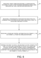
- FIG. 5 illustrates exemplary diagrams for the mapping of PUSCH transmission based on codepoint for SRS resource set in DCI format 0_1 or DCI format 0_2 in accordance with embodiments of the current invention.
- UE 501 communicates with multiple TRPs, such as TRP 502 in a wireless network.
- multi-panel is not configured for UE 501.
- multi-panel is configured for UE 501, such as multi-panel is configured as SDMscheme.
- UE 501 receives DCI format 0_1 or DCI format 0_2 from the network and decodes codepoint for SRS resource set.
- the UE maps PUSCH transmission to TCI states based on the codepoint for SRS resource set in DCI format 0_1 or DCI format 0_2.
- the codepoint for SRS resource set 520 can be set to "00" 521, "01” 522, "10" or "11” 523.
- a DCI format 0_1 or DCI format 0_2 indicates codepoint "00" for the SRS resource set indicator, the UE applies the first indicated joint/UL TCI state to all PUSCH transmission occasions(s).
- a DCI format 0_1 or DCI format 0_2 indicates codepoint "01" for the SRS resource set indicator, the UE applies the second indicated joint/UL TCI state to all PUSCH transmission occasions(s).
- the DCI format 0_1 or DCI format 0_2 indicates codepoint "10" or "11” (523) for SRS resource set indicator, and wherein the PUSCH transmission mapping is further based on a multi-panel scheme of the UE.
- the UE determines a transmission scheme based on the configuration.
- a first transmission schemed is determined when two SRS resource sets are configured with usage for "codebook” or “noncodebook” and multi-panel scheme is not configured.
- a second transmission scheme is determined when two SRS resource sets are configured with usage for "codebook” or “noncodebook” and multi-panel scheme is configured and set to "SDMscheme”.
- the UE applies the first indicated joint/UL TCI state to the PUSCH transmission occasions(s) associated with the first SRS resource set, and the second indicated joint/UL TCI state to the PUSCH transmission occasions(s) associated with the second SRS resource set.
- the UE applies the first indicated joint/UL TCI state to the PUSCH antenna port(s) associated with the first SRS resource set, and the second indicated joint/UL TCI state to the PUSCH antenna port(s) associated with the second SRS resource set.
- the PUSCH antenna port(s) is associated with the first SRS resource set if the PUSCH antenna port(s) corresponds to the SRS port(s) of the indicated SRS resource in the first SRS resource set. In another example, the PUSCH antenna port(s) is associated with the second SRS resource set if the PUSCH antenna port(s) corresponds to the SRS port(s) of the indicated SRS resource in the second SRS resource set.
- Figure 6 illustrates an exemplary flow chart for the UE mapping the PUSCH transmission with TCI state based on DCI messages in accordance with embodiments of the current invention.
- the UE receives a configuration including at least a first sounding reference signal (SRS) resource set and a second SRS resource set from a wireless network.
- the UE is configured with multiple serving beams with at least a first serving transmission and reception point (TRP) and a second serving TRP.
- TRP transmission and reception point
- the UE receives a transmission configuration indication (TCI) command from the wireless network indicating a first TCI state and a second TCI state.
- TCI transmission configuration indication
- the UE receives a downlink control information (DCI) format 0_1 or DCI format 0_2 from wireless network.
- the UE maps the first TCI state, the second TCI state, or both the first TCI state and the second TCI state with at least one physical uplink shared channel (PUSCH) transmission occasion or at least one PUSCH antenna port based on a codepoint for an SRS resource set indicator indicated by the DCI format 0_1 or DCI format 0_2.
- DCI downlink control information
- PUSCH physical uplink shared channel
Landscapes
- Engineering & Computer Science (AREA)
- Signal Processing (AREA)
- Computer Networks & Wireless Communication (AREA)
- Mobile Radio Communication Systems (AREA)
Abstract
Description
- This application claims the benefit under 35 U.S.C. §119 from
U.S. provisional application serial number 63/386,180, entitled "TCI STATE INDICATION FOR PUSCH TRANSMISSION," filed on December 6, 2022 - The disclosed embodiments relate generally to wireless communication, and, more particularly, to transmission configuration indication (TCI) state indication for physical uplink shared channel (PUSCH) transmission.
- In conventional network of 3rd generation partnership project (3GPP) 5G new radio (NR), the user equipment (UE) can be configured, by the network, with control resource sets (CORESETs), search space sets and transmission configuration indication (TCI) states. The UE can apply one or more TCI states for downlink reception and uplink transmission with a transmission reception point (TRP). In some scenarios, the UE may need to communicate with multiple TRPs. However, some details of applying the TCI states for multiple TRPs have not been determined and need to be further discussed.
- Method and user equipment (UE) are provided for the TCI state indication for PUSCH transmission. A method and a user equipment according to the invention are defined in the independent claims. The dependent claims define preferred embodiments thereof. In one novel aspect, the UE maps PUSCH transmission with TCI states based on codepoint for SRS resource set of DCI format 0_1 or DCI format 0_2. Preferably, the PUSCH transmission is for PUSCH transmission occasions. Alternatively or additionally preferably, the PUSCH transmission is for PUSCH antenna ports. Preferably, the UE configures a first SRS resource set and a second SRS resource set, receives a TCI command indicating a first TCI state and a second TCI state, receives a DCI format 0_1 or DCI format 0_2, and maps the first TCI state, the second TCI state, or both the first TCI state and the second TCI state with at least one PUSCH transmission occasions or at least one PUSCH antenna port based on the codepoint for SRS resource set indicator indicated by the DCI format 0_1 or DCI format 0_2. Preferably, the first SRS resource set and the second SRS resource set are configured with usage for codebook or noncodebook. Preferably, UE applies the first TCI state to all PUSCH transmission occasions when the DCI format 0_1 or DCI format 0_2 indicates codepoint "00" for the SRS resource set indicator. The UE applies the second TCI state to all PUSCH transmission occasions when the DCI format 0_1 or DCI format 0_2 indicates codepoint "01" for the SRS resource set indicator. Alternatively or additionally preferably, when the DCI format 0_1 or DCI format 0_2 indicates codepoint "10" or "11" for the SRS resource set indicator, the mapping is further based on a multi-panel scheme of the UE. The UE applies the first TCI state to one or more PUSCH transmission occasions associated with the first SRS resource set and the second TCI state to one or more PUSCH transmission occasions associated with the second SRS resource set when the multi-panel scheme is not configured to the UE by the wireless network. The UE applies the first TCI state to one or more PUSCH antenna ports associated with the first SRS resource set and the second TCI state to one or more PUSCH antenna ports associated with the second SRS resource set when the multi-panel scheme is configured to the UE by the wireless network. Preferably, the multi-panel is configured with SDMscheme. Preferably, the first TCI state and the second TCI state are joint TCI state or UL TCI state. Alternatively or additionally preferably, the TCI command is carried by a DCI format 1_1 or DCI format 1_2 or MAC CE.
- Other embodiments and advantages are described in the detailed description below. This summary does not purport to define the invention. The invention is defined by the claims.
- The accompanying drawings, where like numerals indicate like components, illustrate embodiments of the invention.
-
Figure 1 illustrates an exemplary wireless network supporting TCI for multiple TRPs in accordance with embodiments of the current invention. -
Figure 2 is a simplified block diagram of the TRP and the UE in accordance with embodiments of the current invention. -
Figure 3 illustrates a top-level of message transmissions for multiple TCI states for a UE with multiple serving TRPs in accordance with embodiments of the current invention. -
Figure 4 illustrates exemplary diagrams for top-level procedures for the UE to map the PUSCH transmission with TCI states based on DCI messages in accordance with embodiments of the current invention. -
Figure 5 illustrates exemplary diagrams for the mapping of PUSCH transmission based on codepoint for SRS resource set in DCI format 0_1 or DCI format 0_2 in accordance with embodiments of the current invention. -
Figure 6 illustrates an exemplary flow chart for the UE mapping the PUSCH transmission with TCI state based on DCI messages in accordance with embodiments of the current invention. - Reference will now be made in detail to some embodiments of the invention, examples of which are illustrated in the accompanying drawings.
-
Figure 1 illustrates an exemplary wireless network supporting TCI for multiple TRPs in accordance with embodiments of the current invention. Thewireless network 100 includes a user equipment (UE) 110 communicatively connected to aplurality TRPs 121. - Each TRP 121 may provide radio access using a Radio Access Technology (RAT) (e.g., the 5G NR technology). The UE 110 may be a smart phone, a wearable device, an Internet of Things (IoT) device, and a tablet, etc. Alternatively, UE 110 may be a Notebook (NB) or Personal Computer (PC) inserted or installed with a data card which includes a modem and RF transceiver(s) to provide the functionality of wireless communication.
- Each TRP 121 may provide communication coverage for a geographic coverage area in which communications with the UE 110 is supported via a
communication link 101. Thecommunication links 101 shown in thewireless network 100 may respectively include uplink (UL) transmissions from the UE 110 to the TRPs 121 (e.g., on the Physical Uplink Control Channel (PUCCH) or Physical Uplink Shared Channel (PUSCH)) or downlink (DL) transmissions from theTRPs 121 to the UE 110 (e.g., on the Physical Downlink Control Channel (PDCCH) or Physical Downlink Shared Channel (PDSCH)). The TRPs 121 may communicate with each other via acommunication link 122. -
Figure 2 is a simplified block diagram of oneTRP 121 and theUE 110 in accordance with embodiments of the present invention. For theTRP 121, anantenna 197 transmits and receives radio signal. A radio frequency (RF)transceiver 196, coupled with the antenna, receives RF signals from the antenna, converts them to baseband signals and sends them toprocessor 193.RF transceiver 196 also converts received baseband signals from theprocessor 193, converts them to RF signals, and sends out toantenna 197.Processor 193 processes the received baseband signals and invokes different functional modules and circuits to perform features in the TRP 121.Memory 192 stores program instructions anddata 190 to control the operations of the TRP 121. - Similarly, for the UE 110,
antenna 177 transmits and receives RF signals.RF transceiver 176, coupled with the antenna, receives RF signals from the antenna, converts them to baseband signals and sends them toprocessor 173. TheRF transceiver 176 also converts received baseband signals from theprocessor 173, converts them to RF signals, and sends out toantenna 177.Processor 173 processes the received baseband signals and invokes different functional modules and circuits to perform features in the UE 110.Memory 172 stores program instructions anddata 170 to control the operations of the UE 110. Although a specific number oftransceiver 176 andantenna 177 are depicted infigure 2 , it is contemplated that any number oftransceiver 176 andantenna 177 may be included in the UE 110 for communicating withmultiple TRPs 121 simultaneously. - The TRP 121 and the UE 110 also include several functional modules and circuits that can be implemented and configured to perform embodiments of the present invention. In the example of
figure 2 , the TRP 121 includes a set of control functional modules andcircuit 180.TCI handling circuit 182 handles TCI and associated network parameters for theUE 110. Configuration and control circuit 181 provides different parameters to configure and control the UE 110. TheUE 110 includes a set of control functional modules andcircuit 160. Configuration module 161 receives a configuration including at least a first sounding reference signal (SRS) resource set and a second SRS resource set from a wireless network. Preferably, the UE is configured with multiple serving beams with at least a first serving transmission and reception point (TRP) and a second serving TRP. Transmissionconfiguration indication module 162 receives a TCI command from the wireless network indicating a first TCI state and a second TCI state.Mapping module 163 receives a downlink control information (DCI) format 0_1 or DCI format 0_2 from wireless network and maps the first TCI state, the second TCI state, or both the first TCI state and the second TCI state with at least one physical uplink shared channel (PUSCH) transmission occasion or at least one PUSCH antenna port based on a codepoint for an SRS resource set indicator indicated by the DCI format 0_1 or 0_2. - Note that the different functional modules and circuits can be implemented and configured by software, firmware, hardware, and any combination thereof. The function modules and circuits, when executed by the
processors 193 and 173 (e.g., via executingprogram codes 190 and 170), allow theTRPs 121 and theUE 110 to perform embodiments of the present invention. -
Figure 3 illustrates a top-level of message transmissions for multiple TCI states for a UE with multiple serving TRPs in accordance with embodiments of the current invention. In general, theTRP 121a transmits a radio resource control (RRC) configuration 1210 of a control resource set (CORESET) or a PUCCH resource to theUE 110. TheUE 110 receives the RRC configuration 1210 from theTRP 121a. The RRC configuration 1210 indicates to theUE 110 multiple transmission configuration indication (TCI) states. - The
TRP 121a transmits an activation command 1212 (e.g., a MAC-CE) to theUE 110. TheUE 110 receives the activation command 1212 from theTRP 121a. The activation command 1212 is used for theUE 110 to activate subsets of the multiple TCI states. - The
TRP 121a transmits a downlink control information (DCI) 1214 to theUE 110. TheUE 110 receives the DCI 1214 from theTRP 121a. The DCI 1214 indicates to theUE 110 to determine at least one TCI state from the subset(s) of the multiple TCI states as serving TCI(s). - In some embodiments, the RRC configuration 1210 indicates to the
UE 110 multiple TCI states which is a general TCI state list associated with both DL reception and UL transmission. The activation command 1212 indicates to theUE 110 two subsets of the multiple TCI states. One of the subsets is a first list of active TCI states, which includes a plurality of first TCI states. The other of the subsets is a second list of active TCI states, which includes a plurality of second TCI states. Each of the first TCI states and the second states may be applied for DL reception and UL transmission. - In other words, after receiving the activation command 1212, the
UE 110 determines the first TCI states and the second TCI states from the general TCI state list according to the activation command 1212. - More specifically, the
UE 110 determines the first TCI states and the second TCI states from the general TCI state list by: (1) mapping the first TCI states to a plurality of first TCI field codepoints; and (2) mapping the second TCI states to a plurality of second TCI field codepoints. The first TCI field codepoints and the first TCI states may be one-to-one mapped. The second TCI field codepoints and the second TCI states may be one-to-one mapped. -
Figure 4 illustrates exemplary diagrams for top-level procedures for the UE to map the PUSCH transmission with TCI states based on DCI messages in accordance with embodiments of the current invention. In one novel aspect, PUSCH transmission is mapped with TCI state based on DCI messages for the UE communicating with multiple TRPs.UE 401 communicates with multiple TRPs, such asTRP 405 andTRP 406. Preferably,UE 401 is equipped and/or configured with multiple panels.UE 401 supports multi-beam communication withTRPs UE 401 is configured with multiple serving beams fromTRP 405 andTRP 406, respectively. Preferably, the multiple beams ofTRP 405 andTRP 406 are in a single cell. Alternatively preferably, the multiple beams ofTRP - Preferably,
UE 401 is configured with at least two SRS resource sets. Atstep 411,UE 401 is configured with the first SRS resource set. Atstep 412,UE 401 is configured with the second SRS resource set. In one implementation 410, the first SRS resource set and the second SRS resource set are codebook-based or noncodebook-based. The first SRS resource set and the second SRS resource set are configured with usage parameter set to be "codebook" or "noncodebook". -
UE 401 is configured with multiple TCI states for the multi-TRP communication. Preferably,UE 401 receives TCI command to indicate/ activate at least two TCI states. Atstep 421, the network indicates a first TCI state toUE 401. Atstep 422, the network indicates a second TCI state toUE 401. Preferably, the TCI command is carried by DCI message, such as DCI format 1_1 or DCI format 1_2. Alternatively or additionally preferably, the TCI command is carried by MAC control element (CE). In one implementation 420, the UE is indicated with joint TCI state or UL TCI state for the mapping of the PUSCH. When the serving cell is configured with joint DL/UL TCI mode, i.e., unifiedTCI-StateType = "joint", the UE is indicated with joint TCI state. For example, DCI format 1_1 or DCI format 1_2 or MAC CE indicates 1st joint TCI state and 2nd joint TCI state toUE 401. When the serving cell is configured with separate DL/UL TCI mode, i.e., unifiedTCI-StateType = "separate", the UE is indicated with separate DL/UL TCI mode. For example, DCI format 1_1 or DCI format 1_2 or MAC CE indicates 1st DL TCI state, 1st UL TCI state, 2nd DL TCI state, and 2nd UL TCI state. - In one novel aspect, UE maps PUSCH transmission with TCI state based on DCI messages. At
step 430,UE 401 receives DCI format 0_1 or DCI format 0_2. Atstep 440, UE maps the TCI states with PUSCH transmission based on the received DCI format 0_1 or DCI format 0_2. In one scenario, the UE communicates with multiple TRPs in TDM mode. In another scenario, the UE communicates with multiple TRPs in SDM mode. Preferably, the PUSCH transmission maps PUSCH occasions with TCI states. Alternatively or additionally preferably, the PUSCH transmission maps PUSCH antenna ports with TCI states. -
Figure 5 illustrates exemplary diagrams for the mapping of PUSCH transmission based on codepoint for SRS resource set in DCI format 0_1 or DCI format 0_2 in accordance with embodiments of the current invention.UE 501 communicates with multiple TRPs, such asTRP 502 in a wireless network. In one implementation 511, multi-panel is not configured forUE 501. In anotherimplementation 512, multi-panel is configured forUE 501, such as multi-panel is configured as SDMscheme. Atstep 510,UE 501 receives DCI format 0_1 or DCI format 0_2 from the network and decodes codepoint for SRS resource set. In one novel aspect, the UE maps PUSCH transmission to TCI states based on the codepoint for SRS resource set in DCI format 0_1 or DCI format 0_2. The codepoint for SRS resource set 520 can be set to "00" 521, "01" 522, "10" or "11" 523. Inscenario 531, a DCI format 0_1 or DCI format 0_2 indicates codepoint "00" for the SRS resource set indicator, the UE applies the first indicated joint/UL TCI state to all PUSCH transmission occasions(s). Inscenario 532, a DCI format 0_1 or DCI format 0_2 indicates codepoint "01" for the SRS resource set indicator, the UE applies the second indicated joint/UL TCI state to all PUSCH transmission occasions(s). - Preferably, the DCI format 0_1 or DCI format 0_2 indicates codepoint "10" or "11" (523) for SRS resource set indicator, and wherein the PUSCH transmission mapping is further based on a multi-panel scheme of the UE. The UE determines a transmission scheme based on the configuration. A first transmission schemed is determined when two SRS resource sets are configured with usage for "codebook" or "noncodebook" and multi-panel scheme is not configured. A second transmission scheme is determined when two SRS resource sets are configured with usage for "codebook" or "noncodebook" and multi-panel scheme is configured and set to "SDMscheme". In scenario/
configuration 533 for the first transmission scheme, the UE applies the first indicated joint/UL TCI state to the PUSCH transmission occasions(s) associated with the first SRS resource set, and the second indicated joint/UL TCI state to the PUSCH transmission occasions(s) associated with the second SRS resource set. Inconfiguration 534 for the second transmission scheme, the UE applies the first indicated joint/UL TCI state to the PUSCH antenna port(s) associated with the first SRS resource set, and the second indicated joint/UL TCI state to the PUSCH antenna port(s) associated with the second SRS resource set. In one example, the PUSCH antenna port(s) is associated with the first SRS resource set if the PUSCH antenna port(s) corresponds to the SRS port(s) of the indicated SRS resource in the first SRS resource set. In another example, the PUSCH antenna port(s) is associated with the second SRS resource set if the PUSCH antenna port(s) corresponds to the SRS port(s) of the indicated SRS resource in the second SRS resource set. -
Figure 6 illustrates an exemplary flow chart for the UE mapping the PUSCH transmission with TCI state based on DCI messages in accordance with embodiments of the current invention. Atstep 601, the UE receives a configuration including at least a first sounding reference signal (SRS) resource set and a second SRS resource set from a wireless network. Preferably, the UE is configured with multiple serving beams with at least a first serving transmission and reception point (TRP) and a second serving TRP. Atstep 602, the UE receives a transmission configuration indication (TCI) command from the wireless network indicating a first TCI state and a second TCI state. Atstep 603, the UE receives a downlink control information (DCI) format 0_1 or DCI format 0_2 from wireless network. Atstep 604, the UE maps the first TCI state, the second TCI state, or both the first TCI state and the second TCI state with at least one physical uplink shared channel (PUSCH) transmission occasion or at least one PUSCH antenna port based on a codepoint for an SRS resource set indicator indicated by the DCI format 0_1 or DCI format 0_2. - Although the present invention has been described in connection with certain specific embodiments for instructional purposes, the present invention is not limited thereto. Accordingly, various modifications, adaptations, and combinations of various features of the described embodiments can be practiced without departing from the scope of the invention as set forth in the claims.
Claims (11)
- A method for a user equipment, in the following also referred to as UE, comprising:receiving, from a wireless network, a configuration including at least a first sounding reference signal, in the following also referred to as SRS, resource set and a second SRS resource set (610);receiving a transmission configuration indication, in the following also referred to as TCI, command from the wireless network indicating a first TCI state and a second TCI state (602);receiving a downlink control information, in the following also referred to as DCI, format 0_1 or DCI format 0_2 from the wireless network (603); andmapping the first TCI state, the second TCI state, or both the first TCI state and the second TCI state to at least one physical uplink shared channel, in the following also referred to as PUSCH, transmission occasion or at least one PUSCH antenna port based on a codepoint for an SRS resource set indicator indicated by the DCI format 0_1 or DCI format 0_2 (604).
- A user equipment, in the following also referred to as UE, (110) comprising:a transceiver (176) that transmits and receives radio frequency, in the following also referred to as RF, signals in a wireless network;a configuration module (161) that receives a configuration including at least a first sounding reference signal, in the following also referred to as SRS, resource set and a second SRS resource set from the wireless network;a transmission configuration indication, in the following also referred to as TCI, module (162) that receives a TCI command from the wireless network indicating a first TCI state and a second TCI state; anda mapping module (163) that receives a downlink control information, in the following also referred to as DCI, format 0_1 or DCI format 0_2 from the wireless network and maps the first TCI state, the second TCI state, or both the first TCI state and the second TCI state with at least one physical uplink shared channel, in the following also referred to as PUSCH, transmission occasion or at least one PUSCH antenna port based on a codepoint for an SRS resource set indicator indicated by the DCI format 0_1 or DCI format 0_2.
- The method of claim 1 or the UE (110) of claim 2, wherein the first SRS resource set and the second SRS resource set are configured with usage for codebook or noncodebook.
- The method of claim 1 or 3, or the UE (110) of claim 2 or 3, wherein the UE applies the first TCI state to all PUSCH transmission occasions when the DCI format 0_1 or DCI format 0_2 indicates codepoint "00" for the SRS resource set indicator.
- The method of any one of claims 1, 3 and 4, or the UE (110) of any one of claims 2 to 4, wherein the UE applies the second TCI state to all PUSCH transmission occasions when the DCI format 0_1 or DCI format 0_2 indicates codepoint "01" for the SRS resource set indicator.
- The method of any one of claims 1 and 3 to 5, or the UE (110) of any one of claims 2 to 5, wherein the DCI format 0_1 or DCI format 0_2 indicates codepoint "10" or "11" for the SRS resource set indicator, and wherein the mapping is further based on a multi-panel scheme configured to the UE by the wireless network.
- The method or the UE (110) of claim 6, wherein the UE applies the first TCI state to one or more PUSCH transmission occasions associated with the first SRS resource set and the second TCI state to one or more PUSCH transmission occasions associated with the second SRS resource set when the multi-panel scheme is not configured to the UE by the wireless network.
- The method or the UE (110) of claim 6 or 7, wherein the UE applies the first TCI state to one or more PUSCH antenna ports associated with the first SRS resource set and the second TCI state to one or more PUSCH antenna ports associated with the second SRS resource set when the multi-panel scheme is configured to the UE by the wireless network.
- The method or the UE (110) of claim 8, wherein the multi-panel scheme configured to the UE by the wireless network is set to space division multiplexing, in the following also referred to as SDM, scheme.
- The method of any one of claims 1 and 3 to 9, or the UE (110) of any one of claims 2 to 9, wherein the first TCI state and the second TCI are joint or uplink, in the following also referred to as UL, TCI states.
- The method of any one of claims 1 and 3 to 10, or the UE (110) of any one of claims 2 to 10, wherein the TCI command is carried by a DCI or a medium access control-control element, in the following also referred to as MAC-CE, from the wireless network.
Applications Claiming Priority (2)
| Application Number | Priority Date | Filing Date | Title |
|---|---|---|---|
| US202263386180P | 2022-12-06 | 2022-12-06 | |
| US18/525,680 US20240187185A1 (en) | 2022-12-06 | 2023-11-30 | Tci state indication for pusch transmission |
Publications (2)
| Publication Number | Publication Date |
|---|---|
| EP4383638A2 true EP4383638A2 (en) | 2024-06-12 |
| EP4383638A3 EP4383638A3 (en) | 2024-06-26 |
Family
ID=89119374
Family Applications (1)
| Application Number | Title | Priority Date | Filing Date |
|---|---|---|---|
| EP23214330.5A Pending EP4383638A3 (en) | 2022-12-06 | 2023-12-05 | Tci state indication for pusch transmission |
Country Status (3)
| Country | Link |
|---|---|
| US (1) | US20240187185A1 (en) |
| EP (1) | EP4383638A3 (en) |
| TW (1) | TW202425698A (en) |
Citations (1)
| Publication number | Priority date | Publication date | Assignee | Title |
|---|---|---|---|---|
| EP3879738A1 (en) * | 2020-03-11 | 2021-09-15 | Fraunhofer Gesellschaft zur Förderung der angewandten Forschung e.V. | Methods and apparatuses for physical uplink shared channel for multi transmit-receive-point communications in a wireless communications network |
Family Cites Families (4)
| Publication number | Priority date | Publication date | Assignee | Title |
|---|---|---|---|---|
| US12010695B2 (en) * | 2020-05-14 | 2024-06-11 | Ofinno, Llc | Uplink beam indication with activated beams |
| CN116491183A (en) * | 2020-10-23 | 2023-07-25 | 中兴通讯股份有限公司 | Communication in Multiple Transmit/Receive Point Environments |
| WO2023137654A1 (en) * | 2022-01-20 | 2023-07-27 | Lenovo (Beijing) Limited | Single-dci multi-trp based ul transmission in unified tci framework |
| GB2630862A (en) * | 2022-04-29 | 2024-12-11 | Lenovo Beijing Ltd | Dynamic switching between single-TRP and multi-TRP based PUSCH schemes |
-
2023
- 2023-11-30 US US18/525,680 patent/US20240187185A1/en active Pending
- 2023-12-05 EP EP23214330.5A patent/EP4383638A3/en active Pending
- 2023-12-06 TW TW112147426A patent/TW202425698A/en unknown
Patent Citations (1)
| Publication number | Priority date | Publication date | Assignee | Title |
|---|---|---|---|---|
| EP3879738A1 (en) * | 2020-03-11 | 2021-09-15 | Fraunhofer Gesellschaft zur Förderung der angewandten Forschung e.V. | Methods and apparatuses for physical uplink shared channel for multi transmit-receive-point communications in a wireless communications network |
Non-Patent Citations (1)
| Title |
|---|
| PATRICK MERIAS ET AL: "Summary #3 on Rel-18 STxMP", vol. RAN WG1, no. Toulouse, FR; 20221114 - 20221118, 17 November 2022 (2022-11-17), XP052223133, Retrieved from the Internet <URL:https://www.3gpp.org/ftp/TSG_RAN/WG1_RL1/TSGR1_111/Docs/R1-2212581.zip R1-2212581.docx> [retrieved on 20221117] * |
Also Published As
| Publication number | Publication date |
|---|---|
| US20240187185A1 (en) | 2024-06-06 |
| TW202425698A (en) | 2024-06-16 |
| EP4383638A3 (en) | 2024-06-26 |
Similar Documents
| Publication | Publication Date | Title |
|---|---|---|
| US12237569B2 (en) | Facilitating user equipment beamforming control | |
| US11849446B2 (en) | Method for transmitting uplink data and terminal device | |
| US11153053B2 (en) | Method of performing data transmission by terminal device in a wireless communication system | |
| US20250142550A1 (en) | Multi-TRP Beam Indication Using TCI State | |
| WO2022000262A1 (en) | Systems and methods for determining transmission information | |
| US20230262824A1 (en) | Methods and apparatus to speed up direct acell activation | |
| WO2024065746A1 (en) | Indications of precoder and transmission layer for subscriber data management based simulation uplink transmission | |
| EP4147413B1 (en) | User equipment for sounding reference signal triggering and sounding reference signal triggering method | |
| US12483354B2 (en) | LTE CRS rate matching for 5G NR PDSCH resource mapping | |
| CN118157829A (en) | Transmission configuration indication state indication method, user equipment and storage medium | |
| WO2022028568A1 (en) | Downlink reception with multiple tci states | |
| WO2022062936A1 (en) | Method for monitoring tci field of dci format | |
| US20240187185A1 (en) | Tci state indication for pusch transmission | |
| US20250175879A1 (en) | Method and apparatus for forwarding control information in mobile communications | |
| US20220369323A1 (en) | Method and user equipment for scheduling with multiple cells | |
| CN114765519A (en) | Method for configuring TCI state to be applied to reference signal and user equipment thereof | |
| US20240349298A1 (en) | Method and user equipment for transmission configuration indication for multiple transmission reception points | |
| US20250365116A1 (en) | Method and user equipment for performing uplink transmissions to multiple transmission reception points | |
| CN115250533B (en) | Method and user equipment for wireless communication | |
| US20220330272A1 (en) | Method and User Equipment for Scheduling with Multiple Cells | |
| EP4568397A1 (en) | Information indication method and apparatus, medium, and product | |
| CN117796024A (en) | Method and user equipment for transmission configuration indication of multiple transmission reception points | |
| US20220124752A1 (en) | Tci state activation for downlink transmission and uplink transmission | |
| US20250158762A1 (en) | Uplink data transmitting device and method, and uplink data receiving device and method | |
| US20240314774A1 (en) | Method and apparatus for uplink transmission |
Legal Events
| Date | Code | Title | Description |
|---|---|---|---|
| PUAI | Public reference made under article 153(3) epc to a published international application that has entered the european phase |
Free format text: ORIGINAL CODE: 0009012 |
|
| STAA | Information on the status of an ep patent application or granted ep patent |
Free format text: STATUS: THE APPLICATION HAS BEEN PUBLISHED |
|
| PUAL | Search report despatched |
Free format text: ORIGINAL CODE: 0009013 |
|
| AK | Designated contracting states |
Kind code of ref document: A2 Designated state(s): AL AT BE BG CH CY CZ DE DK EE ES FI FR GB GR HR HU IE IS IT LI LT LU LV MC ME MK MT NL NO PL PT RO RS SE SI SK SM TR |
|
| AK | Designated contracting states |
Kind code of ref document: A3 Designated state(s): AL AT BE BG CH CY CZ DE DK EE ES FI FR GB GR HR HU IE IS IT LI LT LU LV MC ME MK MT NL NO PL PT RO RS SE SI SK SM TR |
|
| RIC1 | Information provided on ipc code assigned before grant |
Ipc: H04B 7/06 20060101ALN20240521BHEP Ipc: H04L 5/00 20060101AFI20240521BHEP |
|
| STAA | Information on the status of an ep patent application or granted ep patent |
Free format text: STATUS: REQUEST FOR EXAMINATION WAS MADE |
|
| 17P | Request for examination filed |
Effective date: 20241209 |
|
| STAA | Information on the status of an ep patent application or granted ep patent |
Free format text: STATUS: EXAMINATION IS IN PROGRESS |
|
| 17Q | First examination report despatched |
Effective date: 20251104 |