EP4383623A1 - Method executed by user equipment, and user equipment - Google Patents
Method executed by user equipment, and user equipment Download PDFInfo
- Publication number
- EP4383623A1 EP4383623A1 EP22852057.3A EP22852057A EP4383623A1 EP 4383623 A1 EP4383623 A1 EP 4383623A1 EP 22852057 A EP22852057 A EP 22852057A EP 4383623 A1 EP4383623 A1 EP 4383623A1
- Authority
- EP
- European Patent Office
- Prior art keywords
- resource
- res
- slot
- pscichs
- coordination
- Prior art date
- Legal status (The legal status is an assumption and is not a legal conclusion. Google has not performed a legal analysis and makes no representation as to the accuracy of the status listed.)
- Pending
Links
Images

Classifications
-
- H—ELECTRICITY
- H04—ELECTRIC COMMUNICATION TECHNIQUE
- H04L—TRANSMISSION OF DIGITAL INFORMATION, e.g. TELEGRAPHIC COMMUNICATION
- H04L1/00—Arrangements for detecting or preventing errors in the information received
- H04L1/12—Arrangements for detecting or preventing errors in the information received by using return channel
- H04L1/16—Arrangements for detecting or preventing errors in the information received by using return channel in which the return channel carries supervisory signals, e.g. repetition request signals
- H04L1/18—Automatic repetition systems, e.g. Van Duuren systems
-
- H—ELECTRICITY
- H04—ELECTRIC COMMUNICATION TECHNIQUE
- H04W—WIRELESS COMMUNICATION NETWORKS
- H04W72/00—Local resource management
- H04W72/20—Control channels or signalling for resource management
- H04W72/25—Control channels or signalling for resource management between terminals via a wireless link, e.g. sidelink
-
- H—ELECTRICITY
- H04—ELECTRIC COMMUNICATION TECHNIQUE
- H04W—WIRELESS COMMUNICATION NETWORKS
- H04W28/00—Network traffic management; Network resource management
- H04W28/16—Central resource management; Negotiation of resources or communication parameters, e.g. negotiating bandwidth or QoS [Quality of Service]
- H04W28/26—Resource reservation
-
- H—ELECTRICITY
- H04—ELECTRIC COMMUNICATION TECHNIQUE
- H04W—WIRELESS COMMUNICATION NETWORKS
- H04W4/00—Services specially adapted for wireless communication networks; Facilities therefor
- H04W4/30—Services specially adapted for particular environments, situations or purposes
- H04W4/40—Services specially adapted for particular environments, situations or purposes for vehicles, e.g. vehicle-to-pedestrians [V2P]
-
- H—ELECTRICITY
- H04—ELECTRIC COMMUNICATION TECHNIQUE
- H04W—WIRELESS COMMUNICATION NETWORKS
- H04W72/00—Local resource management
- H04W72/04—Wireless resource allocation
-
- H—ELECTRICITY
- H04—ELECTRIC COMMUNICATION TECHNIQUE
- H04W—WIRELESS COMMUNICATION NETWORKS
- H04W72/00—Local resource management
- H04W72/04—Wireless resource allocation
- H04W72/044—Wireless resource allocation based on the type of the allocated resource
- H04W72/0446—Resources in time domain, e.g. slots or frames
-
- H—ELECTRICITY
- H04—ELECTRIC COMMUNICATION TECHNIQUE
- H04W—WIRELESS COMMUNICATION NETWORKS
- H04W92/00—Interfaces specially adapted for wireless communication networks
- H04W92/16—Interfaces between hierarchically similar devices
- H04W92/18—Interfaces between hierarchically similar devices between terminal devices
Definitions
- user equipment comprising: a processor; and a memory having instructions stored therein, wherein the instructions, when run by the processor, perform the aforementioned method.
- SL communication can support inter-UE coordination functions, e.g., coordination of resource allocation and/or reservation and/or indication between two or more UEs, so as to improve the efficiency of resource allocation and/or reservation and/or indication and/or reduce conflicts in resource allocation and/or reservation and/or indication, etc.
- inter-UE coordination functions e.g., coordination of resource allocation and/or reservation and/or indication between two or more UEs, so as to improve the efficiency of resource allocation and/or reservation and/or indication and/or reduce conflicts in resource allocation and/or reservation and/or indication, etc.
- the coordination information may be included in 2 nd -stage SCI.
- the coordination information may be included in Sidelink Feedback Control Information (SFCI).
- SFCI Sidelink Feedback Control Information
- SCCI Sidelink Coordination Control Information
- the coordination information may be included in a higher layer (e.g., the MAC layer, or the RRC layer) message.
- the coordination information may be included in a MAC Control Element (MAC CE).
- the coordination information may be included in an RRC message.
- PSCICHS resources may be configured in a resource pool (e.g., configured in an information element SL-ResourcePool ). There may be zero or one "PSCICHS configuration" in one resource pool.
- a PSCICHS resource may occupy one or more sub-channels (or one or more resource blocks) configured in the resource pool, or does not occupy any sub-channel (or any resource block) configured in the resource pool.
- N time , num CI , RES may be present in one PSCICHS slot.
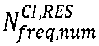
- One PSCICHS resource may occupy N freq , size CI , RES consecutive subcarriers, or N freq , size CI , RES consecutive resource blocks, or N freq , size CI , RES consecutive resource block groups, or N freq , size CI , RES consecutive sub-channels.
- one PSCICHS configuration may include N code , num CI , RES PSCICHS resources (e.g., N code , num CI , RES PSCICHS resources may be multiplexed on a time and frequency resource with the time domain size being N time , size CI , RES and the frequency domain size being N freq , size CI , RES ).
- N code , num CI , RES may be a predefined or configured or pre-configured value, or may be determined by one or more predefined or configured or pre-configured values (e.g., the number of cyclic shifts or the number of cyclic shift pairs).
- One PSCICHS transmission may be associated with one priority.
- the priority may be represented by a priority value.
- the coordination request may be included in a higher layer (e.g., the MAC layer, or the RRC layer) message.
- the coordination request may be included in a MAC CE.
- the coordination request may be included in an RRC message.
- the PSCRCHS resource may be configured in an SL BWP (e.g., configured in an information element SL-BWP-Config or configured in an information element SL-BWP-Generic). There may be zero or one or more "PSCRCHS configurations" in one SL BWP. For each PSCRCHS configuration, the PSCRCHS resource may occupy one or more sub-channels (or one or more resource blocks) configured in one or more resource pools in the SL BWP, or does not occupy any sub-channel (or any resource block) configured in any resource pool in the SL BWP.
- the PSCRCHS resource may be configured in a resource pool (e.g., configured in an information element SL-ResourcePool ) . There may be zero or one PSCRCHS configuration in one resource pool.
- the PSCRCHS resource may occupy one or more sub-channels (or one or more resource blocks) configured in the resource pool, or does not occupy any sub-channel (or any resource block) configured in the resource pool.
- the inter-UE coordination function may be activated (or “enabled”, or “configured”) or deactivated (or disabled) by means of a higher layer protocol parameter (e.g., referred to as sl-ueCoordConfig). For example, if the parameter sl-ueCoordConfig is not present (or not configured), it is indicated that the inter-UE coordination function is not activated. As another example, if the parameter sl-ueCoordConfig is present (or configured), it is indicated that the inter-UE coordination function is activated.
- a higher layer protocol parameter e.g., referred to as sl-ueCoordConfig
- FIG. 1 is a flowchart showing a method performed by user equipment according to Embodiment 1 of the present invention.
- one or more resources are reserved (e.g., the resources are sequentially denoted as r 1 SL , ... , r N rsvd SL , RES SL in chronological order, wherein N rsvd SL , RES ⁇ 1 ).
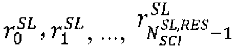
- N SCI SL , RES resources are indicated by a "time resource assignment" field and/or a "frequency resource assignment” field and/or a "resource reservation period” field in SCI (e.g., denoted as SCI 0 ) carried by a PSCCH (e.g., denoted as PSCCH 0 ) and/or a PSSCH (e.g., denoted as PSSCH 0 ) transmitted in a slot t ′ y r 0 SL , u of a resource pool u , and are for example, sequentially denoted as r 0 SL , r 1 SL , ... , r N SCI SL , RES ⁇ 1 SL in chronological order.
- SCI e.g., denoted as SCI 0
- PSCCH e.g., denoted as PSCCH 0
- PSSCH e.g., denoted as PSSCH 0
- SCI 0 includes a coordination request indication (or a coordination enable indication).
- a coordination request indication or a coordination enable indication
- the value of a "coordination enable/disable” field in SCI 0 is set to “enabled”.
- the value of a "coordination request type" field in SCI 0 is set to "resource conflict”.
- a coordination information indication related to some or all of the reserved resources is received.
- a coordination information indication (e.g., denoted as CI i ) is received on a PSCICHS resource c i SL corresponding to (or associated with) the resource r i SL .
- the coordination information indication CI i is received on the PSCICHS resource c i SL .
- the coordination information indication CI i is not received on the PSCICHS resource c i SL .
- the PSCICHS resource c i SL may also be considered as a PSCICHS resource corresponding to (or associated with) SCI 0 or PSCCH 0 or PSSCH 0 .
- the first coordination information indication reception condition includes any one or more of the following (e.g., in any combination of "and” or “or”):
- the coordination information indication CI i may correspond to a predefined or configured or pre-configured coordination type (or referred to as a "coordination mode" or a “coordination scheme”).
- the coordination type may be "resource conflict”.
- the coordination information indication CI i may indicate one or more resource indicator values.
- a set of values that can be indicated by the coordination information indication CI i may be ⁇ resource conflict indicator value 1 ⁇ , or ⁇ resource conflict indicator value 1, resource conflict indicator value 2 ⁇ , where the resource conflict indicator value 1 is not equal to the resource conflict indicator value 2.
- the resource conflict indicator value 1 or the resource conflict indicator value 2 may be any one of the following:
- the coordination type corresponding to the coordination information indication CI i 1 may be the same as or different from the coordination type corresponding to the coordination information indication CI i 2 .
- the PSCICHS resource c i 1 SL and the PSCICHS resource c i 2 SL may be the same PSCICHS resource or two different PSCICHS resources.
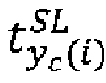
- the slot t y c i SL where the PSCICHS resource c i SL is located may be determined by a parameter in a first coordination parameter set.
- the first coordination parameter set may include any one or more of the following:
- the slot t y c i SL is determined by the slot t ′ y r i SL , u and/or the slot t ′ y r 0 SL , u and/or K RES CI and/or other parameters.
- the slot t y c i SL may be defined according to one of the following manners:
- the first coordination resource slot condition includes any one or more of the following (e.g., in any combination of "and” or “or”):
- an index of the PSCICHS resource c i SL (e.g., an index of the PSCICHS resource c i SL in PSCICHS resources in the slot t y c i SL , and e.g., denoted as x i SL , CI ) is determined by a parameter in a second coordination parameter set.
- the second coordination parameter set may include any one or more of the following:
- one or more elements in the second coordination parameter set may be used to determine one or more offsets for calculating the index x i SL , CI .
- x i SL , CI S i SL , CI + O i SL , CI mod N tfc , num CI , RES , wherein
- B ′ i SL , CI may be an element in the set ⁇ 26, 27, 28, 29, 30, 31, 32 ⁇
- T ′ proc , CI , 5 SL may be an element in the set ⁇ 0 , T proc , CI , 5 SL , T proc , CI , 5 SL ⁇ 1 , T proc , CI , 5 SL + 1 ⁇ .
- step S105 received coordination information is reported.
- the second protocol layer entity of the UE reports, to the first protocol layer entity of the UE, coordination information related to some or all of the resources r 1 SL , ... , r N rsvd SL , RES SL .
- a resource conflict indicator value related to the PSCICHS resource c i SL is not reported.
- a default resource conflict indicator value (e.g., the resource conflict indicator value 1, or the resource conflict indicator value 2, or "no resource conflict is present", or "a resource conflict is present", or "no conflict is present", or "a conflict is present") is reported for the PSCICHS resource c i SL .
- a resource conflict indicator value related to the PSCICHS resource c i SL is not reported.
- a default resource conflict indicator value (e.g., the resource conflict indicator value 1, or the resource conflict indicator value 2, or "no resource conflict is present", or "a resource conflict is present", or "no conflict is present", or "a conflict is present") is reported for the PSCICHS resource c i SL .
- a resource conflict indicator value indicated in a coordination information indication CI i carried by the PSCICHS is reported.
- a resource reservation conflict is present (or “a half-duplex conflict is present", or “a resource conflict is present") is indicated in a coordination information indication CI i carried by the PSCICHS, "a resource conflict is present” (or "a conflict is present") is reported.
- a PSCICHS is received on the PSCICHS resource c i SL , and "no resource reservation conflict is present" (or “no half-duplex conflict is present", or “no resource conflict is present") is indicated in a coordination information indication CI i carried by the PSCICHS, "no resource conflict is present” (or “no conflict is present”) is reported.
- step S103 and step S105 are not performed.
- any one of ⁇ t ′ y r 0 SL , u , t y c i SL , ⁇ t y t i SL t y c i SL , ⁇ t y c i SL , t ′ y r i SL , u , and ⁇ t ′ y r 0 SL , u , t ′ y r i SL , u may be defined according to a physical slot offset, or an SL slot offset, or a slot offset in the resource pool u , or a slot offset in the PSCICHS slot set T RES CI .
- any one of T proc , CI , 1 SL , T proc , CI , 2 SL , T proc , CI , 3 SL , T proc , CI ,4 SL , and T proc , CI , 5 SL may be equal to any one of the following:
- the first protocol layer entity is a MAC layer (or referred to as MAC sub-layer) protocol entity, or an RLC layer protocol entity, or a PDCP layer protocol entity, or an RRC layer protocol entity, or a PC5-RRC layer protocol entity, or a PC5-S layer protocol entity, or a physical layer (or referred to as PHY layer) protocol entity.
- MAC sub-layer or an RLC layer protocol entity, or a PDCP layer protocol entity, or an RRC layer protocol entity, or a PC5-RRC layer protocol entity, or a PC5-S layer protocol entity, or a physical layer (or referred to as PHY layer) protocol entity.
- the second protocol layer entity is a physical layer protocol entity, or a MAC layer protocol entity, or an RLC layer protocol entity, or a PDCP layer protocol entity, or an RRC layer protocol entity, or a PC5-RRC layer protocol entity, or a PC5-S layer protocol entity.
- step S101, step S 103, and step S 105 are performed by the second protocol layer entity of the UE.
- provided in the present invention is a method, in which one or more resources used to transmit a coordination information indication are determined by utilizing specific parameters (e.g., starting sub-channels, etc.) of two or more conflicting resources, thereby effectively reducing the number of coordination information indications required to be transmitted and the use of corresponding resources, and improving the efficiency of inter-UE coordination.
- specific parameters e.g., starting sub-channels, etc.
- inter-UE coordination and other related terms (e.g., “coordination information indication”, “coordination request indication”, “preferred resource indication”, “non-preferred resource indication”, “resource conflict indication”, “sidelink coordination control information”, “physical sidelink coordination information channel/signal”, “physical sidelink coordination request channel/signal”, etc.) may be defined by functions thereof in a system and/or a corresponding procedure and/or corresponding signaling. When applied to a specific system, the terms may be replaced with other names.
- FIG. 2 is used to illustrate user equipment that can perform the method performed by user equipment described in detail above in the present invention as a variant embodiment.
- FIG. 2 shows a block diagram of user equipment (UE) according to the present invention.
- user equipment (UE) 20 includes a processor 201 and a memory 202.
- the processor 201 may include, for example, a microprocessor, a microcontroller, an embedded processor, and the like.
- the memory 202 may include, for example, a volatile memory (such as a random access memory (RAM)), a hard disk drive (HDD), a non-volatile memory (such as a flash memory), or other memories.
- the memory 202 stores program instructions. The instructions, when run by the processor 201, can implement the above method performed by user equipment as described in detail in the present invention.
- the method and related equipment according to the present invention have been described above in combination with preferred embodiments. It should be understood by those skilled in the art that the method shown above is only exemplary, and the above embodiments can be combined with one another as long as no contradiction arises.
- the method of the present invention is not limited to the steps or sequences illustrated above.
- the network node and user equipment shown above may include more modules, for example, modules that may be developed or developed in the future and may be used for a base station, an Access and Mobility Management Function (AMF), a User Plane Function (UPF), a Mobility Management Entity (MME), a Serving Gateway (S-GW), or UE.
- AMF Access and Mobility Management Function
- UPF User Plane Function
- MME Mobility Management Entity
- S-GW Serving Gateway
- UE User Plane Function
- Various identifiers shown above are only exemplary, and are not meant for limiting the present invention.
- a subset of a set may be the set itself.
- various components of the base station and user equipment in the above embodiments can be implemented by multiple devices, and these devices include, but are not limited to, an analog circuit device, a digital circuit device, a digital signal processing (DSP) circuit, a programmable processor, an application-specific integrated circuit (ASIC), a field-programmable gate array (FPGA), a complex programmable logic device (CPLD), and the like.
- DSP digital signal processing
- ASIC application-specific integrated circuit
- FPGA field-programmable gate array
- CPLD complex programmable logic device
- the term “base station” may refer to a mobile communication data and/or control switching center having specific transmission power and a specific coverage area and including functions such as resource allocation and scheduling, data reception and transmission, and the like.
- the term “user equipment” may refer to a user mobile terminal, such as a terminal device that can perform wireless communication with a base station or a micro base station, including a mobile phone, a laptop computer, and the like.
- the embodiments of the present invention disclosed herein may be implemented on a computer program product.
- the computer program product is a product provided with a computer-readable medium having computer program logic encoded thereon.
- the computer program logic When executed on a computing device, the computer program logic provides related operations to implement the above technical solutions of the present invention.
- the computer program logic When executed on at least one processor of a computing system, the computer program logic causes the processor to perform the operations (the method) described in the embodiments of the present invention.
- Such setting of the present invention is typically provided as software, codes and/or other data structures provided or encoded on the computer-readable medium, e.g., an optical medium (e.g., compact disc read-only memory (CD-ROM)), a flexible disk or a hard disk and the like, or other media such as firmware or micro codes on one or more read-only memory (ROM) or random access memory (RAM) or programmable read-only memory (PROM) chips, or a downloadable software image, a shared database and the like in one or more modules.
- Software or firmware or such configuration may be installed on a computing device such that one or more processors in the computing device perform the technical solutions described in the embodiments of the present invention.
- each functional module or each feature of the base station device and the terminal device used in each of the above embodiments may be implemented or executed by a circuit, which is usually one or more integrated circuits.
- Circuits designed to execute various functions described in this description may include general-purpose processors, digital signal processors (DSPs), application-specific integrated circuits (ASICs) or general-purpose integrated circuits, field-programmable gate arrays (FPGAs) or other programmable logic devices, discrete gates or transistor logic, or discrete hardware components, or any combination of the above.
- the general purpose processor may be a microprocessor, or the processor may be an existing processor, a controller, a microcontroller, or a state machine.
- the aforementioned general purpose processor or each circuit may be configured by a digital circuit or may be configured by a logic circuit. Furthermore, when advanced technology capable of replacing current integrated circuits emerges due to advances in semiconductor technology, the present invention can also use integrated circuits obtained using this advanced technology.
Landscapes
- Engineering & Computer Science (AREA)
- Computer Networks & Wireless Communication (AREA)
- Signal Processing (AREA)
- Quality & Reliability (AREA)
- Mobile Radio Communication Systems (AREA)
Abstract
Description
- The present invention relates to a method performed by user equipment, and user equipment.
- Sidelink (SL) communication (e.g., when SL resource allocation mode 2 is configured) can support inter-user equipment (UE) coordination functions, e.g., coordination of resource allocation between two or more UEs. The inter-UE coordination functions need to solve a series of problems, for example, how to determine two or more UEs related to inter-UE coordination, and how to determine one or more messages related to inter-UE coordination and definitions, configurations, mapping, transmission, reception, etc., of resources respectively used thereby.
-
- Non-Patent Document 1: RP-152293, New WI proposal: Support for V2V services based on LTE sidelink
- Non-Patent Document 2: RP-170798, New WID on 3GPP V2X Phase 2
- Non-Patent Document 3: RP-170855, New WID on New Radio Access Technology
- Non-Patent Document 4: RP-190766, New WID on 5G V2X with NR sidelink
- Non-Patent Document 5: RP-201385, WID revision: NR sidelink enhancement
- In order to solve at least a portion of the above problems, provided in the present invention are a method performed by user equipment, and user equipment. One or more resources used to transmit a coordination information indication are determined by utilizing specific parameters (e.g., starting sub-channels, etc.) of two or more conflicting resources, thereby effectively reducing the number of coordination information indications required to be transmitted and the use of corresponding resources, and improving the efficiency of inter-UE coordination.
- According to the present invention, provided is a method performed by user equipment, comprising: reserving a resource


- In addition, according to the present invention, provided is user equipment, comprising: a processor; and a memory having instructions stored therein, wherein the instructions, when run by the processor, perform the aforementioned method.
- Therefore, provided in the present invention is a method, in which one or more resources used to transmit a coordination information indication are determined by utilizing specific parameters (e.g., starting sub-channels, etc.) of two or more conflicting resources, thereby effectively reducing the number of coordination information indications required to be transmitted and the use of corresponding resources, and improving the efficiency of inter-UE coordination.
- The above and other features of the present invention will be more apparent from the following detailed description in combination with the accompanying drawings, in which:
-
FIG. 1 is a flowchart showing a method performed by user equipment according to Embodiment 1 of the present invention. -
FIG. 2 shows a block diagram of user equipment (UE) according to the present invention. - The following describes the present invention in detail with reference to the accompanying drawings and specific embodiments. It should be noted that the present invention should not be limited to the specific embodiments described below. In addition, detailed descriptions of well-known technologies not directly related to the present invention are omitted for the sake of brevity, in order to avoid obscuring the understanding of the present invention.
- In the following description, a 5G (or referred to as "New Radio" (NR) or 5G NR) mobile communication system and later evolved versions (e.g., 5G Advanced) thereof are used as exemplary application environments to specifically describe a plurality of embodiments according to the present invention. However, it is to be noted that the present invention is not limited to the following embodiments, but is applicable to many other wireless communication systems, such as a communication system after 5G and a 4G mobile communication system before 5G.
- The terms given in the present invention may vary in Long Term Evolution (LTE), LTE-Advanced, LTE-Advanced Pro, NR, and subsequent communication systems, but unified terms are used in the present invention. When applied to a specific system, the terms may be replaced with terms used in the corresponding system.
- Unless otherwise specified, in all embodiments and implementations of the present invention:
- Optionally, the eNB may refer to a 4G base station. For example, the eNB may provide termination of Evolved UMTS Terrestrial Radio Access (E-UTRA) user plane and control plane protocols to the UE. As another example, the eNB may be connected to an Evolved Packet Core (EPC) via an S 1 interface.
- Optionally, the ng-eNB may refer to an enhanced 4G base station. For example, the ng-eNB may provide termination of E-UTRA user plane and control plane protocols to the UE. As another example, the ng-eNB may be connected to a 5G core network (5GC) via an NG interface.
- Optionally, the gNB may refer to a 5G base station. For example, the gNB may provide termination of NR user plane and control plane protocols to the UE. As another example, the gNB may be connected to a 5GC via an NG interface.
- Optionally, "send" and "transmit" are interchangeable.
- Optionally, a "symbol" may refer to an Orthogonal Frequency Division Multiplexing (OFDM) symbol.
- Optionally, any two of "within X", "in X", and "on X" are interchangeable with each other. X may be one or more carriers (e.g., an SL carrier), or one or more Bandwidth Parts (BWPs) (e.g., an SL BWP), or one or more resource pools (e.g., SL resource pools), or one or more links (e.g., an uplink (UL), a downlink (DL), or an SL), or one or more channels (e.g., a Physical Sidelink Shared Channel (PSSCH)), or one or more sub-channels, or one or more Resource Block Groups (RBGs), or one or more Resource Blocks (RBs), or one or more "occasions" (e.g., a Physical Downlink Control Channel (PDCCH) monitoring occasion, a PSSCH transmission occasion, a PSSCH reception occasion, a physical sidelink feedback channel (PSFCH) transmission occasion, a PSFCH reception occasion, or the like), or one or more OFDM symbols, or one or more slots, or one or more subframes, or one or more half-frames, or one or more frames, or one or more time-domain and/or frequency-domain and/or code-domain and/or spatial-domain resources, etc.
- Optionally, "higher layer" may refer to one or more protocol layers or protocol sublayers above a physical layer, such as a Medium Access Control (MAC) layer, a Radio Link Control (RLC) layer, a Packet Data Convergence Protocol (PDCP) layer, a PC5 Radio Resource Control (RRC) layer, a PC5-S, an RRC layer, a Vehicle-to-everything (V2X) layer, an application layer, a V2X application layer, or the like.
- Optionally, "pre-configure" may be pre-configuration performed in a higher-layer protocol, such as pre-configured in a specific storage location in the UE (for example, pre-configured according to the specification of the higher layer protocol), or pre-configured in a specific storage location that can be accessed by the UE (for example, pre-configured according to the specification of the higher layer protocol).
- Optionally, "configure" may be configuration performed in a higher-layer protocol by means of signaling. For example, configuration is performed for the UE by means of RRC signaling.
- ◆ Optionally, one "resource" may correspond to one or more parameters (e.g., a starting symbol of the resource, or a starting slot of the resource, or the number of symbols occupied by the resource, or the number of slots occupied by the resource, or the symbol where the resource is located (when the resource occupies only one symbol), or the slot where the resource is located (when the resource occupies only one slot)) in the time domain, and/or one or more parameters (e.g., a starting sub-channel of the resource, or a starting resource block of the resource, or a starting subcarrier of the resource, or the number of sub-channels occupied by the resource, or the number of resource blocks occupied by the resource, or the number of subcarriers occupied by the resource) in the frequency domain, and/or one or more parameters (e.g., a cyclic shift value corresponding to the resource or a corresponding a cyclic shift index, or a cyclic shift pair value corresponding to the resource or a corresponding a cyclic shift pair index) in the code domain, and/or one or more parameters (e.g., a layer corresponding to the resource, or referred to as a Multiple Input Multiple Output (MIMO) layer) in the spatial domain.
- Optionally, a time-domain resource may also be referred to as a time resource.
- Optionally, a frequency-domain resource may also be referred to as a frequency resource.
- Optionally, a resource block may refer to a Virtual Resource Block (VRB), or a Physical Resource Block (PRB), or a Common Resource Block (CRB), or a resource block defined in another manner.
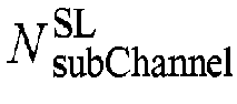
- Optionally, frequency domain resource numbers (e.g., in ascending order of the frequency) may start from 0. For example, if the number of sub-channels (or subchannels) configured in a resource pool is

- Optionally, time domain resource numbers (e.g., in chronological order) may start from 0. For example, for 30 kHz SCS, a set of slots in a subframe may be represented by a set of corresponding slot indexes as {0, 1}.
- Optionally, Sidelink Control Information "SCI" may refer to an instance of an SCI format (e.g., SCI format 1-A), or a combination of an instance of a 1st-stage SCI format (e.g., SCI format 1-A) and an instance of a corresponding 2nd-stage SCI format (e.g., SCI format 2-A), where applicable. For example, in a received SCI format 1-A, each field corresponds to a determined value. As another example, in an SCI format 1-A for transmission (or, to be transmitted), a value has been determined (or is to be determined) for each field. As another example, for a received SCI format 1-A and a corresponding SCI format 2-A, each field of each SCI format corresponds to a determined value.
- Optionally, an "SL transmission" may include any one or more of the following:
- ◆ PSSCH transmission.
- ◆ Physical Sidelink Control Channel (PSCCH) and corresponding (or associated) PSSCH transmission.
- ◆ PSCCH or corresponding (or associated) PSSCH transmission.
- ◆ PSFCH transmission.
- ◆ Sidelink-Synchronization Signal/Physical Sidelink Broadcast Channel (S-SS/PSBCH) transmission (or referred to as S-SSB transmission).
- Optionally, an "SL resource" is a resource that can be used for SL transmission.
- Optionally, "PSSCH transmission" may be replaced with "PSCCH and/or corresponding (or associated) PSSCH transmission".
- Optionally, an "SL slot" is a slot that may belong to a certain resource pool, for example, if a set of indexes of all slots (e.g., referred to as "physical slots") in a predefined period (e.g., a System Frame Number (SFN) period, or a Direct Frame Number (DFN) period; e.g., a duration of 10240 milliseconds; e.g., from SFN = 0 to SFN = 1023, or from DFN = 0 to DFN = 1023) is denoted as Tall = {0,1, ···,10240 × 2 µ
SL - 1} (where µSL is a subcarrier spacing configuration of corresponding SL carriers or SL BWPs), then an "SL slot" set (e.g., denoted as

- ◆ Slots configured with S-SSB.
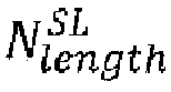
- ◆ Slots where at least one of SL symbols (e.g.,


- ◆ Reserved slots.
- Optionally, an offset between a slot t 1 and a slot t 2 (or referred to as an offset of the slot t 2 relative to the slot t 1, or referred to as an offset from the slot t 1 to the slot t 2) may be denoted as Δ(t 1, t 2). Δ(t 1, t 2) may be defined as one of the following:
- ◆ A physical slot offset. For example, Δ(t 1, t 2) may be a difference between the index of the slot t 2 in the physical slot set Tall and the index of the slot t 1 in the physical slot set Tall. The slot t 1 and the slot t 2 may belong to the same resource pool, or belong to two different resource pools, or do not belong to any resource pool, or one of the slot t 1 and the slot t 2 belongs to a certain resource pool, and the other does not belong to any resource pool.
- ◆ An SL slot offset. For example, Δ(t 1, t 2) may be a difference between the subscript of the slot t 2 in the SL slot set


- ◆ A slot offset in a resource pool. For example, if a slot set of a resource pool u in a predefined period (e.g., an SFN period, or a DFN period; e.g., a duration of 10240 milliseconds; e.g., from SFN = 0 to SFN = 1023, or from DFN = 0 to DFN = 1023 is denoted as



- ◆ A slot offset in a given slot set. For example, if a slot set in a predefined period (e.g., an SFN period, or a DFN period; e.g., a duration of 10240 milliseconds; e.g., from SFN = 0 to SFN = 1023, or from DFN = 0 to DFN = 1023) is denoted as


- SL communication can support inter-UE coordination functions, e.g., coordination of resource allocation and/or reservation and/or indication between two or more UEs, so as to improve the efficiency of resource allocation and/or reservation and/or indication and/or reduce conflicts in resource allocation and/or reservation and/or indication, etc. Specifically, for example, one UE (e.g., referred to as UE-A) may transmit, to each of one or more other UEs (e.g., collectively referred to as UE-B, or respectively referred to as UE-B1, UE-B2, ......), a "coordination information indication", where coordination information included therein may explicitly or implicitly indicate (or correspond to, or be associated with) one or more resource sets (e.g., referred to as "coordination resource sets"). One coordination information indication (or one coordination resource set) may correspond to one coordination type (or referred to as a "coordination mode" or a "coordination scheme"). A resource in a resource set may be a conflicting resource detected by UE-A (correspondingly, the coordination information indication may be referred to as a "resource conflict indication"), or may be a resource that UE-A expects UE-B to use preferentially (correspondingly, the coordination information indication may be referred to as a "preferred resource indication"), or may be a resource that UE-A does not expect UE-B to use (correspondingly, the coordination information indication may be referred to as a "non-preferred resource indication"). The coordination information may be included in control information. The control information may be physical layer control information, or higher layer control information. For example, the coordination information may be included in 1st-stage SCI. As another example, the coordination information may be included in 2nd-stage SCI. As another example, the coordination information may be included in Sidelink Feedback Control Information (SFCI). As another example, the coordination information may be included in other control information (e.g., referred to as Sidelink Coordination Control Information (SCCI)).
- The coordination information may be included in a higher layer (e.g., the MAC layer, or the RRC layer) message. For example, the coordination information may be included in a MAC Control Element (MAC CE). As another example, the coordination information may be included in an RRC message.
- One coordination information indication may be carried by one physical layer channel (or one transmission of the physical layer channel), or may be carried by one physical layer signal (or one transmission of the physical layer signal). For convenience, the physical layer channel/signal may be referred to as a "Physical Sidelink Coordination Information Channel/Signal" (PSCICHS).
- A resource (e.g., a time domain and/or frequency domain and/or code domain and/or spatial domain resource) occupied by a PSCICHS (or a PSCICHS transmission) may be referred to as a "PSCICHS resource". Optionally, a PSCICHS resource may be referred to as a "PSCICHS occasion" or "PSCICHS occasion resource" or "PSCICHS resource occasion". For a UE that transmits a PSCICHS, a PSCICHS resource may be referred to as a "PSCICHS transmission resource" or "PSCICHS transmission occasion" or "PSCICHS transmission occasion resource" or "PSCICHS transmission resource occasion". For a UE that receives a PSCICHS, a PSCICHS resource may be referred to as a "PSCICHS reception resource" or "PSCICHS reception occasion" or "PSCICHS reception occasion resource" or "PSCICHS reception resource occasion".
- PSCICHS resources may be configured in an SL carrier (e.g., configured in an information element SL-FreqConfigCommon or configured in an information element SL-FreqConfig). There may be zero or one or more "PSCICHS configurations" in one SL carrier.
- PSCICHS resources may be configured in an SL BWP (e.g., configured in an information element SL-BWP-Config or configured in an information element SL-BWP-Generic). There may be zero or one or more "PSCICHS configurations" in one SL BWP. For each PSCICHS configuration, a PSCICHS resource may occupy one or more sub-channels (or one or more resource blocks) configured in one or more resource pools in the SL BWP, or does not occupy any sub-channel (or any resource block) configured in any resource pool in the SL BWP.
- PSCICHS resources may be configured in a resource pool (e.g., configured in an information element SL-ResourcePool). There may be zero or one "PSCICHS configuration" in one resource pool. A PSCICHS resource may occupy one or more sub-channels (or one or more resource blocks) configured in the resource pool, or does not occupy any sub-channel (or any resource block) configured in the resource pool.
- In the time domain, PSCICHS resources may occur periodically. A slot with PSCICHS resources may be referred to as a "PSCICHS resource slot" (or referred to as a "PSCICHS slot"). For a PSCICHS configuration, in a predefined period (e.g., an SFN period, or a DFN period; e.g., a duration of 10240 milliseconds; e.g., from SFN = 0 to SFN = 1023, or from DFN = 0 to DFN = 1023), a PSCICHS slot set may be denoted as





- In the time domain, the size of a PSCICHS resource (e.g., denoted as


- In the time domain, one or more (e.g., denoted as





- In the frequency domain, the size of a PSCICHS resource (e.g., denoted as


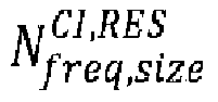


- In the frequency domain, one PSCICHS configuration may include
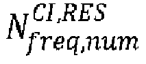



- In the code domain, one PSCICHS resource may correspond to one cyclic shift value or an index of the cyclic shift value. The cyclic shift value may be used to determine a sequence corresponding to a PSCICHS transmission on the PSCICHS resource. For example, the sequence may be acquired by performing a corresponding cyclic shift on a predefined or configured or pre-configured base sequence, and is used to represent a value indicated in coordination information carried in the PSCICHS transmission. Optionally, a "cyclic shift value" may also be referred to as a "cyclic shift".
- In the code domain, one PSCICHS resource may correspond to one cyclic shift pair value or an index of the cyclic shift pair value. The cyclic shift pair value may correspond to two cyclic shift values (e.g., 0 and 6). Each cyclic shift value may be used to determine a sequence corresponding to a PSCICHS transmission on the PSCICHS resource. For example, each sequence may be acquired by performing a corresponding cyclic shift on a predefined or configured or pre-configured base sequence, and is used to represent a value indicated in coordination information carried in the PSCICHS transmission. Optionally, a "cyclic shift pair value" may also be referred to as a "cyclic shift pair".
- In the code domain, one PSCICHS configuration may include


- For one PSCICHS configuration,


- One PSCICHS transmission may be associated with one priority. The priority may be represented by a priority value.
- A coordination information indication may be triggered autonomously by a UE transmitting the coordination information. For example, if UE-A detects that resources respectively indicated (or reserved, or allocated) by UE-B 1 and UE-B2 conflict with each other, UE-A may indicate the conflict via one or more SL transmissions carrying coordination information.
- A coordination information indication may be triggered by a "coordination request indication". For example, UE-B transmits a coordination request indication (e.g., which may include a coordination type indication, e.g., a "resource conflict") to UE-A, and as a response, UE-A may detect whether a resource conflict occurs between UE-B and other UEs (e.g., including UE-A or not including UE-A), and include a detection result in a coordination information indication and transmit the same to UE-B.
- Optionally, a coordination request may be considered as a means of enabling an inter-UE coordination function. In this sense, the coordination request may be referred to as "coordination enable". For example, a UE that does not support the inter-UE coordination function does not transmit a coordination request indication, while a UE that supports the inter-UE coordination function may or may not transmit a coordination request indication. Optionally, in order to avoid transmission of unnecessary coordination information indications, the coordination information indication may be transmitted to only some UEs involved in one resource conflict. For example, if UE-A detects a resource conflict between a resource Ri reserved by SCI1 and a resource R2 reserved by SCI2, and "coordination enable" is indicated in SCI1 while "coordination enable" is not indicated in SCI2 (or, "coordination disable" is indicated in SCI2), then UE-A may transmit a coordination information indication associated with SCI1 (or R1), but does not transmit a coordination information indication associated with SCI2 (or R2).
- The coordination request may be included in control information. The control information may be physical layer control information, or higher layer control information. For example, the coordination request may be included in 1st-stage SCI. As another example, the coordination request may be included in 2nd-stage SCI. As another example, the coordination request may be included in SFCI. As another example, the coordination request may be included in other control information (e.g., in SCCI).
- The coordination request may be included in a higher layer (e.g., the MAC layer, or the RRC layer) message. For example, the coordination request may be included in a MAC CE. As another example, the coordination request may be included in an RRC message.
- A coordination request indication may be carried by one physical layer channel (or one transmission of the physical layer channel), or may be carried by one physical layer signal (or one transmission of the physical layer signal). For convenience, the physical layer channel/signal may be referred to as a "Physical Sidelink Coordination Request Channel/Signal" (PSCRCHS). Optionally, depending on different coordination types, the PSCRCHSs may be different physical layer channels or signals. For example, for a preferred resource indication and/or a non-preferred resource indication, the PSCRCHS may be a PSCCH, or a PSSCH, or a PSCCH+PSSCH, or another physical layer channel, or a physical layer signal. For a resource conflict indication, the PSCRCHS may be a PSFCH, or another physical layer channel, or a physical layer signal.
- A resource (such as a time-domain and/or frequency-domain and/or code-domain and/or spatial-domain resource) occupied by a PSCRCHS (or a PSCRCHS transmission) may be referred to as a "PSCRCHS resource". Optionally, a PSCRCHS resource may be referred to as a "PSCRCHS occasion" or "PSCRCHS occasion resource" or "PSCRCHS resource occasion". For a UE that transmits a PSCRCHS, a PSCRCHS resource may be referred to as a "PSCRCHS transmission resource" or "PSCRCHS transmission occasion" or "PSCRCHS transmission occasion resource" or "PSCRCHS transmission resource occasion". For a UE that receives a PSCRCHS, a PSCRCHS resource may be referred to as a "PSCRCHS reception resource" or "PSCRCHS reception occasion" or "PSCRCHS reception occasion resource" or "PSCRCHS reception resource occasion".
- The PSCRCHS resource may be configured in an SL carrier (e.g., configured in an information element SL-FreqConfigCommon or configured in an information element SL-FreqConfig). There may be zero or one or more "PSCRCHS configurations" in one SL carrier.
- The PSCRCHS resource may be configured in an SL BWP (e.g., configured in an information element SL-BWP-Config or configured in an information element SL-BWP-Generic). There may be zero or one or more "PSCRCHS configurations" in one SL BWP. For each PSCRCHS configuration, the PSCRCHS resource may occupy one or more sub-channels (or one or more resource blocks) configured in one or more resource pools in the SL BWP, or does not occupy any sub-channel (or any resource block) configured in any resource pool in the SL BWP.
- The PSCRCHS resource may be configured in a resource pool (e.g., configured in an information element SL-ResourcePool). There may be zero or one PSCRCHS configuration in one resource pool. The PSCRCHS resource may occupy one or more sub-channels (or one or more resource blocks) configured in the resource pool, or does not occupy any sub-channel (or any resource block) configured in the resource pool.
- The inter-UE coordination function may be activated (or "enabled", or "configured") or deactivated (or disabled) by means of a higher layer protocol parameter (e.g., referred to as sl-ueCoordConfig). For example, if the parameter sl-ueCoordConfig is not present (or not configured), it is indicated that the inter-UE coordination function is not activated. As another example, if the parameter sl-ueCoordConfig is present (or configured), it is indicated that the inter-UE coordination function is activated. As another example, if the value of the parameter sl-ueCoordConfig (or a certain parameter in an information element corresponding to the parameter sl-ueCoordConfig) is a predefined value (e.g., "disabled", "false", or the like), it is indicated that the inter-UE coordination function is not activated. As another example, if the value of the parameter sl-ueCoordConfig (or a certain parameter in an information element corresponding to the parameter sl-ueCoordConfig) is a predefined value (e.g., "enabled", "true", or the like), it is indicated that the inter-UE coordination function is activated.
- A method performed by user equipment according to Embodiment 1 of the present invention will be described below with reference to
FIG. 1 . -
FIG. 1 is a flowchart showing a method performed by user equipment according to Embodiment 1 of the present invention. - As shown in
FIG. 1 , in Embodiment 1 of the present invention, the steps performed by the user equipment (UE) include: step S101, step S103, and optional step S105. - Specifically, in step S101, one or more resources are reserved (e.g., the resources are sequentially denoted as


- For example,


-

- An SL BWP where the resource pool u is located is w. A corresponding subcarrier spacing configuration is µSL. An SL carrier where the SL BWP w is located is a.
- A slot set of the resource pool u is


- The resource


- Slots where the resources


- Starting sub-channels of the resources





- The resources

- Optionally, SCI0 includes a coordination request indication (or a coordination enable indication). For example, the value of a "coordination enable/disable" field in SCI0 is set to "enabled". As another example, the value of a "coordination request type" field in SCI0 is set to "resource conflict".
- In addition, in step S103, a coordination information indication related to some or all of the reserved resources is received. For example, for all


- Optionally, the PSCICHS resource

- Optionally, for the resource

- An inter-UE coordination function has been configured or pre-configured to be "enabled".
- The UE has been configured to be in SL resource allocation mode 2 (or referred to as "resource allocation mode 2"). That is, the UE autonomously determines a resource for SL transmission.
- SCI0 includes a coordination request indication (or a coordination enable indication). For example, the value of a "coordination enable/disable" field in SCI0 is set to "enabled". As another example, the value of a "coordination request type" field in SCI0 is set to "resource conflict".
- The resource pool u (or the SL BWP w, or the SL carrier a) is configured with PSCICHS resources.
- The slot (e.g., denoted as




- A first protocol layer entity of the UE has instructed a second protocol layer entity of the UE to report coordination information related to the resource


- Optionally, the coordination information indication CIi may correspond to a predefined or configured or pre-configured coordination type (or referred to as a "coordination mode" or a "coordination scheme"). The coordination type may be "resource conflict". Correspondingly, the coordination information indication CIi may indicate one or more resource indicator values. For example, a set of values that can be indicated by the coordination information indication CIi may be {resource conflict indicator value 1}, or {resource conflict indicator value 1, resource conflict indicator value 2}, where the resource conflict indicator value 1 is not equal to the resource conflict indicator value 2. The resource conflict indicator value 1 or the resource conflict indicator value 2 may be any one of the following:
- "A resource reservation conflict is present". For example, the resource

- "No resource reservation conflict is present". For example, a situation corresponding to "a resource reservation conflict is present" is not detected.
- "A half-duplex conflict is present". For example, the resource

- "No half-duplex conflict is present". For example, a situation corresponding to "a half-duplex conflict is present" is not detected.
- "A resource conflict is present". For example, a situation corresponding to "a resource reservation conflict is present" or a situation corresponding to "a half-duplex conflict is present" is detected.
- "No resource conflict is present". For example, a situation corresponding to "a resource conflict is present" is not detected.
- Optionally, for


1 may be the same as or different from the coordination type corresponding to the coordination information indication CI i2 . The PSCICHS resource

- Optionally, the slot


- The value of the "time resource assignment" field in SCI 0 .
- The value of the "frequency resource assignment" field in SCI 0 .
- The value of the "resource reservation period" field in SCI 0 .
-

-

-

-

-

-

-

-

- LsubCH.
- The PSCICHS slot period (e.g., denoted as


- The PSCICHS slot offset (e.g., denoted as


- The minimum spacing between a reserved resource and a PSCICHS resource (e.g., denoted as


- For example, the slot


-

-


- Optionally, the first coordination resource slot condition includes any one or more of the following (e.g., in any combination of "and" or "or"):
-


-


-


-


-


-


- Wherein,
- Optionally,





- ◆

- ◆

- ◆

- ◆

- ◆

- ◆

- ◆

- ◆

- ◆

- ◆
- Optionally, an index of the PSCICHS resource



- • The value of the "time resource assignment" field in SCI 0 .
- • The value of the "frequency resource assignment" field in SCI 0 .
- • The value of the "resource reservation period" field in SCI 0 .
- •

- •

- •

- •

- •

- •

- •

- •

- • LsubCH.
- •

- •

- •

- For example, one or more elements in the second coordination parameter set may be used to determine one or more offsets for calculating the index


-


-




- Wherein,
-


-

- ◆ A predefined or configured or pre-configured value (e.g.,

- ◆ The number of sub-channels of the resource pool u (e.g., denoted as

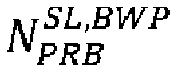
- ◆ The number of resource blocks of the resource pool u (e.g., configured by a parameter sl-RB-Number, and e.g., equal to

- ◆ The number of sub-channels of the SL BWP w (e.g.,


- ◆ The number
- ◆ A predefined or configured or pre-configured value (e.g.,
-

- ◆ A predefined or configured or pre-configured value (e.g.,

- ◆

- ◆

- ◆ A predefined or configured or pre-configured value (e.g.,
- Wherein,


-


- In addition, optionally, in step S105, received coordination information is reported. For example, the second protocol layer entity of the UE reports, to the first protocol layer entity of the UE, coordination information related to some or all of the resources

- Optionally, if PSCICHS reception is not performed on the PSCICHS resource


- Optionally, if PSCICHS reception is not performed on the PSCICHS resource


- Optionally, if no PSCICHS is received on the PSCICHS resource


- Optionally, if no PSCICHS is received on the PSCICHS resource


- Optionally, if a PSCICHS is received on the PSCICHS resource

- Optionally, if a PSCICHS is received on the PSCICHS resource

- Optionally, if a PSCICHS is received on the PSCICHS resource

- Optionally, in Embodiment 1 of the present invention, when SCI0 indicates


- Optionally, in Embodiment 1 of the present invention, any one of


- Optionally, in Embodiment 1 of the present invention, any one of


- 0.
-

-

-

-

-

-

-

-

-

-

-

-

-

-

- Wherein,
-


-


- Optionally, in Embodiment 1 of the present invention, the first protocol layer entity is a MAC layer (or referred to as MAC sub-layer) protocol entity, or an RLC layer protocol entity, or a PDCP layer protocol entity, or an RRC layer protocol entity, or a PC5-RRC layer protocol entity, or a PC5-S layer protocol entity, or a physical layer (or referred to as PHY layer) protocol entity.
- Optionally, in Embodiment 1 of the present invention, the second protocol layer entity is a physical layer protocol entity, or a MAC layer protocol entity, or an RLC layer protocol entity, or a PDCP layer protocol entity, or an RRC layer protocol entity, or a PC5-RRC layer protocol entity, or a PC5-S layer protocol entity.
- Optionally, in Embodiment 1 of the present invention, step S101,
step S 103, and step S 105 (where applicable) are performed by the second protocol layer entity of the UE. - Therefore, as described in Embodiment 1, provided in the present invention is a method, in which one or more resources used to transmit a coordination information indication are determined by utilizing specific parameters (e.g., starting sub-channels, etc.) of two or more conflicting resources, thereby effectively reducing the number of coordination information indications required to be transmitted and the use of corresponding resources, and improving the efficiency of inter-UE coordination.
- In the present invention, "inter-UE coordination" and other related terms (e.g., "coordination information indication", "coordination request indication", "preferred resource indication", "non-preferred resource indication", "resource conflict indication", "sidelink coordination control information", "physical sidelink coordination information channel/signal", "physical sidelink coordination request channel/signal", etc.) may be defined by functions thereof in a system and/or a corresponding procedure and/or corresponding signaling. When applied to a specific system, the terms may be replaced with other names.
- Hereinafter,
FIG. 2 is used to illustrate user equipment that can perform the method performed by user equipment described in detail above in the present invention as a variant embodiment. -
FIG. 2 shows a block diagram of user equipment (UE) according to the present invention. - As shown in
FIG. 2 , user equipment (UE) 20 includes aprocessor 201 and amemory 202. Theprocessor 201 may include, for example, a microprocessor, a microcontroller, an embedded processor, and the like. Thememory 202 may include, for example, a volatile memory (such as a random access memory (RAM)), a hard disk drive (HDD), a non-volatile memory (such as a flash memory), or other memories. Thememory 202 stores program instructions. The instructions, when run by theprocessor 201, can implement the above method performed by user equipment as described in detail in the present invention. - The method and related equipment according to the present invention have been described above in combination with preferred embodiments. It should be understood by those skilled in the art that the method shown above is only exemplary, and the above embodiments can be combined with one another as long as no contradiction arises. The method of the present invention is not limited to the steps or sequences illustrated above. The network node and user equipment shown above may include more modules, for example, modules that may be developed or developed in the future and may be used for a base station, an Access and Mobility Management Function (AMF), a User Plane Function (UPF), a Mobility Management Entity (MME), a Serving Gateway (S-GW), or UE. Various identifiers shown above are only exemplary, and are not meant for limiting the present invention. The present invention is not limited to specific information elements serving as examples of these identifiers. A person skilled in the art could make various alterations and modifications according to the teachings of the illustrated embodiments. Those skilled in the art should understand that part or all of the mathematical expressions, mathematical equations, or mathematical inequalities may be simplified or transformed or rewritten to some extent, for example, incorporating constant terms, or interchanging two addition terms, or interchanging two multiplication terms, or moving a term from the left side of an equation or inequality to the right side after changing the plus or minus sign thereof, or moving a term from the right side of an equation or inequality to the left side after changing the plus or minus sign thereof or the like. Mathematical expressions, mathematical equations, or mathematical inequalities before and after the simplification or transformation or rewriting may be considered to be equivalent to each other. Those skilled in the art would appreciate that a subset of a set may be the set itself. For example, a subset of A = {a1, a2} may be {a1, a2}, or {a1}, or {a2}, or an empty set.
- It should be understood that the above-described embodiments of the present invention may be implemented by software, hardware, or a combination of software and hardware. For example, various components of the base station and user equipment in the above embodiments can be implemented by multiple devices, and these devices include, but are not limited to, an analog circuit device, a digital circuit device, a digital signal processing (DSP) circuit, a programmable processor, an application-specific integrated circuit (ASIC), a field-programmable gate array (FPGA), a complex programmable logic device (CPLD), and the like.
- In the present invention, the term "base station" may refer to a mobile communication data and/or control switching center having specific transmission power and a specific coverage area and including functions such as resource allocation and scheduling, data reception and transmission, and the like. The term "user equipment" may refer to a user mobile terminal, such as a terminal device that can perform wireless communication with a base station or a micro base station, including a mobile phone, a laptop computer, and the like.
- In addition, the embodiments of the present invention disclosed herein may be implemented on a computer program product. More specifically, the computer program product is a product provided with a computer-readable medium having computer program logic encoded thereon. When executed on a computing device, the computer program logic provides related operations to implement the above technical solutions of the present invention. When executed on at least one processor of a computing system, the computer program logic causes the processor to perform the operations (the method) described in the embodiments of the present invention. Such setting of the present invention is typically provided as software, codes and/or other data structures provided or encoded on the computer-readable medium, e.g., an optical medium (e.g., compact disc read-only memory (CD-ROM)), a flexible disk or a hard disk and the like, or other media such as firmware or micro codes on one or more read-only memory (ROM) or random access memory (RAM) or programmable read-only memory (PROM) chips, or a downloadable software image, a shared database and the like in one or more modules. Software or firmware or such configuration may be installed on a computing device such that one or more processors in the computing device perform the technical solutions described in the embodiments of the present invention.
- In addition, each functional module or each feature of the base station device and the terminal device used in each of the above embodiments may be implemented or executed by a circuit, which is usually one or more integrated circuits. Circuits designed to execute various functions described in this description may include general-purpose processors, digital signal processors (DSPs), application-specific integrated circuits (ASICs) or general-purpose integrated circuits, field-programmable gate arrays (FPGAs) or other programmable logic devices, discrete gates or transistor logic, or discrete hardware components, or any combination of the above. The general purpose processor may be a microprocessor, or the processor may be an existing processor, a controller, a microcontroller, or a state machine. The aforementioned general purpose processor or each circuit may be configured by a digital circuit or may be configured by a logic circuit. Furthermore, when advanced technology capable of replacing current integrated circuits emerges due to advances in semiconductor technology, the present invention can also use integrated circuits obtained using this advanced technology.
- While the present invention has been illustrated in combination with the preferred embodiments of the present invention, those skilled in the art would understand that various modifications, substitutions, and alterations may be made to the present invention without departing from the spirit and scope of the present invention. Therefore, the present invention should not be limited by the above-described embodiments, but should be defined by the appended claims and their equivalents.
Claims (2)
- A method performed by user equipment (UE), characterized by comprising:reserving a resource


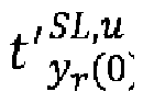 determining a PSFCH slot
 if the PSFCH slot
 the PSFCH slot

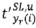
 the PSFCH slot


- User equipment, comprising:a processor; anda memory having instructions stored therein,wherein the instructions, when run by the processor, perform the method according to claim 1.
Applications Claiming Priority (2)
| Application Number | Priority Date | Filing Date | Title |
|---|---|---|---|
| CN202110883508.0A CN115706628A (en) | 2021-08-02 | 2021-08-02 | Method performed by user equipment and user equipment |
| PCT/CN2022/108934 WO2023011344A1 (en) | 2021-08-02 | 2022-07-29 | Method executed by user equipment, and user equipment |
Publications (2)
| Publication Number | Publication Date |
|---|---|
| EP4383623A1 true EP4383623A1 (en) | 2024-06-12 |
| EP4383623A4 EP4383623A4 (en) | 2025-04-30 |
Family
ID=85154422
Family Applications (1)
| Application Number | Title | Priority Date | Filing Date |
|---|---|---|---|
| EP22852057.3A Pending EP4383623A4 (en) | 2021-08-02 | 2022-07-29 | PROCEDURE PERFORMED BY A USER DEVICE AND USER DEVICE |
Country Status (4)
| Country | Link |
|---|---|
| US (1) | US20240334454A1 (en) |
| EP (1) | EP4383623A4 (en) |
| CN (1) | CN115706628A (en) |
| WO (1) | WO2023011344A1 (en) |
Families Citing this family (1)
| Publication number | Priority date | Publication date | Assignee | Title |
|---|---|---|---|---|
| CN116368912A (en) * | 2021-04-14 | 2023-06-30 | Lg 电子株式会社 | Method and device for sending or receiving physical sidelink feedback channel in wireless communication system |
Family Cites Families (3)
| Publication number | Priority date | Publication date | Assignee | Title |
|---|---|---|---|---|
| WO2020092939A1 (en) * | 2018-11-02 | 2020-05-07 | Intel Corporation | Sidelink collision avoidance, harq feedback, and csi acquisition |
| CN112840586B (en) * | 2021-01-14 | 2023-06-30 | 北京小米移动软件有限公司 | Communication method, communication device, and storage medium |
| CN112512124B (en) * | 2021-02-03 | 2021-07-09 | 之江实验室 | Method for determining side link transmission resource |
-
2021
- 2021-08-02 CN CN202110883508.0A patent/CN115706628A/en active Pending
-
2022
- 2022-07-29 EP EP22852057.3A patent/EP4383623A4/en active Pending
- 2022-07-29 US US18/293,680 patent/US20240334454A1/en active Pending
- 2022-07-29 WO PCT/CN2022/108934 patent/WO2023011344A1/en not_active Ceased
Also Published As
| Publication number | Publication date |
|---|---|
| WO2023011344A1 (en) | 2023-02-09 |
| US20240334454A1 (en) | 2024-10-03 |
| CN115706628A (en) | 2023-02-17 |
| EP4383623A4 (en) | 2025-04-30 |
Similar Documents
| Publication | Publication Date | Title |
|---|---|---|
| EP3863319A1 (en) | Method executed by user device and user device | |
| US20240080866A1 (en) | Method performed by user equipment, and user equipment | |
| CN110463327A (en) | Signaling downlink control information in a wireless communication network | |
| EP4187999B1 (en) | Method performed by user equipment, and user equipment | |
| EP3474594A1 (en) | Method and device for transmitting data on unlicensed spectrum | |
| EP4597899A1 (en) | Method executed by user equipment, and user equipment | |
| US20240389123A1 (en) | Method performed by user equipment, and user equipment | |
| EP4319216A1 (en) | Method executed by user equipment, and user equipment | |
| EP4376448A1 (en) | Method executed by user equipment, and user equipment | |
| EP4572396A1 (en) | Method executed by user equipment and user equipment | |
| EP4546913A1 (en) | Method executed by user equipment and user equipment | |
| EP4131826B1 (en) | Method implemented by user equipment, and user equipment | |
| EP4383623A1 (en) | Method executed by user equipment, and user equipment | |
| US20250274953A1 (en) | Method performed by user equipment, and user equipment | |
| US20250159698A1 (en) | Method performed by user equipment, and user equipment | |
| EP4514003A1 (en) | Method executed by user equipment, and user equipment | |
| CN116095628A (en) | Method performed by user equipment and user equipment | |
| EP4412356A1 (en) | Method performed by user equipment, and user equipment | |
| US12395989B2 (en) | Method performed by user equipment, and user equipment | |
| EP4191917A1 (en) | Method executed by user equipment, and user equipment | |
| EP4319221A1 (en) | Method implemented by user equipment, and user equipment | |
| EP4550926A1 (en) | Method executed by means of user equipment, and user equipment | |
| CN116095630A (en) | Method performed by user equipment and user equipment | |
| CN116095629A (en) | Method performed by user equipment and user equipment | |
| US20230379121A1 (en) | Method performed by user equipment, and user equipment |
Legal Events
| Date | Code | Title | Description |
|---|---|---|---|
| STAA | Information on the status of an ep patent application or granted ep patent |
Free format text: STATUS: THE INTERNATIONAL PUBLICATION HAS BEEN MADE |
|
| PUAI | Public reference made under article 153(3) epc to a published international application that has entered the european phase |
Free format text: ORIGINAL CODE: 0009012 |
|
| STAA | Information on the status of an ep patent application or granted ep patent |
Free format text: STATUS: REQUEST FOR EXAMINATION WAS MADE |
|
| 17P | Request for examination filed |
Effective date: 20240212 |
|
| AK | Designated contracting states |
Kind code of ref document: A1 Designated state(s): AL AT BE BG CH CY CZ DE DK EE ES FI FR GB GR HR HU IE IS IT LI LT LU LV MC MK MT NL NO PL PT RO RS SE SI SK SM TR |
|
| RIN1 | Information on inventor provided before grant (corrected) |
Inventor name: LIU, RENMAO Inventor name: ZHAO, YINAN Inventor name: LUO, CHAO |
|
| DAV | Request for validation of the european patent (deleted) | ||
| DAX | Request for extension of the european patent (deleted) | ||
| A4 | Supplementary search report drawn up and despatched |
Effective date: 20250327 |
|
| RIC1 | Information provided on ipc code assigned before grant |
Ipc: H04W 72/25 20230101ALI20250321BHEP Ipc: H04W 4/40 20180101ALI20250321BHEP Ipc: H04W 92/18 20090101ALI20250321BHEP Ipc: H04W 72/04 20230101ALI20250321BHEP Ipc: H04L 1/18 20230101ALI20250321BHEP Ipc: H04L 5/00 20060101AFI20250321BHEP |