EP4383530A1 - An electrical machine and a method for implementing a transportation support of the same - Google Patents
An electrical machine and a method for implementing a transportation support of the same Download PDFInfo
- Publication number
- EP4383530A1 EP4383530A1 EP22212319.2A EP22212319A EP4383530A1 EP 4383530 A1 EP4383530 A1 EP 4383530A1 EP 22212319 A EP22212319 A EP 22212319A EP 4383530 A1 EP4383530 A1 EP 4383530A1
- Authority
- EP
- European Patent Office
- Prior art keywords
- electrical machine
- rotor
- shaft
- generating device
- force generating
- Prior art date
- Legal status (The legal status is an assumption and is not a legal conclusion. Google has not performed a legal analysis and makes no representation as to the accuracy of the status listed.)
- Granted
Links
Images


Classifications
-
- H—ELECTRICITY
- H02—GENERATION; CONVERSION OR DISTRIBUTION OF ELECTRIC POWER
- H02K—DYNAMO-ELECTRIC MACHINES
- H02K5/00—Casings; Enclosures; Supports
- H02K5/04—Casings or enclosures characterised by the shape, form or construction thereof
- H02K5/16—Means for supporting bearings, e.g. insulating supports or means for fitting bearings in the bearing-shields
-
- F—MECHANICAL ENGINEERING; LIGHTING; HEATING; WEAPONS; BLASTING
- F16—ENGINEERING ELEMENTS AND UNITS; GENERAL MEASURES FOR PRODUCING AND MAINTAINING EFFECTIVE FUNCTIONING OF MACHINES OR INSTALLATIONS; THERMAL INSULATION IN GENERAL
- F16C—SHAFTS; FLEXIBLE SHAFTS; ELEMENTS OR CRANKSHAFT MECHANISMS; ROTARY BODIES OTHER THAN GEARING ELEMENTS; BEARINGS
- F16C19/00—Bearings with rolling contact, for exclusively rotary movement
- F16C19/02—Bearings with rolling contact, for exclusively rotary movement with bearing balls essentially of the same size in one or more circular rows
- F16C19/04—Bearings with rolling contact, for exclusively rotary movement with bearing balls essentially of the same size in one or more circular rows for radial load mainly
- F16C19/06—Bearings with rolling contact, for exclusively rotary movement with bearing balls essentially of the same size in one or more circular rows for radial load mainly with a single row or balls
-
- F—MECHANICAL ENGINEERING; LIGHTING; HEATING; WEAPONS; BLASTING
- F16—ENGINEERING ELEMENTS AND UNITS; GENERAL MEASURES FOR PRODUCING AND MAINTAINING EFFECTIVE FUNCTIONING OF MACHINES OR INSTALLATIONS; THERMAL INSULATION IN GENERAL
- F16C—SHAFTS; FLEXIBLE SHAFTS; ELEMENTS OR CRANKSHAFT MECHANISMS; ROTARY BODIES OTHER THAN GEARING ELEMENTS; BEARINGS
- F16C19/00—Bearings with rolling contact, for exclusively rotary movement
- F16C19/02—Bearings with rolling contact, for exclusively rotary movement with bearing balls essentially of the same size in one or more circular rows
- F16C19/14—Bearings with rolling contact, for exclusively rotary movement with bearing balls essentially of the same size in one or more circular rows for both radial and axial load
- F16C19/16—Bearings with rolling contact, for exclusively rotary movement with bearing balls essentially of the same size in one or more circular rows for both radial and axial load with a single row of balls
- F16C19/163—Bearings with rolling contact, for exclusively rotary movement with bearing balls essentially of the same size in one or more circular rows for both radial and axial load with a single row of balls with angular contact
-
- F—MECHANICAL ENGINEERING; LIGHTING; HEATING; WEAPONS; BLASTING
- F16—ENGINEERING ELEMENTS AND UNITS; GENERAL MEASURES FOR PRODUCING AND MAINTAINING EFFECTIVE FUNCTIONING OF MACHINES OR INSTALLATIONS; THERMAL INSULATION IN GENERAL
- F16C—SHAFTS; FLEXIBLE SHAFTS; ELEMENTS OR CRANKSHAFT MECHANISMS; ROTARY BODIES OTHER THAN GEARING ELEMENTS; BEARINGS
- F16C19/00—Bearings with rolling contact, for exclusively rotary movement
- F16C19/22—Bearings with rolling contact, for exclusively rotary movement with bearing rollers essentially of the same size in one or more circular rows, e.g. needle bearings
- F16C19/34—Bearings with rolling contact, for exclusively rotary movement with bearing rollers essentially of the same size in one or more circular rows, e.g. needle bearings for both radial and axial load
- F16C19/38—Bearings with rolling contact, for exclusively rotary movement with bearing rollers essentially of the same size in one or more circular rows, e.g. needle bearings for both radial and axial load with two or more rows of rollers
-
- F—MECHANICAL ENGINEERING; LIGHTING; HEATING; WEAPONS; BLASTING
- F16—ENGINEERING ELEMENTS AND UNITS; GENERAL MEASURES FOR PRODUCING AND MAINTAINING EFFECTIVE FUNCTIONING OF MACHINES OR INSTALLATIONS; THERMAL INSULATION IN GENERAL
- F16C—SHAFTS; FLEXIBLE SHAFTS; ELEMENTS OR CRANKSHAFT MECHANISMS; ROTARY BODIES OTHER THAN GEARING ELEMENTS; BEARINGS
- F16C23/00—Bearings for exclusively rotary movement adjustable for aligning or positioning
- F16C23/06—Ball or roller bearings
- F16C23/08—Ball or roller bearings self-adjusting
- F16C23/082—Ball or roller bearings self-adjusting by means of at least one substantially spherical surface
- F16C23/086—Ball or roller bearings self-adjusting by means of at least one substantially spherical surface forming a track for rolling elements
-
- F—MECHANICAL ENGINEERING; LIGHTING; HEATING; WEAPONS; BLASTING
- F16—ENGINEERING ELEMENTS AND UNITS; GENERAL MEASURES FOR PRODUCING AND MAINTAINING EFFECTIVE FUNCTIONING OF MACHINES OR INSTALLATIONS; THERMAL INSULATION IN GENERAL
- F16C—SHAFTS; FLEXIBLE SHAFTS; ELEMENTS OR CRANKSHAFT MECHANISMS; ROTARY BODIES OTHER THAN GEARING ELEMENTS; BEARINGS
- F16C25/00—Bearings for exclusively rotary movement adjustable for wear or play
- F16C25/06—Ball or roller bearings
- F16C25/08—Ball or roller bearings self-adjusting
- F16C25/083—Ball or roller bearings self-adjusting with resilient means acting axially on a race ring to preload the bearing
-
- F—MECHANICAL ENGINEERING; LIGHTING; HEATING; WEAPONS; BLASTING
- F16—ENGINEERING ELEMENTS AND UNITS; GENERAL MEASURES FOR PRODUCING AND MAINTAINING EFFECTIVE FUNCTIONING OF MACHINES OR INSTALLATIONS; THERMAL INSULATION IN GENERAL
- F16C—SHAFTS; FLEXIBLE SHAFTS; ELEMENTS OR CRANKSHAFT MECHANISMS; ROTARY BODIES OTHER THAN GEARING ELEMENTS; BEARINGS
- F16C41/00—Other accessories, e.g. devices integrated in the bearing not relating to the bearing function as such
- F16C41/04—Preventing damage to bearings during storage or transport thereof or when otherwise out of use
-
- F—MECHANICAL ENGINEERING; LIGHTING; HEATING; WEAPONS; BLASTING
- F16—ENGINEERING ELEMENTS AND UNITS; GENERAL MEASURES FOR PRODUCING AND MAINTAINING EFFECTIVE FUNCTIONING OF MACHINES OR INSTALLATIONS; THERMAL INSULATION IN GENERAL
- F16C—SHAFTS; FLEXIBLE SHAFTS; ELEMENTS OR CRANKSHAFT MECHANISMS; ROTARY BODIES OTHER THAN GEARING ELEMENTS; BEARINGS
- F16C2229/00—Setting preload
-
- F—MECHANICAL ENGINEERING; LIGHTING; HEATING; WEAPONS; BLASTING
- F16—ENGINEERING ELEMENTS AND UNITS; GENERAL MEASURES FOR PRODUCING AND MAINTAINING EFFECTIVE FUNCTIONING OF MACHINES OR INSTALLATIONS; THERMAL INSULATION IN GENERAL
- F16C—SHAFTS; FLEXIBLE SHAFTS; ELEMENTS OR CRANKSHAFT MECHANISMS; ROTARY BODIES OTHER THAN GEARING ELEMENTS; BEARINGS
- F16C2380/00—Electrical apparatus
- F16C2380/26—Dynamo-electric machines or combinations therewith, e.g. electro-motors and generators
Definitions
- the disclosure relates generally to electrical machines. More particularly, the disclosure relates to an electrical machine that comprises a stator, a rotor, bearings configured to rotatably support the rotor with respect to the stator, and means for implementing a transportation support for protecting the electrical machine against damaging when the electrical machine is transported or is otherwise subject to external vibrations and/or impacts at standstill. Furthermore, the disclosure relates to a method for implementing a transportation support of an electrical machine. Furthermore, the disclosure relates to an electric drive.
- a new electrical machine that comprises:
- the actuator is controlled to direct axial force to the end of a shaft to remove clearances from the bearings and thereby to prevent bearing surfaces from banging against each to protect the bearings against damaging.
- the electrical machine is used for its purpose as a motor or generator, the force generating device is advantageously in a mode where there is a physical air gap between the actuator and the end of the shaft.
- the above-mentioned force generating device can be a hydraulic device where the actuator comprises a hydraulic piston. It is also possible that the force generating device is a pneumatic device having a pneumatically driven actuator or an electrical device having a magnetically driven actuator. It is to be noted that embodiments of the invention are not limited to any specific way or ways to direct an axial force to an end of a shaft of an electrical machine.
- a new electric drive that comprises an electrical machine and a converter configured to drive the electrical machine.
- the electrical machine is an electrical machine according to an embodiment that comprises a status detection device configured to produce a status signal expressing whether the actuator directs an axial force to the end of the shaft of the rotor.
- the converter is configured to receive the status signal and to refrain from supplying voltage to the electrical machine when the actuator directs the axial force to the end of the shaft of the rotor to avoid an unintentional and possibly damaging starting of the electrical machine when the force generating device is active.
- the method according to the invention comprises directing an axial force to an end of a shaft of the rotor to remove clearances from the bearings with the aid of a force generating device mechanically attached to the stator and comprising an actuator configured to direct the axial force to the end of the shaft of the rotor.
- transportation support means a support arrangement that is applicable for protecting against damages during transportation as well as during other situations in which an electrical machine is at standstill and subject to external vibrations and/or impacts.
- FIG. 1 illustrates a part of an electrical machine 100 according to an exemplifying and non-limiting embodiment.
- the electrical machine 100 comprises a stator 101 and a rotor 102 that is rotatably supported with respect to the stator 101 and configured to electromagnetically interact with the stator to produce torque in response to currents supplied to the electrical machine.
- the electrical machine 100 can be for example an induction machine, a permanent magnet machine, a reluctance machine, or direct current "DC" machine.
- FIG 1 only the non-driving "ND" end of the electrical machine 100 is shown.
- the stator 101 is shown as a section view where the geometric section plane is parallel with the yz-plane of a coordinate system 199.
- the stator 102 comprises a stator core structure 118 and stator windings 119.
- the axial direction of the electrical machine 100 is parallel with the z-axis of the coordinate system 199.
- the electrical machine 100 comprises bearings configured to rotatably support the rotor 102 with respect to the stator 101.
- the bearing of the ND-end is denoted with a reference 103.
- the bearing 103 is a ball bearing.
- the bearing of the driving "D" end of the electrical machine 100 can be a ball bearing.
- the bearing of the D-end is not shown in figure 1 .
- the electrical machine 100 comprises a force generating device 104 that is mechanically attached to the stator 101 and comprises an actuator 105 configured to direct an axial force to an end of a shaft 106 of the rotor 102 to remove clearances from the bearings of the electrical machine 100.
- the end of the shaft 106 is shown as a section view where the geometric section plane is parallel with the yz-plane of the coordinate system 199.
- the force generating device is at the ND-end of the electrical machine.
- a force generating device is configured to direct an axial force to an end of a shaft at the D-end of the electrical machine.
- the force generating device 104 is a hydraulic device that comprises a hydraulic cylinder 107 and the actuator 105 of the force generating device 104 comprises a hydraulic piston 108.
- the hydraulic cylinder 107 is shown as a section view where the geometric section plane is parallel with the yz-plane of the coordinate system 199.
- the hydraulic cylinder 107 is a single-action hydraulic cylinder capable of pushing the hydraulic piston 108 towards the end of the shaft 106 of the rotor in the negative z-direction of the coordinate system 199.
- the force generating device 104 comprises a return spring 109 configured to push the hydraulic piston away from the end of the shaft 106 of the rotor in the positive z-direction of the coordinate system 199.
- a force generating device of an electrical machine according to an exemplifying and non-limiting embodiment is an electromagnetic device comprising an electromagnet for generating an axial force directed to an end of a shaft of the electrical machine.
- a force generating device of an electrical machine according to an exemplifying and non-limiting embodiment is a pneumatic device comprising a pneumatically driven actuator for generating an axial force directed to an end of a shaft of the electrical machine.
- the force generating device 104 comprises a pressurizer 110 that is capable of maintaining pressure of hydraulic fluid without external energy for example when the electrical machine 100 is transported or is otherwise subject to external vibrations and/or impacts and no external energy is available.
- the pressurizer 110 comprises a body and a flexible bag 120 inside the body and containing the hydraulic fluid.
- the force generating device 104 is activated by pumping compressed flexible material 111, e.g. air or other gas, into the room between the body and the flexible bag 120.
- the flexible material 111 directs pressure to the flexible bag 120 and thereby maintains the pressure of hydraulic fluid.
- the force generating device 104 is deactivated by allowing the pressure of the flexible material 111 to drop down.
- different means for controlling the force generating device 104 are possible, e.g. an electrically driven hydraulic pump, a spring operated pressurizer, etc.
- the force generating device 104 comprises a collar section 112 attached to a bearing shield 113 of the electrical machine 100 and a flange section 114 connecting to the collar section.
- the collar section 112 and the flange section 114 are shown as section views where the geometric section plane is parallel with the yz-plane of the coordinate system 199.
- the hydraulic cylinder 107 is attached to the flange section 114 and the actuator 105 protrudes towards the end of the shaft 106 of the rotor via an aperture of the flange section 114.
- the exemplifying electrical machine 100 illustrated in figure 1 comprises a protector element 117 between the actuator 105 of the force generating device 104 and the end of the shaft 106 of the rotor.
- the protector element 117 is shown as a section view where the geometric section plane is parallel with the yz-plane of the coordinate system 199.
- the protector element 117 is made of material softer than material of the shaft 106 of the rotor and protects the shaft of the rotor from shape deformations.
- the protector element 117 can be made of e.g. aluminum or nylon.
- An electrical machine comprises a status detection device 115 configured to produce a status signal 116 that directly or indirectly expresses whether the actuator 105 directs an axial force to the end of the shaft 106 of the rotor 102.
- the status detection device 115 comprises a pressure sensor configured to detect the pressure of the hydraulic fluid and to produce the status signal 116 in accordance with the detected pressure.
- the status detection device of an electrical machine comprises a position sensor configured to detect the axial position of the actuator of the force generating device, or a mechanical sensor such as a strain gauge configured to detect mechanical stress or deformation in the actuator or in some other appropriate part of the force generating device.
- the status detection device may comprise a device for generating the status signal based on electric current of the electromagnetic force generating device.
- the status detection device may comprise e.g.
- pressurized gas e.g. air
- the above-mentioned status signal can be produced in many ways, and the embodiments of the invention are not limited to any specific way or ways to produce the status signal.
- the above-mentioned status signal 116 is advantageous in an electric drive that comprises the electrical machine 100 and a converter 132 configured to drive the electrical machine 100.
- the converter 132 is configured to receive the status signal 116 and to refrain from supplying voltage to the electrical machine 100 when the actuator 105 directs the axial force to the end of the shaft 106 to avoid an unintentional and possibly damaging starting of the electrical machine 100 when the force generating device 104 is active.
- the status signal 116 can be used as a feedback signal supplied to a control device that is configured to control the force generating device.
- the feedback signal can be used for e.g. monitoring that the force generating device works correctly in response to control actions carried out by the control device. Concealed incorrect operation of the force generating device may lead to bearing damages during transportation as well as during other situations in which the electrical machine is at standstill and subject to external vibrations and/or impacts.
- the feedback signal can be used for generating an alarm in a case of incorrect operation of the force generating device.
- An electrical machine comprises a control device 150 configured to control the force generating device, to receive the status signal 116, and to generate an alarm in response to a situation in which i) the force generating device has been controlled to direct the axial force to the end of the shaft but ii) the status signal 116 expresses that no axial force is directed to the end of the shaft.
- FIG. 2 illustrates a part of an electrical machine 200 according to an exemplifying and non-limiting embodiment.
- the electrical machine 200 comprises a stator 201 and a rotor 202 that is rotatably supported with respect to the stator 201 and configured to electromagnetically interact with the stator to produce torque in response to currents supplied to the electrical machine.
- the stator 201 is shown as a section view where the geometric section plane is parallel with the yz-plane of a coordinate system 299.
- the stator 202 comprises a stator core structure 218 and stator windings 219.
- the axial direction of the electrical machine 200 is parallel with the z-axis of the coordinate system 299.
- the electrical machine 200 comprises bearings configured to rotatably support the rotor 202 with respect to the stator 201.
- the bearing of the ND-end is denoted with a reference 203.
- the bearing 203 is a spherical roller bearing.
- the bearing of the driving "D" end of the electrical machine 200 can be a spherical roller bearing.
- the bearing of the D-end is not shown in figure 2 .
- the electrical machine 200 comprises a force generating device 204 that is mechanically attached to the stator 201 and comprises an actuator 205 configured to direct an axial force to an end of a shaft 206 of the rotor 202 to remove clearances from the bearings of the electrical machine 200.
- the end of the shaft 206 is shown as a section view where the geometric section plane is parallel with the yz-plane of the coordinate system 299.
- the force generating device is at the ND-end of the electrical machine.
- the force generating device 204 comprises a hydraulic cylinder 207 and the actuator 205 of the force generating device comprises a hydraulic piston 208.
- the hydraulic cylinder 207 is shown as a section view where the geometric section plane is parallel with the yz-plane of the coordinate system 299.
- the hydraulic cylinder 207 is a double-action hydraulic cylinder capable of pushing the hydraulic piston 208 towards the end of the shaft 206 of the rotor in the negative z-direction of the coordinate system 299, and capable of moving the hydraulic piston away from the end of the shaft of the rotor in the positive z-direction of the coordinate system 299.
- the force generating device 204 comprises pressurizers 210 and 230 which are capable of maintaining pressures of hydraulic fluids in different compartments of the hydraulic cylinder 207 without external energy.
- each of the pressurizers 210 and 230 comprises a body and a flexible bag inside the body and containing the hydraulic fluid.
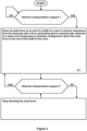
- Figure 3 shows a flowchart of a method according to an exemplifying and non-limiting embodiment for implementing a transportation support for an electrical machine that comprises a stator, a rotor rotatably supported with respect to the stator and configured to electromagnetically interact with the stator to produce torque in response to electric current supplied to the electrical machine, and bearings configured to rotatably support the rotor with respect to the stator.
- the method comprises directing 301 an axial force to an end of a shaft of the rotor to remove clearances from the bearings with the aid of a force generating device mechanically attached to the stator and comprising an actuator configured to direct the axial force to the end of the shaft of the rotor.
- the force generating device comprises a hydraulic cylinder and the actuator of the force generating device comprises a hydraulic piston.
- the hydraulic cylinder is a double-action hydraulic cylinder capable of pushing the hydraulic piston towards the end of the shaft of the rotor and capable of moving the hydraulic piston away from the end of the shaft of the rotor.
- the hydraulic cylinder is a single-action hydraulic cylinder capable of pushing the hydraulic piston towards the end of the shaft of the rotor
- the force generating device comprises a return spring configured to push the hydraulic piston away from the end of the shaft of the rotor.
- a method according to an exemplifying and non-limiting embodiment comprises maintaining pressure of hydraulic fluid with an aid of flexible material, e.g. air, being compressed and tending to return to an uncompressed state.
- an aid of flexible material e.g. air
- a method comprises use of a protector element between the actuator of the force generating device and the end of the shaft of the rotor.
- the protector element is made of material, e.g. aluminum or nylon, softer than material of the shaft of the rotor and protects the shaft of the rotor from shape deformations.
- a method comprises producing the status signal expressing whether the actuator directs the axial force to the end of the shaft of the rotor, and generating an alarm in response to a situation in which i) the force generating device has been controlled to direct the axial force to the end of the shaft but ii) the status signal expresses that no axial force is directed to the end of the shaft.
Landscapes
- Engineering & Computer Science (AREA)
- General Engineering & Computer Science (AREA)
- Mechanical Engineering (AREA)
- Power Engineering (AREA)
- Motor Or Generator Frames (AREA)
- Connection Of Motors, Electrical Generators, Mechanical Devices, And The Like (AREA)
- Rolling Contact Bearings (AREA)
- Manufacture Of Motors, Generators (AREA)
Abstract
Description
- The disclosure relates generally to electrical machines. More particularly, the disclosure relates to an electrical machine that comprises a stator, a rotor, bearings configured to rotatably support the rotor with respect to the stator, and means for implementing a transportation support for protecting the electrical machine against damaging when the electrical machine is transported or is otherwise subject to external vibrations and/or impacts at standstill. Furthermore, the disclosure relates to a method for implementing a transportation support of an electrical machine. Furthermore, the disclosure relates to an electric drive.
- While an electrical machine is at standstill and the electrical machine is transported as such or as a part of an application system, such as a working machine, by using a trailer, truck, locomotive, or ship, there is a possibility to damage the bearings of the electrical machine. Especially, in large electrical machines with substantially higher rotor masses, the bearings are at a significant risk to damage due to external vibration and impacts if not properly protected. The reason for the possible damages is that all rolling element bearings have a clearance to be able to be lubricated and to rotate with a low rolling resistance. Thus, external vibration and impacts may cause situation in which bearing surfaces bang against each other and get thereby damaged.
- To avoid bearing damages of the kind mentioned above, there is a need to mechanically support the rotor of an electrical machine so that bearing surfaces are prevented from banging against each other when the electrical machine is transported or is otherwise subject to external vibrations and/or impacts at standstill. Arranging a sufficient mechanical support can be especially challenging when an electrical machine is a part of an application system, such as a working machine, which is being transported or is otherwise subject to external vibrations and/or impacts.
- The following presents a simplified summary to provide a basic understanding of some aspects of various embodiments. The summary is not an extensive overview of the invention. It is neither intended to identify key or critical elements of the invention nor to delineate the scope of the invention. The following summary merely presents some concepts of the invention in a simplified form as a prelude to a more detailed description of exemplifying embodiments.
- In accordance with the invention, there is provided a new electrical machine that comprises:
- a stator,
- a rotor rotatably supported with respect to the stator and configured to electromagnetically interact with the stator to produce torque in response to one or more electric currents supplied to the electrical machine,
- bearings configured to rotatably support the rotor with respect to the stator, and
- a force generating device mechanically attached to the stator and comprising an actuator configured to direct an axial force to an end of a shaft of the rotor to remove clearances from the bearings.
- While the above-described electrical machine is transported or is otherwise subject to external vibrations and/or impacts at standstill, the actuator is controlled to direct axial force to the end of a shaft to remove clearances from the bearings and thereby to prevent bearing surfaces from banging against each to protect the bearings against damaging. While the electrical machine is used for its purpose as a motor or generator, the force generating device is advantageously in a mode where there is a physical air gap between the actuator and the end of the shaft.
- In the above-described electrical machine, the fact that many bearings providing radial support can withstand also axial loads is utilized to support the rotor when the electrical machine is being transported or is otherwise subject to external vibrations and/or impacts at standstill. For example, rolling elements with round or convex shapes naturally remove a radial clearance when an outer race of a bearing is displaced axially from an inner race of the bearing.
- The above-mentioned force generating device can be a hydraulic device where the actuator comprises a hydraulic piston. It is also possible that the force generating device is a pneumatic device having a pneumatically driven actuator or an electrical device having a magnetically driven actuator. It is to be noted that embodiments of the invention are not limited to any specific way or ways to direct an axial force to an end of a shaft of an electrical machine.
- In accordance with the invention, there is also provided a new electric drive that comprises an electrical machine and a converter configured to drive the electrical machine. The electrical machine is an electrical machine according to an embodiment that comprises a status detection device configured to produce a status signal expressing whether the actuator directs an axial force to the end of the shaft of the rotor. The converter is configured to receive the status signal and to refrain from supplying voltage to the electrical machine when the actuator directs the axial force to the end of the shaft of the rotor to avoid an unintentional and possibly damaging starting of the electrical machine when the force generating device is active.
- In accordance with the invention, there is also provided a new method for implementing a transportation support for an electrical machine that comprises:
- a stator,
- a rotor rotatably supported with respect to the stator and configured to electromagnetically interact with the stator to produce torque in response to electric current supplied to the electrical machine, and
- bearings configured to rotatably support the rotor with respect to the stator.
- The method according to the invention comprises directing an axial force to an end of a shaft of the rotor to remove clearances from the bearings with the aid of a force generating device mechanically attached to the stator and comprising an actuator configured to direct the axial force to the end of the shaft of the rotor.
- In this document, the term "transportation support" means a support arrangement that is applicable for protecting against damages during transportation as well as during other situations in which an electrical machine is at standstill and subject to external vibrations and/or impacts.
- Exemplifying and non-limiting embodiments are described in accompanied dependent claims.
- Exemplifying and non-limiting embodiments both as to constructions and to methods of operation, together with additional objects and advantages thereof, will be best understood from the following description of specific exemplifying and non-limiting embodiments when read in conjunction with the accompanying drawings.
- The verbs "to comprise" and "to include" are used in this document as open limitations that neither exclude nor require the existence of unrecited features.
- The features recited in dependent claims are mutually freely combinable unless otherwise explicitly stated.
- Furthermore, it is to be understood that the use of "a" or "an", i.e. a singular form, throughout this document does not exclude a plurality.
- Exemplifying and non-limiting embodiments and their advantages are explained in greater detail below in the sense of examples and with reference to the accompanying drawings, in which:
-
figure 1 illustrates an electrical machine according to an exemplifying and non-limiting embodiment, -
figure 2 illustrates an electrical machine according to an exemplifying and non-limiting embodiment, and -
figure 3 shows a flowchart of a method according to an exemplifying and non-limiting embodiment for implementing a transportation support for an electrical machine. - The specific examples provided in the description below should not be construed as limiting the scope and/or the applicability of the accompanied claims. Lists and groups of examples provided in the description are not exhaustive unless otherwise explicitly stated.
-
Figure 1 illustrates a part of anelectrical machine 100 according to an exemplifying and non-limiting embodiment. Theelectrical machine 100 comprises astator 101 and arotor 102 that is rotatably supported with respect to thestator 101 and configured to electromagnetically interact with the stator to produce torque in response to currents supplied to the electrical machine. Theelectrical machine 100 can be for example an induction machine, a permanent magnet machine, a reluctance machine, or direct current "DC" machine. Infigure 1 , only the non-driving "ND" end of theelectrical machine 100 is shown. Thestator 101 is shown as a section view where the geometric section plane is parallel with the yz-plane of acoordinate system 199. Thestator 102 comprises astator core structure 118 andstator windings 119. The axial direction of theelectrical machine 100 is parallel with the z-axis of thecoordinate system 199. Theelectrical machine 100 comprises bearings configured to rotatably support therotor 102 with respect to thestator 101. Infigure 1 , the bearing of the ND-end is denoted with areference 103. In this exemplifying case, thebearing 103 is a ball bearing. Correspondingly, the bearing of the driving "D" end of theelectrical machine 100 can be a ball bearing. The bearing of the D-end is not shown infigure 1 . - The
electrical machine 100 comprises aforce generating device 104 that is mechanically attached to thestator 101 and comprises anactuator 105 configured to direct an axial force to an end of ashaft 106 of therotor 102 to remove clearances from the bearings of theelectrical machine 100. Infigure 1 , the end of theshaft 106 is shown as a section view where the geometric section plane is parallel with the yz-plane of thecoordinate system 199. In this exemplifying case, the force generating device is at the ND-end of the electrical machine. It is however also possible that a force generating device is configured to direct an axial force to an end of a shaft at the D-end of the electrical machine. For example, there can be a gearwheel or a sheave attached to the end of the shaft of an electrical machine, and the force generating device is configured to direct an axial force to the end of the shaft that protrudes through the gearwheel or the sheave. - In the exemplifying
electrical machine 100 illustrated infigure 1 , theforce generating device 104 is a hydraulic device that comprises ahydraulic cylinder 107 and theactuator 105 of theforce generating device 104 comprises ahydraulic piston 108. Infigure 1 , thehydraulic cylinder 107 is shown as a section view where the geometric section plane is parallel with the yz-plane of the coordinatesystem 199. In this exemplifying case, thehydraulic cylinder 107 is a single-action hydraulic cylinder capable of pushing thehydraulic piston 108 towards the end of theshaft 106 of the rotor in the negative z-direction of the coordinatesystem 199. Theforce generating device 104 comprises areturn spring 109 configured to push the hydraulic piston away from the end of theshaft 106 of the rotor in the positive z-direction of the coordinatesystem 199. It is also possible that a force generating device of an electrical machine according to an exemplifying and non-limiting embodiment is an electromagnetic device comprising an electromagnet for generating an axial force directed to an end of a shaft of the electrical machine. Furthermore, it is also possible that a force generating device of an electrical machine according to an exemplifying and non-limiting embodiment is a pneumatic device comprising a pneumatically driven actuator for generating an axial force directed to an end of a shaft of the electrical machine. - In the exemplifying
electrical machine 100 illustrated infigure 1 , theforce generating device 104 comprises apressurizer 110 that is capable of maintaining pressure of hydraulic fluid without external energy for example when theelectrical machine 100 is transported or is otherwise subject to external vibrations and/or impacts and no external energy is available. In this exemplifying case, thepressurizer 110 comprises a body and aflexible bag 120 inside the body and containing the hydraulic fluid. Theforce generating device 104 is activated by pumping compressedflexible material 111, e.g. air or other gas, into the room between the body and theflexible bag 120. Theflexible material 111 directs pressure to theflexible bag 120 and thereby maintains the pressure of hydraulic fluid. Theforce generating device 104 is deactivated by allowing the pressure of theflexible material 111 to drop down. Depending on requirements and availability or non-availability of external energy, different means for controlling theforce generating device 104 are possible, e.g. an electrically driven hydraulic pump, a spring operated pressurizer, etc. - In the exemplifying
electrical machine 100 illustrated infigure 1 , theforce generating device 104 comprises acollar section 112 attached to abearing shield 113 of theelectrical machine 100 and aflange section 114 connecting to the collar section. Infigure 1 , thecollar section 112 and theflange section 114 are shown as section views where the geometric section plane is parallel with the yz-plane of the coordinatesystem 199. Thehydraulic cylinder 107 is attached to theflange section 114 and theactuator 105 protrudes towards the end of theshaft 106 of the rotor via an aperture of theflange section 114. - The exemplifying
electrical machine 100 illustrated infigure 1 comprises aprotector element 117 between theactuator 105 of theforce generating device 104 and the end of theshaft 106 of the rotor. Infigure 1 , theprotector element 117 is shown as a section view where the geometric section plane is parallel with the yz-plane of the coordinatesystem 199. Theprotector element 117 is made of material softer than material of theshaft 106 of the rotor and protects the shaft of the rotor from shape deformations. Theprotector element 117 can be made of e.g. aluminum or nylon. - An electrical machine according to an exemplifying and non-limiting embodiment comprises a
status detection device 115 configured to produce astatus signal 116 that directly or indirectly expresses whether theactuator 105 directs an axial force to the end of theshaft 106 of therotor 102. In the exemplifying electrical machine illustrated infigure 1 , thestatus detection device 115 comprises a pressure sensor configured to detect the pressure of the hydraulic fluid and to produce thestatus signal 116 in accordance with the detected pressure. It is also possible that the status detection device of an electrical machine according to an exemplifying and non-limiting embodiment comprises a position sensor configured to detect the axial position of the actuator of the force generating device, or a mechanical sensor such as a strain gauge configured to detect mechanical stress or deformation in the actuator or in some other appropriate part of the force generating device. In an exemplifying case, where the force generating device is an electromagnetic force generating device, the status detection device may comprise a device for generating the status signal based on electric current of the electromagnetic force generating device. In an exemplifying case, where the force generating device is a pneumatic force generating device, the status detection device may comprise e.g. a gas pressure sensor or a device for generating the status signal based on operation of means for supplying pressurized gas e.g. air to the pneumatic force generating device. It is to be noted that the above-mentioned status signal can be produced in many ways, and the embodiments of the invention are not limited to any specific way or ways to produce the status signal. - The above-mentioned
status signal 116 is advantageous in an electric drive that comprises theelectrical machine 100 and aconverter 132 configured to drive theelectrical machine 100. Theconverter 132 is configured to receive thestatus signal 116 and to refrain from supplying voltage to theelectrical machine 100 when theactuator 105 directs the axial force to the end of theshaft 106 to avoid an unintentional and possibly damaging starting of theelectrical machine 100 when theforce generating device 104 is active. - Furthermore, the
status signal 116 can be used as a feedback signal supplied to a control device that is configured to control the force generating device. The feedback signal can be used for e.g. monitoring that the force generating device works correctly in response to control actions carried out by the control device. Concealed incorrect operation of the force generating device may lead to bearing damages during transportation as well as during other situations in which the electrical machine is at standstill and subject to external vibrations and/or impacts. The feedback signal can be used for generating an alarm in a case of incorrect operation of the force generating device. An electrical machine according to an exemplifying and non-limiting embodiment comprises acontrol device 150 configured to control the force generating device, to receive thestatus signal 116, and to generate an alarm in response to a situation in which i) the force generating device has been controlled to direct the axial force to the end of the shaft but ii) thestatus signal 116 expresses that no axial force is directed to the end of the shaft. -
Figure 2 illustrates a part of anelectrical machine 200 according to an exemplifying and non-limiting embodiment. Theelectrical machine 200 comprises astator 201 and arotor 202 that is rotatably supported with respect to thestator 201 and configured to electromagnetically interact with the stator to produce torque in response to currents supplied to the electrical machine. Infigure 2 , only the non-driving "ND" end of theelectrical machine 200 is shown. Thestator 201 is shown as a section view where the geometric section plane is parallel with the yz-plane of a coordinatesystem 299. Thestator 202 comprises astator core structure 218 andstator windings 219. The axial direction of theelectrical machine 200 is parallel with the z-axis of the coordinatesystem 299. Theelectrical machine 200 comprises bearings configured to rotatably support therotor 202 with respect to thestator 201. Infigure 2 , the bearing of the ND-end is denoted with areference 203. In this exemplifying case, thebearing 203 is a spherical roller bearing. Correspondingly, the bearing of the driving "D" end of theelectrical machine 200 can be a spherical roller bearing. The bearing of the D-end is not shown infigure 2 . - The
electrical machine 200 comprises aforce generating device 204 that is mechanically attached to thestator 201 and comprises anactuator 205 configured to direct an axial force to an end of ashaft 206 of therotor 202 to remove clearances from the bearings of theelectrical machine 200. Infigure 2 , the end of theshaft 206 is shown as a section view where the geometric section plane is parallel with the yz-plane of the coordinatesystem 299. In this exemplifying case, the force generating device is at the ND-end of the electrical machine. Theforce generating device 204 comprises ahydraulic cylinder 207 and theactuator 205 of the force generating device comprises ahydraulic piston 208. Infigure 2 , thehydraulic cylinder 207 is shown as a section view where the geometric section plane is parallel with the yz-plane of the coordinatesystem 299. In this exemplifying case, thehydraulic cylinder 207 is a double-action hydraulic cylinder capable of pushing thehydraulic piston 208 towards the end of theshaft 206 of the rotor in the negative z-direction of the coordinatesystem 299, and capable of moving the hydraulic piston away from the end of the shaft of the rotor in the positive z-direction of the coordinatesystem 299. - In the exemplifying
electrical machine 200 illustrated infigure 2 , theforce generating device 204 comprisespressurizers hydraulic cylinder 207 without external energy. In this exemplifying case, each of thepressurizers -
Figure 3 shows a flowchart of a method according to an exemplifying and non-limiting embodiment for implementing a transportation support for an electrical machine that comprises a stator, a rotor rotatably supported with respect to the stator and configured to electromagnetically interact with the stator to produce torque in response to electric current supplied to the electrical machine, and bearings configured to rotatably support the rotor with respect to the stator. - The method comprises directing 301 an axial force to an end of a shaft of the rotor to remove clearances from the bearings with the aid of a force generating device mechanically attached to the stator and comprising an actuator configured to direct the axial force to the end of the shaft of the rotor.
- In a method according to an exemplifying and non-limiting embodiment, the force generating device comprises a hydraulic cylinder and the actuator of the force generating device comprises a hydraulic piston.
- In a method according to an exemplifying and non-limiting embodiment, the hydraulic cylinder is a double-action hydraulic cylinder capable of pushing the hydraulic piston towards the end of the shaft of the rotor and capable of moving the hydraulic piston away from the end of the shaft of the rotor.
- In a method according to an exemplifying and non-limiting embodiment, the hydraulic cylinder is a single-action hydraulic cylinder capable of pushing the hydraulic piston towards the end of the shaft of the rotor, and the force generating device comprises a return spring configured to push the hydraulic piston away from the end of the shaft of the rotor.
- A method according to an exemplifying and non-limiting embodiment comprises maintaining pressure of hydraulic fluid with an aid of flexible material, e.g. air, being compressed and tending to return to an uncompressed state.
- A method according to an exemplifying and non-limiting embodiment comprises use of a protector element between the actuator of the force generating device and the end of the shaft of the rotor. The protector element is made of material, e.g. aluminum or nylon, softer than material of the shaft of the rotor and protects the shaft of the rotor from shape deformations.
- A method according to an exemplifying and non-limiting embodiment comprises:
- producing a status signal expressing whether the actuator directs the axial force to the end of the shaft of the rotor,
- delivering the status signal to a converter configured to drive the electrical machine, and
- disabling the converter to supply voltage to the electrical machine when the status signal expresses that the actuator directs the axial force to the end of the shaft of the rotor.
- A method according to an exemplifying and non-limiting embodiment comprises producing the status signal expressing whether the actuator directs the axial force to the end of the shaft of the rotor, and generating an alarm in response to a situation in which i) the force generating device has been controlled to direct the axial force to the end of the shaft but ii) the status signal expresses that no axial force is directed to the end of the shaft.
- The specific examples provided in the description given above should not be construed as limiting the applicability and/or interpretation of the appended claims. It is to be noted that lists and groups of examples given in this document are non-exhaustive lists and groups unless otherwise explicitly stated.
Claims (17)
- An electrical machine (100, 200) comprising:- a stator (101, 201),- a rotor (102, 202) rotatably supported with respect to the stator and configured to electromagnetically interact with the stator to produce torque in response to one or more electric currents supplied to the electrical machine, and- bearings (103, 203) configured to rotatably support the rotor with respect to the stator,characterized in that the electrical machine further comprises a force generating device (104, 204) mechanically attached to the stator and comprising an actuator (105, 205) configured to direct an axial force to an end of a shaft (106, 206) of the rotor to remove clearances from the bearings.
- An electrical machine according to claim 1, wherein the force generating device (104, 204) comprises a hydraulic cylinder (107, 207) and the actuator (105, 205) of the force generating device comprises a hydraulic piston (108, 208).
- An electrical machine according to claim 2, wherein the hydraulic cylinder (207) is a double-action hydraulic cylinder capable of pushing the hydraulic piston (208) towards the end of the shaft of the rotor and capable of moving the hydraulic piston away from the end of the shaft of the rotor.
- An electrical machine according to claim 2, wherein the hydraulic cylinder (107) is a single-action hydraulic cylinder capable of pushing the hydraulic piston (108) towards the end of the shaft of the rotor, and the force generating device (104) comprises a return spring (109) configured to push the hydraulic piston away from the end of the shaft of the rotor.
- An electrical machine according to any one of claims 2-4, wherein the force generating device (104, 204) comprises a pressurizer (110, 210, 230) configured maintain pressure of hydraulic fluid with an aid of flexible material (111) being compressed and tending to return to an uncompressed state.
- An electrical machine according to any one of claims 2-5, wherein the force generating device (104, 204) comprises a collar section (112) attached to a bearing shield (113) of the electrical machine and a flange section (114) connecting to the collar section, the hydraulic cylinder (107, 207) being attached to the flange section and the actuator (105, 205) protruding towards the end of the shaft of the rotor via an aperture of the flange section.
- An electrical machine according to any one of claims 1-6, wherein the electrical machine comprises a protector element (117) between the actuator (105) of the force generating device (104) and the end of the shaft (106) of the rotor, the protector element being made of material softer than material of the shaft (106) of the rotor and protecting the shaft of the rotor from shape deformations.
- An electrical machine according to any one of claims 1-7, wherein the electrical machine comprises a status detection device (115) configured to produce a status signal (116) expressing whether the actuator (105, 205) directs the axial force to the end of the shaft (106, 206) of the rotor.
- An electrical machine according to claim 8, wherein the electrical machine comprises a control device (150) configured to control the force generating device (104), to receive the status signal (116), and to generate an alarm in response to a situation in which i) the force generating device has been controlled to direct the axial force to the end of the shaft but ii) the status signal (116) expresses that no axial force is directed to the end of the shaft.
- An electric drive that comprises:- an electrical machine (100), and- a converter (132) configured to drive the electrical machine,wherein the electrical machine (100) is an electrical machine according to claim 8 or 9, and the converter is configured to receive the status signal and to refrain from supplying voltage to the electrical machine when the status signal expresses that the actuator directs the axial force to the end of the shaft of the rotor.
- A method for implementing a transportation support for an electrical machine that comprises:- a stator (101, 201),- a rotor (102, 202) rotatably supported with respect to the stator and configured to electromagnetically interact with the stator to produce torque in response to electric current supplied to the electrical machine, and- bearings (103, 203) configured to rotatably support the rotor with respect to the stator,characterized in that the method comprises directing (301) an axial force to an end of a shaft (106, 206) of the rotor to remove clearances from the bearings with a force generating device (104, 204) mechanically attached to the stator and comprising an actuator (105, 205) configured to direct the axial force to the end of the shaft of the rotor.
- A method according to claim 11, wherein the force generating (104, 204) device comprises a hydraulic cylinder (107, 207) and the actuator (105, 205) of the force generating device comprises a hydraulic piston.
- A method according to claim 12, wherein the hydraulic cylinder (207) is a double-action hydraulic cylinder capable of pushing the hydraulic piston (208) towards the end of the shaft of the rotor and capable of moving the hydraulic piston away from the end of the shaft of the rotor.
- A method according to claim 13, wherein the hydraulic cylinder (107) is a single-action hydraulic cylinder capable of pushing the hydraulic piston towards the end of the shaft of the rotor, and the force generating device (104) comprises a return spring (109) configured to push the hydraulic piston away from the end of the shaft of the rotor.
- A method according to any one of claims 12-14, wherein the method comprises maintaining pressure of hydraulic fluid with an aid of flexible material (111) being compressed and tending to return to an uncompressed state.
- A method according to any one of claims 11-15, wherein the method comprises use of a protector element (117) between the actuator (205) of the force generating device (104) and the end of the shaft (106) of the rotor, the protector element being made of material softer than material of the shaft (106) of the rotor and protecting the shaft of the rotor from shape deformations.
- A method according to any one of claims 11-16, wherein the method comprises:- producing a status signal (116) expressing whether the actuator (105) directs the axial force to the end of the shaft (106) of the rotor,- delivering the status signal to a converter (132) configured to drive the electrical machine, and- disabling the converter to supply voltage to the electrical machine when the status signal expresses that the actuator directs the axial force to the end of the shaft of the rotor.
Priority Applications (5)
| Application Number | Priority Date | Filing Date | Title |
|---|---|---|---|
| EP22212319.2A EP4383530B1 (en) | 2022-12-08 | 2022-12-08 | An electrical machine and a method for implementing a transportation support of the same |
| JP2025533332A JP2025540299A (en) | 2022-12-08 | 2023-11-10 | Method for mounting an electric machine and its transport support |
| CN202380092493.3A CN120604436A (en) | 2022-12-08 | 2023-11-10 | Motor and method for achieving transport support thereof |
| KR1020257022117A KR20250121040A (en) | 2022-12-08 | 2023-11-10 | Electrical machines and methods for implementing transport support thereof |
| PCT/EP2023/081394 WO2024120740A1 (en) | 2022-12-08 | 2023-11-10 | An electrical machine and a method for implementing a transportation support of the same |
Applications Claiming Priority (1)
| Application Number | Priority Date | Filing Date | Title |
|---|---|---|---|
| EP22212319.2A EP4383530B1 (en) | 2022-12-08 | 2022-12-08 | An electrical machine and a method for implementing a transportation support of the same |
Publications (2)
| Publication Number | Publication Date |
|---|---|
| EP4383530A1 true EP4383530A1 (en) | 2024-06-12 |
| EP4383530B1 EP4383530B1 (en) | 2026-07-29 |
Family
ID=84462752
Family Applications (1)
| Application Number | Title | Priority Date | Filing Date |
|---|---|---|---|
| EP22212319.2A Active EP4383530B1 (en) | 2022-12-08 | 2022-12-08 | An electrical machine and a method for implementing a transportation support of the same |
Country Status (5)
| Country | Link |
|---|---|
| EP (1) | EP4383530B1 (en) |
| JP (1) | JP2025540299A (en) |
| KR (1) | KR20250121040A (en) |
| CN (1) | CN120604436A (en) |
| WO (1) | WO2024120740A1 (en) |
Citations (2)
| Publication number | Priority date | Publication date | Assignee | Title |
|---|---|---|---|---|
| US20150030277A1 (en) * | 2012-04-13 | 2015-01-29 | Eolotec Gmbh | Bearing arrangement of a wind turbine and method for adjusting the preload of a bearing arrangement |
| EP3537573A1 (en) * | 2018-03-06 | 2019-09-11 | Traktionssysteme Austria GmbH | Fixing element for fixing the rotor shaft of an electric machine to the stator and electric machine comprising such a fixing element |
-
2022
- 2022-12-08 EP EP22212319.2A patent/EP4383530B1/en active Active
-
2023
- 2023-11-10 KR KR1020257022117A patent/KR20250121040A/en active Pending
- 2023-11-10 CN CN202380092493.3A patent/CN120604436A/en active Pending
- 2023-11-10 WO PCT/EP2023/081394 patent/WO2024120740A1/en not_active Ceased
- 2023-11-10 JP JP2025533332A patent/JP2025540299A/en active Pending
Patent Citations (2)
| Publication number | Priority date | Publication date | Assignee | Title |
|---|---|---|---|---|
| US20150030277A1 (en) * | 2012-04-13 | 2015-01-29 | Eolotec Gmbh | Bearing arrangement of a wind turbine and method for adjusting the preload of a bearing arrangement |
| EP3537573A1 (en) * | 2018-03-06 | 2019-09-11 | Traktionssysteme Austria GmbH | Fixing element for fixing the rotor shaft of an electric machine to the stator and electric machine comprising such a fixing element |
Also Published As
| Publication number | Publication date |
|---|---|
| CN120604436A (en) | 2025-09-05 |
| WO2024120740A1 (en) | 2024-06-13 |
| JP2025540299A (en) | 2025-12-11 |
| EP4383530B1 (en) | 2026-07-29 |
| KR20250121040A (en) | 2025-08-11 |
Similar Documents
| Publication | Publication Date | Title |
|---|---|---|
| US7964982B2 (en) | Axial in-line turbomachine | |
| CN101334068B (en) | Method and device for starting an electric machine with a rotor, being magnetically supported | |
| US11585235B2 (en) | Magnetic shaft mode control | |
| US7564662B2 (en) | Overload protection system for an electromagnetic lift | |
| EP2763292A1 (en) | High speed flywheel on magnetic bearings | |
| EP2677176B1 (en) | Compact electric centrifugal compressor | |
| EP0526903A1 (en) | Bearing device | |
| EP2677177B1 (en) | Electric centrifugal compressor for vehicles | |
| CN101707409B (en) | Ct scanner gantry with aerostatic bearing and segmented ring motor | |
| US8283826B2 (en) | Bearing arrangement and bearing block having a magnetic radial bearing and a touchdown bearing for a rotating machine | |
| US8531071B2 (en) | Turbine engine powered system with hybrid bearing | |
| WO1996019034A1 (en) | Electromagnetic-coupled/levitated apparatus and method for rotating equipment | |
| US20040022653A1 (en) | Rotary machine with axial stop incorporating a current generator | |
| WO1996019034A9 (en) | Electromagnetic-coupled/levitated apparatus and method for rotating equipment | |
| WO2012061011A2 (en) | System and apparatus for reducing thrust forces acting on a compressor rotor | |
| KR20150079653A (en) | Vacuum pump | |
| EP4520986A1 (en) | Air cycle machine (acm) with hybrid airfoil and auxiliary magnetic thrust bearings | |
| EP2390511A1 (en) | Additional support for AMB supported rotors by means of permanent magnet bearings | |
| WO2024120740A1 (en) | An electrical machine and a method for implementing a transportation support of the same | |
| EP3780380A1 (en) | Electric motor system, and turbo compressor provided with same | |
| KR20210037693A (en) | Actuator | |
| CN112088487B (en) | Motor system and turbo compressor including the same | |
| JP2005168190A (en) | Variable air gap type permanent magnet motor | |
| CN108825527B (en) | Magnetic suspension refrigeration compressor | |
| US20160222987A1 (en) | Hydraulic accumulator and method for recovering energy in a hydraulic system |
Legal Events
| Date | Code | Title | Description |
|---|---|---|---|
| PUAI | Public reference made under article 153(3) epc to a published international application that has entered the european phase |
Free format text: ORIGINAL CODE: 0009012 |
|
| STAA | Information on the status of an ep patent application or granted ep patent |
Free format text: STATUS: THE APPLICATION HAS BEEN PUBLISHED |
|
| AK | Designated contracting states |
Kind code of ref document: A1 Designated state(s): AL AT BE BG CH CY CZ DE DK EE ES FI FR GB GR HR HU IE IS IT LI LT LU LV MC ME MK MT NL NO PL PT RO RS SE SI SK SM TR |
|
| STAA | Information on the status of an ep patent application or granted ep patent |
Free format text: STATUS: REQUEST FOR EXAMINATION WAS MADE |
|
| 17P | Request for examination filed |
Effective date: 20240925 |
|
| RBV | Designated contracting states (corrected) |
Designated state(s): AL AT BE BG CH CY CZ DE DK EE ES FI FR GB GR HR HU IE IS IT LI LT LU LV MC ME MK MT NL NO PL PT RO RS SE SI SK SM TR |
|
| GRAP | Despatch of communication of intention to grant a patent |
Free format text: ORIGINAL CODE: EPIDOSNIGR1 |
|
| STAA | Information on the status of an ep patent application or granted ep patent |
Free format text: STATUS: GRANT OF PATENT IS INTENDED |
|
| GRAS | Grant fee paid |
Free format text: ORIGINAL CODE: EPIDOSNIGR3 |
|
| INTG | Intention to grant announced |
Effective date: 20260520 |
|
| GRAA | (expected) grant |
Free format text: ORIGINAL CODE: 0009210 |
|
| STAA | Information on the status of an ep patent application or granted ep patent |
Free format text: STATUS: THE PATENT HAS BEEN GRANTED |
|
| P01 | Opt-out of the competence of the unified patent court (upc) registered |
Free format text: CASE NUMBER: UPC_APP_0018622_4383530/2026 Effective date: 20260615 |
|
| AK | Designated contracting states |
Kind code of ref document: B1 Designated state(s): AL AT BE BG CH CY CZ DE DK EE ES FI FR GB GR HR HU IE IS IT LI LT LU LV MC ME MK MT NL NO PL PT RO RS SE SI SK SM TR |
|
| REG | Reference to a national code |
Ref country code: CH Ref legal event code: F10 Free format text: ST27 STATUS EVENT CODE: U-0-0-F10-F00 (AS PROVIDED BY THE NATIONAL OFFICE) Effective date: 20260729 |