EP4383506A2 - Apparatus, method and system for detecting an islanding state of a power generation device - Google Patents
Apparatus, method and system for detecting an islanding state of a power generation device Download PDFInfo
- Publication number
- EP4383506A2 EP4383506A2 EP23307015.0A EP23307015A EP4383506A2 EP 4383506 A2 EP4383506 A2 EP 4383506A2 EP 23307015 A EP23307015 A EP 23307015A EP 4383506 A2 EP4383506 A2 EP 4383506A2
- Authority
- EP
- European Patent Office
- Prior art keywords
- power generation
- generation device
- voltage
- phasor
- substation
- Prior art date
- Legal status (The legal status is an assumption and is not a legal conclusion. Google has not performed a legal analysis and makes no representation as to the accuracy of the status listed.)
- Pending
Links
Images


Classifications
-
- G—PHYSICS
- G01—MEASURING; TESTING
- G01R—MEASURING ELECTRIC VARIABLES; MEASURING MAGNETIC VARIABLES
- G01R31/00—Arrangements for testing electric properties; Arrangements for locating electric faults; Arrangements for electrical testing characterised by what is being tested not provided for elsewhere
- G01R31/40—Testing power supplies
- G01R31/42—AC power supplies
-
- H—ELECTRICITY
- H02—GENERATION; CONVERSION OR DISTRIBUTION OF ELECTRIC POWER
- H02J—ELECTRIC POWER NETWORKS; CIRCUIT ARRANGEMENTS OR SYSTEMS FOR SUPPLYING OR DISTRIBUTING ELECTRIC POWER; SYSTEMS FOR STORING ELECTRIC ENERGY
- H02J3/00—Circuit arrangements for AC mains or AC distribution networks
- H02J3/38—Arrangements for feeding a single network from two or more generators or sources in parallel; Arrangements for feeding already energised networks from additional generators or sources in parallel
- H02J3/388—Arrangements for the handling of islanding, e.g. for disconnection or for avoiding the disconnection of power
-
- G—PHYSICS
- G01—MEASURING; TESTING
- G01R—MEASURING ELECTRIC VARIABLES; MEASURING MAGNETIC VARIABLES
- G01R31/00—Arrangements for testing electric properties; Arrangements for locating electric faults; Arrangements for electrical testing characterised by what is being tested not provided for elsewhere
- G01R31/08—Locating faults in cables, transmission lines, or networks
- G01R31/081—Locating faults in cables, transmission lines, or networks according to type of conductors
- G01R31/086—Locating faults in cables, transmission lines, or networks according to type of conductors in power transmission or distribution networks, i.e. with interconnected conductors
-
- G—PHYSICS
- G01—MEASURING; TESTING
- G01R—MEASURING ELECTRIC VARIABLES; MEASURING MAGNETIC VARIABLES
- G01R19/00—Arrangements for measuring currents or voltages or for indicating presence or sign thereof
- G01R19/25—Arrangements for measuring currents or voltages or for indicating presence or sign thereof using digital measurement techniques
- G01R19/2513—Arrangements for monitoring electric power systems, e.g. power lines or loads; Logging
-
- H—ELECTRICITY
- H02—GENERATION; CONVERSION OR DISTRIBUTION OF ELECTRIC POWER
- H02J—ELECTRIC POWER NETWORKS; CIRCUIT ARRANGEMENTS OR SYSTEMS FOR SUPPLYING OR DISTRIBUTING ELECTRIC POWER; SYSTEMS FOR STORING ELECTRIC ENERGY
- H02J13/00—Circuit arrangements for providing remote monitoring or remote control of equipment in a power distribution network
- H02J13/12—Monitoring network conditions, e.g. electrical magnitudes or operational status
-
- H—ELECTRICITY
- H02—GENERATION; CONVERSION OR DISTRIBUTION OF ELECTRIC POWER
- H02J—ELECTRIC POWER NETWORKS; CIRCUIT ARRANGEMENTS OR SYSTEMS FOR SUPPLYING OR DISTRIBUTING ELECTRIC POWER; SYSTEMS FOR STORING ELECTRIC ENERGY
- H02J3/00—Circuit arrangements for AC mains or AC distribution networks
- H02J3/001—Arrangements for handling faults or abnormalities, e.g. emergencies or contingencies
- H02J3/0012—Arrangements for handling faults or abnormalities, e.g. emergencies or contingencies characterised by the contingency detection means in AC networks, e.g. using phasor measurement units [PMU], synchrophasors or contingency analysis
Definitions
- the present disclosure relates to an apparatus for detecting an islanding state of a power generation device, a method for detecting an islanding state of a power generation device, and a system for detecting an islanding state of a power generation device.
- Islanding means that when a power supply interruption happens on a main power grid side, a power generation device fails to detect the disconnection from the main power grid in time and therefore does not stop operating, making the power generation device and its nearby loads form a self-sufficient island power grid.
- the island power grid cannot be controlled by the operator of the main power grid. In the islanding state, there may be a significant rated voltage offset and a rated frequency offset, which will lead to abnormal operation or damage to the electrical devices in the island power grid.
- the power generation device in the island is reconnected to the grid, there may be inconsistent phase sequence, different sizes of amplitudes and different phases between the voltage of the main grid side and the voltage of the power generation device side, a differential voltage will be produced, and thus will cause a large surge current.
- the islanding state will also affect the normal operation of the inverter in the power generation device. Under the condition that the power supply interruption of the power grid happens, the power generation device in the island makes the electrical device in the island still charged, which will cause misjudgment of the maintenance personnel and thus threaten personal safety. Therefore, when an islanding occurs, the occurrence of the islanding needs to be detected as soon as possible.
- the present disclosure provides an apparatus for detecting an islanding state of a power generation device, a method for detecting an islanding state of a power generation device and a system for detecting an islanding state of a power generation device.
- the apparatus, method and system for detecting the islanding state of a power generation device according to the present disclosure are capable of determining whether the power generation device is separated from the main power grid and therefore is in the islanding state under the condition that the power quality changes only slightly.
- An embodiment of the present disclosure provides an apparatus for detecting an islanding state of a power generation device, the apparatus includes: a first acquisition unit for acquiring a first current amount at a substation; a second acquisition unit for acquiring a second voltage phasor at the power generation device; a processing unit connected with the first acquisition unit and the second acquisition unit, for determining the interconnection impedance between the power generation device and the substation according to the ratio of the variation of the second voltage phasor and the variation of the first current within a same time period, and determining that the power generation device is in an islanding state under the condition that the interconnection impedance meets a predetermined condition.
- a first current amount is a first current phasor.
- a processing unit before determining an interconnection impedance, compares the modulus of the variation of a second voltage phasor with a predetermined voltage change threshold, and the processing unit determines the interconnection impedance under the condition that the modulus of the variation of the second voltage phasor is greater than or equal to the predetermined voltage change threshold.
- the processing unit before determining the interconnection impedance, compares the modulus of the second voltage phasor with a predetermined upper voltage threshold and a predetermined lower voltage threshold, and determines that the power generation device is in an islanding state under the condition that the modulus of the second voltage phasor is greater than the predetermined upper voltage threshold or less than the predetermined lower voltage threshold.
- the processing unit before determining the interconnection impedance, compares the frequency value of the second voltage phasor with a predetermined upper frequency threshold and a predetermined lower frequency threshold, and determines that the power generation device is in an islanding state under the condition that the frequency value of the second voltage phasor is greater than the predetermined upper frequency threshold or less than the predetermined lower frequency threshold.
- An embodiment of the present disclosure provides a method for detecting an islanding state of a power generation device, the method includes: acquiring a first current amount at a substation; acquiring a second voltage phasor at the power generation device; determining the interconnection impedance between the power generation device and the substation according to the ratio of the variation of the second voltage phasor and the variation of the first current within a same time period , and determining that the power generation device is in an islanding state under the condition that the interconnection impedance meets a predetermined condition.
- An embodiment of the present disclosure provides a system for detecting an islanding state of a power generation device, the system includes: the aforementioned device for detecting the islanding state of the power generation device; a first measuring unit arranged at a substation for measuring a first current amount at the substation; a second measuring unit arranged at the power generation device for measuring a second voltage phasor at the power generation device; wherein the apparatus is connected with the first measuring unit and the second measuring unit.
- the second measuring unit is a synchronous phasor measurement unit.
- An embodiment of the present disclosure provides an apparatus for detecting an islanding state of a power generation device, the apparatus includes: a first acquisition unit for acquiring a first voltage phasor and a first current phasor at a substation; a second acquisition unit for acquiring a second voltage phasor at the power generation device; a processing unit connected with the first acquisition unit and the second acquisition unit, for determining an interconnection impedance between the power generation device and the substation within a predetermined time period, and determining that the power generation device is in an islanding state under the condition that the interconnection impedance is greater than a predetermined interconnection threshold, wherein the determination of the interconnection impedance between the power generation device and the substation includes the following calculation: ⁇ U ⁇ 1 U ⁇ 2 ⁇ ⁇ U ⁇ 2 U ⁇ 1 ⁇ I ⁇ 1 U ⁇ 1 ⁇ ⁇ U ⁇ 1 I ⁇ 1 wherein, U ⁇ 1 represents the first voltage phasor, ⁇ U ⁇ 1 represents the variation of the first voltage
- the apparatus, method and system for detecting the islanding state of a power generation device determines whether the power generation device is separated from the main power grid by calculating the degree of electrical correlation between the power generation device and the substation, and therefore determines whether the power generation device is in an islanding state.
- the apparatus, method and system are realized based on a synchronous phasor measurement unit, and are different from the traditional active or passive islanding detection schemes, which have very high sensitivity compared with the traditional passive islanding detection schemes, i.e., have a very small detection blind area, and will not output disturbance to the power grid and therefore will not damage the power quality compared with the traditional active islanding detection schemes.
- connection does not mean that it must "direct connection” or “direct touch”, while only electrical and/or communication connection is required.
- Fig. 1 shows a schematic block diagram of an apparatus 100 for detecting an islanding state of a power generation device according to an embodiment of the present disclosure.
- the device for detecting the islanding state of the power generation device includes a first acquisition unit 101, a second acquisition unit 102 and a processing unit 103.
- the first acquisition unit 101 is for acquiring a first current amount at a substation.
- the second acquisition unit 102 is for acquiring a second voltage phasor at the power generation device.
- the processing unit 103 is connected with the first acquisition unit 101 and the second acquisition unit 102, and is used for determining the interconnection impedance Z corr between the power generation device and the substation according to the ratio of the variation of the second voltage phasor and the variation of the first current within a same time period, and determining that the power generation device is in an islanding state under the condition that the interconnection impedance Z corr meets a predetermined condition.
- the first current obtained at a substation may be, e.g., a vector ⁇ 1 , e.g., a current phasor measured by a synchronous phasor measurement unit, or a scalar I 1 , e.g., an effective value of a current measured by a current transformer.
- a vector ⁇ 1 e.g., a current phasor measured by a synchronous phasor measurement unit
- a scalar I 1 e.g., an effective value of a current measured by a current transformer.
- the predetermined condition may be to compare the interconnection impedance Z corr with a predetermined interconnection threshold Z corr-set .
- the processing unit can determine that there is no electrical correlation between the power generation device and the substation, i.e., the electrical connection between the power generation device and the substation is disconnected, thus it can be determined that the power generation device is in an islanding state.
- the processing unit 103 before determining the interconnection impedance Z corr , compares the modulus of the variation of the second voltage phasor
- Fig. 2 shows a schematic diagram of a system for detecting an islanding state of a power generation device according to an embodiment of the present disclosure, which includes the apparatus 100 for detecting the islanding state of the power generation device as shown in Fig. 1 , a first measuring unit 201 and a second measuring unit 202.
- the first measuring unit 201 is arranged at a substation 210 for measuring a first current amount at the substation 210.
- the second measuring unit 202 is arranged at a power generation device 220 for measuring a second voltage phasor at the power generation device 220.
- the apparatus 100 is connected with the first measuring unit 201 and the second measuring unit 220.
- the apparatus 100 for detecting the islanding state of a power generation device can be connected with the first measuring unit 201 and the second measuring unit 220 in a wired or wireless way, thus the first measuring unit 201 can send the first current amount at the substation 210 to the apparatus 100, and the second measuring unit 202 can send the second voltage phasor at the power generation device 220 to the device 100.
- the apparatus 100 can calculate the interconnection impedance Z corr between the power generation device 220 and the substation 210 as described in detail above, and determine whether the power generation device 220 is disconnected from the substation 210 and therefore is in an islanding state.
- the second measuring unit 202 is, e.g., a synchronous phasor measurement unit (PMU), and particularly can be a micro synchronous phasor measurement unit ( ⁇ PMU).
- the synchronous phasor measurement unit is a phasor measuring unit composed of the Global Positioning System (GPS) second pulse as the synchronous clock.
- GPS Global Positioning System
- the second measuring unit 202 measures the second voltage phasor at the power generation device 220 as a PMU and sends it to the apparatus 100.
- the first measuring unit 201 may also be a PMU.
- the first measuring unit 201 measures the first current phasor at the substation 210 and sends it to the apparatus 100, and the first current phasor and the second voltage phasor are sent to the device 100 synchronously in time.
- the first measuring unit 201 may be, e.g., a measuring device for measuring the effective value of the current, e.g. a current transformer.
- the first measuring unit 201 sends a first current amount as a scalar to the apparatus 100. In this case, it is also necessary to guarantee that the first current amount as a scalar is synchronized with the second voltage phasor in time.
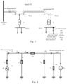
- Fig. 3 shows a schematic diagram of the connection of a power generation device and a substation according to an embodiment of the present disclosure.
- a substation 330 is shown, and a branch 300 is led out from a bus of the substation 330.
- a load and a power generation device can be connected on the branch 300.
- a transformer T1 is connected to the point of common coupling PCC1 on the branch 300, which is further connected with the point of common coupling PCC2 through the transformer T1, and the point of common coupling PCC2 can be connected with a load or power generation device.
- the power generation device 340 can be either a power generator or a renewable energy power generation device, e.g., a photovoltaic device (as shown in Fig. 3 ), a wind turbine, etc.
- the electrical line 350 from the substation 330 to the power generation device 340 remains connected, and the electrical line 350 is shown by a dotted line in Fig. 3 .
- the power generation device 340 will form an island power grid together with nearby loads, e.g., Under the condition that line disconnection occurs at the point of common coupling PCC3, the power generation device 340 and the load connected at the point of common coupling PCC4 form an island power grid, and only the power generation device 340 supply power to these loads.
- the first measuring unit 310 is arranged at the substation 330, and the second measuring unit 320 is arranged at the power generation device 340.
- Fig. 4 shows an equivalent circuit diagram of the connection of a power generation device and a substation according to an embodiment of the present disclosure.
- Substation 330 in Fig. 3 can be equivalent to the voltage source 401 with the voltage phasor ⁇ 1 and impedance ⁇ 1 on the left in Fig. 4 .
- the power generation device 430 in Fig. 3 can be equivalent to the current source with the current phasor ⁇ 2 and the admittance ⁇ 2 in Fig. 4 .
- the electrical line 350 between the power generation device 340 and the substation 330 can be equivalent to ⁇ shape equivalent circuit, which has the impedance ⁇ 12 and the admittance to the ground ⁇ L1 and ⁇ L2 .
- the voltage phasor at the substation is U ⁇ 1
- the current phasor at the substation is ⁇ 1
- the voltage phasor at the power generation device is U ⁇ 2 .
- the voltage drop caused by the current ⁇ 1 - ⁇ L1 U ⁇ 1 flowing through the impedance ⁇ 12 equals to the voltage difference U ⁇ 1 - U ⁇ 2 from the substation to the power generation device.
- the impedance ⁇ 12 between them is equal to the impedance ⁇ L of the electrical line 350is approximately equal to the sum of the impedances of all overhead lines, cables and transformers in the electrical line 350, and it has a very small value.
- the power generation device 340 cannot supply power to the nearby load self sufficiently, therefore the voltage frequency output by the power generation device 340 will change under the condition of power imbalance, and therefore the voltage phasor U ⁇ 2 will change continuously.
- the main power grid will produce power changes due to load changes.
- embodiments according to the present disclosure provide an apparatus for detecting the islanding state of a power generation device, which includes a first acquisition unit, a second acquisition unit and a processing unit.
- the first acquisition unit is for acquiring a first voltage phasor U ⁇ 1 and a first current phasor 1 at a substation 330.
- the second acquisition unit is for acquiring a second voltage phasor U ⁇ 2 at the power generation device 340.
- the processing unit is connected with the first acquisition unit and the second acquisition unit, and determines the interconnection impedance
- the interconnection impedance Z corr is equal to the impedance value of the electrical line 350, which has a very small value.
- the voltage phasor at the power generation device 340 changes, especially the frequency of the voltage phasor changes due to the unbalanced power of the island power grid.
- the current value at the substation 330 will also change.
- the predetermined interconnection threshold Z corr-set is set to be equal to or greater than the impedance value of the electrical line 350, i.e., the sum of the impedances of all overhead lines, cables and transformers in the electrical line 350.
- the predetermined interconnection threshold Z corr-set is, e.g., several tens of ohms, e.g. 10 ⁇ or 20 ⁇ .
- Fig. 5 shows a method 500 for detecting an islanding state of a power generation device according to an embodiment of the present disclosure.
- method 500 acquiring the first current amount at the substation (step 501), acquiring the second voltage phasor at the power generation device (step 502), and determining the interconnection impedance between the power generation device and the substation according to the ratio of the variation of the second voltage phasor and the variation of the first current amount within a same time period (step 503), and under the condition that the interconnection impedance meets a predetermined condition, (step 504), determining that the power generation device is in an islanding state (step 505).
- the predetermined condition may be to compare the interconnection impedance Z corr with a predetermined interconnection threshold Z corr-set , and under the condition that the interconnection impedance Z corr is greater than the predetermined interconnection threshold Z corr-set , i.e., Z corr > Z corr-set , the processing unit can determine that there is no electrical correlation between the power generation device and the substation.
- Fig. 6 shows a flowchart of a method 600 for detecting an islanding state of a power generation device according to another embodiment of the present disclosure.
- can be compared with a predetermined voltage change threshold U ⁇ set , i.e., and under the condition that the modulus of the variation of the second voltage phasor is greater than or equal to the predetermined voltage change threshold, i.e.,
- the processing unit determines the interconnection impedance, i.e., executes the method 500 shown in Fig. 5 (step 602).
- the frequency value of the second voltage phasor f 2 is compared with a predetermined upper frequency threshold f upper and a predetermined lower frequency threshold f lower , and under the condition that the frequency value of the second voltage phasor is greater than or less than the predetermined upper frequency threshold, i.e., f 2 > f upper or f 2 ⁇ f lower (step 603), it is determined that the power generation device is in an islanding state (step 604). Under the condition that the frequency offset of the second voltage phasor at the power generation device is too large, it can be directly determined that the power generation device is in an islanding state.
- can be compared with a predetermined upper voltage threshold U upper and a predetermined lower voltage threshold U lower , and under the condition that the modulus of the second voltage phasor is greater than or less than the predetermined upper voltage threshold, i.e.,
- is equal to 2 U 2 , where U 2 is the effective value of the second voltage.
- an additional voltage measuring unit may be provided to measure the effective value of the second voltage U 2 and compare it with a predetermined additional upper voltage threshold U upper ′ and an additional lower voltage threshold U lower ′ , and under the case that the effective value of the second voltage U 2 is greater than the predetermined additional upper voltage threshold or less than the predetermined additional lower voltage threshold, i.e., U 2 > U upper ′ or U 2 ⁇ U lower ′ , it is determined that the power generation device is in an islanding state. Under the condition that the modulus of the second voltage phasor
- step 603 and step 605 can be interchanged or can be executed in parallel.
- step 601, step 603 and step 605 By executing step 601, step 603 and step 605 in advance, the islanding state or non-islanding state with obvious features can be judged through simple steps, thereby can save the calculation amount and speeds up the speed of judging whether the power generation device is in the islanding state.
- the apparatus, methods and systems for detecting an islanding state of a power generation device it is determined whether the power generation device is separated from the main power grid by calculating the degree of electrical correlation between the power generation device and the substation, and therefore determined whether the power generation device is in the islanding state.
- the apparatus, method and system are realized based on a synchronous phasor measurement unit, and are different from the traditional active or passive islanding detection schemes, which have very high sensitivity compared with the traditional passive islanding detection schemes, i.e., have a very small detection blind area, and will not output disturbance to the power grid and therefore will not damage the power quality compared with the traditional active islanding detection schemes.
- circuits, units, means, apparatus, devices and systems involved in the present disclosure are only illustrative examples, and are not intended to require or imply that they must be connected, arranged and configured in the manner shown in the block diagram. As those skilled in the art will recognize, these circuits, units, means, apparatus, devices and systems can be connected, arranged and configured in any way, as long as the desired purpose can be achieved.
- the circuits, units, means and apparatus involved in the present disclosure can be implemented in any suitable way, e.g., by employing application specific-integrated circuits, field programmable gate arrays (FPGA), etc., or by employing general processing units combined with known programs.
- FPGA field programmable gate arrays
Landscapes
- Engineering & Computer Science (AREA)
- Power Engineering (AREA)
- Physics & Mathematics (AREA)
- General Physics & Mathematics (AREA)
- Supply And Distribution Of Alternating Current (AREA)
Abstract
Description
- The present disclosure relates to an apparatus for detecting an islanding state of a power generation device, a method for detecting an islanding state of a power generation device, and a system for detecting an islanding state of a power generation device.
- Islanding means that when a power supply interruption happens on a main power grid side, a power generation device fails to detect the disconnection from the main power grid in time and therefore does not stop operating, making the power generation device and its nearby loads form a self-sufficient island power grid. The island power grid cannot be controlled by the operator of the main power grid. In the islanding state, there may be a significant rated voltage offset and a rated frequency offset, which will lead to abnormal operation or damage to the electrical devices in the island power grid. Furthermore, when the power generation device in the island is reconnected to the grid, there may be inconsistent phase sequence, different sizes of amplitudes and different phases between the voltage of the main grid side and the voltage of the power generation device side, a differential voltage will be produced, and thus will cause a large surge current. This will damage the power quality and damage the electrical device and power generation device. For renewable energy power generation devices, e.g., photovoltaic devices and wind turbines, the islanding state will also affect the normal operation of the inverter in the power generation device. Under the condition that the power supply interruption of the power grid happens, the power generation device in the island makes the electrical device in the island still charged, which will cause misjudgment of the maintenance personnel and thus threaten personal safety. Therefore, when an islanding occurs, the occurrence of the islanding needs to be detected as soon as possible.
- The present disclosure provides an apparatus for detecting an islanding state of a power generation device, a method for detecting an islanding state of a power generation device and a system for detecting an islanding state of a power generation device. The apparatus, method and system for detecting the islanding state of a power generation device according to the present disclosure are capable of determining whether the power generation device is separated from the main power grid and therefore is in the islanding state under the condition that the power quality changes only slightly.
- An embodiment of the present disclosure provides an apparatus for detecting an islanding state of a power generation device, the apparatus includes: a first acquisition unit for acquiring a first current amount at a substation; a second acquisition unit for acquiring a second voltage phasor at the power generation device; a processing unit connected with the first acquisition unit and the second acquisition unit, for determining the interconnection impedance between the power generation device and the substation according to the ratio of the variation of the second voltage phasor and the variation of the first current within a same time period, and determining that the power generation device is in an islanding state under the condition that the interconnection impedance meets a predetermined condition.
- According to an embodiment of the present disclosure, a first current amount is a first current phasor.
- According to an embodiment of the present disclosure, before determining an interconnection impedance, a processing unit compares the modulus of the variation of a second voltage phasor with a predetermined voltage change threshold, and the processing unit determines the interconnection impedance under the condition that the modulus of the variation of the second voltage phasor is greater than or equal to the predetermined voltage change threshold.
- According to an embodiment of the present disclosure, before determining the interconnection impedance, the processing unit compares the modulus of the second voltage phasor with a predetermined upper voltage threshold and a predetermined lower voltage threshold, and determines that the power generation device is in an islanding state under the condition that the modulus of the second voltage phasor is greater than the predetermined upper voltage threshold or less than the predetermined lower voltage threshold.
- According to an embodiment of the present disclosure, before determining the interconnection impedance, the processing unit compares the frequency value of the second voltage phasor with a predetermined upper frequency threshold and a predetermined lower frequency threshold, and determines that the power generation device is in an islanding state under the condition that the frequency value of the second voltage phasor is greater than the predetermined upper frequency threshold or less than the predetermined lower frequency threshold.
- An embodiment of the present disclosure provides a method for detecting an islanding state of a power generation device, the method includes: acquiring a first current amount at a substation; acquiring a second voltage phasor at the power generation device; determining the interconnection impedance between the power generation device and the substation according to the ratio of the variation of the second voltage phasor and the variation of the first current within a same time period , and determining that the power generation device is in an islanding state under the condition that the interconnection impedance meets a predetermined condition.
- An embodiment of the present disclosure provides a system for detecting an islanding state of a power generation device, the system includes: the aforementioned device for detecting the islanding state of the power generation device; a first measuring unit arranged at a substation for measuring a first current amount at the substation; a second measuring unit arranged at the power generation device for measuring a second voltage phasor at the power generation device; wherein the apparatus is connected with the first measuring unit and the second measuring unit.
- According to an embodiment of the present disclosure, the second measuring unit is a synchronous phasor measurement unit.
- An embodiment of the present disclosure provides an apparatus for detecting an islanding state of a power generation device, the apparatus includes: a first acquisition unit for acquiring a first voltage phasor and a first current phasor at a substation; a second acquisition unit for acquiring a second voltage phasor at the power generation device; a processing unit connected with the first acquisition unit and the second acquisition unit, for determining an interconnection impedance between the power generation device and the substation within a predetermined time period, and determining that the power generation device is in an islanding state under the condition that the interconnection impedance is greater than a predetermined interconnection threshold, wherein the determination of the interconnection impedance between the power generation device and the substation includes the following calculation:

- The apparatus, method and system for detecting the islanding state of a power generation device according to the present disclosure determines whether the power generation device is separated from the main power grid by calculating the degree of electrical correlation between the power generation device and the substation, and therefore determines whether the power generation device is in an islanding state. The apparatus, method and system are realized based on a synchronous phasor measurement unit, and are different from the traditional active or passive islanding detection schemes, which have very high sensitivity compared with the traditional passive islanding detection schemes, i.e., have a very small detection blind area, and will not output disturbance to the power grid and therefore will not damage the power quality compared with the traditional active islanding detection schemes.
- In order to explain the technical scheme of the embodiment of the present disclosure more clearly, the drawings required for use in the description of the embodiment will be briefly introduced below. The drawings in the following description are only exemplary embodiments of the present disclosure.
-
Fig. 1 shows a schematic block diagram of an apparatus for detecting an islanding state of a power generation device according to an embodiment of the present disclosure, -
Fig. 2 shows a schematic diagram of a system for detecting an islanding state of a power generation device according to an embodiment of the present disclosure, -
Fig. 3 shows a schematic diagram of the connection of a power generation device and a substation according to an embodiment of the present disclosure, -
Fig. 4 shows an equivalent circuit diagram of the connection of a power generation device and a substation according to an embodiment of the present disclosure, -
Fig. 5 shows a flowchart of a method for detecting an islanding state of a power generation device according to an embodiment of the present disclosure, -
Fig. 6 shows a flowchart of a method for detecting an islanding state of a power generation device according to another embodiment of the present disclosure. - In order to make the purposes, technical schemes and advantages of the present disclosure more obvious, example embodiments according to the present disclosure will be described in detail below with reference to the accompanying drawings. Obviously, the described embodiments are only a part of the embodiments of the present disclosure, not all the embodiments of the present disclosure, and it should be understood that the present disclosure is not limited by the example embodiments described herein.
- In the present specification and the drawings, basically the same or similar steps and elements are denoted by the same or similar reference numerals, and repeated descriptions of these steps and elements will be omitted. Meanwhile, in the description of the present disclosure, the terms "first", "second" and so on are only used to distinguish descriptions, and cannot be understood as indicating or implying relative importance or ranking.
- In the present specification and drawings, according to embodiments, elements are described in singular or plural forms. However, the singular and plural forms are appropriately selected for the proposed situation only for convenience of explanation and are not intended to limit the present disclosure. Therefore, the singular form can include the plural form, and the plural form can also include the singular form unless the context clearly states otherwise. In the embodiments of the present disclosure, unless clearly stated otherwise, "connection" does not mean that it must "direct connection" or "direct touch", while only electrical and/or communication connection is required.
-
Fig. 1 shows a schematic block diagram of an apparatus 100 for detecting an islanding state of a power generation device according to an embodiment of the present disclosure. The device for detecting the islanding state of the power generation device includes afirst acquisition unit 101, asecond acquisition unit 102 and aprocessing unit 103. Thefirst acquisition unit 101 is for acquiring a first current amount at a substation. Thesecond acquisition unit 102 is for acquiring a second voltage phasor at the power generation device. Theprocessing unit 103 is connected with thefirst acquisition unit 101 and thesecond acquisition unit 102, and is used for determining the interconnection impedance Z corr between the power generation device and the substation according to the ratio of the variation of the second voltage phasor and the variation of the first current within a same time period, and determining that the power generation device is in an islanding state under the condition that the interconnection impedance Z corr meets a predetermined condition. - According to an embodiment of the present disclosure, the first current obtained at a substation may be, e.g., a vector İ 1, e.g., a current phasor measured by a synchronous phasor measurement unit, or a scalar I 1, e.g., an effective value of a current measured by a current transformer. The variation of the vector of the first current corresponds to the variation of the scalar of the first current, because the frequency of the current of the main power grid on the substation side will not change regardless of whether the islanding occurs or not, therefore


- According to an embodiment of the present disclosure, the predetermined condition may be to compare the interconnection impedance Z corr with a predetermined interconnection threshold Zcorr-set. Under the condition that the interconnection impedance Z corr is greater than the predetermined interconnection threshold Zcorr-set, that is

- According to an embodiment of the present disclosure, before determining the interconnection impedance Zcorr, the
processing unit 103 compares the modulus of the variation of the second voltage phasor |ΔU̇ 2| with a predetermined voltage change threshold UΔset , and theprocessing unit 103 determines the interconnection impedance Z corr under the condition that the modulus of the variation of the second voltage phasor |ΔU̇ 2| is greater than or equal to the predetermined voltage change threshold UΔset . That is, theprocessing unit 103 calculates the interconnection impedance Z corr according to equation (1) only under the condition that |ΔU̇ 2| ≥ UΔset . -
Fig. 2 shows a schematic diagram of a system for detecting an islanding state of a power generation device according to an embodiment of the present disclosure, which includes the apparatus 100 for detecting the islanding state of the power generation device as shown inFig. 1 , afirst measuring unit 201 and a second measuring unit 202. Thefirst measuring unit 201 is arranged at asubstation 210 for measuring a first current amount at thesubstation 210. The second measuring unit 202 is arranged at apower generation device 220 for measuring a second voltage phasor at thepower generation device 220. The apparatus 100 is connected with thefirst measuring unit 201 and thesecond measuring unit 220. The apparatus 100 for detecting the islanding state of a power generation device, e.g., can be connected with thefirst measuring unit 201 and thesecond measuring unit 220 in a wired or wireless way, thus thefirst measuring unit 201 can send the first current amount at thesubstation 210 to the apparatus 100, and the second measuring unit 202 can send the second voltage phasor at thepower generation device 220 to the device 100. The apparatus 100 can calculate the interconnection impedance Z corr between thepower generation device 220 and thesubstation 210 as described in detail above, and determine whether thepower generation device 220 is disconnected from thesubstation 210 and therefore is in an islanding state. - According to an embodiment of the present disclosure, the second measuring unit 202 is, e.g., a synchronous phasor measurement unit (PMU), and particularly can be a micro synchronous phasor measurement unit (µPMU). The synchronous phasor measurement unit is a phasor measuring unit composed of the Global Positioning System (GPS) second pulse as the synchronous clock. The second measuring unit 202 measures the second voltage phasor at the
power generation device 220 as a PMU and sends it to the apparatus 100. - According to an embodiment of the present disclosure, the
first measuring unit 201, e.g., may also be a PMU. In this case, thefirst measuring unit 201 measures the first current phasor at thesubstation 210 and sends it to the apparatus 100, and the first current phasor and the second voltage phasor are sent to the device 100 synchronously in time. In addition, thefirst measuring unit 201 may be, e.g., a measuring device for measuring the effective value of the current, e.g. a current transformer. Thefirst measuring unit 201 sends a first current amount as a scalar to the apparatus 100. In this case, it is also necessary to guarantee that the first current amount as a scalar is synchronized with the second voltage phasor in time. -
Fig. 3 shows a schematic diagram of the connection of a power generation device and a substation according to an embodiment of the present disclosure. InFig. 3 , asubstation 330 is shown, and abranch 300 is led out from a bus of thesubstation 330. A load and a power generation device can be connected on thebranch 300. In the exemplary diagram shown inFig. 3 , a transformer T1 is connected to the point of common coupling PCC1 on thebranch 300, which is further connected with the point of common coupling PCC2 through the transformer T1, and the point of common coupling PCC2 can be connected with a load or power generation device. Similarly, another point of common coupling PCC3 on thebranch 300 is connected with a transformer T2, which is further connected with the point of common coupling PCC4, the point of common coupling PCC4 can be connected with a load or a power generation device, and the power generation device 340 is shown here. The power generation device 340 can be either a power generator or a renewable energy power generation device, e.g., a photovoltaic device (as shown inFig. 3 ), a wind turbine, etc. - Under the normal operation of the
branch 300, theelectrical line 350 from thesubstation 330 to the power generation device 340 remains connected, and theelectrical line 350 is shown by a dotted line inFig. 3 . Under the condition that any point in theelectrical line 350 is disconnected, the power generation device 340 will form an island power grid together with nearby loads, e.g., Under the condition that line disconnection occurs at the point of common coupling PCC3, the power generation device 340 and the load connected at the point of common coupling PCC4 form an island power grid, and only the power generation device 340 supply power to these loads. In order to detect the island power grid that might be composed of the power generation device 340, i.e., to detect whether theelectrical line 350 is disconnected, thefirst measuring unit 310 is arranged at thesubstation 330, and thesecond measuring unit 320 is arranged at the power generation device 340. -
Fig. 4 shows an equivalent circuit diagram of the connection of a power generation device and a substation according to an embodiment of the present disclosure.Substation 330 inFig. 3 can be equivalent to thevoltage source 401 with the voltage phasor Ė 1 and impedance Ż1 on the left inFig. 4 . The power generation device 430 inFig. 3 can be equivalent to the current source with the current phasor İ 2 and the admittance Ẏ2 inFig. 4 . Theelectrical line 350 between the power generation device 340 and thesubstation 330 can be equivalent to π shape equivalent circuit, which has the impedance Ż 12 and the admittance to the ground ẎL1 and ẎL2. - The voltage phasor at the substation is U̇ 1, the current phasor at the substation is İ 1, and the voltage phasor at the power generation device is U̇ 2. According to the voltage drop on the impedance Ż 12, the following equation can be established:

- That is, the voltage drop caused by the current İ 1 - ẎL1 U̇ 1 flowing through the impedance Ż 12 equals to the voltage difference U̇ 1 - U̇ 2 from the substation to the power generation device.
- It is assumed that the output power of the power generation device 340 is changed, which causes the voltage phasor U̇ 1 at the substation, the current phasor İ 1 and the voltage phasor at U̇ 2 at the power generation device to change as follows within a time period ΔT:


- Under the condition that the
electrical line 350 between thesubstation 330 and the power generation device 340 remains connected, the impedance Ż 12 between them is equal to the impedance Ż L of the electrical line 350is approximately equal to the sum of the impedances of all overhead lines, cables and transformers in theelectrical line 350, and it has a very small value. - However, under the condition that any position on the
electrical line 350 is disconnected, i.e., under the condition that the power generation device 340 forms an island power grid, the power generation device 340 cannot supply power to the nearby load self sufficiently, therefore the voltage frequency output by the power generation device 340 will change under the condition of power imbalance, and therefore the voltage phasor U̇ 2 will change continuously. In addition, on the substation side, the main power grid will produce power changes due to load changes. These above-mentioned changes will lead to the impedance value, i.e., the modulus of the impedance |Ż 12| between thesubstation 330 and the power generation device 340 becomes larger, and it is much larger than the impedance Ż L of theelectrical line 350 - In order to calculate the modulus of impedance |Ż 12| according to equation (6), embodiments according to the present disclosure provide an apparatus for detecting the islanding state of a power generation device, which includes a first acquisition unit, a second acquisition unit and a processing unit. The first acquisition unit is for acquiring a first voltage phasor U̇ 1 and a first current phasor 1 at a
substation 330. The second acquisition unit is for acquiring a second voltage phasor U̇ 2 at the power generation device 340. The processing unit is connected with the first acquisition unit and the second acquisition unit, and determines the interconnection impedance |Ż corr| = |Ż 12| between the power generation device 340 and thesubstation 330 through equation (6), i.e., first, calculate the variation ΔU̇ 1 of the first voltage phasor multiplied by the second voltage phasor U̇ 2 minus the variation ΔU̇ 2 of the second voltage phasor multiplied by the first voltage phasor U̇ 1; then calculate the variation Δİ 1 of the first current phasor multiplied by the first voltage phasor U̇ 1 minus the variation ΔU̇ 1 of the first voltage phasor multiplied by the first current phasor İ 1; finally, calculate the modulus of their ratio:
- After the power generation device 340 is disconnected from the
substation 330, although power changes will occur at both the power generation device side and the substation side, the voltage phasor changes at the substation side are very small and almost negligible. Therefore, it can be assumed that:
- Therefore, equation (7) can be simplified as:


- Under the condition that the power generation device 340 and the
substation 330 remain electrical correlations, the interconnection impedance Z corr is equal to the impedance value of theelectrical line 350, which has a very small value. However, under the condition that the power generation device 340 loses electrical correlation with thesubstation 330, the voltage phasor at the power generation device 340 changes, especially the frequency of the voltage phasor changes due to the unbalanced power of the island power grid. In addition, due to the loss of load, the current value at thesubstation 330 will also change. These changes cause the interconnection impedance Z corr to become larger and much larger than the impedance value of theelectrical line 350. - According to an embodiment of the present disclosure, e.g., the predetermined interconnection threshold Zcorr-set is set to be equal to or greater than the impedance value of the
electrical line 350, i.e., the sum of the impedances of all overhead lines, cables and transformers in theelectrical line 350. Preferably, the predetermined interconnection threshold Zcorr-set is, e.g., several tens of ohms, e.g. 10 Ω or 20 Ω. -
Fig. 5 shows amethod 500 for detecting an islanding state of a power generation device according to an embodiment of the present disclosure. Inmethod 500, acquiring the first current amount at the substation (step 501), acquiring the second voltage phasor at the power generation device (step 502), and determining the interconnection impedance between the power generation device and the substation according to the ratio of the variation of the second voltage phasor and the variation of the first current amount within a same time period (step 503), and under the condition that the interconnection impedance meets a predetermined condition, (step 504), determining that the power generation device is in an islanding state (step 505). According to an embodiment of the present disclosure, the predetermined condition may be to compare the interconnection impedance Z corr with a predetermined interconnection threshold Zcorr-set, and under the condition that the interconnection impedance Z corr is greater than the predetermined interconnection threshold Zcorr-set, i.e., Z corr > Zcorr-set, the processing unit can determine that there is no electrical correlation between the power generation device and the substation. -
Fig. 6 shows a flowchart of a method 600 for detecting an islanding state of a power generation device according to another embodiment of the present disclosure. According to the embodiment of the present disclosure, before executing themethod 500, the modulus of the variation of the second voltage phasor |ΔU̇ 2| can be compared with a predetermined voltage change threshold UΔset , i.e., and under the condition that the modulus of the variation of the second voltage phasor is greater than or equal to the predetermined voltage change threshold, i.e., |ΔU̇ 2| ≥ UΔset (step 601), the processing unit determines the interconnection impedance, i.e., executes themethod 500 shown inFig. 5 (step 602). - According to an embodiment of the present disclosure, before executing
step 601, the frequency value of the second voltage phasor f 2 is compared with a predetermined upper frequency threshold fupper and a predetermined lower frequency threshold flower, and under the condition that the frequency value of the second voltage phasor is greater than or less than the predetermined upper frequency threshold, i.e., f 2 > f upper or f 2 < flower (step 603), it is determined that the power generation device is in an islanding state (step 604). Under the condition that the frequency offset of the second voltage phasor at the power generation device is too large, it can be directly determined that the power generation device is in an islanding state. - According to an embodiment of the present disclosure, before executing
step 601, the modulus of the second voltage phasor |U̇ 2| can be compared with a predetermined upper voltage threshold Uupper and a predetermined lower voltage threshold Ulower, and under the condition that the modulus of the second voltage phasor is greater than or less than the predetermined upper voltage threshold, i.e., |U̇ 2| > Uupper or |U̇ 2| < Ulower (step 605), it is determined that the power generation device is in an islanding state (step 606). The modulus of the second voltage phasor |U̇ 2| is equal to


- According to the embodiment of the present disclosure, the execution order of
step 603 and step 605 can be interchanged or can be executed in parallel. - By executing
step 601,step 603 and step 605 in advance, the islanding state or non-islanding state with obvious features can be judged through simple steps, thereby can save the calculation amount and speeds up the speed of judging whether the power generation device is in the islanding state. - According to the apparatus, methods and systems for detecting an islanding state of a power generation device, it is determined whether the power generation device is separated from the main power grid by calculating the degree of electrical correlation between the power generation device and the substation, and therefore determined whether the power generation device is in the islanding state. The apparatus, method and system are realized based on a synchronous phasor measurement unit, and are different from the traditional active or passive islanding detection schemes, which have very high sensitivity compared with the traditional passive islanding detection schemes, i.e., have a very small detection blind area, and will not output disturbance to the power grid and therefore will not damage the power quality compared with the traditional active islanding detection schemes.
- The block diagrams of circuits, units, means, apparatus, devices and systems involved in the present disclosure are only illustrative examples, and are not intended to require or imply that they must be connected, arranged and configured in the manner shown in the block diagram. As those skilled in the art will recognize, these circuits, units, means, apparatus, devices and systems can be connected, arranged and configured in any way, as long as the desired purpose can be achieved. The circuits, units, means and apparatus involved in the present disclosure can be implemented in any suitable way, e.g., by employing application specific-integrated circuits, field programmable gate arrays (FPGA), etc., or by employing general processing units combined with known programs.
- It should be understood by those skilled in the art that the above-mentioned specific embodiments are only examples rather than limitations, and various modifications, combinations, partial combinations and substitutions can be made to the embodiments of the present disclosure according to design requirements and other factors, as long as they are within the scope of the appended claims or their equivalents, i.e., they belong to the scope of rights to be protected by the present disclosure.
Claims (9)
- An apparatus for detecting an islanding state of a power generation device, comprising:a first acquisition unit for acquiring a first current amount at a substation;a second acquisition unit for acquiring a second voltage phasor at the power generation device;a processing unit connected with the first acquisition unit and the second acquisition unit, for determining an interconnection impedance between the power generation device and the substation according to a ratio of a variation of the second voltage phasor and a variation of the first current amount within a same time period, and determining that the power generation device is in an islanding state under the condition that the interconnection impedance meets a predetermined condition.
- The apparatus according to claim 1, wherein the first current amount is a first current phasor.
- The apparatus according to claim 1, wherein before determining the interconnection impedance, the processing unit compares a modulus of the variation of the second voltage phasor with a predetermined voltage change threshold, and the processing unit determines the interconnection impedance under the condition that a modulus of the variation of the second voltage phasor is greater than or equal to a predetermined voltage change threshold.
- The apparatus according to claim 1, wherein before determining the interconnection impedance, the processing unit compares a modulus of the second voltage phasor with a predetermined upper voltage threshold and a predetermined lower voltage threshold, and determines that the power generation device is in an islanding state under the condition that a modulus of the second voltage phasor is greater than a predetermined upper voltage threshold or less than a predetermined lower voltage threshold.
- The apparatus according to claim 1, wherein before determining the interconnection impedance, the processing unit compares a frequency value of the second voltage phasor with a predetermined upper frequency threshold and a predetermined lower frequency threshold, and determines that the power generation device is in an islanding state under the condition that a frequency value of the second voltage phasor is greater than a predetermined upper frequency threshold or less than a predetermined lower frequency threshold.
- A method for detecting an islanding state of a power generation device, comprising:acquiring a first current amount at a substation;acquiring a second voltage phasor at the power generation device;determining an interconnection impedance between the power generation device and the substation according to a ratio of a variation of the second voltage phasor and a variation of the first current within a same time period, and;determining that the power generation device is in an islanding state under the condition that the interconnection impedance meets a predetermined condition.
- A system for detecting an islanding state of a power generation device, comprising:the apparatus according to any one of claims 1 to 5;a first measuring unit arranged at a substation for measuring a first current amount at the substation;a second measuring unit arranged at the power generation device for measuring a second voltage phasor at the power generation device;wherein the apparatus is connected with the first measuring unit and the second measuring unit.
- The system according to claim 7, wherein the second measuring unit is a synchronous phasor measurement unit.
- An apparatus for detecting an islanding state of a power generation device, comprising:a first acquisition unit for acquiring a first voltage phasor and a first current phasor at a substation;a second acquisition unit for acquiring a second voltage phasor at the power generation device;a processing unit connected with the first acquisition unit and the second acquisition unit, for determining an interconnection impedance between the power generation device and the substation within a predetermined time period, anddetermining that the power generation device is in an islanding state under the condition that the interconnection impedance is greater than a predetermined interconnection threshold, whereinthe determination of an interconnection impedance between the power generation device and the substation includes the following calculation:

Applications Claiming Priority (1)
| Application Number | Priority Date | Filing Date | Title |
|---|---|---|---|
| CN202211467695.5A CN118068123A (en) | 2022-11-22 | 2022-11-22 | Device, method and system for detecting islanding state of power generation equipment |
Publications (2)
| Publication Number | Publication Date |
|---|---|
| EP4383506A2 true EP4383506A2 (en) | 2024-06-12 |
| EP4383506A3 EP4383506A3 (en) | 2024-07-17 |
Family
ID=89119519
Family Applications (1)
| Application Number | Title | Priority Date | Filing Date |
|---|---|---|---|
| EP23307015.0A Pending EP4383506A3 (en) | 2022-11-22 | 2023-11-21 | Apparatus, method and system for detecting an islanding state of a power generation device |
Country Status (3)
| Country | Link |
|---|---|
| US (1) | US20240168102A1 (en) |
| EP (1) | EP4383506A3 (en) |
| CN (1) | CN118068123A (en) |
Family Cites Families (8)
| Publication number | Priority date | Publication date | Assignee | Title |
|---|---|---|---|---|
| EP2501014B1 (en) * | 2011-03-14 | 2016-05-11 | ABB Research Ltd. | Method and apparatus for detecting islanding conditions of distributed generator |
| US9608440B2 (en) * | 2011-11-08 | 2017-03-28 | Eaton Corporation | Methods and apparatus for determining power distribution system topology using disturbance detection |
| CN104598660B (en) * | 2013-10-31 | 2017-11-17 | 国际商业机器公司 | The method and system of island effect is detected in electric power networks topology |
| US9806513B2 (en) * | 2015-02-26 | 2017-10-31 | Raytheon Company | Robust solid-state circuit protection apparatus |
| US11309702B2 (en) * | 2018-02-27 | 2022-04-19 | Hitachi Energy Switzerland Ag | Systems and methods for islanding protection |
| US11211792B2 (en) * | 2018-07-06 | 2021-12-28 | Schneider Electric USA, Inc. | Supplemental techniques for characterizing power quality events in an electrical system |
| WO2022072570A1 (en) * | 2020-10-01 | 2022-04-07 | S&C Electric Company | Radial restoration |
| FI20225309A1 (en) * | 2022-04-08 | 2023-10-09 | Safegrid Oy | Method and system for management of electric grid |
-
2022
- 2022-11-22 CN CN202211467695.5A patent/CN118068123A/en active Pending
-
2023
- 2023-11-21 EP EP23307015.0A patent/EP4383506A3/en active Pending
- 2023-11-21 US US18/516,441 patent/US20240168102A1/en active Pending
Also Published As
| Publication number | Publication date |
|---|---|
| US20240168102A1 (en) | 2024-05-23 |
| EP4383506A3 (en) | 2024-07-17 |
| CN118068123A (en) | 2024-05-24 |
Similar Documents
| Publication | Publication Date | Title |
|---|---|---|
| RU2576340C2 (en) | Method and device for ground fault detection based on change in three-phase current | |
| Marchesan et al. | Passive method for distributed-generation island detection based on oscillation frequency | |
| Best et al. | Synchronous islanded operation of a diesel generator | |
| CN103296643B (en) | Comparative isolated island detection and protection method based on wide range information phase difference | |
| CN103438797B (en) | Deformation of transformer winding online test method and system | |
| CN105811383A (en) | Novel positive sequence impedance differential protection method of microgrid | |
| CN103983873B (en) | Island detection method suitable for multi-inverter parallel operation and based on impedance measurement | |
| US10073148B2 (en) | Fault detection in energy supply networks | |
| CN105182189B (en) | The inverter combined based on electric voltage frequency and measurement impedance disturbs formula isolated island detection method | |
| CN109490638A (en) | The impedance measurement formula isolated island detection method of the grid-connected direct current power system of more photo-voltaic power supplies | |
| CN103412207A (en) | Photovoltaic grid connected inverter island detection method based on negative sequence current injection | |
| CN108919054A (en) | The intelligent power distribution network short circuit fault localization method estimated based on load and branch line | |
| CN103293443A (en) | Overhead wire grounding fault locating method for power distribution network | |
| CN109066610B (en) | Island power grid line fault positioning method | |
| US20180026446A1 (en) | Seamless transition between grid connected and islanded modes | |
| CN106684834A (en) | Adaptive current protection system and method for power distribution network | |
| EP2806280A1 (en) | Detecting electrical islands using wide-area measurements | |
| CN107104420B (en) | I segment protection method of route distance suitable for THE UPFC access | |
| CN104865479A (en) | Islanding detecting method | |
| Sharma et al. | Transient power polarity based fault detection in DC microgrid with localized backup scheme | |
| CN115184737A (en) | Detection method for cable and overhead mixed transmission and distribution line | |
| CN102565598A (en) | Island detection method based on negative sequence voltage divider | |
| Esmaeilian et al. | Evaluation and performance comparison of power swing detection algorithms in presence of series compensation on transmission lines | |
| CN104242350A (en) | Miniature grid-connected inverter anti-islanding method based on group control disturbance | |
| EP4383506A2 (en) | Apparatus, method and system for detecting an islanding state of a power generation device |
Legal Events
| Date | Code | Title | Description |
|---|---|---|---|
| PUAI | Public reference made under article 153(3) epc to a published international application that has entered the european phase |
Free format text: ORIGINAL CODE: 0009012 |
|
| STAA | Information on the status of an ep patent application or granted ep patent |
Free format text: STATUS: THE APPLICATION HAS BEEN PUBLISHED |
|
| AK | Designated contracting states |
Kind code of ref document: A2 Designated state(s): AL AT BE BG CH CY CZ DE DK EE ES FI FR GB GR HR HU IE IS IT LI LT LU LV MC ME MK MT NL NO PL PT RO RS SE SI SK SM TR |
|
| PUAL | Search report despatched |
Free format text: ORIGINAL CODE: 0009013 |
|
| AK | Designated contracting states |
Kind code of ref document: A3 Designated state(s): AL AT BE BG CH CY CZ DE DK EE ES FI FR GB GR HR HU IE IS IT LI LT LU LV MC ME MK MT NL NO PL PT RO RS SE SI SK SM TR |
|
| RIC1 | Information provided on ipc code assigned before grant |
Ipc: H02J 13/00 20060101ALI20240610BHEP Ipc: H02J 3/00 20060101ALI20240610BHEP Ipc: H02J 3/38 20060101AFI20240610BHEP |
|
| STAA | Information on the status of an ep patent application or granted ep patent |
Free format text: STATUS: REQUEST FOR EXAMINATION WAS MADE |
|
| 17P | Request for examination filed |
Effective date: 20241219 |