EP4383489A1 - Flexible grommet assembly - Google Patents
Flexible grommet assembly Download PDFInfo
- Publication number
- EP4383489A1 EP4383489A1 EP23201790.5A EP23201790A EP4383489A1 EP 4383489 A1 EP4383489 A1 EP 4383489A1 EP 23201790 A EP23201790 A EP 23201790A EP 4383489 A1 EP4383489 A1 EP 4383489A1
- Authority
- EP
- European Patent Office
- Prior art keywords
- grommet
- panel
- grommet body
- flexible
- opening
- Prior art date
- Legal status (The legal status is an assumption and is not a legal conclusion. Google has not performed a legal analysis and makes no representation as to the accuracy of the status listed.)
- Pending
Links
- 238000000034 method Methods 0.000 claims description 21
- 230000008878 coupling Effects 0.000 claims description 6
- 238000010168 coupling process Methods 0.000 claims description 6
- 238000005859 coupling reaction Methods 0.000 claims description 6
- 239000011343 solid material Substances 0.000 claims description 4
- 238000005452 bending Methods 0.000 claims description 3
- 230000013011 mating Effects 0.000 description 13
- 239000000463 material Substances 0.000 description 6
- 238000004519 manufacturing process Methods 0.000 description 5
- 239000000654 additive Substances 0.000 description 2
- 230000000996 additive effect Effects 0.000 description 2
- 238000004026 adhesive bonding Methods 0.000 description 2
- 238000005520 cutting process Methods 0.000 description 2
- 239000003292 glue Substances 0.000 description 2
- 238000011900 installation process Methods 0.000 description 2
- 239000000853 adhesive Substances 0.000 description 1
- 230000001070 adhesive effect Effects 0.000 description 1
- 230000000295 complement effect Effects 0.000 description 1
- 239000002131 composite material Substances 0.000 description 1
- 238000010276 construction Methods 0.000 description 1
- 238000005530 etching Methods 0.000 description 1
- 238000000605 extraction Methods 0.000 description 1
- 238000001746 injection moulding Methods 0.000 description 1
- 238000009434 installation Methods 0.000 description 1
- 239000007769 metal material Substances 0.000 description 1
- 238000012986 modification Methods 0.000 description 1
- 230000004048 modification Effects 0.000 description 1
- 238000000465 moulding Methods 0.000 description 1
- 239000007787 solid Substances 0.000 description 1
Images




Classifications
-
- H—ELECTRICITY
- H01—ELECTRIC ELEMENTS
- H01B—CABLES; CONDUCTORS; INSULATORS; SELECTION OF MATERIALS FOR THEIR CONDUCTIVE, INSULATING OR DIELECTRIC PROPERTIES
- H01B17/00—Insulators or insulating bodies characterised by their form
- H01B17/56—Insulating bodies
- H01B17/58—Tubes, sleeves, beads, or bobbins through which the conductor passes
- H01B17/583—Grommets; Bushings
-
- H—ELECTRICITY
- H02—GENERATION; CONVERSION OR DISTRIBUTION OF ELECTRIC POWER
- H02G—INSTALLATION OF ELECTRIC CABLES OR LINES, OR OF COMBINED OPTICAL AND ELECTRIC CABLES OR LINES
- H02G3/00—Installations of electric cables or lines or protective tubing therefor in or on buildings, equivalent structures or vehicles
- H02G3/02—Details
- H02G3/04—Protective tubing or conduits, e.g. cable ladders or cable troughs
- H02G3/0406—Details thereof
-
- H—ELECTRICITY
- H02—GENERATION; CONVERSION OR DISTRIBUTION OF ELECTRIC POWER
- H02G—INSTALLATION OF ELECTRIC CABLES OR LINES, OR OF COMBINED OPTICAL AND ELECTRIC CABLES OR LINES
- H02G15/00—Cable fittings
-
- H—ELECTRICITY
- H02—GENERATION; CONVERSION OR DISTRIBUTION OF ELECTRIC POWER
- H02G—INSTALLATION OF ELECTRIC CABLES OR LINES, OR OF COMBINED OPTICAL AND ELECTRIC CABLES OR LINES
- H02G3/00—Installations of electric cables or lines or protective tubing therefor in or on buildings, equivalent structures or vehicles
- H02G3/22—Installations of cables or lines through walls, floors or ceilings, e.g. into buildings
Definitions
- the present disclosure generally relates to grommets that couple to panels and surround one or more objects that extend through the panels.
- Grommets are installed on panels at openings in the panel to protect an interface between a panel edge of the opening and the one or more objects that are routed through the opening. Typically, grommets are used to protect wires and wire harnesses from damage due to rubbing along the rough texture of the panel edge. Some industries and applications may require the use of grommets when routing electrical wires through panels.
- Known snap grommets which include two parts that snap together to sandwich the panel, are designed for planar panels, and may not function well if the panel is curved. For example, the two parts of known snap grommets may not be able to couple together on a curved panel due to the latching features not properly aligning.
- the snap grommet would not conform to the curved contour, which would frustrate the purpose of the snap grommet. For example, along a concave surface, the snap grommet may separate from the panel edge, which could allow the wires to rub against the rough panel edge.
- a conventional process of installing grommets on curved panels is to glue the grommet in place, rather than use a snap grommet. For example, a mechanic may measure and cut a grommet to size, and then glue the grommet to the curved panel. This process is time-consuming, considering the assembly time and cure time. The use of adhesive can also be messy, requiring an additional clean-up step.
- a flexible grommet assembly that includes a first grommet body and a second grommet body.
- the first grommet body includes first articulated segments that define a first hinge region.
- the second grommet body includes second articulated segments that define a second hinge region.
- the first and second grommet bodies are configured to cooperatively couple to an opening of a panel such that the first and second grommet bodies are flexed about their respective first and second hinge regions to conform to a curvature in the panel.
- Certain examples of the present disclosure provide an aircraft that includes an interior cabin and a flexible grommet assembly.
- the interior cabin includes a curved panel that defines an opening therethrough.
- the flexible grommet assembly is installed on the curved panel.
- the flexible grommet assembly includes a first grommet body and a second grommet body.
- the first grommet body includes first articulated segments that define a first hinge region
- the second grommet body includes second articulated segments that define a second hinge region.
- the first and second grommet bodies are configured to cooperatively couple to the opening of the curved panel such that the first and second grommet bodies are flexed about their respective first and second hinge regions to conform to a curvature in the curved panel.
- Certain examples of the present disclosure provide a method of installing a flexible grommet assembly on a panel.
- the method includes positioning a first grommet body along a first side of a panel at an opening that extends through the panel, and positioning a second grommet body along a second side of the panel at the opening. The second side is opposite the first side.
- the first grommet body includes first articulated segments that define a first hinge region.
- the second grommet body includes second articulated segments that define a second hinge region.
- the method includes coupling the first and second grommet bodies together through the opening such that the first and second grommet bodies are flexed about their respective first and second hinge regions to conform to a curvature in the panel.
- the flexible grommet assembly includes integrated flexible hinges within the respective bodies of first and second grommets of the flexible grommet assembly.
- the hinges enable the flexible grommet assembly to be installed on flat panels as well as curved panels (e.g., concave or convex), without customizing the grommet assembly.
- the flexible hinges upon snapping the grommet assembly onto a curved panel, the flexible hinges enable the first and second grommet bodies to follow the contour of the panel and remain in contact with an edge of a panel opening.
- the flexible grommet assembly is designed to be quickly installed by snapping the first and second grommet bodies together from opposite sides of the panel.
- the flexible grommet assembly can avoid drawbacks associated with installing custom grommets on curved panels, including the effort, cost, safety risk, and/or clean-up attributable to measuring, cutting, and gluing the grommet into place.
- the installation of the flexible grommet assembly, according to the examples herein, on a curved panel may be substantially quicker, easier, cheaper, cleaner, and/or safer than the known process that involves cutting and gluing.
- a curved panel as described herein refers to a non-planar section of a panel that surrounds and defines an opening or pass-through window for receiving wires and/or other objects therethrough.
- FIG 1 is an isometric view of a flexible grommet assembly 100 according to an example.
- the flexible grommet assembly 100 includes a first grommet body 102 and the second grommet body 104.
- the first and second grommet bodies 102, 104 are discrete, separate components that are designed with complementary features to cooperatively couple to each other and attach to an opening of a panel.
- Figure 1 shows the grommet bodies 102, 104 in the coupled state.
- the grommet bodies 102, 104 are designed to couple to each other through the panel opening.
- Figure 2 is a plan view of the flexible grommet assembly 100 installed on a panel 110.
- the panel 110 is shown in cross-section in Figure 2 to avoid obstructing the view of the flexible grommet assembly 100.
- the panel 110 has a first side 112 and a second side 114 opposite the first side 112.
- the panel 110 may have a one-piece construction or may be a composite.
- the panel 110 includes an edge 116 that defines an opening 118.
- the opening 118 extends through a thickness of the panel 110 from the first side 112 to the second side 114.
- the section of the panel 110 shown in Figure 2 is planar.
- the flexible grommet assembly 100 is designed to flex and bend, if necessary, to conform to curved panel sections.
- the first and second grommet bodies 102, 104 When installed on the panel 110, the first and second grommet bodies 102, 104 are in the coupled state as shown in Figure 1 and sandwich the panel 110. Portions of the grommet bodies 102, 104 extend through the opening 118 to engage and secure to the respective opposing grommet body 102, 104.
- the following description refers to both Figures 1 and 2 .
- the first grommet body 102 includes first latch features 120 and defines a first passageway 122 (e.g., grommet opening).
- the first passageway 122 aligns with the opening 118 of the panel 110 when installed and receives wires and/or other objects therethrough.
- the first grommet body 102 is box-shaped, and the first passageway 122 is framed by the box-shaped first grommet body 102.
- the first passageway 122 is obstructed from view in Figure 2 by an upper segment of the first grommet body 102.
- the first latch features 120 are designed to extend through the opening 118 of the panel 110 and couple to the second grommet body 104 to secure the flexible grommet assembly 100 onto the panel 110.
- the first latch features 120 may prohibit the first and second grommet bodies 102, 104 from being pulled away from each other, which secures both grommet bodies 102, 104 to the panel 110 sandwiched therebetween.
- the first grommet body 102 includes first articulated segments 124 that collectively represent a first flexible hinge region 126.
- the articulated segments 124 are integral portions of the first grommet body 102 that are formed by the presence of negative spaces along the body 102.
- the articulated segments 124 may not be discrete elements that are attached to the first grommet body 102 after the first grommet body 102 is formed.
- the articulated segments 124 may be inherently formed during a manufacturing process that generates the first grommet body 102, such that the articulated segments are formed concurrently with other portions of the first grommet body 102.
- the negative spaces may include slits, holes (referred to herein as cutouts), and/or the like.
- the first flexible hinge region 126 includes multiple articulated segments 124 in a row.
- the articulated segments 124 in the row are defined, and separated from each other, by the negative spaces.
- the first flexible hinge region 126 includes a first set 128 of the first articulated segments 124 and a second set 130 of the first articulated segments 124.
- the first and second sets 128, 130 are disposed on opposite sides of the passageway 122. In the illustrated orientation in Figure 1 , the first set 128 is above the passageway 122 and the second set 130 is below the passageway 122.
- Each of the first and second sets 128, 130 is arranged in a row. The two rows may be parallel.
- the first set 128 laterally aligns with the second set 130 along a lateral length of the first grommet body 102.
- the first and second sets 128, 130 are located at a middle section 131 of the first grommet body 102 along the lateral length, such that the flexible hinge region 126 is disposed at the middle section 131.
- the second grommet body 104 defines a second passageway 132 (e.g., grommet opening) that aligns with the opening 118 of the panel 110 when installed and receives the wires and/or other objects therethrough.
- the second grommet body 104 is box-shaped, and the second passageway 132 is framed by the box-shaped second grommet body 104.
- the second passageway 132 is obstructed from view in Figure 2 by an upper segment of the second grommet body 104.
- the second grommet body 104 includes second articulated segments 134 that collectively represent a second flexible hinge region 136.
- the first and second flexible hinge regions 126, 136 of the flexible grommet assembly 100 are designed to flex to conform to the curvature, if any, of the panel 110.
- the flexible hinge regions 126, 136 are planar (e.g., linear).
- the first and second grommet bodies 102, 104 may bend along the flexible hinge regions 126, 136 to enable the grommet bodies 102, 104 to remain in contact with, or at least close proximity (e.g., within 1 mm or 2 mm) of, the edge 116 of the panel 110 along the entire perimeter of the opening 118.
- the flexible grommet assembly 100 can protect the wires or other objects that extend through the opening 118 from rubbing against the rough, unfinished edge 116 of the panel 110, regardless of whether the panel 110 is planar or curved.
- the first and second flexible hinge regions 126, 136 may laterally align with each other when the first and second grommet bodies 102, 104 are coupled together, as shown in Figures 1 and 2 .
- the flexible hinge regions 126, 136 enable the flexible grommet assembly 100 to flex in two directions about a central axis 144.
- the flexible hinge regions 126, 136 may also provide increased flexibility in other dimensions.
- the flexible hinge regions 126, 136 may support twisting of the flexible grommet assembly 100 about a lateral axis that is perpendicular to the central axis 144.
- the articulated segments 134 may be integral portions of the second grommet body 104 that are formed by the presence of negative spaces along the second grommet body 104.
- the articulated segments 134 may not be discrete elements that are attached to the second grommet body 104 after the second grommet body 104 is formed.
- the articulated segments 134 may be inherently formed during a manufacturing process that generates the second grommet body 104, such that the articulated segments are formed concurrently with other portions of the second grommet body 104.
- the negative spaces may include slits, cutouts, and/or the like.
- the second flexible hinge region 136 includes multiple articulated segments 134 in a row. The articulated segments 134 in the row are defined, and separated from each other, by the negative spaces.
- the first articulated segments 124 of the first grommet body 102 and the second articulated segments 134 of the second grommet body 104 may be T-shaped.
- the second flexible hinge region 136 includes a first set 138 of the second articulated segments 134 and a second set 140 of the second articulated segments 134.
- the first and second sets 138, 140 are disposed on opposite sides of the passageway 132. In the illustrated orientation in Figure 1 , the first set 138 is above the passageway 132, and the second set 140 is below the passageway 132.
- Each of the first and second sets 138, 140 is arranged in a row. The two rows may be parallel.
- the first set 138 laterally aligns with the second set 140 along a lateral length of the second grommet body 104.
- the first and second sets 138, 140 are located at a middle section 141 of the second grommet body 104 along the lateral length, such that the flexible hinge region 136 is disposed at the middle section 141.
- the latch features 120 of the first grommet body 102 when in the coupled state, extend through the opening 118 in the panel 110 and couple to the second grommet body 104 to secure the flexible grommet assembly 100 onto the panel 110.
- the first grommet body 102 in Figure 2 aligns (or generally aligns) with the first side 112 of the panel 110. A portion of the first grommet body 102 may abut against the first side 112.
- the latch features 120 may protrude beyond the second side 114 of the panel 110.
- the latch features 120 may be hook-shaped (or generally hook-shaped) with tabs 146 that overlap and contact an exterior side 148 of the second grommet body 104 in the coupled state.
- the tabs 146 may contact the second side 114 of the panel 110 in addition to, or instead of, contacting the exterior side 148 of the second grommet body 104.
- the first grommet body 102 may be referred to herein as a male grommet body 102 and the second grommet body 104 may be referred to as a female grommet body 104 because the first latch features 120 secure to the second or female grommet body 104.
- the second (e.g., female) grommet body 104 includes second latch features 150.
- the second latch features 150 may extend through the opening 118 of the panel 110 from the second grommet body 104 which aligns (or generally aligns) with the second side 114 of the panel 110.
- the second latch features 150 may contact the first side 112 of the panel 110.
- the second latch features 150 secure the second grommet body 104 to the panel 110, and the first latch features 120 couple the first grommet body 102 to the second grommet body 104.
- the first latch features 120 of the first grommet body 102 may have a different shape and/or size than the second latch features 150 of the second grommet body 104.
- first latch features 120 may be larger than the second latch features 150.
- second latch features 150 may contact and latch onto the first grommet body 102.
- the second grommet body 104 has no latch features.
- the engagement of the latch features 120 with the second grommet body 104 may secure the two grommet bodies 102, 104 in the coupled state on the panel 110.
- FIG 3 is an isometric view of the first (e.g., male) grommet body 102 of the flexible grommet assembly 100 shown in Figures 1 and 2 .
- the first grommet body 102 extends a lateral length from a first lateral end 202 to a second lateral end 204 (opposite the first lateral end 202).
- the first grommet body 102 has an oblong shape.
- the lateral length of the first grommet body 102 is the greatest dimension of the first grommet body 102.
- the lateral length is greater than a height of the first grommet body 102 from a top end 206 to a bottom end 208 of the first grommet body 102.
- top and bottom ends is merely for identification purposes and does not require a specific orientation of the first grommet body 102 relative to the panel 110.
- the lateral length is also greater than a depth of the first grommet body 102 from a mating end 210 to an exterior end 212 of the first grommet body 102.
- the mating end 210 interfaces with the panel 110 and/or the second grommet body 104 when installed, and the exterior end 212 faces away from the panel 110.
- the passageway 122 defined by the first grommet body 102 may be oblong.
- the lateral length between a first lateral end 214 of the passageway 122 and a second lateral end 216 of the passageway 122 may be the greatest dimension of the passageway 122.
- the passageway 122 may be rectangular, elliptical, oval, or the like. In other examples, the passageway 122 may be circular, square, or another non-oblong shape.
- the first grommet body 102 includes base 218 and a flange 220.
- the base 218 has an inner side 222 that defines the perimeter of the passageway 122.
- the inner side 222 may be relatively narrow/thin.
- the flange 220 extends from an outer side 226 of the base 218.
- the outer side 226 is opposite the inner side 222.
- the base 218 has a mating side 228 and a mounting side 230 that is opposite the mating side 228.
- the flange 220 may be disposed on the mounting side 230.
- the flange 220 may be a thin panel. When installed, the flange 220 may overlap the first side 112 of the panel 110 shown in Figure 2 .
- the flange 220 may abut the first side 112 to block the first grommet body 102 from falling through the opening 118 of the panel 110.
- the latch features 120 of the first grommet body 102 may project from the mating side 228 of the base 218.
- the flange 220 optionally may be segmented into a first flange portion 220A and a second flange portion 220B disposed on opposite sides of the passageway 122. Alternatively, the flange 220 may continuously extend around the full perimeter of the passageway 122.
- the first grommet body 102 includes two latch features 120 that are laterally spaced apart from each other.
- the passageway 122 may be disposed between the two latch features 120.
- the flexible hinge region 126 may be spaced apart from the latch features 120 along the lateral length.
- the flexible hinge region 126 may be located between the two latch features 120.
- the middle section 131 which includes the flexible hinge region 126, may be disposed between a first end segment 232 and a second end segment 234 of the first grommet body 102.
- the first end segment 232 includes a first (e.g., left) latch feature 120A of the latch features 120 and defines the first lateral end 214 of the passageway 122.
- the second end segment 234 includes a second (e.g., right) latch feature 120B of the latch features 120 and defines the second lateral end 216 of the passageway 122.
- the articulated segments 124 of the flexible hinge 126 enable the first grommet body 102 to flex in two directions about a central axis 236 of the first grommet body 102.
- the central axis 236 may extend along the height of the first grommet body 102.
- Figure 4 is a plan view of the first grommet body 102 shown in Figures 1 through 3 .
- Figure 5 is an enlarged view of a portion of the first grommet body 102 in Figure 4 , showing the flexible hinge region 126.
- the articulated segments 124 are defined by the base 218 and the flange 220.
- a first portion of each articulated segment 124 is defined by the flange 220 and a second portion is defined by the base 218.
- the articulated segments 124 are separated from one another by slits 240 and cutouts 242 (e.g., holes).
- the slits 240 extend through a thickness of the flange 220.
- the slits 240 are open along the exterior end 212 of the first grommet body 102.
- the cutouts 242 are defined through the base 218.
- the cutouts 242 extend through the base 218 from the outer side 226 to the inner side 222.
- Each cutout 242 may be fluidly connected to one corresponding slit 240 of the slits 240.
- the articulated segments 124 are T-shaped, and the slits 240 and cutouts 242 define inverted T-shaped negative spaces between the articulated segments 124.
- the mating side 228 of the base 218 is defined by a continuous strip (e.g., length) 244 of solid material extending around a perimeter of the passageway 122.
- the T-shaped articulated segments 124 of the flexible hinge region 126 are attached to the continuous strip 244.
- each articulated segment 124 may include a broad portion 246 and a narrow portion 248.
- the broad portion 246 has a greater lateral length than the narrow portion 248.
- the narrow portion 248 is disposed between the broad portion 246 and the continuous strip 244 of the base 218.
- the articulated segment 124 may be cantilevered such that the broad portion 246 is connected to the continuous strip 244 via the narrow portion 248.
- the continuous strip 244 may define a flexible joint to which all of the articulated segments 124 are connected.
- the broad portions 246 of the articulated segments 124 in the row are separated by the slits 240.
- the narrow portions 248 of the articulated segments 124 in the row are separated by the cutouts 242.
- the narrow portions 248 are part of the base 218.
- the broad portions 246 may be defined by both the base 218 and the flange 220.
- the mating side 228 of the base 218 may extend at least partially into the opening 118 of the panel 110 and the flange 220 remains outside of the opening 118.
- Figure 6 is an elevation view of the mating end 210 of the first grommet body 102 according to the example shown in Figures 1 through 5 .
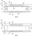
- Figure 7 is an elevation view of the exterior end 212 of the first grommet body 102 shown in Figures 1 through 6 .
- the elevation views show that the slits 240 extend fully through the thickness of the flange 220 along both the first and second sets 138, 140 of the articulated segments 124 on either side of the passageway 122.
- the slits 240 may be linear and parallel to one another.
- the slits 240 may be perpendicular to the lateral length of the first grommet body 102.
- the slits 240 may not extend through the full thickness of the base 218, as indicated by the solid continuous strip 244 of the base 218 shown in Figure 6 .
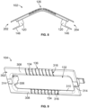
- Figure 8 is a plan view of the first grommet body 102 in a flexed state.
- the first grommet body 102 is bent along the flexible hinge region 126.
- the two latch features 120 are closer together than when the first grommet body 102 is in the non-flexed state shown in Figure 4 .
- a mechanic or other operator may flex the first grommet body 102 to the flexed state shown in Figure 8 during the installation process. For example, the mechanic may squeeze the two lateral ends 202, 204 together as the first grommet body 102 is moved towards and into the opening 118 of the panel 110.
- the closer positioning of the latch features 120 may enable the latch features 120 to clear the edge 116 of the panel 110 and move through the passageway 132 of the second grommet body 104.
- the first grommet body 102 may resiliently return towards the non-flexed state.
- the tabs 146 of the latch features 120 may move into place along the exterior side 148 of the second grommet body 104, as the latch features 120 move farther apart and reorient to the non-flexed state, securing the two grommet bodies 102, 104 in the coupled state.
- Figure 9 is an isometric view of an exterior end 302 of the second grommet body 104 shown in Figures 1 and 2 .
- the exterior end 302 faces away from the panel 110 when installed.
- Figure 10 is an isometric view of a mating end 304 of the second grommet body 104 shown in Figures 1, 2 , and 9 .
- the mating end 304 may extend at least partially into the opening 118 of the panel 110 when installed.
- the second grommet body 104 may include a base (e.g., second base) 306 and a flange (e.g., second flange) 308.
- the base 306 has an inner side 310 that defines the second passageway 132.
- the flange 308 extends from an outer side 312 of the base 306.
- the flange 308 may contact the second side 114 of the panel 110 when installed to block the second grommet body 104 from falling through the opening 118.
- the flange 308 may include landing pads 314 along the exterior side 148.
- the landing pads 314 are depressions or detents that are sized and positioned to receive the tabs 146 of the latch features 120 when the flexible grommet assembly 100 is assembled.
- the second flexible hinge region 136 may be similar to the first flexible hinge region 126 of the first grommet body 102.
- the articulated segments 134 of the flexible hinge region 136 may be defined by the base 306 and the flange 308.
- the articulated segments 134 may be spaced apart by slits 316 and cutouts 318.
- the cutouts 318 extend through the base 306 from the outer side 312 to the inner side 310.
- the slits 316 extend through the thickness of the flange 308. Each slit 316 may be fluidly connected to one corresponding cutout 318.
- the second articulated segments 134 may be T-shaped.
- the latch features 150 of the second grommet body 104 may extend from a mating side 320 of the base 306.
- the base 306 may be between the latch features 150 and the flange 308.
- the latch features 150 may be designed to overlap and optionally contact the first side 112 of the panel 110, as shown in Figure 2 .
- the mechanic or operator may bend the second grommet body 104 at the flexible hinge region 136, similar to the first grommet body 102 as shown in Figure 8 , to enable the latch features 150 to clear the edge 116 of the panel 110.
- the latch features 150 may move into place along the first side 112 of the panel 110 to secure the second grommet body 104 to the panel 110.
- FIG 11 is an isometric view of the flexible grommet assembly 100 installed within an interior cabin 401 of an aircraft 403 according to an example application.
- the interior cabin 401 may be a passenger cabin, a galley, a lavatory, a cockpit, or the like.
- the interior cabin 401 includes a panel 400.
- the panel 400 may be a header panel that extends downward from a ceiling of a cabin. In some examples, including the illustrated example, the panel 400 is curved.
- the flexible grommet assembly 100 is installed to the panel 400 at an opening 404 in the panel 400.
- a bezel 406 is mounted to a front side 402 of the panel 400 and surrounds the flexible grommet assembly 100 and the opening 404.
- the bezel 406 may be a component of a sign, a light, and/or the like.
- the bezel 406 may be part of a lighted sign, such as an illuminated exit sign, lavatory sign, seat belt sign, and/or the like.
- Figure 12 is an isometric view showing a back side 410 of the panel 400 in the interior cabin 401 according to the example application in Figure 11 .
- One or more wires 412 may be routed from the area beyond the panel 400 through the opening 404 and the flexible grommet assembly 100 to the front side 402 of the panel 400.
- the wires 412 may electrically connect to the device with the bezel 406 to provide electrical power and/or control signals to the device.
- the flexible grommet assembly 100 may protect the wires 412 from damage due to rubbing, pinching, and/or snagging on an edge of the panel 400 that forms the opening 404.
- the edge of the panel 400 may be unfinished, and sharp or serrated portions of the edge may damage the wires 412.
- the flexible grommet assembly 100 described herein can be used for various different applications.
- the flexible grommet assembly 100 may be installed on panels of other types of vehicles, such as rail vehicles, road vehicles, marine vessels, and/or the like.
- the flexible grommet assembly 100 can also be used in non-vehicle applications, such as to protect wiring within buildings.
- FIG. 13 is a flow chart 500 of a method of installing a flexible grommet assembly 100 according to an example.
- the method optionally may include at least one additional step than shown, at least one fewer step than shown, and/or at least one different step than shown in Figure 13 .
- a first grommet body 102 is positioned along a first side 112 of a panel 110 at an opening 118 that extends through the panel 110.
- the first grommet body 102 includes first articulated segments 124 that define a first hinge region 126.
- a second grommet body 104 is positioned along a second side 114 of the panel 110 at the opening 118.
- the second grommet body 104 includes second articulated segments 134 that define a second hinge region 136.
- the first and second grommet bodies 102, 104 are coupled together through the opening 118, such that the grommet bodies 102, 104 sandwich the panel 110.
- the first and second grommet bodies 102, 104 are flexed about their respective first and second hinge regions 126, 136 to conform to a curvature in the panel 110.
- the first grommet body 102 may include latch features 120.
- the first hinge region 126 may be disposed between the latch features 120.
- the coupling step may include bending the first grommet body 102 at the first hinge region 126 to force the latch features 120 closer together to clear an edge 116 of the panel 110 as the first grommet body 102 is moved towards the panel 110.
- the latch features 120 may overlap and lock into place behind a portion of the second grommet body 104.
- the flexible grommet assembly 100 may inherently follow the contour of any curvature in the panel 110 due to the flexible hinge regions 126, 136.
- the method optionally may include loading one or more wires 412 through passageways 122, 132 in the first and second grommet bodies 102, 104 and through the opening 118 in the panel 110.
- the first and second grommet bodies 102, 104 may protect the one or more wires 412 from contacting one or more edges 116 of the panel 110 at the opening 118.
- the first and second grommet bodies 102, 104 may be formed via additive manufacturing.
- the first grommet body 102 may be formed by sequentially fusing source material layer by layer according to a build plan.
- additive manufacturing may be used to define the articulated segments 124, 134 of each of the first and second grommet bodies 102, 104.
- the source material may be selectively fused in the shape of the articulated segments 124, 134 with gaps between the articulated segments 124, 134. The gaps may represent the slits 240, 316 and the cutouts 242, 318.
- the overall shape of the grommet bodies 102, 104 and the articulated segments 124, 134 can be formed during a single build process. Furthermore, it may be difficult to achieve the intricate details of the articulated segments 124, 134 by conventional processes, such as molding and subsequent etching or other extraction of material to form the articulated segments 124, 134.
- the first and second grommet bodies 102, 104 may be composed of a plastic material, a flexible metal material, or the like. In some alternative examples, the first and second grommet bodies 102, 104 may be formed via injection molding.
- a flexible grommet assembly comprising: a first grommet body comprising first articulated segments that define a first hinge region; and a second grommet body comprising second articulated segments that define a second hinge region, wherein the first and second grommet bodies are configured to cooperatively couple to an opening of a panel such that the first and second grommet bodies are flexed about their respective first and second hinge regions to conform to a curvature in the panel.
- Clause 2 The flexible grommet assembly of clause 1, wherein the first and second grommet bodies are oblong and the first and second hinge regions are disposed at respective middle sections of the first and second grommet bodies along respective lateral lengths of the first and second grommet bodies.
- Clause 3 The flexible grommet assembly of clause 1 or clause 2, wherein the first grommet body defines a passageway that aligns with the opening, wherein the first hinge region is defined by a first set of the first articulated segments and a second set of the first articulated segments, the first and second sets disposed on opposite sides of the passageway.
- Clause 4 The flexible grommet assembly of any of clauses 1-3, wherein the first grommet body includes latch features, wherein the latch features extend through the opening of the panel and couple to the second grommet body to secure the first grommet body to the second grommet body along opposite sides of the panel.
- Clause 5 The flexible grommet assembly of clause 4, wherein the first hinge region is disposed between the latch features along a lateral length of the first grommet body.
- Clause 6 The flexible grommet assembly of clause 4 or clause 5, wherein the second grommet body defines a second passageway that aligns with the opening in the panel, and the latch features of the first grommet body extend through the second passageway and contact an exterior side of the second grommet body to secure the first grommet body to the second grommet body.
- Clause 7 The flexible grommet assembly of any of clauses 1-6, wherein the first grommet body comprises a base and a flange extending from the base, the base defining a passageway that aligns with the opening in the panel, wherein each of the first articulated segments is defined in part by the base and in part by the flange.
- Clause 8 The flexible grommet assembly of clause 7, wherein the first articulated segments are separated from one another by slits through a thickness of the flange and cutouts in the base, with each cutout being fluidly connected to one corresponding slit.
- Clause 9 The flexible grommet assembly of any of clauses 1-8, wherein the first articulated segments and the second articulated segments are T-shaped.
- Clause 10 The flexible grommet assembly of any of clauses 1-9, wherein the first grommet body includes a continuous strip of solid material extending along a perimeter of a passageway in the first grommet body, wherein the first articulated segments are joined to the continuous strip.
- Clause 11 The flexible grommet assembly of any of clauses 1-10, wherein the second grommet body includes second latch features that extend into the opening of the panel, the second latch features configured to contact a first side of the panel.
- An aircraft comprising: an interior cabin including a curved panel, the curved panel defining an opening therethrough; and a flexible grommet assembly installed on the curved panel, the flexible grommet assembly comprising a first grommet body and a second grommet body, the first grommet body including first articulated segments that define a first hinge region, the second grommet body including second articulated segments that define a second hinge region, wherein the first and second grommet bodies are configured to cooperatively couple to the opening of the curved panel such that the first and second grommet bodies are flexed about their respective first and second hinge regions to conform to a curvature in the curved panel.
- Clause 13 The aircraft of clause 12, wherein the first articulated segments contact a first edge of the curved panel that defines the opening along a first side of the curved panel and the second articulated segments contact a second edge of the curved panel that defines the opening along a second side of the curved panel.
- Clause 14 The aircraft of clause 12 or clause 13, wherein the first articulated segments and the second articulated segments are T-shaped.
- Clause 15 The aircraft of any of clauses 12-14, wherein the first grommet body includes a continuous strip of solid material extending along a perimeter of a passageway in the first grommet body, wherein the first articulated segments are joined to the continuous strip.
- Clause 16 The aircraft of any of clauses 12-15, wherein the first grommet body comprises a base and a flange extending from the base, the base defining a passageway that aligns with the opening in the panel, wherein each of the first articulated segments is defined in part by the base and in part by the flange.
- Clause 17 The aircraft of clause 16, wherein the first articulated segments are separated from one another by slits through a thickness of the flange and cutouts in the base, with each cutout being fluidly connected to one corresponding slit.
- a method of installing a flexible grommet assembly on a panel comprising: positioning a first grommet body along a first side of a panel at an opening that extends through the panel, the first grommet body comprising first articulated segments that define a first hinge region; positioning a second grommet body along a second side of the panel at the opening, the second side opposite the first side, the second grommet body comprising second articulated segments that define a second hinge region; and coupling the first and second grommet bodies together through the opening such that the first and second grommet bodies are flexed about their respective first and second hinge regions to conform to a curvature in the panel.
- Clause 19 The method of clause 18, wherein the first grommet body includes latch features with the first hinge region disposed between the latch features, and wherein coupling the first and second grommet bodies together comprises bending the first grommet body at the first hinge region to force the latch features closer together to clear an edge of the panel as the first grommet body is moved towards the panel.
- Clause 20 The method of clause 18 or clause 19, further comprising loading one or more wires through passageways in the first and second grommet bodies and through the opening in the panel, wherein the first and second grommet bodies protect the one or more wires from contacting an edge of the panel at the opening.
- orientations shown in the drawings can be inverted, rotated, or otherwise changed, such that an upper portion is a lower portion, and vice versa, horizontal becomes vertical, and the like.
- a structure, limitation, or element that is "configured to” perform a task or operation is particularly structurally formed, constructed, or adapted in a manner corresponding to the task or operation.
- an object that is merely capable of being modified to perform the task or operation is not “configured to” perform the task or operation as used herein.
Landscapes
- Engineering & Computer Science (AREA)
- Architecture (AREA)
- Civil Engineering (AREA)
- Structural Engineering (AREA)
- Insulating Bodies (AREA)
- Installation Of Indoor Wiring (AREA)
- Aviation & Aerospace Engineering (AREA)
- Manufacturing & Machinery (AREA)
- Connection Of Plates (AREA)
- Mechanical Engineering (AREA)
- Transportation (AREA)
Abstract
Description
- The present disclosure generally relates to grommets that couple to panels and surround one or more objects that extend through the panels.
- Grommets are installed on panels at openings in the panel to protect an interface between a panel edge of the opening and the one or more objects that are routed through the opening. Typically, grommets are used to protect wires and wire harnesses from damage due to rubbing along the rough texture of the panel edge. Some industries and applications may require the use of grommets when routing electrical wires through panels. Known snap grommets, which include two parts that snap together to sandwich the panel, are designed for planar panels, and may not function well if the panel is curved. For example, the two parts of known snap grommets may not be able to couple together on a curved panel due to the latching features not properly aligning. Even if the known snap grommet could couple to the curved panel, the snap grommet would not conform to the curved contour, which would frustrate the purpose of the snap grommet. For example, along a concave surface, the snap grommet may separate from the panel edge, which could allow the wires to rub against the rough panel edge.
- A conventional process of installing grommets on curved panels is to glue the grommet in place, rather than use a snap grommet. For example, a mechanic may measure and cut a grommet to size, and then glue the grommet to the curved panel. This process is time-consuming, considering the assembly time and cure time. The use of adhesive can also be messy, requiring an additional clean-up step.
- A need exists for a flexible snap grommet assembly that can be universally applied on planar panels and curved panels, while reliably and satisfactorily protecting the objects that extend through the panel opening.
- With those needs in mind, certain examples of the present disclosure provide a flexible grommet assembly that includes a first grommet body and a second grommet body. The first grommet body includes first articulated segments that define a first hinge region. The second grommet body includes second articulated segments that define a second hinge region. The first and second grommet bodies are configured to cooperatively couple to an opening of a panel such that the first and second grommet bodies are flexed about their respective first and second hinge regions to conform to a curvature in the panel.
- Certain examples of the present disclosure provide an aircraft that includes an interior cabin and a flexible grommet assembly. The interior cabin includes a curved panel that defines an opening therethrough. The flexible grommet assembly is installed on the curved panel. The flexible grommet assembly includes a first grommet body and a second grommet body. The first grommet body includes first articulated segments that define a first hinge region, and the second grommet body includes second articulated segments that define a second hinge region. The first and second grommet bodies are configured to cooperatively couple to the opening of the curved panel such that the first and second grommet bodies are flexed about their respective first and second hinge regions to conform to a curvature in the curved panel.
- Certain examples of the present disclosure provide a method of installing a flexible grommet assembly on a panel. The method includes positioning a first grommet body along a first side of a panel at an opening that extends through the panel, and positioning a second grommet body along a second side of the panel at the opening. The second side is opposite the first side. The first grommet body includes first articulated segments that define a first hinge region. The second grommet body includes second articulated segments that define a second hinge region. The method includes coupling the first and second grommet bodies together through the opening such that the first and second grommet bodies are flexed about their respective first and second hinge regions to conform to a curvature in the panel.
- These and other features, and advantages of the present disclosure will become better understood when the following detailed description is read with reference to the accompanying drawings in which like numerals represent like parts throughout the drawings, wherein:
-
Figure 1 is an isometric view of a flexible grommet assembly. -
Figure 2 is a plan view of the flexible grommet assembly installed on a panel. -
Figure 3 is an isometric view of a first grommet body of the flexible grommet assembly shown inFigures 1 and 2 . -
Figure 4 is a plan view of the first grommet body shown inFigures 1 through 3 . -
Figure 5 is an enlarged view of a portion of the first grommet body inFigure 4 , showing a flexible hinge region. -
Figure 6 is an elevation view of a mating end of the first grommet body according to the example shown inFigures 1 through 5 . -
Figure 7 is an elevation view of an exterior end of the first grommet body shown inFigures 1 through 6 . -
Figure 8 is a plan view of the first grommet body in a flexed state. -
Figure 9 is an isometric view of an exterior end of a second grommet body of the flexible grommet assembly shown inFigures 1 and 2 . -
Figure 10 is an isometric view of a mating end of the second grommet body shown inFigures 1, 2 , and9 . -
Figure 11 is an isometric view of the flexible grommet assembly installed on a front side of a panel according to an example application. -
Figure 12 is an isometric view showing a back side of the panel according to the example application inFigure 11 . -
Figure 13 is a flow chart of a method of installing a flexible grommet assembly on a panel. - The foregoing summary, as well as the following detailed description of certain examples will be better understood when read in conjunction with the appended drawings. As used herein, an element or step recited in the singular and preceded by the word "a" or "an" should be understood as not necessarily excluding the plural of the elements or steps. Further, references to "one example" are not intended to be interpreted as excluding the existence of additional examples that also incorporate the recited features. Moreover, unless explicitly stated to the contrary, examples "comprising" or "having" an element or a plurality of elements having a particular condition can include additional elements not having that condition.
- Examples of the present disclosure provide a flexible grommet assembly that can flex to conform to a curved panel onto which the flexible grommet assembly is installed. For example, the flexible grommet assembly includes integrated flexible hinges within the respective bodies of first and second grommets of the flexible grommet assembly. The hinges enable the flexible grommet assembly to be installed on flat panels as well as curved panels (e.g., concave or convex), without customizing the grommet assembly. For example, upon snapping the grommet assembly onto a curved panel, the flexible hinges enable the first and second grommet bodies to follow the contour of the panel and remain in contact with an edge of a panel opening. By remaining in intimate proximity of the panel edge, the first and second grommet bodies protect one or more objects that pass through the panel opening, such as wires, from damage caused by rubbing against the panel edge. The flexible grommet assembly is designed to be quickly installed by snapping the first and second grommet bodies together from opposite sides of the panel. The flexible grommet assembly can avoid drawbacks associated with installing custom grommets on curved panels, including the effort, cost, safety risk, and/or clean-up attributable to measuring, cutting, and gluing the grommet into place. The installation of the flexible grommet assembly, according to the examples herein, on a curved panel may be substantially quicker, easier, cheaper, cleaner, and/or safer than the known process that involves cutting and gluing. A curved panel as described herein refers to a non-planar section of a panel that surrounds and defines an opening or pass-through window for receiving wires and/or other objects therethrough.
-
Figure 1 is an isometric view of aflexible grommet assembly 100 according to an example. Theflexible grommet assembly 100 includes afirst grommet body 102 and thesecond grommet body 104. The first andsecond grommet bodies Figure 1 shows thegrommet bodies grommet bodies -
Figure 2 is a plan view of theflexible grommet assembly 100 installed on apanel 110. Thepanel 110 is shown in cross-section inFigure 2 to avoid obstructing the view of theflexible grommet assembly 100. Thepanel 110 has afirst side 112 and asecond side 114 opposite thefirst side 112. Thepanel 110 may have a one-piece construction or may be a composite. Thepanel 110 includes anedge 116 that defines anopening 118. Theopening 118 extends through a thickness of thepanel 110 from thefirst side 112 to thesecond side 114. The section of thepanel 110 shown inFigure 2 is planar. As described above, theflexible grommet assembly 100 is designed to flex and bend, if necessary, to conform to curved panel sections. When installed on thepanel 110, the first andsecond grommet bodies Figure 1 and sandwich thepanel 110. Portions of thegrommet bodies opening 118 to engage and secure to the respective opposinggrommet body Figures 1 and 2 . - The
first grommet body 102 includes first latch features 120 and defines a first passageway 122 (e.g., grommet opening). Thefirst passageway 122 aligns with theopening 118 of thepanel 110 when installed and receives wires and/or other objects therethrough. In some examples, including the illustrated example, thefirst grommet body 102 is box-shaped, and thefirst passageway 122 is framed by the box-shapedfirst grommet body 102. Thefirst passageway 122 is obstructed from view inFigure 2 by an upper segment of thefirst grommet body 102. The first latch features 120 are designed to extend through theopening 118 of thepanel 110 and couple to thesecond grommet body 104 to secure theflexible grommet assembly 100 onto thepanel 110. For example, the first latch features 120 may prohibit the first andsecond grommet bodies grommet bodies panel 110 sandwiched therebetween. - The
first grommet body 102 includes first articulatedsegments 124 that collectively represent a firstflexible hinge region 126. In some examples, the articulatedsegments 124 are integral portions of thefirst grommet body 102 that are formed by the presence of negative spaces along thebody 102. For example, the articulatedsegments 124 may not be discrete elements that are attached to thefirst grommet body 102 after thefirst grommet body 102 is formed. The articulatedsegments 124 may be inherently formed during a manufacturing process that generates thefirst grommet body 102, such that the articulated segments are formed concurrently with other portions of thefirst grommet body 102. The negative spaces may include slits, holes (referred to herein as cutouts), and/or the like. The firstflexible hinge region 126 includes multiple articulatedsegments 124 in a row. The articulatedsegments 124 in the row are defined, and separated from each other, by the negative spaces. In some examples, as shown in greater detail inFigures 3 ,6, and 7 , the firstflexible hinge region 126 includes afirst set 128 of the first articulatedsegments 124 and asecond set 130 of the first articulatedsegments 124. The first andsecond sets passageway 122. In the illustrated orientation inFigure 1 , thefirst set 128 is above thepassageway 122 and thesecond set 130 is below thepassageway 122. Each of the first andsecond sets first set 128 laterally aligns with thesecond set 130 along a lateral length of thefirst grommet body 102. In some examples, the first andsecond sets middle section 131 of thefirst grommet body 102 along the lateral length, such that theflexible hinge region 126 is disposed at themiddle section 131. - The
second grommet body 104 defines a second passageway 132 (e.g., grommet opening) that aligns with theopening 118 of thepanel 110 when installed and receives the wires and/or other objects therethrough. In some examples, including the illustrated example, thesecond grommet body 104 is box-shaped, and thesecond passageway 132 is framed by the box-shapedsecond grommet body 104. Thesecond passageway 132 is obstructed from view inFigure 2 by an upper segment of thesecond grommet body 104. - The
second grommet body 104 includes second articulatedsegments 134 that collectively represent a secondflexible hinge region 136. The first and secondflexible hinge regions flexible grommet assembly 100 are designed to flex to conform to the curvature, if any, of thepanel 110. In some examples, including the illustrated example in which thepanel 110 is planar, theflexible hinge regions panel 110 is curved, the first andsecond grommet bodies flexible hinge regions grommet bodies edge 116 of thepanel 110 along the entire perimeter of theopening 118. Theflexible grommet assembly 100 can protect the wires or other objects that extend through the opening 118 from rubbing against the rough,unfinished edge 116 of thepanel 110, regardless of whether thepanel 110 is planar or curved. The first and secondflexible hinge regions second grommet bodies Figures 1 and 2 . Theflexible hinge regions flexible grommet assembly 100 to flex in two directions about acentral axis 144. Theflexible hinge regions flexible hinge regions flexible grommet assembly 100 about a lateral axis that is perpendicular to thecentral axis 144. - The articulated
segments 134 may be integral portions of thesecond grommet body 104 that are formed by the presence of negative spaces along thesecond grommet body 104. For example, the articulatedsegments 134 may not be discrete elements that are attached to thesecond grommet body 104 after thesecond grommet body 104 is formed. The articulatedsegments 134 may be inherently formed during a manufacturing process that generates thesecond grommet body 104, such that the articulated segments are formed concurrently with other portions of thesecond grommet body 104. The negative spaces may include slits, cutouts, and/or the like. The secondflexible hinge region 136 includes multiple articulatedsegments 134 in a row. The articulatedsegments 134 in the row are defined, and separated from each other, by the negative spaces. As shown inFigure 2 , the first articulatedsegments 124 of thefirst grommet body 102 and the second articulatedsegments 134 of thesecond grommet body 104 may be T-shaped. - In some examples, as shown in greater detail in
Figures 8 and 9 , the secondflexible hinge region 136 includes afirst set 138 of the second articulatedsegments 134 and asecond set 140 of the second articulatedsegments 134. The first andsecond sets passageway 132. In the illustrated orientation inFigure 1 , thefirst set 138 is above thepassageway 132, and thesecond set 140 is below thepassageway 132. Each of the first andsecond sets first set 138 laterally aligns with thesecond set 140 along a lateral length of thesecond grommet body 104. In some examples, the first andsecond sets middle section 141 of thesecond grommet body 104 along the lateral length, such that theflexible hinge region 136 is disposed at themiddle section 141. - In some examples, including the illustrated example, when in the coupled state, the latch features 120 of the
first grommet body 102 extend through theopening 118 in thepanel 110 and couple to thesecond grommet body 104 to secure theflexible grommet assembly 100 onto thepanel 110. Thefirst grommet body 102 inFigure 2 aligns (or generally aligns) with thefirst side 112 of thepanel 110. A portion of thefirst grommet body 102 may abut against thefirst side 112. The latch features 120 may protrude beyond thesecond side 114 of thepanel 110. The latch features 120 may be hook-shaped (or generally hook-shaped) withtabs 146 that overlap and contact anexterior side 148 of thesecond grommet body 104 in the coupled state. Optionally, thetabs 146 may contact thesecond side 114 of thepanel 110 in addition to, or instead of, contacting theexterior side 148 of thesecond grommet body 104. Thefirst grommet body 102 may be referred to herein as amale grommet body 102 and thesecond grommet body 104 may be referred to as afemale grommet body 104 because the first latch features 120 secure to the second orfemale grommet body 104. - In some examples, the second (e.g., female)
grommet body 104 includes second latch features 150. The second latch features 150 may extend through theopening 118 of thepanel 110 from thesecond grommet body 104 which aligns (or generally aligns) with thesecond side 114 of thepanel 110. The second latch features 150 may contact thefirst side 112 of thepanel 110. In some examples, including the illustrated example, the second latch features 150 secure thesecond grommet body 104 to thepanel 110, and the first latch features 120 couple thefirst grommet body 102 to thesecond grommet body 104. The first latch features 120 of thefirst grommet body 102 may have a different shape and/or size than the second latch features 150 of thesecond grommet body 104. For example, the first latch features 120 may be larger than the second latch features 150. In a first alternative example, the second latch features 150 may contact and latch onto thefirst grommet body 102. In a second alternative example, thesecond grommet body 104 has no latch features. For example, the engagement of the latch features 120 with thesecond grommet body 104 may secure the twogrommet bodies panel 110. -
Figure 3 is an isometric view of the first (e.g., male)grommet body 102 of theflexible grommet assembly 100 shown inFigures 1 and 2 . Thefirst grommet body 102 extends a lateral length from a firstlateral end 202 to a second lateral end 204 (opposite the first lateral end 202). In some examples, including the illustrated example, thefirst grommet body 102 has an oblong shape. The lateral length of thefirst grommet body 102 is the greatest dimension of thefirst grommet body 102. For example, the lateral length is greater than a height of thefirst grommet body 102 from atop end 206 to abottom end 208 of thefirst grommet body 102. The reference to top and bottom ends is merely for identification purposes and does not require a specific orientation of thefirst grommet body 102 relative to thepanel 110. The lateral length is also greater than a depth of thefirst grommet body 102 from amating end 210 to anexterior end 212 of thefirst grommet body 102. Themating end 210 interfaces with thepanel 110 and/or thesecond grommet body 104 when installed, and theexterior end 212 faces away from thepanel 110. Thepassageway 122 defined by thefirst grommet body 102 may be oblong. The lateral length between a first lateral end 214 of thepassageway 122 and a secondlateral end 216 of thepassageway 122 may be the greatest dimension of thepassageway 122. For example, thepassageway 122 may be rectangular, elliptical, oval, or the like. In other examples, thepassageway 122 may be circular, square, or another non-oblong shape. - In some examples, the
first grommet body 102 includesbase 218 and aflange 220. Thebase 218 has aninner side 222 that defines the perimeter of thepassageway 122. Theinner side 222 may be relatively narrow/thin. Theflange 220 extends from anouter side 226 of thebase 218. Theouter side 226 is opposite theinner side 222. Thebase 218 has amating side 228 and a mountingside 230 that is opposite themating side 228. Theflange 220 may be disposed on the mountingside 230. Theflange 220 may be a thin panel. When installed, theflange 220 may overlap thefirst side 112 of thepanel 110 shown inFigure 2 . Theflange 220 may abut thefirst side 112 to block thefirst grommet body 102 from falling through theopening 118 of thepanel 110. The latch features 120 of thefirst grommet body 102 may project from themating side 228 of thebase 218. Theflange 220 optionally may be segmented into afirst flange portion 220A and asecond flange portion 220B disposed on opposite sides of thepassageway 122. Alternatively, theflange 220 may continuously extend around the full perimeter of thepassageway 122. - In some examples, the
first grommet body 102 includes two latch features 120 that are laterally spaced apart from each other. For example, thepassageway 122 may be disposed between the two latch features 120. Theflexible hinge region 126 may be spaced apart from the latch features 120 along the lateral length. For example, theflexible hinge region 126 may be located between the two latch features 120. Themiddle section 131, which includes theflexible hinge region 126, may be disposed between afirst end segment 232 and asecond end segment 234 of thefirst grommet body 102. Thefirst end segment 232 includes a first (e.g., left)latch feature 120A of the latch features 120 and defines the first lateral end 214 of thepassageway 122. Thesecond end segment 234 includes a second (e.g., right)latch feature 120B of the latch features 120 and defines the secondlateral end 216 of thepassageway 122. The articulatedsegments 124 of theflexible hinge 126 enable thefirst grommet body 102 to flex in two directions about acentral axis 236 of thefirst grommet body 102. Thecentral axis 236 may extend along the height of thefirst grommet body 102. -
Figure 4 is a plan view of thefirst grommet body 102 shown inFigures 1 through 3 .Figure 5 is an enlarged view of a portion of thefirst grommet body 102 inFigure 4 , showing theflexible hinge region 126. In some examples, the articulatedsegments 124 are defined by thebase 218 and theflange 220. For example, a first portion of each articulatedsegment 124 is defined by theflange 220 and a second portion is defined by thebase 218. In some examples, including the illustrated example, the articulatedsegments 124 are separated from one another byslits 240 and cutouts 242 (e.g., holes). Theslits 240 extend through a thickness of theflange 220. Theslits 240 are open along theexterior end 212 of thefirst grommet body 102. Thecutouts 242 are defined through thebase 218. For example, thecutouts 242 extend through the base 218 from theouter side 226 to theinner side 222. Eachcutout 242 may be fluidly connected to onecorresponding slit 240 of theslits 240. In some examples, the articulatedsegments 124 are T-shaped, and theslits 240 andcutouts 242 define inverted T-shaped negative spaces between the articulatedsegments 124. - In some examples, the
mating side 228 of thebase 218 is defined by a continuous strip (e.g., length) 244 of solid material extending around a perimeter of thepassageway 122. The T-shaped articulatedsegments 124 of theflexible hinge region 126 are attached to thecontinuous strip 244. For example, each articulatedsegment 124 may include abroad portion 246 and anarrow portion 248. Thebroad portion 246 has a greater lateral length than thenarrow portion 248. Thenarrow portion 248 is disposed between thebroad portion 246 and thecontinuous strip 244 of thebase 218. The articulatedsegment 124 may be cantilevered such that thebroad portion 246 is connected to thecontinuous strip 244 via thenarrow portion 248. Thecontinuous strip 244 may define a flexible joint to which all of the articulatedsegments 124 are connected. Thebroad portions 246 of the articulatedsegments 124 in the row are separated by theslits 240. Thenarrow portions 248 of the articulatedsegments 124 in the row are separated by thecutouts 242. In some examples, thenarrow portions 248 are part of thebase 218. Thebroad portions 246 may be defined by both thebase 218 and theflange 220. In some examples, when installed on thepanel 110, themating side 228 of the base 218 may extend at least partially into theopening 118 of thepanel 110 and theflange 220 remains outside of theopening 118. -
Figure 6 is an elevation view of themating end 210 of thefirst grommet body 102 according to the example shown inFigures 1 through 5 .Figure 7 is an elevation view of theexterior end 212 of thefirst grommet body 102 shown inFigures 1 through 6 . The elevation views show that theslits 240 extend fully through the thickness of theflange 220 along both the first andsecond sets segments 124 on either side of thepassageway 122. Theslits 240 may be linear and parallel to one another. For example, theslits 240 may be perpendicular to the lateral length of thefirst grommet body 102. Theslits 240 may not extend through the full thickness of thebase 218, as indicated by the solidcontinuous strip 244 of the base 218 shown inFigure 6 . -
Figure 8 is a plan view of thefirst grommet body 102 in a flexed state. Thefirst grommet body 102 is bent along theflexible hinge region 126. In the illustrated flexed state, the two latch features 120 are closer together than when thefirst grommet body 102 is in the non-flexed state shown inFigure 4 . A mechanic or other operator may flex thefirst grommet body 102 to the flexed state shown inFigure 8 during the installation process. For example, the mechanic may squeeze the two lateral ends 202, 204 together as thefirst grommet body 102 is moved towards and into theopening 118 of thepanel 110. The closer positioning of the latch features 120 may enable the latch features 120 to clear theedge 116 of thepanel 110 and move through thepassageway 132 of thesecond grommet body 104. As the mechanic releases the compressive force, thefirst grommet body 102 may resiliently return towards the non-flexed state. Thetabs 146 of the latch features 120 may move into place along theexterior side 148 of thesecond grommet body 104, as the latch features 120 move farther apart and reorient to the non-flexed state, securing the twogrommet bodies -
Figure 9 is an isometric view of anexterior end 302 of thesecond grommet body 104 shown inFigures 1 and 2 . Theexterior end 302 faces away from thepanel 110 when installed.Figure 10 is an isometric view of amating end 304 of thesecond grommet body 104 shown inFigures 1, 2 , and9 . Themating end 304 may extend at least partially into theopening 118 of thepanel 110 when installed. Thesecond grommet body 104 may include a base (e.g., second base) 306 and a flange (e.g., second flange) 308. Thebase 306 has aninner side 310 that defines thesecond passageway 132. Theflange 308 extends from anouter side 312 of thebase 306. Theflange 308 may contact thesecond side 114 of thepanel 110 when installed to block thesecond grommet body 104 from falling through theopening 118. Optionally, theflange 308 may include landingpads 314 along theexterior side 148. Thelanding pads 314 are depressions or detents that are sized and positioned to receive thetabs 146 of the latch features 120 when theflexible grommet assembly 100 is assembled. - The second
flexible hinge region 136 may be similar to the firstflexible hinge region 126 of thefirst grommet body 102. For example, the articulatedsegments 134 of theflexible hinge region 136 may be defined by thebase 306 and theflange 308. The articulatedsegments 134 may be spaced apart byslits 316 andcutouts 318. Thecutouts 318 extend through the base 306 from theouter side 312 to theinner side 310. Theslits 316 extend through the thickness of theflange 308. Eachslit 316 may be fluidly connected to one correspondingcutout 318. The second articulatedsegments 134 may be T-shaped. The latch features 150 of thesecond grommet body 104 may extend from a mating side 320 of thebase 306. The base 306 may be between the latch features 150 and theflange 308. The latch features 150 may be designed to overlap and optionally contact thefirst side 112 of thepanel 110, as shown inFigure 2 . During the installation process, the mechanic or operator may bend thesecond grommet body 104 at theflexible hinge region 136, similar to thefirst grommet body 102 as shown inFigure 8 , to enable the latch features 150 to clear theedge 116 of thepanel 110. As thesecond grommet body 104 resiles, the latch features 150 may move into place along thefirst side 112 of thepanel 110 to secure thesecond grommet body 104 to thepanel 110. -
Figure 11 is an isometric view of theflexible grommet assembly 100 installed within aninterior cabin 401 of anaircraft 403 according to an example application. Theinterior cabin 401 may be a passenger cabin, a galley, a lavatory, a cockpit, or the like. Theinterior cabin 401 includes apanel 400. Thepanel 400 may be a header panel that extends downward from a ceiling of a cabin. In some examples, including the illustrated example, thepanel 400 is curved. Theflexible grommet assembly 100 is installed to thepanel 400 at anopening 404 in thepanel 400. Abezel 406 is mounted to afront side 402 of thepanel 400 and surrounds theflexible grommet assembly 100 and theopening 404. Thebezel 406 may be a component of a sign, a light, and/or the like. For example, thebezel 406 may be part of a lighted sign, such as an illuminated exit sign, lavatory sign, seat belt sign, and/or the like. -
Figure 12 is an isometric view showing aback side 410 of thepanel 400 in theinterior cabin 401 according to the example application inFigure 11 . One ormore wires 412 may be routed from the area beyond thepanel 400 through theopening 404 and theflexible grommet assembly 100 to thefront side 402 of thepanel 400. Thewires 412 may electrically connect to the device with thebezel 406 to provide electrical power and/or control signals to the device. Theflexible grommet assembly 100 may protect thewires 412 from damage due to rubbing, pinching, and/or snagging on an edge of thepanel 400 that forms theopening 404. The edge of thepanel 400 may be unfinished, and sharp or serrated portions of the edge may damage thewires 412. - The
flexible grommet assembly 100 described herein can be used for various different applications. For example, theflexible grommet assembly 100 may be installed on panels of other types of vehicles, such as rail vehicles, road vehicles, marine vessels, and/or the like. Theflexible grommet assembly 100 can also be used in non-vehicle applications, such as to protect wiring within buildings. -
Figure 13 is aflow chart 500 of a method of installing aflexible grommet assembly 100 according to an example. The method optionally may include at least one additional step than shown, at least one fewer step than shown, and/or at least one different step than shown inFigure 13 . Atstep 502, afirst grommet body 102 is positioned along afirst side 112 of apanel 110 at anopening 118 that extends through thepanel 110. Thefirst grommet body 102 includes first articulatedsegments 124 that define afirst hinge region 126. Atstep 504, asecond grommet body 104 is positioned along asecond side 114 of thepanel 110 at theopening 118. Thesecond grommet body 104 includes second articulatedsegments 134 that define asecond hinge region 136. - At
step 506, the first andsecond grommet bodies opening 118, such that thegrommet bodies panel 110. When coupled, the first andsecond grommet bodies second hinge regions panel 110. Thefirst grommet body 102 may include latch features 120. Thefirst hinge region 126 may be disposed between the latch features 120. The coupling step may include bending thefirst grommet body 102 at thefirst hinge region 126 to force the latch features 120 closer together to clear anedge 116 of thepanel 110 as thefirst grommet body 102 is moved towards thepanel 110. Upon returning to the uncompressed or non-flexed state, the latch features 120 may overlap and lock into place behind a portion of thesecond grommet body 104. Theflexible grommet assembly 100 may inherently follow the contour of any curvature in thepanel 110 due to theflexible hinge regions - The method optionally may include loading one or
more wires 412 throughpassageways second grommet bodies opening 118 in thepanel 110. The first andsecond grommet bodies more wires 412 from contacting one ormore edges 116 of thepanel 110 at theopening 118. - In some examples, the first and
second grommet bodies first grommet body 102 may be formed by sequentially fusing source material layer by layer according to a build plan. Furthermore, additive manufacturing may be used to define the articulatedsegments second grommet bodies segments segments slits cutouts grommet bodies grommet bodies segments segments segments second grommet bodies second grommet bodies - Clause 1: A flexible grommet assembly comprising: a first grommet body comprising first articulated segments that define a first hinge region; and a second grommet body comprising second articulated segments that define a second hinge region, wherein the first and second grommet bodies are configured to cooperatively couple to an opening of a panel such that the first and second grommet bodies are flexed about their respective first and second hinge regions to conform to a curvature in the panel.
- Clause 2: The flexible grommet assembly of clause 1, wherein the first and second grommet bodies are oblong and the first and second hinge regions are disposed at respective middle sections of the first and second grommet bodies along respective lateral lengths of the first and second grommet bodies.
- Clause 3: The flexible grommet assembly of clause 1 or clause 2, wherein the first grommet body defines a passageway that aligns with the opening, wherein the first hinge region is defined by a first set of the first articulated segments and a second set of the first articulated segments, the first and second sets disposed on opposite sides of the passageway.
- Clause 4: The flexible grommet assembly of any of clauses 1-3, wherein the first grommet body includes latch features, wherein the latch features extend through the opening of the panel and couple to the second grommet body to secure the first grommet body to the second grommet body along opposite sides of the panel.
- Clause 5: The flexible grommet assembly of clause 4, wherein the first hinge region is disposed between the latch features along a lateral length of the first grommet body.
- Clause 6: The flexible grommet assembly of clause 4 or clause 5, wherein the second grommet body defines a second passageway that aligns with the opening in the panel, and the latch features of the first grommet body extend through the second passageway and contact an exterior side of the second grommet body to secure the first grommet body to the second grommet body.
- Clause 7: The flexible grommet assembly of any of clauses 1-6, wherein the first grommet body comprises a base and a flange extending from the base, the base defining a passageway that aligns with the opening in the panel, wherein each of the first articulated segments is defined in part by the base and in part by the flange.
- Clause 8: The flexible grommet assembly of clause 7, wherein the first articulated segments are separated from one another by slits through a thickness of the flange and cutouts in the base, with each cutout being fluidly connected to one corresponding slit.
- Clause 9: The flexible grommet assembly of any of clauses 1-8, wherein the first articulated segments and the second articulated segments are T-shaped.
- Clause 10: The flexible grommet assembly of any of clauses 1-9, wherein the first grommet body includes a continuous strip of solid material extending along a perimeter of a passageway in the first grommet body, wherein the first articulated segments are joined to the continuous strip.
- Clause 11: The flexible grommet assembly of any of clauses 1-10, wherein the second grommet body includes second latch features that extend into the opening of the panel, the second latch features configured to contact a first side of the panel.
- Clause 12: An aircraft comprising: an interior cabin including a curved panel, the curved panel defining an opening therethrough; and a flexible grommet assembly installed on the curved panel, the flexible grommet assembly comprising a first grommet body and a second grommet body, the first grommet body including first articulated segments that define a first hinge region, the second grommet body including second articulated segments that define a second hinge region, wherein the first and second grommet bodies are configured to cooperatively couple to the opening of the curved panel such that the first and second grommet bodies are flexed about their respective first and second hinge regions to conform to a curvature in the curved panel.
- Clause 13: The aircraft of clause 12, wherein the first articulated segments contact a first edge of the curved panel that defines the opening along a first side of the curved panel and the second articulated segments contact a second edge of the curved panel that defines the opening along a second side of the curved panel.
- Clause 14:. The aircraft of clause 12 or clause 13, wherein the first articulated segments and the second articulated segments are T-shaped.
- Clause 15: The aircraft of any of clauses 12-14, wherein the first grommet body includes a continuous strip of solid material extending along a perimeter of a passageway in the first grommet body, wherein the first articulated segments are joined to the continuous strip.
- Clause 16: The aircraft of any of clauses 12-15, wherein the first grommet body comprises a base and a flange extending from the base, the base defining a passageway that aligns with the opening in the panel, wherein each of the first articulated segments is defined in part by the base and in part by the flange.
- Clause 17: The aircraft of clause 16, wherein the first articulated segments are separated from one another by slits through a thickness of the flange and cutouts in the base, with each cutout being fluidly connected to one corresponding slit.
- Clause 18: A method of installing a flexible grommet assembly on a panel, the method comprising: positioning a first grommet body along a first side of a panel at an opening that extends through the panel, the first grommet body comprising first articulated segments that define a first hinge region; positioning a second grommet body along a second side of the panel at the opening, the second side opposite the first side, the second grommet body comprising second articulated segments that define a second hinge region; and coupling the first and second grommet bodies together through the opening such that the first and second grommet bodies are flexed about their respective first and second hinge regions to conform to a curvature in the panel.
- Clause 19: The method of clause 18, wherein the first grommet body includes latch features with the first hinge region disposed between the latch features, and wherein coupling the first and second grommet bodies together comprises bending the first grommet body at the first hinge region to force the latch features closer together to clear an edge of the panel as the first grommet body is moved towards the panel.
- Clause 20: The method of clause 18 or clause 19, further comprising loading one or more wires through passageways in the first and second grommet bodies and through the opening in the panel, wherein the first and second grommet bodies protect the one or more wires from contacting an edge of the panel at the opening.
- While various spatial and direction terms such as top, bottom, lower, mid, lateral, horizontal, vertical, front and the like can be used to describe examples of the present disclosure, it is understood that such terms are merely used with respect to the orientations shown in the drawings. The orientations can be inverted, rotated, or otherwise changed, such that an upper portion is a lower portion, and vice versa, horizontal becomes vertical, and the like.
- As used herein, a structure, limitation, or element that is "configured to" perform a task or operation is particularly structurally formed, constructed, or adapted in a manner corresponding to the task or operation. For purposes of clarity and the avoidance of doubt, an object that is merely capable of being modified to perform the task or operation is not "configured to" perform the task or operation as used herein.
- It is to be understood that the above description is intended to be illustrative, and not restrictive. For example, the above-described examples can be used in combination with each other. In addition, many modifications can be made to adapt a particular situation or material to the teachings of the various examples of the disclosure without departing from the scope of the claims. While the dimensions and types of materials described herein are intended to define the parameters of the various examples of the disclosure, the examples are by no means limiting and are exemplary. Many other examples will be apparent to those of skill in the art upon reviewing the above description. The scope of the various examples of the disclosure should, therefore, be determined with reference to the appended claims. In the appended claims and the detailed description herein, the terms "including" and "in which" are used as the plain-English equivalents of the respective terms "comprising" and "wherein." Moreover, the terms "first," "second," and "third," etc. are used merely as labels, and are not intended to impose numerical requirements on their objects.
- This written description uses examples to disclose the various examples of the disclosure, including the best mode, and also to enable any person skilled in the art to practice the various examples of the disclosure, including making and using any devices or systems and performing any incorporated methods. The patentable scope is defined by the claims, and can include other examples that occur to those skilled in the art.
Claims (15)
- A flexible grommet assembly (100) comprising:a first grommet body (102) comprising first articulated segments (124) that define a first hinge region (126); anda second grommet body (104) comprising second articulated segments (134) that define a second hinge region (136), wherein the first and second grommet bodies (102, 104) are configured to cooperatively couple to an opening (118, 404) of a panel (110, 400) such that the first and second grommet bodies (102, 104) are flexed about their respective first and second hinge regions (136) to conform to a curvature in the panel (110, 400).
- The flexible grommet assembly (100) of claim 1, wherein the first and second grommet bodies (102, 104) are oblong and the first and second hinge regions (126, 136) are disposed at respective middle sections (131, 141) of the first and second grommet bodies (102, 104) along respective lateral lengths of the first and second grommet bodies (102, 104).
- The flexible grommet assembly (100) of claim 1 or 2, wherein the first grommet body (102) defines a passageway (122) that aligns with the opening (118, 404), wherein the first hinge region (126) is defined by a first set (128) of the first articulated segments (124) and a second set (130) of the first articulated segments (124), the first and second sets (128, 130) disposed on opposite sides of the passageway (122).
- The flexible grommet assembly (100) of any preceding claim, wherein:the first grommet body (102) includes latch features (120), wherein the latch features (120) extend through the opening (118, 404) of the panel (110, 400) and couple to the second grommet body (104) to secure the first grommet body (102) to the second grommet body (104) along opposite sides (112, 114) of the panel (110, 400); and, optionally,the first hinge region (126) is disposed between the latch features (120, 150) along a lateral length (244) of the first grommet body (102).
- The flexible grommet assembly (100) of claim 4, wherein the second grommet body (104) defines a second passageway (132) that aligns with the opening (118, 404) in the panel (110, 400), and the latch features (120, 150) of the first grommet body (102) extend through the second passageway (132) and contact an exterior side (148) of the second grommet body (104) to secure the first grommet body (102) to the second grommet body (104).
- The flexible grommet assembly (100) of claim 4 or 5, wherein the second grommet body (104) includes second latch features (150) that extend into the opening (118, 404) of the panel (110, 400), the second latch features (150) configured to contact a first side (112, 402) of the panel (110, 400).
- The flexible grommet assembly (100) of any preceding claim, wherein the first grommet body (102) comprises a base (218) and a flange (220) extending from the base (218), the base (218) defining a passageway (122) that aligns with the opening (118, 404) in the panel (110, 400), wherein each of the first articulated segments (124) is defined in part by the base (218) and in part by the flange (220).
- The flexible grommet assembly (100) of claim 7, wherein the first articulated segments (124) are separated from one another by slits (240) through a thickness of the flange (220, 308) and cutouts (242) in the base (218), with each cutout (242) being fluidly connected to one corresponding slit (240).
- The flexible grommet assembly (100) of any preceding claim, wherein the first articulated segments (124) and the second articulated segments (134) are T-shaped.
- The flexible grommet assembly (100) of any preceding claim, wherein the first grommet body (102) includes a continuous strip (244) of solid material extending along a perimeter of a passageway (122) in the first grommet body (102), wherein the first articulated segments (124) are joined to the continuous strip (244).
- An assembly comprising:a curved panel (400) defining an opening (404) therethrough; andthe flexible grommet assembly (100) of any preceding claim installed on the curved panel (400).
- An aircraft (403) comprising:
an interior cabin (401) including the assembly of claim 11. - A method of installing a flexible grommet assembly (100) on a panel (110, 400), the method comprising:positioning a first grommet body (102) along a first side (112, 402) of a panel (110, 400) at an opening (118, 404) that extends through the panel (110, 400), the first grommet body (102) comprising first articulated segments (124) that define a first hinge region (126);positioning a second grommet body (104) along a second side (114, 410) of the panel (110, 400) at the opening (118, 404), the second side (114, 410) opposite the first side (112, 402), the second grommet body (104) comprising second articulated segments (134) that define a second hinge region (136); andcoupling the first and second grommet bodies (102, 104) together through the opening (118, 404) such that the first and second grommet bodies (102, 104) are flexed about their respective first and second hinge regions (126, 136) to conform to a curvature in the panel (110, 400).
- The method of claim 13, wherein the first grommet body (102) includes latch features (120) with the first hinge region (126) disposed between the latch features (120), and wherein coupling the first and second grommet bodies (102, 104) together comprises bending the first grommet body (102) at the first hinge region (126) to force the latch features (120, 150) closer together to clear an edge (116) of the panel (110, 400) as the first grommet body (102) is moved towards the panel (110, 400).
- The method of claim 13 or 14, further comprising loading one or more wires (412) through passageways (122, 132) in the first and second grommet bodies (102, 104) and through the opening (118, 404) in the panel (110, 400), wherein the first and second grommet bodies (102, 104) protect the one or more wires (412) from contacting an edge (116) of the panel (110, 400) at the opening (118, 404).
Applications Claiming Priority (1)
| Application Number | Priority Date | Filing Date | Title |
|---|---|---|---|
| US18/063,461 US12080446B2 (en) | 2022-12-08 | 2022-12-08 | Flexible grommet assembly |
Publications (1)
| Publication Number | Publication Date |
|---|---|
| EP4383489A1 true EP4383489A1 (en) | 2024-06-12 |
Family
ID=88290967
Family Applications (1)
| Application Number | Title | Priority Date | Filing Date |
|---|---|---|---|
| EP23201790.5A Pending EP4383489A1 (en) | 2022-12-08 | 2023-10-05 | Flexible grommet assembly |
Country Status (4)
| Country | Link |
|---|---|
| US (1) | US12080446B2 (en) |
| EP (1) | EP4383489A1 (en) |
| JP (1) | JP2024083281A (en) |
| CN (1) | CN118174203A (en) |
Families Citing this family (1)
| Publication number | Priority date | Publication date | Assignee | Title |
|---|---|---|---|---|
| EP4447243A1 (en) * | 2023-04-11 | 2024-10-16 | Airbus Operations GmbH | Grommet for feeding a stranded element through an opening, feedthrough arrangement and method for feeding a stranded element through an opening |
Citations (3)
| Publication number | Priority date | Publication date | Assignee | Title |
|---|---|---|---|---|
| US4041241A (en) * | 1976-08-02 | 1977-08-09 | Arco Industries Corporation | Sealing grommet |
| DE3446091C2 (en) * | 1984-12-18 | 1986-10-09 | Messerschmitt-Bölkow-Blohm GmbH, 8012 Ottobrunn | Profile for framing the edges of an opening |
| DE102008041071A1 (en) * | 2008-08-07 | 2010-03-04 | Airbus Deutschland Gmbh | Fixing device e.g. plastic tie, for use in aviation field, has closure head with projection arranged in end section of laces between laces and component to be connected, where end section is inserted into running channel |
Family Cites Families (20)
| Publication number | Priority date | Publication date | Assignee | Title |
|---|---|---|---|---|
| US3372441A (en) * | 1966-12-14 | 1968-03-12 | Illinois Tool Works | Snap-in type grommet |
| US5573825A (en) | 1994-07-14 | 1996-11-12 | Permar Systems, Inc. | Laser imprintable data-tag system |
| US5627342A (en) * | 1995-11-07 | 1997-05-06 | Kramer; Hy | Open and close-ended grommets having one or more flange cut-out and crease-marks for further flexibility in their attachment to apertures of metal studs or panels |
| US6143983A (en) * | 1999-02-18 | 2000-11-07 | Emerson Electric Co. | Twist lock conduit connector grommet |
| US6223390B1 (en) * | 1999-06-16 | 2001-05-01 | Robert J. Lotufo | Carpet sample board handle |
| US20100050374A1 (en) * | 2008-08-28 | 2010-03-04 | New England Die Cutting, Inc. | Grommet and method of production |
| US8507798B2 (en) * | 2009-08-21 | 2013-08-13 | Upsite Technologies, Inc. | Sealing grommet |
| JP6116925B2 (en) * | 2013-02-05 | 2017-04-19 | 矢崎総業株式会社 | Reinforcing structure for power supply case |
| EP3722644A1 (en) * | 2016-10-04 | 2020-10-14 | Volvo Truck Corporation | A cable spacer arrangement |
| JP6772999B2 (en) * | 2017-10-06 | 2020-10-21 | 株式会社オートネットワーク技術研究所 | Shield connection structure and wire harness |
| US20210285574A1 (en) * | 2018-07-23 | 2021-09-16 | Solmax International Inc. | Adjustable polymeric pipe flashing system for impermeable geotechnical applications |
| US11387019B2 (en) * | 2018-07-31 | 2022-07-12 | Commscope Technologies Llc | Grommets for holding cables |
| US10864836B2 (en) | 2018-10-24 | 2020-12-15 | Fca Us Llc | Vehicle having grommet apparatus |
| JP7211032B2 (en) * | 2018-11-26 | 2023-01-24 | 株式会社オートネットワーク技術研究所 | Door wiring module |
| DE102019205115B3 (en) * | 2019-04-10 | 2020-08-13 | Icotek Project Gmbh & Co. Kg | Device for introducing cables through an opening |
| JP7413922B2 (en) * | 2020-05-22 | 2024-01-16 | 住友電装株式会社 | grommet |
| JP7133596B2 (en) * | 2020-09-10 | 2022-09-08 | 住友電装株式会社 | Grommet |
| DE102020131656A1 (en) * | 2020-11-30 | 2022-06-02 | Airbus Operations Gmbh | fastening system |
| US11451025B2 (en) * | 2020-12-22 | 2022-09-20 | Hellermann Tyton Corporation | Wire tray and mounting insert assemblies |
| US12573826B2 (en) * | 2022-08-22 | 2026-03-10 | Erico International Corporation | Cable entry system for electrical enclosures |
-
2022
- 2022-12-08 US US18/063,461 patent/US12080446B2/en active Active
-
2023
- 2023-10-05 EP EP23201790.5A patent/EP4383489A1/en active Pending
- 2023-12-06 JP JP2023205836A patent/JP2024083281A/en active Pending
- 2023-12-06 CN CN202311674075.3A patent/CN118174203A/en active Pending
Patent Citations (3)
| Publication number | Priority date | Publication date | Assignee | Title |
|---|---|---|---|---|
| US4041241A (en) * | 1976-08-02 | 1977-08-09 | Arco Industries Corporation | Sealing grommet |
| DE3446091C2 (en) * | 1984-12-18 | 1986-10-09 | Messerschmitt-Bölkow-Blohm GmbH, 8012 Ottobrunn | Profile for framing the edges of an opening |
| DE102008041071A1 (en) * | 2008-08-07 | 2010-03-04 | Airbus Deutschland Gmbh | Fixing device e.g. plastic tie, for use in aviation field, has closure head with projection arranged in end section of laces between laces and component to be connected, where end section is inserted into running channel |
Also Published As
| Publication number | Publication date |
|---|---|
| US20240194378A1 (en) | 2024-06-13 |
| US12080446B2 (en) | 2024-09-03 |
| JP2024083281A (en) | 2024-06-20 |
| CN118174203A (en) | 2024-06-11 |
Similar Documents
| Publication | Publication Date | Title |
|---|---|---|
| JP7128937B2 (en) | Method for manufacturing wiring harness | |
| US8011720B2 (en) | Apparatus to aid in the assembly of cables and electrical components | |
| US11046261B2 (en) | Vehicle interior component and method of installing electric component in vehicle | |
| US10689896B2 (en) | Watertight assembly for a window regulator of a vehicle | |
| US10994671B2 (en) | Overhead console wire brackets for wire management | |
| US12080446B2 (en) | Flexible grommet assembly | |
| CN108146364A (en) | Body construction and decorative element | |
| KR20090081419A (en) | Clip-on inner panel seal assembly | |
| US7384096B2 (en) | Weather strip | |
| US6513961B2 (en) | Lamp unit | |
| CN114060363B (en) | Connectors used to link the roof lining to the sunroof frame, roof structure, and vehicle. | |
| KR20080077167A (en) | Bent lamination support for mounting windscreen wiper blades on drive arm | |
| CN107078488A (en) | The assemble method of harness module and the harness module | |
| WO2013136367A1 (en) | Electronic device | |
| US11469539B2 (en) | Seals for a flat flexible conductor in an electrical connector assembly | |
| JP2017085741A (en) | Sheath material of wire harness | |
| US10442344B2 (en) | System for and method of installing an exterior-mounted light bar underneath a factory-installed rear spoiler on a vehicle liftgate | |
| CN110871855B (en) | Air guides for vehicles | |
| US10232689B2 (en) | Vehicular door structure | |
| KR101412322B1 (en) | Connector | |
| US11420553B2 (en) | Assembling structure for vehicle interior lighting device | |
| CN116438720A (en) | Door wiring modules and composite manhole covers | |
| KR101980126B1 (en) | Multi-box with improved assemblability | |
| KR101980125B1 (en) | Multi-box with improved assemblability | |
| CN115515823B (en) | Wiring module |
Legal Events
| Date | Code | Title | Description |
|---|---|---|---|
| PUAI | Public reference made under article 153(3) epc to a published international application that has entered the european phase |
Free format text: ORIGINAL CODE: 0009012 |
|
| STAA | Information on the status of an ep patent application or granted ep patent |
Free format text: STATUS: THE APPLICATION HAS BEEN PUBLISHED |
|
| AK | Designated contracting states |
Kind code of ref document: A1 Designated state(s): AL AT BE BG CH CY CZ DE DK EE ES FI FR GB GR HR HU IE IS IT LI LT LU LV MC ME MK MT NL NO PL PT RO RS SE SI SK SM TR |
|
| STAA | Information on the status of an ep patent application or granted ep patent |
Free format text: STATUS: REQUEST FOR EXAMINATION WAS MADE |
|
| 17P | Request for examination filed |
Effective date: 20241126 |
|
| RBV | Designated contracting states (corrected) |
Designated state(s): AL AT BE BG CH CY CZ DE DK EE ES FI FR GB GR HR HU IE IS IT LI LT LU LV MC ME MK MT NL NO PL PT RO RS SE SI SK SM TR |