EP4383482A1 - Ground contact connecting member connector and connector assembly - Google Patents
Ground contact connecting member connector and connector assembly Download PDFInfo
- Publication number
- EP4383482A1 EP4383482A1 EP23214557.3A EP23214557A EP4383482A1 EP 4383482 A1 EP4383482 A1 EP 4383482A1 EP 23214557 A EP23214557 A EP 23214557A EP 4383482 A1 EP4383482 A1 EP 4383482A1
- Authority
- EP
- European Patent Office
- Prior art keywords
- contacts
- connector
- row
- housing
- contact
- Prior art date
- Legal status (The legal status is an assumption and is not a legal conclusion. Google has not performed a legal analysis and makes no representation as to the accuracy of the status listed.)
- Pending
Links
Images







Classifications
-
- H—ELECTRICITY
- H01—ELECTRIC ELEMENTS
- H01R—ELECTRICALLY-CONDUCTIVE CONNECTIONS; STRUCTURAL ASSOCIATIONS OF A PLURALITY OF MUTUALLY-INSULATED ELECTRICAL CONNECTING ELEMENTS; COUPLING DEVICES; CURRENT COLLECTORS
- H01R13/00—Details of coupling devices of the kinds covered by groups H01R12/70 or H01R24/00 - H01R33/00
- H01R13/02—Contact members
- H01R13/10—Sockets for co-operation with pins or blades
- H01R13/11—Resilient sockets
- H01R13/112—Resilient sockets forked sockets having two legs
-
- H—ELECTRICITY
- H01—ELECTRIC ELEMENTS
- H01R—ELECTRICALLY-CONDUCTIVE CONNECTIONS; STRUCTURAL ASSOCIATIONS OF A PLURALITY OF MUTUALLY-INSULATED ELECTRICAL CONNECTING ELEMENTS; COUPLING DEVICES; CURRENT COLLECTORS
- H01R31/00—Coupling parts supported only by co-operation with counterpart
- H01R31/08—Short-circuiting members for bridging contacts in a counterpart
- H01R31/085—Short circuiting bus-strips
-
- H—ELECTRICITY
- H01—ELECTRIC ELEMENTS
- H01R—ELECTRICALLY-CONDUCTIVE CONNECTIONS; STRUCTURAL ASSOCIATIONS OF A PLURALITY OF MUTUALLY-INSULATED ELECTRICAL CONNECTING ELEMENTS; COUPLING DEVICES; CURRENT COLLECTORS
- H01R13/00—Details of coupling devices of the kinds covered by groups H01R12/70 or H01R24/00 - H01R33/00
- H01R13/02—Contact members
-
- H—ELECTRICITY
- H01—ELECTRIC ELEMENTS
- H01R—ELECTRICALLY-CONDUCTIVE CONNECTIONS; STRUCTURAL ASSOCIATIONS OF A PLURALITY OF MUTUALLY-INSULATED ELECTRICAL CONNECTING ELEMENTS; COUPLING DEVICES; CURRENT COLLECTORS
- H01R13/00—Details of coupling devices of the kinds covered by groups H01R12/70 or H01R24/00 - H01R33/00
- H01R13/02—Contact members
- H01R13/22—Contacts for co-operating by abutting
- H01R13/24—Contacts for co-operating by abutting resilient; resiliently-mounted
-
- H—ELECTRICITY
- H01—ELECTRIC ELEMENTS
- H01R—ELECTRICALLY-CONDUCTIVE CONNECTIONS; STRUCTURAL ASSOCIATIONS OF A PLURALITY OF MUTUALLY-INSULATED ELECTRICAL CONNECTING ELEMENTS; COUPLING DEVICES; CURRENT COLLECTORS
- H01R13/00—Details of coupling devices of the kinds covered by groups H01R12/70 or H01R24/00 - H01R33/00
- H01R13/40—Securing contact members in or to a base or case; Insulating of contact members
-
- H—ELECTRICITY
- H01—ELECTRIC ELEMENTS
- H01R—ELECTRICALLY-CONDUCTIVE CONNECTIONS; STRUCTURAL ASSOCIATIONS OF A PLURALITY OF MUTUALLY-INSULATED ELECTRICAL CONNECTING ELEMENTS; COUPLING DEVICES; CURRENT COLLECTORS
- H01R13/00—Details of coupling devices of the kinds covered by groups H01R12/70 or H01R24/00 - H01R33/00
- H01R13/40—Securing contact members in or to a base or case; Insulating of contact members
- H01R13/42—Securing in a demountable manner
- H01R13/424—Securing in base or case composed of a plurality of insulating parts having at least one resilient insulating part
-
- H—ELECTRICITY
- H01—ELECTRIC ELEMENTS
- H01R—ELECTRICALLY-CONDUCTIVE CONNECTIONS; STRUCTURAL ASSOCIATIONS OF A PLURALITY OF MUTUALLY-INSULATED ELECTRICAL CONNECTING ELEMENTS; COUPLING DEVICES; CURRENT COLLECTORS
- H01R4/00—Electrically-conductive connections between two or more conductive members in direct contact, i.e. touching one another; Means for effecting or maintaining such contact; Electrically-conductive connections having two or more spaced connecting locations for conductors and using contact members penetrating insulation
- H01R4/58—Electrically-conductive connections between two or more conductive members in direct contact, i.e. touching one another; Means for effecting or maintaining such contact; Electrically-conductive connections having two or more spaced connecting locations for conductors and using contact members penetrating insulation characterised by the form or material of the contacting members
- H01R4/66—Connections with the terrestrial mass, e.g. earth plate, earth pin
-
- H—ELECTRICITY
- H01—ELECTRIC ELEMENTS
- H01R—ELECTRICALLY-CONDUCTIVE CONNECTIONS; STRUCTURAL ASSOCIATIONS OF A PLURALITY OF MUTUALLY-INSULATED ELECTRICAL CONNECTING ELEMENTS; COUPLING DEVICES; CURRENT COLLECTORS
- H01R12/00—Structural associations of a plurality of mutually-insulated electrical connecting elements, specially adapted for printed circuits, e.g. printed circuit boards [PCB], flat or ribbon cables, or like generally planar structures, e.g. terminal strips, terminal blocks; Coupling devices specially adapted for printed circuits, flat or ribbon cables, or like generally planar structures; Terminals specially adapted for contact with, or insertion into, printed circuits, flat or ribbon cables, or like generally planar structures
- H01R12/70—Coupling devices
- H01R12/71—Coupling devices for rigid printing circuits or like structures
- H01R12/712—Coupling devices for rigid printing circuits or like structures co-operating with the surface of the printed circuit or with a coupling device exclusively provided on the surface of the printed circuit
-
- H—ELECTRICITY
- H01—ELECTRIC ELEMENTS
- H01R—ELECTRICALLY-CONDUCTIVE CONNECTIONS; STRUCTURAL ASSOCIATIONS OF A PLURALITY OF MUTUALLY-INSULATED ELECTRICAL CONNECTING ELEMENTS; COUPLING DEVICES; CURRENT COLLECTORS
- H01R12/00—Structural associations of a plurality of mutually-insulated electrical connecting elements, specially adapted for printed circuits, e.g. printed circuit boards [PCB], flat or ribbon cables, or like generally planar structures, e.g. terminal strips, terminal blocks; Coupling devices specially adapted for printed circuits, flat or ribbon cables, or like generally planar structures; Terminals specially adapted for contact with, or insertion into, printed circuits, flat or ribbon cables, or like generally planar structures
- H01R12/70—Coupling devices
- H01R12/71—Coupling devices for rigid printing circuits or like structures
- H01R12/72—Coupling devices for rigid printing circuits or like structures coupling with the edge of the rigid printed circuits or like structures
- H01R12/73—Coupling devices for rigid printing circuits or like structures coupling with the edge of the rigid printed circuits or like structures connecting to other rigid printed circuits or like structures
-
- H—ELECTRICITY
- H01—ELECTRIC ELEMENTS
- H01R—ELECTRICALLY-CONDUCTIVE CONNECTIONS; STRUCTURAL ASSOCIATIONS OF A PLURALITY OF MUTUALLY-INSULATED ELECTRICAL CONNECTING ELEMENTS; COUPLING DEVICES; CURRENT COLLECTORS
- H01R12/00—Structural associations of a plurality of mutually-insulated electrical connecting elements, specially adapted for printed circuits, e.g. printed circuit boards [PCB], flat or ribbon cables, or like generally planar structures, e.g. terminal strips, terminal blocks; Coupling devices specially adapted for printed circuits, flat or ribbon cables, or like generally planar structures; Terminals specially adapted for contact with, or insertion into, printed circuits, flat or ribbon cables, or like generally planar structures
- H01R12/70—Coupling devices
- H01R12/91—Coupling devices allowing relative movement between coupling parts, e.g. floating or self aligning
-
- H—ELECTRICITY
- H01—ELECTRIC ELEMENTS
- H01R—ELECTRICALLY-CONDUCTIVE CONNECTIONS; STRUCTURAL ASSOCIATIONS OF A PLURALITY OF MUTUALLY-INSULATED ELECTRICAL CONNECTING ELEMENTS; COUPLING DEVICES; CURRENT COLLECTORS
- H01R13/00—Details of coupling devices of the kinds covered by groups H01R12/70 or H01R24/00 - H01R33/00
- H01R13/646—Details of coupling devices of the kinds covered by groups H01R12/70 or H01R24/00 - H01R33/00 specially adapted for high-frequency, e.g. structures providing an impedance match or phase match
- H01R13/6461—Means for preventing cross-talk
- H01R13/6471—Means for preventing cross-talk by special arrangement of ground and signal conductors, e.g. GSGS [Ground-Signal-Ground-Signal]
Definitions
- the present invention relates to means for making a contact group equipotential, a connector including the means, and a connector assembly including the connector.
- a so-called floating connector assembly can be used for a mechanical connection and an electrical connection between components included in various electronics.
- a connector assembly includes a first connector including a contact joined to a first circuit board, and a second connector including a contact j oined to a second circuit board, as described, for example, in CN 113346285 .
- the first connector and the second connector are configured to be mateable even when they are misaligned relative to each other within a predetermined floating range, by allowing elastic deformation of the contacts, which are formed in a predetermined shape.
- a socket connector described in CN 113346285 includes a lower shell, an upper shell inserted into the lower shell from above, and a plurality of socket contacts retained by the lower shell and the upper shell, and is mated with a plug connector.
- Each socket contact is formed in a shape having a plurality of bends, and is retained by the lower shell and the upper shell.
- the upper shell is assembled with the lower shell by engagement with a metal fitting. The metal fitting is joined to the circuit board in order to reinforce joint between the socket contacts and the circuit board.
- the socket connector described in CN 113346285 includes an electrical conductor in contact with some of the plurality of contacts. This electrical conductor makes the contacts in contact therewith equipotential.
- the electrical conductor is an elongated member having a rectangular cross-sectional shape, and has a plurality of protrusions formed at equal intervals on opposite side faces. When this electrical conductor is accommodated in a lower end portion of the upper shell, the protrusions are exposed through grooves formed in the upper shell, and brought into contact with the respective contacts.
- Patent literature includes Chinese Patent Publication No. 113346285 ( CN 113346285 )
- the structure described in CN 113346285 requires strict management of dimensional and shape, machining, and assembly tolerances in order to ensure that the electrical conductor having the plurality of protrusions formed thereon is assembled with the upper shell and that the protrusions exposed through the grooves of the upper shell are in contact with the contacts.
- the tolerance management becomes more difficult, and therefore it is difficult to bring the plurality of protrusions of the electrical conductor into stable contact with the respective contacts.
- An object of the present invention is to provide an electrical conducting member capable of stable contact with a plurality of contacts subjected to potential equalization, a connector including the electrical conducting member, and a connector assembly including the connector.
- the present invention is a ground contact connecting member contacting a ground contact group equivalent to, among a plurality of contacts arranged along a predetermined first direction in a first row and in a second row in parallel, some of the contacts of the first row and some of the contacts of the second row adjacent to the first row in a second direction, the ground contact connecting member including a support portion provided along the first direction at an installation portion of a connector housing retaining the contacts, and a plurality of contacting beams extending from the support portion toward the first row or toward the second row and contacting the ground contact group.
- the contacting beams are pressed against the contacts of the ground contact group in a third direction crossing both the first direction and the second direction.
- a connector of the present invention includes the ground contact connecting member described above, the plurality of contacts, the connector housing, and a stationary housing retaining the contacts with the connector housing and supporting the connector housing via the contacts.
- a connector assembly of the present invention includes a first connector as the connector described above, and a second connector mated with a movable housing of the first connector.
- each contacting beam is deflected and pressed in the third direction against the ground-use contact. Therefore, even when the respective positions of the first contacts vary in the third direction, the contacting beams can be brought into stable contact with the first contacts of the ground contact group. Furthermore, through the potential equalization of the ground-use first contacts by the member including the contacting beams brought into stable contact with the first contacts, the SI performance can be stabilized.
- the ground contact connecting member can be adapted to various products.
- FIG. 1(a) and 1(b) A connector assembly 100 shown in Figures 1(a) and 1(b) includes a first connector 1 and a second connector 4 that are mated with each other, and is used for a mechanical connection and an electrical connection between circuit boards included in various electronics.
- the first connector 1 includes a plurality of first contacts 10, and a stationary housing 20 and a movable housing 30 that retain the plurality of first contacts 10.
- the plurality of first contacts 10 are joined to a first circuit board 61 as an object to be joined.
- the first contacts 10 are arranged in a first row R1 and in a second row R2 in parallel along a predetermined first direction x, and arranged on a first mounting face 61A of the first circuit board 61.
- the second connector 4 includes a plurality of second contacts 40, and a housing 50 retaining the plurality of second contacts 40.
- the plurality of second contacts 40 are joined to a second circuit board 62.
- the second contacts 40 are also arranged in a first row r1 and in a second row r2 in parallel, and arranged on a second mounting face 62A of the second circuit board 62.
- the first connector 1 and the second connector 4 are mated in a mating direction z perpendicular to the first mounting face 61A and to the second mounting face 62A, with the first circuit board 61 and the second circuit board 62 arranged in parallel with each other.
- the first mounting face 61A includes the first direction x and a second direction y perpendicular to the first direction x and to the mating direction z. The same applies to the second mounting face 62A.
- a side toward the first circuit board 61 in the mating direction z (a third direction) is referred to herein as a lower side, and a side opposite to the first circuit board 61 in the mating direction z as an upper side.
- the first connector 1 of the present embodiment allows relative displacement between the first circuit board 61 and the second circuit board 62 within floating ranges corresponding to dimensions of gaps set in the first direction x and the second direction y, respectively, between the stationary housing 20 and the movable housing 30.
- the first connector 1 includes the plurality of first contacts 10, the stationary housing 20, and the movable housing 30 so arranged as to be displaceable relative to the stationary housing 20.
- the first connector 1 include housing joining members 15 joining the stationary housing 20 to the first circuit board 61, and a ground contact connecting member 70 ( Figure 4 ) contacting some of the contacts 10. It should be noted that the ground contact connecting member 70 is not shown in some of the drawings.
- the first contacts 10 of the first row R1 and the first contacts 10 of the second row R2 are each arranged with an equal pitch in the first direction x, and are arranged adjacently in the second direction y.
- the first contacts 10 of the first row R1 and the first contacts 10 of the second row R2 are so arranged as to have their positions in the first direction x coincident with each other.
- the first contacts 10 of the first row R1 and the first contacts 10 of the second row R2 are not limited to this, and may be so arranged as to be shifted in the first direction x by half the pitch from each other.
- the stationary housing 20 is integrally formed by injection molding using an electrically insulating resin material. The same applies to the movable housing 30.
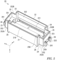
- the stationary housing 20 as shown in Figure 5 , includes side walls 21, 22 and partial walls 23, 24 enclosing the plurality of first contacts 10 and arranged on the first mounting face 61A, extended walls 25 so formed on opposite sides of the stationary housing 20 in the first direction x as to protrude outward in the first direction x from the partial walls 23, 24, joining member retaining portions 26 retaining the housing joining members 15, positioning bosses 27 inserted into holes, not shown, formed in the first circuit board, and legs 28 arranged on the first mounting face 61A. It should be noted that the bosses 27 are not shown in some of the drawings.
- the side walls 21, 22 extend in the first direction x in which the first contacts 10 are arranged, and face each other in the second direction y.
- the partial walls 23, 24 perpendicular to the side walls 21, 22 are arranged on opposite sides in the second direction y between the side walls 21, 22, and are continuous with the extended walls 25.
- a space which has a rectangular shape as seen in a plan view and in which the first contacts 10 are arranged is formed inside the walls 21 to 24.
- the legs 28 are formed at lower ends of four corners between the walls 21 to 24.
- the side walls 21, 22 and the partial walls 23, 24 rise relative to the mounting face 61A from their respective lower ends (for example, 21A) to their respective upper ends (for example, 21B) slightly above the first contacts 10.
- Gaps G ( Figure 1(b) ) are formed between the lower ends of the walls 21 to 24 and the first mounting face 61A.
- Retaining grooves 211 into which the first contacts 10 of the first row R1 are press-fitted are formed with the same pitch as the first contacts 10 near the lower end inside the side wall 21.
- retaining grooves 221 into which the first contacts 10 of the second row R2 are press-fitted are formed with the same pitch as the first contacts 10 near the lower end inside the side wall 22.
- a chamfered portion 212 is formed above the retaining grooves 211 inside the side wall 21 in order to avoid interference between the first contacts 10 and the stationary housing 20.
- the chamfered portion 212 is formed from a position above the retaining grooves 221 to a position near the upper end 21B of the side wall 21.
- the chamfered portion 212 is so inclined relative to the mating direction z as to become farther from a first section 101 of the first contact 10 in the second direction y as it approaches a first curved portion C1 from a stationary retaining portion 10B.
- a chamfered portion 222 similar to the chamfered portion 212 is formed inside the side wall 22.
- the extended wall 25 is formed in a rectangular shape as seen in a plan view by a wall rising in the mating direction z from a lower end 25A to an upper end 25B.
- the upper end 25B is lower than the upper end 21B of the side wall 21 and an upper end 31B of the movable housing 30.
- the extended walls 25, on the opposite sides of the stationary housing 20 in the first direction x, contribute to assembling the stationary housing 20 and the movable housing together while receiving respective portions of the movable housing 30 and the second connector 4 therein.
- the extended wall 25 sets gaps between the stationary housing 20 and the movable housing 30, thereby setting floating ranges. It is preferred that the extended walls 25 be symmetrically formed in the first direction x with the walls 21 to 24 therebetween.
- a facing portion 251 so arranged as to face the first mounting face 61A is formed on the extended wall 25 inside the stationary housing 20.
- the facing portion 251 sets a first gap G1 in the first direction x between the stationary housing 20 and the movable housing 30.
- the facing portion 251 is formed in a plate-like shape extending in the first direction x and in the second direction y, and is supported by the wall of the extended wall 25.
- the facing portion 251 of the present embodiment is so formed as to be substantially C-shaped as seen in a plan view, as will be understood from Figure 5 .
- a predetermined dimension x1 is given between the facing portion 251 at one end in the first direction x and the facing portion 251 at the other end.
- the housing 50 of the second connector 4 is arranged above the facing portions 251 inside the extended walls 25.
- a side below the facing portion 251 of the extended wall 25 is equivalent to a lower region 252 ( Figure 5 ) in which a second gap G2 in the second direction y is set between the stationary housing 20 and the movable housing 30.
- the lower region 252 includes side walls 252A, 252B extending in the first direction x and in the mating direction z below the facing portion 251.
- the joining member retaining portions 26 are provided at the extended walls 25 on the opposite sides of the stationary housing 20 in the first direction x, and retain the housing joining members 15 shown in Figure 3 .
- the housing joining member 15 includes a joining portion 151 joined with solder, not shown, to the first circuit board 61, and a press-fit portion 152 having protrusions 152A on opposite sides.
- a pair of grooves 261 retaining the housing joining member 15 press-fitted from above are formed in the joining member retaining portion 26 along the mating direction z.
- An opening 253 is formed in the extended wall 25 below the facing portion 251 and between the pair of grooves 261. It should be noted that the opening 253 may not be formed in the extended wall 25.
- the stationary housing 20, as shown in Figures 2(b) and 3 includes the two pin-like bosses 27.
- the two bosses 27 protrude in the mating direction z from the lower ends of the side walls 21, 22 or of the partial walls 23, 24, and are spaced from each other in both the first direction x and the second direction y. These bosses 27 have different diameters. Therefore, the first connector 1 can be attached to the first circuit board 61 in a correct orientation that enables the two bosses 27 to be inserted into the holes of the first circuit board 61.
- the movable housing 30 as shown in Figures 2(a), 2(b) and 6(a) , divides the inside of the stationary housing 20 into the first row R1 side and the second row R2 side, and retains the first contacts 10 of the first row R1 and the contacts 10 of the second row R2 with the stationary housing 20.
- the movable housing 30 includes a retaining region 31 extending in the first direction x with a length commensurate with the lengths of the rows R1, R2, and retaining the first contacts 10, and extended regions 32 continuous with opposite sides of the retaining region 31 in the first direction x and involved in positioning relative to the second connector 4, assembling with the stationary housing 20, and setting of the floating ranges.
- the retaining region 31 is given a width (a dimension in the second direction y) and a height (a dimension in the mating direction z) required for retaining the first contacts 10 of the first row R1 and the first contacts 10 of the second row R2.
- a plurality of grooves 310 in each of which the first contact 10 is arranged are formed along the mating direction z in a side face 311 on the first row R1 side of the retaining region 31 and in a side face 312 on the second row R2 side.
- Guide slopes 31C for positioning the movable housing 30 relative to the second contacts 40 of the second connector 4 in the second direction y are formed on the first row R1 side and the second row R2 side in an upper end 31B of the retaining region 31.
- the groove 310 includes a retaining groove 310A into which the first contact 10 is press-fitted, and the groove 310 as a whole is continuous across entire heights of the sides faces 311, 312.
- the grooves 310 are arranged in the first direction x with a constant pitch.
- the depth (a dimension in the second direction y) of the groove 310, as shown in Figure 2(b) varies in the mating direction z.
- the retaining grooves 310A are formed in the vicinity of a lower end 33 of the retaining region 31. The lower end 33 faces the first mounting face 61A.
- a ground retaining groove 31D ( Figure 2(b) ) into which the ground contact connecting member 70 is press-fitted is formed in the lower end 33 of the retaining region 31.
- the extended region 32 includes an upper portion 320 formed with a guide protrusion 321 arranged above the upper ends 31B of the side faces 311, 312, and a lower portion 322 arranged below the facing portion 251 of the stationary housing 20. It is preferred that the extended regions 32 be symmetrically formed in the first direction x with the retaining region 31 therebetween.
- a recess 323 recessed in the first direction x in a position corresponding to the facing portion 251 is formed in the extended region 32.
- the upper portion 320 and the lower portion 322 are divided by the recess 323.
- An inner dimension in the mating direction z of the recess 323 is equal to or larger than the thickness of the facing portion 251.
- the facing portion 251 is inserted into the recess 323.
- the facing portion 251 can be received in the recess 323 until an end face 251A of the facing portion 251 abuts against a back face 323A of the recess 323.
- the guide protrusions 321 come into contact with the housing 50 before the guide slopes 31C come into contact with the housing 50 or the second contacts 40 of the second connector 4, and follow the position of the housing 50 to guide the movable housing 30 in the first direction x and in the second direction y.
- a slope 321A inclined relative to a y-z plane and slopes 321B inclined relative to an x-z plane are formed on the guide protrusion 321.
- a guide range y1 is set within which the movable housing 30 is displaceable in the second direction y under guidance by the slope 321B.
- the guide range y1 is wider than a guide range y2 within which the movable housing 30 is displaceable in the second direction y under guidance by the guide slope 31C.
- a guide range x3 is set within which the movable housing 30 is displaceable in the first direction x under guidance by the slope 321A.
- a dimension x0 ( Figure 6(a) ) in the first direction x of the upper portion 320 is smaller than the dimension x1 ( Figure 5 ) between the facing portions 251 on the opposite sides.
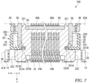
- a dimension x2 ( Figure 6(a) ) in the first direction x of the lower portion 322 is larger than the dimension x1 ( Figure 5 ) between the facing portions 251 on the opposite sides. Therefore, as shown in Figure 7 , the movable housing 30 can be inserted into the stationary housing 20 from below until the lower portions 322 are abutted against lower faces 251B of the facing portions 251.
- the upper portions 320 at this time are accommodated into the stationary housing 20 to a position above the facing portions 251.
- the upper portions 320 are mated with the housing 50 of the second connector 4.
- the housing 50, inside the stationary housing 20, is so arranged as to enclose the upper portions 320.
- the movable housing 30 is so assembled with the stationary housing 20 and the first circuit board 61 as not to be disengaged upward or downward.
- the first connector 1 is not required to include a metal fastener or the like for assembling the movable housing 30, the stationary housing 20, and the first circuit board 61 together, and the movable housing 30 and the stationary housing 20 are not restrained by such a metal fastener or the like.
- the first gap G1 having a predetermined dimension is set between the end face 251A of the facing portion 251 and the back face 323A of the recess 323.
- Figure 7 shows the stationary housing 20 and the movable housing 30 having their respective centers in the first direction x coincidence with each other. From this state, a relative displacement in the first direction x of the movable housing 30 to the right side or the left side of Figure 7 relative to the stationary housing 20 is allowed by up to the dimension of the first gap G1. For example, if the first gap G1 is 1mm, the first connector 1 is given a floating range of ⁇ 1 mm in the first direction x.
- the second gaps G2 are each set between the side wall 322A of the lower portion 322 and an inner face of the side wall 252A of the lower region 252, and between the side wall 322B of the lower portion 322 and an inner face of the side wall 252B of the lower region 252.
- Figure 8 shows the stationary housing 20 and the movable housing 30 having their respective centers in the second direction y coincidence with each other. From this state, a relative displacement in the second direction y of the movable housing 30 to the upper side or the lower side of Figure 8 relative to the stationary housing 20 is allowed by up to the dimension of the second gap G2. For example, if the second gap G2 is 1mm, the first connector 1 is given a floating range of ⁇ 1 mm in the second direction y.
- the movable housing 30 and the stationary housing 20 are capable of relative displacement in the first direction x and in the second direction y, the movable housing 30 also has a positional degree of freedom in a direction of rotation in an x-y plane relative to the stationary housing 20.
- the first connector 1 is given a floating range of a predetermined angle in the direction of rotation in the x-y plane.
- the floating ranges commensurate with the sufficiently large gaps G1, G2 can be achieved within the limit of a maximum amount of elastic deformation of the first contact 10.
- First Contact - A configuration of the first contact 10 shown Figures 9(a) to 9(c), including its shape and functions of its portions, will be described. Figures 9(a) to 9(c) show the first contact 10 unloaded.
- the first contact 10 includes a joining portion 10A joined with solder to the first mounting face 61A, a stationary retaining portion 10B press-fitted into and retained by the stationary housing 20, a movable retaining portion 10C press-fitted into and retained by the movable housing 30, and a connecting portion 10E brought into contact with the second contact 40, and is given a curved shape that allows elastic deformation in the first direction x and in the second direction y.
- the joining portion 10A arranged in parallel with the first mounting face 61A and the stationary retaining portion 10B form an L-shape as seen in a side view.
- the first curved portion C1 and a second curved portion C2 are formed between the stationary retaining portion 10B and the movable retaining portion 10C.
- the first curved portion C1, which is a top of the first contact 10, is inverted U-shaped as seen in the side view.
- the second curved portion C2 is substantially V-shaped as seen in the side view.
- a lower end of the second curved portion C2 is located above the joining portion 10A.
- the connecting portion 10E is substantially C-shaped as seen in the side view. An upper end of the connecting portion 10E is located below an upper end of the first curved portion C1. When it comes to its overall approximate shape, the first contact 10 is formed to be substantially N-shaped.
- the first contact 10 is formed by stamping a sheet material formed from a metal material such as a copper allow into a linear elongated shape, and further forming it. All the floating ranges in the first direction x, in the second direction y, and in the direction of rotation in the x-y plane are set within an elastic range of the first contact 10. Therefore, in order to increase the floating ranges, it is preferred that, among copper alloys, a material having a good spring property be used as a material of the first contact 10.
- the first contact 10 is given a constant thickness across most of its length.
- a thickness t of the first contact 10 is determined to be, for example, within a range of 0.1 to 0.5 mm.
- the thickness of the connecting portion 10E is smaller than the thicknesses of the other portions.
- a width w of the first contact 10 is determined to be at least equal to or more than the thickness t, for example, within a range of 0.1 to 0.5 mm.
- the width w of the first contact 10 varies in a length direction of the first contact 10. For example, in an entire length of the first contact 10 from the joining portion 10A to the connecting portion 10E, the widths of the joining portion 10A and the connecting portion 10E are narrowest so that they will easily deflect in order to increase followability to the first mounting face 61A and the second contact 40.
- a region of the first contact 10 above the movable retaining portion 10C is given a width narrower than the width of the movable retaining portion 10C. This region is smoothly inserted into the retaining groove 310A of the movable housing 30 from below.
- the first contacts 10 are arranged with a constant pitch P greater than a maximum width w set at the first curved portion C1 and at the second curved portion C2 and with a gap g between the adjacent first contacts 10.
- the pitch P is, for example, 0.3 to 0.5 mm, and the first contacts 10 are densely arranged. It is preferred that the gap g be 0.15 mm or more.
- All the first contacts 10 are arranged in parallel with the x-z plane.
- the first contacts 10 of the first row R1 and the first contacts 10 of the second row R2 are arranged with line symmetry with respect to an axis parallel with the mating direction z.
- the first contact 10 includes the first section 101, a second section 102, and a third section 103.
- the first section 101 extends from the stationary retaining portion 10B to the first curved portion C1 toward the side opposite to the first mounting face 61A (the upper side).
- the second section 102 extends from the first curved portion C1, which is so curved as to project upward, toward the first mounting face 61A, and is continuous with the movable retaining portion 10C via the second curved portion C2.
- the third section 103 extends from the movable retaining portion 10C to the connecting portion 10E, which is connected to the second contact 40, toward the side opposite to the first mounting face 61A.
- a first bent portion B1 formed in a shape projecting toward the second section 102 is formed in the first section 101.
- a second bent portion B2 formed in a shape projecting toward the first section 101 is formed in the second section 102 in a position farther from the first mounting face 61A than the position of the first bent portion B 1 in the mating direction z.
- the stationary retaining portion 10B includes two press-fit protrusions 10B1 formed at two vertical stages on widthwise (equivalent to the first direction x) opposite sides, and a protrusion 10B2 formed on one widthwise side.
- a pressing portion 10B3 pressed by a jig, not shown, during press-fitting of the stationary retaining portion 10B is formed perpendicularly to a center line L on a rear side (a lower side) of the protrusion 10B2 in a press-fitting direction,.
- the movable retaining portion 10C includes press-fit protrusions 10C1, a positioning protrusion 10C2, and a pressing portion 10C3 which are similar to the press-fit protrusions 10B1, the protrusion 10B2, and the pressing portion 10B3 of the stationary retaining portion 10B.
- a protrusion dimension of the positioning protrusion 10C2 in the first direction x from the widthwise center line L of the first contact 10 is larger than a protrusion dimension of the press-fit protrusion 10C1 in the first direction x from the center line L.
- the ground contact connecting member 70 will be described.
- Some of the first contacts 10 constituting the first row R1 correspond to a signal potential of an electronic circuit including the first circuit board 61 and the second circuit board 62, and the others correspond to a ground potential of the electronic circuit.
- some of the first contacts 10 constituting the second row R2 correspond to the signal potential of the electronic circuit, and the others correspond to the ground potential of the electronic circuit.
- Signal-use/ground-use allocation of the first contacts 10 is appropriately designed. The signal-use/ground-use allocation has various patterns according to products.
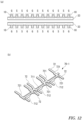
- Figure 12(a) shows an example of the signal-use/ground-use allocation pattern.
- "S” indicates a signal-use contact
- “G” indicates a ground-use contact.
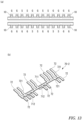
- Figure 13(a) shows another example of the signal-use/ground-use allocation pattern.
- the arrangement of "S” and “G” of the first row R1 of Figure 12(a) and the arrangement of "S” and “G” of the first row R1 of Figure 13(a) are different.
- the arrangement of "S” and “G” of the second row R2 of Figure 12(a) and the arrangement of "S" and “G” of the second row R2 of Figure 13(a) are different.
- the ground contact connecting member 70 contacts only a ground contact group GG composed of the plurality of first contacts 10 allocated to a ground use among all the first ground contacts 10. All the first contacts 10 in contact with the ground contact connecting member 70 become equipotential.
- the reference signs GG are separately shown at four locations.
- GG only some of the first contacts 10 of the ground contact group GG are denoted by GG.
- the ground contact group GG is equivalent to a group of the first contacts 10 corresponding to the ground potential of the whole ground contact connecting member 70, and the ground contact group GG is equivalent to some of the first contacts 10 of the first row R1 and some of the first contacts 10 of the second row R2.
- the ground contact connecting member 70 includes a support portion 71 provided at the lower end 33 (an installation portion) of the movable housing 30 and extending in the first direction x, and a plurality of contacting beams 72 contacting the ground contact group GG from the first mounting face 61 side. Each contacting beam 72 extends from the support portion 71 toward the first row R1 or toward the second row R2. Each contacting beam 72 is arranged between the lower end 33 and the first mounting face 61A.
- the support portion 71 includes a link portion 711 extending elongatedly in the first direction x along the lower end 33, and a retaining portion 712 provided at the link portion 711 and retained at the lower end 33.
- the link portion 711 links fixed ends 72A of the contacting beams 72 together in the first direction x and in the second direction y.
- Press-fit protrusions 712A are formed on opposite sides in the first direction x of the retaining portion 712.
- the link portion 711 of the present embodiment is provided with a plurality of the retaining portions 712. These retaining portions 712 are press-fitted into the respective ground retaining grooves 31D of the movable housing 30.
- the ground contact connecting member 70 can be formed by stamping and forming a sheet metal material such as a copper alloy. It is preferred that the retaining portion 712 be a bent piece bent perpendicularly on one widthwise (the second direction y) side of the link portion 711. The retaining portion 712 is press-fitted into the lower end 33 in the mating direction z. The retaining portion 712 can be formed anywhere in the first direction x other than where the contacting beams 72 are formed on widthwise opposite sides of the link portion 711 (for example, x4 of Figure 4 ).
- the contacting beams 72 protrude perpendicularly from the link portion 711 in the second direction y toward the ground-use contacts 10 of the first row R1 or toward the ground-use contacts 10 of the second row R2.
- the length of the contacting beam 72 extending from the link portion 711 toward the first row R1 and the length of the contacting beam 72 extending from the link portion 711 toward the second row R2 are different, but they may be the same.
- the ground contact connecting member 70 of the present embodiment as shown in Figure 10(b) , is formed with line symmetry in the second direction y with respect to the retaining portion 712.
- the width (a dimension in the first direction x) of the contacting beam 72 is narrower than the width (a dimension in the first direction x) of a portion contacting the contacting beam 72 of the first contact 10.
- the width of the contacting beam 72 may be equal to the joining portion 10A and/or the connecting portion 10E of the first contact 10.
- the lower end 33 of the movable housing, at which the ground contact connecting member 70 is installed, is located above the lower end of the second curved portion C2 of the first contact 10.
- the second curved portion C2 of the first contact 10 is adjacent to the lower end 22.
- the second curved portion C2 of the first contact 10 is located in the vicinity of the movable retaining portion 10C retained by the movable housing 30, the second curved portion C2 is displaced following the movable housing 30. Therefore, even when the movable housing 30 is displaced relative to the stationary housing 20 and the housing 50 of the second connector 4 while the first curved portion C1 of the first contact 10 is being elastically deformed during mating of the first connector 1 and the second connector 4, a distance between the second curved portion C2 and the movable housing 30 remains almost unchanged. Therefore, the fact that the contact beam 72 is in contact with the second curved portion C2 has no effect on displacement behavior of the movable housing 30 relative to the stationary housing within the floating ranges.
- the contacting beam 72 of the present embodiment extends in the same plane as the link portion 711, and is formed in a flat shape.
- the contacting beam 72 is not limited to this, and may have a step 721 in the thickness direction, like the contacting beam 72 included in ground contact connecting members 70-1, 70-2 shown in Figures 12(b) and 13(b) .
- the step 721 causes the position of a free end 72B of the contact beam 72 to be spaced farther from the first mounting face 61A than the position of the fixed end 72A.
- the contacting beam 72 can be given an appropriate shape according to a relative distance between the lower end 33, the second curved portion C2, and the contacting beam 72, a contact pressure required between the contact beam 72 and the second curved portion C2, or the like.
- the signal-use/ground-use allocation has various patterns according to products.
- the ground contact connecting member 70-1 shown in Figure 12(b) corresponds to the allocation pattern shown in Figure 12(a) .
- the ground contact connecting member 70-1 shown in Figure 13(b) corresponds to the allocation pattern shown in Figure 13(a) .
- the first connector 1 of the present embodiment includes means for making the ground-use first contacts 10 equipotential as the ground contact connecting member 70 separate from the first contacts 10. Therefore, the ground contact connecting member 70 can be adapted to various products by customizing the positions of the contacting beams 72 and the retaining portion 712 according to the signal-use/ground-use allocation pattern.
- a portion corresponding to the ground retaining groove 31D of a mold for molding the movable housing 30 be an insert so that the movable housing 30 having the ground retaining groove 31D in a different position can be produced.
- ground contact connecting member 70 can improve SI (signal intensity) performance, for example, as shown in an analysis result of the frequency response of the insertion loss (IL) of Figure 14 .
- the second connector 4 includes the plurality of second contacts 40, the housing 50 retaining them, and joining members 45, and is mated with the movable housing 30.
- the second contacts 40 of the first row r1 and the second contacts 40 of the second row r2, like the first contacts 10, are arranged with a constant pitch P in the first direction x, and are adjacent to each other in the second direction y.
- the second contact 40 is formed by stamping a sheet material formed from a metal material such as a copper allow into a linear elongated shape, and further forming it.
- the second contact 40 includes a joining portion 40A joined to the second circuit board 62, a retaining portion 40B retained by the housing 50, and a connecting portion 40C electrically connected to the first contact 10.
- the second contact 40 of the present embodiment has a section 401 extending perpendicularly to the joining portion 40A, and is formed in an L-shape as a whole.
- the section 401 includes the retaining portion 40B and the connecting portion 40C.
- the retaining portion 40B includes press-fit protrusions 40B 1 and a protrusion 40B2, and is formed in the vicinity of the joining portion 40A in the section 401.
- a region below the retaining portion 40B in the section 401 is equivalent to the connecting portion 40C.
- the connecting portion 10E of the first contact 10 of the first row R1 and the connecting portion 10E of the first contact 10 of the second row R2 are inserted into between the connecting portion 40C of the first row r1 and the connecting portion 40C of the second row r2, as shown in Figure 1(b) .
- the housing 50 includes walls 51 to 54 enclosing the second contacts 40 of the first row r1 and of the second row r2 from four directions and arranged on the second mounting face 62A, two positioning bosses 57 ( Figure 1(a) ) inserted into holes, not shown, of the second circuit board 62, and legs 58 arranged on the second mounting face 62A.
- the side wall 51 and the side wall 52 extend in the first direction x with a length commensurate with the lengths of the rows r1, r2, and face each other in the second direction y.
- Grooves 511 in each of which the second contact 40 of the first row r1 is arranged are formed inside the side wall 51 along the mating direction z.
- the groove 511 includes a retaining groove 511A into which the second contact 40 is press-fitted.
- Grooves 521 in each of which the second contact 40 of the second row r2 is arranged and each of which includes a retaining groove 521A are also formed inside the side wall 52 along the mating direction z.
- a guide slope 512 is formed on an inner side of a lower end of the side wall 51 in order to position the movable housing 30 of the first connector 1 and the housing 50 relative to each other in the second direction y.
- a similar guide slope 522 is also formed on an inner side of a lower end of the side wall 52. The guide slopes 512, 522 are symmetrically formed in the second direction y.
- a distance d1 in the second direction y between the connecting portion 40C of the second contact 40 of the first row r1 and the connecting portion 40C of the second contact 40 of the second row r2 is smaller than a distance d2 ( Figure 2(b) ) in the second direction y between a vertex of the connecting portion 10E of the first contact 10 of the first row R1 and a vertex of the connecting portion 10E of the first contact 10 of the second row R2.
- the connecting portion 10E of the first contact 10 of the first row R1 contacts the connecting portion 40C of the second contact 40 at the vertex while being pressed between the second contact 40 of the first row r1 and the movable housing 30.
- the walls 53, 54 are provided at opposite ends in the first direction x of the side walls 51, 52, and face each other in the first direction x. Heights of the walls 53, 54 from the second mounting face 62A are higher than heights of the side walls 51, 52 from the second mounting face 62A.
- First guide slopes 55 inclined relative to a y-z plane are formed on opposite ends in the first direction x of the walls 51 to 54.
- Second guide slopes 59 inclined relative to an x-z plane are formed at four corners of the walls 51 to 54. These guide slopes 55, 59 are arranged below the lower ends 51A, 52A of the side walls 51, 52.
- the first guide slopes 55 are symmetrically formed in the first direction x.
- the second guide slopes 59 are symmetrically formed in the second direction y.
- the first guide slopes 55 contact the slopes 321A of the guide protrusions 321 of the movable housing 30 before the guide slopes 512, 522 of the side walls 51, 52 contact the guide slopes 31C of the movable housing 30, and follow the position of the housing 50 to guide the movable housing 30 in the first direction x.
- the second guide slopes 59 contact the slopes 321B of the guide protrusions 321 of the movable housing 30 before the guide slopes 512, 522 of the side walls 51, 52 contact the guide slopes 31C of the movable housing 30, and follow the position of the housing 50 to guide the movable housing 30 in the second direction y.
- the first guide slopes 55 are inclined relative to the y-z plane.
- the second guide slopes 59 are inclined relative to the x-z plane.
- a guide range x3 ( Figure 15(a) ) equal to the slope 321A of the guide protrusion 321 of the movable housing 30 is set in the first guide slope 55A. It is preferred that the guide range x3 be larger than the dimension of the first gap G1.
- a guide range y1 ( Figure 15(b) ) equal to the slope 321B of the guide protrusion 321 of the movable housing 30 is set in the second guide slope 59A. It is preferred that the guide range y1 be larger than the dimension of the second gap G2.
- the joining member 45 includes a joining portion 451 joined to the second circuit board 62, and a press-fit portion having protrusions 452A on opposite sides.
- Joining member retaining portions 56 are provided on outer sides of the walls 53, 54.
- a retaining groove 56A into which the joining member 45 is inserted from below is formed in the joining member retaining portion 56.
- FIG. 1 A procedure for assembling the connector assembly 100 will be described below, and simultaneously main advantageous effects provided by the present embodiment will also be described.
- FIG. 1 An example of a procedure for assembling the first connector 1 will be described.
- the housing joining members 15 are press-fitted into respective ones of the pair of grooves 261 provided in the respective extended walls 25 on the opposite sides of the stationary housing 20 ( Figure 2(a) ).
- the movable housing 30 is arranged inside the stationary housing 20 from below ( Figures 2(b) , 7 ).
- the plurality of first contacts 10 can be attached to the stationary housing 20 and to the movable housing 30 from below using a jig, not shown.
- a jig not shown
- the stationary housing 20 and the movable housing 30 are being supported in position by a first jig, not shown, and the first contacts 10 are also being aligned in the first row R1 and in the second row R2 by a second jig
- the first contacts 10 of the first row R1 and of the second row R2 are pushed upward by a third jig in contact with the pressing portions 10B3 and by the third jig in contact with the pressing portions 10C3.
- the stationary retaining portions 10B of the first contacts 10 of the second row R2 are press-fitted into the retaining grooves 221 of the stationary housing 20, and the movable retaining portions 10C of the first contacts 10 of the second row R2 are also press-fitted into the retaining grooves 310A on the second row R2 side of the movable housing 30.
- the movable housing 30 When the stationary retaining portions 10B and the movable retaining portions 10C are press-fitted, the movable housing 30 is supported by the second curved portions C2 of the first contacts 10 of the first row R1 and the second curved portions C2 of the first contacts 10 of the second row R2. At this time, the lower end 33 of the movable housing 30 is located above the legs 28 of the stationary housing 30.
- the second curved portions C2 are located below the lower end 33 of the movable housing 30, and are located above the legs 28.
- the joining portions 10A of the first contacts 10 are located slightly below the legs 28 of the stationary housing 20.
- the ground contact connecting member 70 is attached to the movable housing 30 by press-fitting the retaining portion 712 into the ground retaining groove 31D.
- each contacting beam 72 is deflected in the thickness direction and pressed in the mating direction z against the second curved portion C2 of the ground-use first contact 10. Therefore, even when the respective positions of the second curved portions C2 of the first contacts 10 vary in the mating direction z, the contacting beams 72 can be brought into stable contact with the contact group GG. In this manner, the SI performance can be stabilized through potential equalization of the ground-use contacts 10 by the member 70 including the contacting beams 72 brought into stable contact with the first contacts 10.
- the movable housing 30 is supported with a positional degree of freedom within the floating ranges in the first direction x, in the second direction y, and in the direction of rotation in the x-y plane by elastic deformation of the first contacts 10 of the first row R1 and of the first contacts 10 of the second row R2.
- the second contacts 40 are inserted into the grooves 511, 521 from above while being arranged in the first row R1 and in the second row R2, respectively, using a jig, not shown, and the second contacts 40 are press-fitted into the retaining grooves 511A, 521A.
- the joining members 45 are press-fitted into the joining member retaining portions 56. In this manner, assembling of the second connector 4 is completed.
- the bosses 57 of the housing 50 are inserted into the holes, not shown, of the second circuit board 62, and the legs 58 are brought into contact with the second mounting face 62A.
- the joining portion 40A of each second contact 40 is joined with solder to the second mounting face 62A, and the joining portions 451 of the joining members 45 are joined with solder to the second mounting face 62A.
- the movable housing 30 When the movable housing 30, the stationary housing 20, and the first circuit board 61 are in an assembled state, the movable housing 30 is supported by the stationary housing 20 via the first contacts 10. In other words, the movable housing 30 is so supported as to be displaceable by elastic deformation of the first contacts 10 in the first direction x and in the second direction y.
- the lower portions 322 of the movable housing 30 and the facing portions 251 of the stationary housing 20 face each other in the mating direction z, and relative displacement in the first direction x and in the second direction y between the movable housing 30 including the lower portions 322 and the stationary housing 20 including the facing portions 251 is allowed within the floating ranges commensurate with the gaps G1, G2 set between the movable housing 30 and the stationary housing 20.
- the first connector 1 and the connector assembly 100 which can increase the floating ranges, for example, to a scale of ⁇ 1 mm or more can be provided.
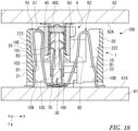
- the movable housing 30 follows the position of the housing 50, and is displaced in the second direction y relative to the stationary housing 20 while elastically deforming the first contacts 10 in the second direction y, as shown in Figure 18 . Since the ground contact connecting member 70 in contact with the first contacts 10 has no effect on behavior of the movable housing 30, as described above, the installation of the ground contact connecting member 70 does not change the floating ranges.
- the first connector 1 and the second connector 4 are allowed to have a misalignment amount commensurate with the predetermined floating ranges in the first direction x, the second direction y, and the direction of x-y rotation based on the first gap G1 and the second gap G2.
- the movable housing 30 is guided in the second direction y by an interaction between the slopes 321B of the guide protrusions 321 and the second guide slopes 59 of the housing 50 to determine an approximate position in the second direction y, and is thereafter positioned in the second direction y relative to the housing 50 by an interaction between the guide slopes 31C and the guide slopes 512, 522. Therefore, the movable housing 30 and the housing 50 can be smoothly mated.
- Figure 19 shows the first connector 1 and the second connector 4 misaligned in both the first direction x and the second direction y.
- the movable housing 30 is displaced relative to the stationary housing 20 and the housing 50 by an interaction between the slopes 321A, 321B of the guide protrusions 321 and the guide slopes 55, 59 and a subsequent interaction between the guide slopes 31C and the guide slopes 512, 522.
- each first contact 10 is elastically deformed in the first direction x and in the second direction y.
- a joining object to which the first contact 10 is joined is not necessarily limited to a circuit board.
- an object to which the second contact 40 is joined is not necessarily limited to a circuit board.
- the facing portion 251 formed on the stationary housing 20, and a portion of the movable housing 30 arranged between the facing portion 251 and a reference plane to be joined are not limited to the above embodiment, and may be appropriately configured.
- first gap G1 is not limited to being set between the facing portion 251 and the recess 323, as in the above embodiment, and may be set between the movable housing 30 and the stationary housing 20 in a position at a distance from the facing portion 251 and the recess 323.
- second gaps G2 are not limited to being set between the side walls 322A, 322B of the extended region 32 and the side walls 252A, 252B of the extended wall 25, as in the above embodiment, and may be set between the movable housing 30 and the stationary housing 20 in a position at a distance from the extended region 32 and the extended wall 25.
- a ground contact connecting member contacting a ground contact group equivalent to, among a plurality of contacts arranged along a predetermined first direction in a first row and in a second row in parallel, some of the contacts of the first row and some of the contacts of the second row adjacent to the first row in a second direction, the ground contact connecting member including: a support portion provided along the first direction at an installation portion of a connector housing retaining the contacts; and a plurality of contacting beams extending from the support portion toward the first row or toward the second row and contacting the ground contact group, wherein the contacting beams are pressed against the contacts of the ground contact group in a third direction crossing both the first direction and the second direction.
- the support portion includes a link portion linking fixed ends of the contacting beams in the first direction and in the second direction, and at least one press-fit portion provided at the link portion and press-fitted into the installation portion in the third direction.
- the ground contact connecting member according to paragraph [101], wherein the contact includes a movable retaining portion retained by the connector housing, and a stationary retaining portion retained by a stationary housing separate from the connector housing, a first curved portion and a second curved portion are formed between the stationary retaining portion and the movable retaining portion, and the contacting beam contacts the second curved portion of the contact constituting the ground contact group in a vicinity of the movable retaining portion.
- a connector including: the ground contact connecting member according to any one of paragraphs [101] to [104]; the plurality of contacts; the connector housing; a stationary housing retaining the contacts with the connector housing and supporting the connector housing via the contacts.
- a connector assembly including: a first connector as the connector according to any one of paragraphs [101] to [106]; and a second connector mated with the connector housing of the first connector.
Landscapes
- Details Of Connecting Devices For Male And Female Coupling (AREA)
- Coupling Device And Connection With Printed Circuit (AREA)
Abstract
Description
- The present invention relates to means for making a contact group equipotential, a connector including the means, and a connector assembly including the connector.
- A so-called floating connector assembly can be used for a mechanical connection and an electrical connection between components included in various electronics. Such a connector assembly includes a first connector including a contact joined to a first circuit board, and a second connector including a contact j oined to a second circuit board, as described, for example, in
CN 113346285 . In order to avoid a trouble in assembling the first connector and the second connector with the first circuit board and the second circuit board due to dimensional and form, machining, and/or assembly tolerances, the first connector and the second connector are configured to be mateable even when they are misaligned relative to each other within a predetermined floating range, by allowing elastic deformation of the contacts, which are formed in a predetermined shape. - A socket connector described in
CN 113346285 includes a lower shell, an upper shell inserted into the lower shell from above, and a plurality of socket contacts retained by the lower shell and the upper shell, and is mated with a plug connector. Each socket contact is formed in a shape having a plurality of bends, and is retained by the lower shell and the upper shell. The upper shell is assembled with the lower shell by engagement with a metal fitting. The metal fitting is joined to the circuit board in order to reinforce joint between the socket contacts and the circuit board. - The socket connector described in
CN 113346285 includes an electrical conductor in contact with some of the plurality of contacts. This electrical conductor makes the contacts in contact therewith equipotential. The electrical conductor is an elongated member having a rectangular cross-sectional shape, and has a plurality of protrusions formed at equal intervals on opposite side faces. When this electrical conductor is accommodated in a lower end portion of the upper shell, the protrusions are exposed through grooves formed in the upper shell, and brought into contact with the respective contacts. - Patent literature includes
Chinese Patent Publication No. 113346285 (CN 113346285 ) - The structure described in
CN 113346285 requires strict management of dimensional and shape, machining, and assembly tolerances in order to ensure that the electrical conductor having the plurality of protrusions formed thereon is assembled with the upper shell and that the protrusions exposed through the grooves of the upper shell are in contact with the contacts. However, with increased structural complexity of electronics, and with increased contact pitch fineness, the tolerance management becomes more difficult, and therefore it is difficult to bring the plurality of protrusions of the electrical conductor into stable contact with the respective contacts. - An object of the present invention is to provide an electrical conducting member capable of stable contact with a plurality of contacts subjected to potential equalization, a connector including the electrical conducting member, and a connector assembly including the connector.
- The present invention is a ground contact connecting member contacting a ground contact group equivalent to, among a plurality of contacts arranged along a predetermined first direction in a first row and in a second row in parallel, some of the contacts of the first row and some of the contacts of the second row adjacent to the first row in a second direction, the ground contact connecting member including a support portion provided along the first direction at an installation portion of a connector housing retaining the contacts, and a plurality of contacting beams extending from the support portion toward the first row or toward the second row and contacting the ground contact group. The contacting beams are pressed against the contacts of the ground contact group in a third direction crossing both the first direction and the second direction.
- A connector of the present invention includes the ground contact connecting member described above, the plurality of contacts, the connector housing, and a stationary housing retaining the contacts with the connector housing and supporting the connector housing via the contacts.
- A connector assembly of the present invention includes a first connector as the connector described above, and a second connector mated with a movable housing of the first connector.
- Since the ground contact group is subjected to potential equalization using the ground contact connecting member, SI (signal intensity) performance can be improved, as also shown in an analysis result described below. When the ground contact connecting member is installed in the connector housing, each contacting beam is deflected and pressed in the third direction against the ground-use contact. Therefore, even when the respective positions of the first contacts vary in the third direction, the contacting beams can be brought into stable contact with the first contacts of the ground contact group. Furthermore, through the potential equalization of the ground-use first contacts by the member including the contacting beams brought into stable contact with the first contacts, the SI performance can be stabilized.
- In addition, by customizing the shape of the ground contact connecting member according to a signal-use/ground-use allocation pattern of the first contacts, the ground contact connecting member can be adapted to various products.
-
-
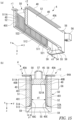
Figure 1(a) is an isometric view showing a connector assembly according to an embodiment of the present embodiment. The connector assembly includes a first connector and a second connector.Figure 1(b) is a cross sectional view along a line Ib-Ib ofFigure 1(a) . -
Figure 2(a) is an isometric view showing the first connector.Figure 2(b) is a cross sectional view along a line IIb-IIb ofFigure 2(a) . -
Figure 3 is an exploded isometric view of the first connector (excluding a ground contact connecting member). -
Figure 4 is an isometric view of the ground contact connecting member. -
Figure 5 is an isometric view showing a stationary housing of the first connector. -
Figure 6(a) is an isometric view showing a movable housing of the first connector.Figure 6(b) is a partial enlarged front view of a guide protrusion.Figure 6(c) is a partial enlarged side view of the guide protrusion. -
Figure 7 is a cross sectional view along a line VII-VII ofFigure 1(a) , the view showing a first gap set between the stationary housing and the movable housing in a first direction. -
Figure 8 is a bottom view shown from a direction of an arrow VIII ofFigure 1(a) , the view showing a second gap set between the stationary housing and the movable housing in a second direction. The ground contact connecting member is not shown. -
Figure 9(a) is a side view of a first contact.Figure 9(b) is an isometric view of the first contact, and Figure 9(c) is a front view of the first contact. -
Figure 10(a) is a bottom view shown from a direction of an arrow Xa ofFigure 1(a) .Figure 10(b) is a front view of the ground contact connecting member shown from a direction of an arrow Xb of (a). -
Figure 11 is a bottom view of the ground contact connecting member and the first contact. -
Figure 12(a) is a schematic view showing an example of a signal-use/ground-use allocation pattern.Figure 12(b) is an isometric view showing the ground contact connecting member including contacting portions so arranged as to correspond to the positions of ground-use contacts ofFigure 12(a) . -
Figure 13(a) is a schematic view showing an example of a signal-use/ground-use allocation pattern different fromFigure 13(a). Figure 13(b) is an isometric view showing the ground contact connecting member including contacting portions so arranged as to correspond to the positions of ground-use contacts ofFigure 13(a) . -
Figure 14 is a graph for illustrating an advantage provided by the ground contact connecting member. -
Figure 15(a) is a partially cutaway isometric view of the second connector.Figure 15(b) is a transverse cross sectional view ofFigure 15(a) . -
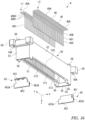
Figure 16 is an exploded isometric view of the second connector. -
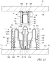
Figure 17 is a cross sectional view showing the first connector and the second connector before mating. -
Figure 18 is a cross sectional view showing the contacts elastically deformed in the first direction when the first connector and the second connector are mated. -
Figure 19 is a top view showing the contacts elastically deformed in the first direction and in the second direction when the first connector and the second connector are mated. - An embodiment of the present invention will be described below with reference to the accompanying drawings. Overall Configuration - A
connector assembly 100 shown inFigures 1(a) and 1(b) includes afirst connector 1 and asecond connector 4 that are mated with each other, and is used for a mechanical connection and an electrical connection between circuit boards included in various electronics. General configurations of thefirst connector 1 and thesecond connector 4 will be first described. Thefirst connector 1 includes a plurality offirst contacts 10, and astationary housing 20 and amovable housing 30 that retain the plurality offirst contacts 10. The plurality offirst contacts 10 are joined to afirst circuit board 61 as an object to be joined. Thefirst contacts 10 are arranged in a first row R1 and in a second row R2 in parallel along a predetermined first direction x, and arranged on a first mountingface 61A of thefirst circuit board 61. - The
second connector 4 includes a plurality ofsecond contacts 40, and ahousing 50 retaining the plurality ofsecond contacts 40. The plurality ofsecond contacts 40 are joined to asecond circuit board 62. Like thefirst contacts 10, thesecond contacts 40 are also arranged in a first row r1 and in a second row r2 in parallel, and arranged on a second mountingface 62A of thesecond circuit board 62. When thefirst connector 1 and the second connector are mated, thefirst contacts 10 of the first row R1 are individually electrically connected to thesecond contacts 40 of the first row r1, and thefirst contacts 10 of the second row R2 are also individually electrically connected to thesecond contacts 40 of the second row r2. - The
first connector 1 and thesecond connector 4 are mated in a mating direction z perpendicular to the first mountingface 61A and to the second mountingface 62A, with thefirst circuit board 61 and thesecond circuit board 62 arranged in parallel with each other. The first mountingface 61A includes the first direction x and a second direction y perpendicular to the first direction x and to the mating direction z. The same applies to the second mountingface 62A. - A side toward the
first circuit board 61 in the mating direction z (a third direction) is referred to herein as a lower side, and a side opposite to thefirst circuit board 61 in the mating direction z as an upper side. - The
first connector 1 of the present embodiment, as will be described below, allows relative displacement between thefirst circuit board 61 and thesecond circuit board 62 within floating ranges corresponding to dimensions of gaps set in the first direction x and the second direction y, respectively, between thestationary housing 20 and themovable housing 30. - Configuration of First Connector - As shown in
Figures 2(a), 2(b) , and3 , thefirst connector 1 includes the plurality offirst contacts 10, thestationary housing 20, and themovable housing 30 so arranged as to be displaceable relative to thestationary housing 20. In addition, it is preferred that thefirst connector 1 includehousing joining members 15 joining thestationary housing 20 to thefirst circuit board 61, and a ground contact connecting member 70 (Figure 4 ) contacting some of thecontacts 10. It should be noted that the groundcontact connecting member 70 is not shown in some of the drawings. - The
first contacts 10 of the first row R1 and thefirst contacts 10 of the second row R2 are each arranged with an equal pitch in the first direction x, and are arranged adjacently in the second direction y. In the present embodiment, thefirst contacts 10 of the first row R1 and thefirst contacts 10 of the second row R2 are so arranged as to have their positions in the first direction x coincident with each other. Thefirst contacts 10 of the first row R1 and thefirst contacts 10 of the second row R2 are not limited to this, and may be so arranged as to be shifted in the first direction x by half the pitch from each other. - The
stationary housing 20 is integrally formed by injection molding using an electrically insulating resin material. The same applies to themovable housing 30. - Stationary Housing - The
stationary housing 20, as shown inFigure 5 , includesside walls partial walls first contacts 10 and arranged on the first mountingface 61A, extendedwalls 25 so formed on opposite sides of thestationary housing 20 in the first direction x as to protrude outward in the first direction x from thepartial walls member retaining portions 26 retaining thehousing joining members 15, positioningbosses 27 inserted into holes, not shown, formed in the first circuit board, andlegs 28 arranged on the first mountingface 61A. It should be noted that thebosses 27 are not shown in some of the drawings. - The
side walls first contacts 10 are arranged, and face each other in the second direction y. Thepartial walls side walls side walls extended walls 25. A space which has a rectangular shape as seen in a plan view and in which thefirst contacts 10 are arranged is formed inside thewalls 21 to 24. Thelegs 28 are formed at lower ends of four corners between thewalls 21 to 24. - The
side walls partial walls face 61A from their respective lower ends (for example, 21A) to their respective upper ends (for example, 21B) slightly above thefirst contacts 10. Gaps G (Figure 1(b) ) are formed between the lower ends of thewalls 21 to 24 and the first mountingface 61A. - Retaining
grooves 211 into which thefirst contacts 10 of the first row R1 are press-fitted are formed with the same pitch as thefirst contacts 10 near the lower end inside theside wall 21. Likewise, retaininggrooves 221 into which thefirst contacts 10 of the second row R2 are press-fitted are formed with the same pitch as thefirst contacts 10 near the lower end inside theside wall 22. - A chamfered
portion 212 is formed above the retaininggrooves 211 inside theside wall 21 in order to avoid interference between thefirst contacts 10 and thestationary housing 20. The chamferedportion 212 is formed from a position above the retaininggrooves 221 to a position near theupper end 21B of theside wall 21. The chamferedportion 212 is so inclined relative to the mating direction z as to become farther from afirst section 101 of thefirst contact 10 in the second direction y as it approaches a first curved portion C1 from astationary retaining portion 10B. A chamferedportion 222 similar to the chamferedportion 212 is formed inside theside wall 22. - The
extended wall 25 is formed in a rectangular shape as seen in a plan view by a wall rising in the mating direction z from alower end 25A to anupper end 25B. Theupper end 25B is lower than theupper end 21B of theside wall 21 and anupper end 31B of themovable housing 30. Theextended walls 25, on the opposite sides of thestationary housing 20 in the first direction x, contribute to assembling thestationary housing 20 and the movable housing together while receiving respective portions of themovable housing 30 and thesecond connector 4 therein. In addition, theextended wall 25 sets gaps between thestationary housing 20 and themovable housing 30, thereby setting floating ranges. It is preferred that theextended walls 25 be symmetrically formed in the first direction x with thewalls 21 to 24 therebetween. - As shown in
Figures 7 and8 , a facingportion 251 so arranged as to face the first mountingface 61A is formed on theextended wall 25 inside thestationary housing 20. The facingportion 251 sets a first gap G1 in the first direction x between thestationary housing 20 and themovable housing 30. The facingportion 251 is formed in a plate-like shape extending in the first direction x and in the second direction y, and is supported by the wall of theextended wall 25. The facingportion 251 of the present embodiment is so formed as to be substantially C-shaped as seen in a plan view, as will be understood fromFigure 5 . A predetermined dimension x1 is given between the facingportion 251 at one end in the first direction x and the facingportion 251 at the other end. - The
housing 50 of thesecond connector 4 is arranged above the facingportions 251 inside theextended walls 25. A side below the facingportion 251 of theextended wall 25 is equivalent to a lower region 252 (Figure 5 ) in which a second gap G2 in the second direction y is set between thestationary housing 20 and themovable housing 30. Thelower region 252 includesside walls portion 251. - The joining
member retaining portions 26 are provided at theextended walls 25 on the opposite sides of thestationary housing 20 in the first direction x, and retain thehousing joining members 15 shown inFigure 3 . Thehousing joining member 15 includes a joining portion 151 joined with solder, not shown, to thefirst circuit board 61, and a press-fit portion 152 havingprotrusions 152A on opposite sides. A pair ofgrooves 261 retaining thehousing joining member 15 press-fitted from above are formed in the joiningmember retaining portion 26 along the mating direction z. - An
opening 253 is formed in theextended wall 25 below the facingportion 251 and between the pair ofgrooves 261. It should be noted that theopening 253 may not be formed in theextended wall 25. - The
stationary housing 20, as shown inFigures 2(b) and3 , includes the two pin-like bosses 27. The twobosses 27 protrude in the mating direction z from the lower ends of theside walls partial walls bosses 27 have different diameters. Therefore, thefirst connector 1 can be attached to thefirst circuit board 61 in a correct orientation that enables the twobosses 27 to be inserted into the holes of thefirst circuit board 61. - Movable Housing - The
movable housing 30, as shown inFigures 2(a), 2(b) and6(a) , divides the inside of thestationary housing 20 into the first row R1 side and the second row R2 side, and retains thefirst contacts 10 of the first row R1 and thecontacts 10 of the second row R2 with thestationary housing 20. Themovable housing 30 includes a retainingregion 31 extending in the first direction x with a length commensurate with the lengths of the rows R1, R2, and retaining thefirst contacts 10, andextended regions 32 continuous with opposite sides of the retainingregion 31 in the first direction x and involved in positioning relative to thesecond connector 4, assembling with thestationary housing 20, and setting of the floating ranges. - The retaining
region 31 is given a width (a dimension in the second direction y) and a height (a dimension in the mating direction z) required for retaining thefirst contacts 10 of the first row R1 and thefirst contacts 10 of the second row R2. A plurality ofgrooves 310 in each of which thefirst contact 10 is arranged are formed along the mating direction z in aside face 311 on the first row R1 side of the retainingregion 31 and in aside face 312 on the second row R2 side. Guide slopes 31C for positioning themovable housing 30 relative to thesecond contacts 40 of thesecond connector 4 in the second direction y are formed on the first row R1 side and the second row R2 side in anupper end 31B of the retainingregion 31. - The
groove 310 includes a retaininggroove 310A into which thefirst contact 10 is press-fitted, and thegroove 310 as a whole is continuous across entire heights of the sides faces 311, 312. Thegrooves 310 are arranged in the first direction x with a constant pitch. The depth (a dimension in the second direction y) of thegroove 310, as shown inFigure 2(b) , varies in the mating direction z. The retaininggrooves 310A are formed in the vicinity of alower end 33 of the retainingregion 31. Thelower end 33 faces the first mountingface 61A. - A
ground retaining groove 31D (Figure 2(b) ) into which the groundcontact connecting member 70 is press-fitted is formed in thelower end 33 of the retainingregion 31. A plurality of theground retaining grooves 31D, which are recessed upward from thelower end 33, are scattered in the first direction x in the retainingregion 32. - The
extended region 32 includes anupper portion 320 formed with aguide protrusion 321 arranged above the upper ends 31B of the side faces 311, 312, and alower portion 322 arranged below the facingportion 251 of thestationary housing 20. It is preferred that theextended regions 32 be symmetrically formed in the first direction x with the retainingregion 31 therebetween. - A
recess 323 recessed in the first direction x in a position corresponding to the facingportion 251 is formed in the extendedregion 32. Theupper portion 320 and thelower portion 322 are divided by therecess 323. An inner dimension in the mating direction z of therecess 323 is equal to or larger than the thickness of the facingportion 251. Depending on relative positions of themovable housing 30 and thestationary housing 20, the facingportion 251 is inserted into therecess 323. The facingportion 251 can be received in therecess 323 until anend face 251A of the facingportion 251 abuts against aback face 323A of therecess 323. - The guide protrusions 321 come into contact with the
housing 50 before the guide slopes 31C come into contact with thehousing 50 or thesecond contacts 40 of thesecond connector 4, and follow the position of thehousing 50 to guide themovable housing 30 in the first direction x and in the second direction y. To this end, aslope 321A inclined relative to a y-z plane and slopes 321B inclined relative to an x-z plane are formed on theguide protrusion 321. - As shown in
Figure 6(b) , for theslope 321B of theguide protrusion 321, a guide range y1 is set within which themovable housing 30 is displaceable in the second direction y under guidance by theslope 321B. The guide range y1 is wider than a guide range y2 within which themovable housing 30 is displaceable in the second direction y under guidance by theguide slope 31C. In addition, as shown inFigure 6(c) , for theslope 321A of theguide protrusion 321, a guide range x3 is set within which themovable housing 30 is displaceable in the first direction x under guidance by theslope 321A. - A dimension x0 (
Figure 6(a) ) in the first direction x of theupper portion 320 is smaller than the dimension x1 (Figure 5 ) between the facingportions 251 on the opposite sides. On the other hand, a dimension x2 (Figure 6(a) ) in the first direction x of thelower portion 322 is larger than the dimension x1 (Figure 5 ) between the facingportions 251 on the opposite sides. Therefore, as shown inFigure 7 , themovable housing 30 can be inserted into thestationary housing 20 from below until thelower portions 322 are abutted againstlower faces 251B of the facingportions 251. Theupper portions 320 at this time are accommodated into thestationary housing 20 to a position above the facingportions 251. Theupper portions 320 are mated with thehousing 50 of thesecond connector 4. Thehousing 50, inside thestationary housing 20, is so arranged as to enclose theupper portions 320. - When the
stationary housing 20 is fixed to thefirst circuit board 61 by joining thefirst contacts 10 and thehousing joining members 15 to thefirst circuit board 61, thelower portions 322 are arranged between the facingportions 251 and the first mountingface 61A of thefirst circuit board 61. Since thelower portions 322 are held between the facingportions 251 and thefirst circuit board 61 in the mating direction z, themovable housing 30 is so assembled with thestationary housing 20 and thefirst circuit board 61 as not to be disengaged upward or downward. Therefore, thefirst connector 1 is not required to include a metal fastener or the like for assembling themovable housing 30, thestationary housing 20, and thefirst circuit board 61 together, and themovable housing 30 and thestationary housing 20 are not restrained by such a metal fastener or the like. - As shown in
Figure 7 , on each side of thefirst connector 1 in the first direction x, the first gap G1 having a predetermined dimension is set between theend face 251A of the facingportion 251 and theback face 323A of therecess 323.Figure 7 shows thestationary housing 20 and themovable housing 30 having their respective centers in the first direction x coincidence with each other. From this state, a relative displacement in the first direction x of themovable housing 30 to the right side or the left side ofFigure 7 relative to thestationary housing 20 is allowed by up to the dimension of the first gap G1. For example, if the first gap G1 is 1mm, thefirst connector 1 is given a floating range of ± 1 mm in the first direction x. - In addition, as shown in
Figure 8 , the second gaps G2 are each set between theside wall 322A of thelower portion 322 and an inner face of theside wall 252A of thelower region 252, and between theside wall 322B of thelower portion 322 and an inner face of theside wall 252B of thelower region 252.Figure 8 shows thestationary housing 20 and themovable housing 30 having their respective centers in the second direction y coincidence with each other. From this state, a relative displacement in the second direction y of themovable housing 30 to the upper side or the lower side ofFigure 8 relative to thestationary housing 20 is allowed by up to the dimension of the second gap G2. For example, if the second gap G2 is 1mm, thefirst connector 1 is given a floating range of ± 1 mm in the second direction y. - Since the
movable housing 30 and thestationary housing 20 are capable of relative displacement in the first direction x and in the second direction y, themovable housing 30 also has a positional degree of freedom in a direction of rotation in an x-y plane relative to thestationary housing 20. Thefirst connector 1 is given a floating range of a predetermined angle in the direction of rotation in the x-y plane. - Since the
movable housing 30 and thestationary housing 20 are not restrained, the floating ranges commensurate with the sufficiently large gaps G1, G2 can be achieved within the limit of a maximum amount of elastic deformation of thefirst contact 10. - First Contact - A configuration of the
first contact 10 shownFigures 9(a) to 9(c), including its shape and functions of its portions, will be described.Figures 9(a) to 9(c) show thefirst contact 10 unloaded. - The
first contact 10 includes a joiningportion 10A joined with solder to the first mountingface 61A, astationary retaining portion 10B press-fitted into and retained by thestationary housing 20, amovable retaining portion 10C press-fitted into and retained by themovable housing 30, and a connectingportion 10E brought into contact with thesecond contact 40, and is given a curved shape that allows elastic deformation in the first direction x and in the second direction y. - The joining
portion 10A arranged in parallel with the first mountingface 61A and thestationary retaining portion 10B form an L-shape as seen in a side view. The first curved portion C1 and a second curved portion C2 are formed between thestationary retaining portion 10B and themovable retaining portion 10C. The first curved portion C1, which is a top of thefirst contact 10, is inverted U-shaped as seen in the side view. The second curved portion C2 is substantially V-shaped as seen in the side view. A lower end of the second curved portion C2 is located above the joiningportion 10A. The connectingportion 10E is substantially C-shaped as seen in the side view. An upper end of the connectingportion 10E is located below an upper end of the first curved portion C1. When it comes to its overall approximate shape, thefirst contact 10 is formed to be substantially N-shaped. - The
first contact 10 is formed by stamping a sheet material formed from a metal material such as a copper allow into a linear elongated shape, and further forming it. All the floating ranges in the first direction x, in the second direction y, and in the direction of rotation in the x-y plane are set within an elastic range of thefirst contact 10. Therefore, in order to increase the floating ranges, it is preferred that, among copper alloys, a material having a good spring property be used as a material of thefirst contact 10. - The
first contact 10 is given a constant thickness across most of its length. A thickness t of thefirst contact 10 is determined to be, for example, within a range of 0.1 to 0.5 mm. The thickness of the connectingportion 10E is smaller than the thicknesses of the other portions. - In order to form the
first contact 10 stably, a width w of thefirst contact 10 is determined to be at least equal to or more than the thickness t, for example, within a range of 0.1 to 0.5 mm. The width w of thefirst contact 10 varies in a length direction of thefirst contact 10. For example, in an entire length of thefirst contact 10 from the joiningportion 10A to the connectingportion 10E, the widths of the joiningportion 10A and the connectingportion 10E are narrowest so that they will easily deflect in order to increase followability to the first mountingface 61A and thesecond contact 40. A region of thefirst contact 10 above themovable retaining portion 10C is given a width narrower than the width of themovable retaining portion 10C. This region is smoothly inserted into the retaininggroove 310A of themovable housing 30 from below. - The
first contacts 10 are arranged with a constant pitch P greater than a maximum width w set at the first curved portion C1 and at the second curved portion C2 and with a gap g between the adjacentfirst contacts 10. The pitch P is, for example, 0.3 to 0.5 mm, and thefirst contacts 10 are densely arranged. It is preferred that the gap g be 0.15 mm or more. All thefirst contacts 10 are arranged in parallel with the x-z plane. Thefirst contacts 10 of the first row R1 and thefirst contacts 10 of the second row R2 are arranged with line symmetry with respect to an axis parallel with the mating direction z. - The
first contact 10 includes thefirst section 101, asecond section 102, and athird section 103. Thefirst section 101 extends from thestationary retaining portion 10B to the first curved portion C1 toward the side opposite to the first mountingface 61A (the upper side). Thesecond section 102 extends from the first curved portion C1, which is so curved as to project upward, toward the first mountingface 61A, and is continuous with themovable retaining portion 10C via the second curved portion C2. Thethird section 103 extends from themovable retaining portion 10C to the connectingportion 10E, which is connected to thesecond contact 40, toward the side opposite to the first mountingface 61A. - A first bent portion B1 formed in a shape projecting toward the
second section 102 is formed in thefirst section 101. A second bent portion B2 formed in a shape projecting toward thefirst section 101 is formed in thesecond section 102 in a position farther from the first mountingface 61A than the position of the firstbent portion B 1 in the mating direction z. - As shown in
Figures 9(b) and 9(c), thestationary retaining portion 10B includes two press-fit protrusions 10B1 formed at two vertical stages on widthwise (equivalent to the first direction x) opposite sides, and a protrusion 10B2 formed on one widthwise side. A pressing portion 10B3 pressed by a jig, not shown, during press-fitting of thestationary retaining portion 10B is formed perpendicularly to a center line L on a rear side (a lower side) of the protrusion 10B2 in a press-fitting direction,. - The
movable retaining portion 10C includes press-fit protrusions 10C1, a positioning protrusion 10C2, and a pressing portion 10C3 which are similar to the press-fit protrusions 10B1, the protrusion 10B2, and the pressing portion 10B3 of thestationary retaining portion 10B. A protrusion dimension of the positioning protrusion 10C2 in the first direction x from the widthwise center line L of thefirst contact 10 is larger than a protrusion dimension of the press-fit protrusion 10C1 in the first direction x from the center line L. - Ground Contact Connecting Member - With reference to
Figure 4 andFigures 10 to 14 , the groundcontact connecting member 70 will be described. Some of thefirst contacts 10 constituting the first row R1 correspond to a signal potential of an electronic circuit including thefirst circuit board 61 and thesecond circuit board 62, and the others correspond to a ground potential of the electronic circuit. Likewise, some of thefirst contacts 10 constituting the second row R2 correspond to the signal potential of the electronic circuit, and the others correspond to the ground potential of the electronic circuit. Signal-use/ground-use allocation of thefirst contacts 10 is appropriately designed. The signal-use/ground-use allocation has various patterns according to products. - For example,
Figure 12(a) shows an example of the signal-use/ground-use allocation pattern. "S" indicates a signal-use contact, and "G" indicates a ground-use contact.Figure 13(a) shows another example of the signal-use/ground-use allocation pattern. The arrangement of "S" and "G" of the first row R1 ofFigure 12(a) and the arrangement of "S" and "G" of the first row R1 ofFigure 13(a) are different. In addition, the arrangement of "S" and "G" of the second row R2 ofFigure 12(a) and the arrangement of "S" and "G" of the second row R2 ofFigure 13(a) are different. - As shown in
Figures 4 ,10(a) , and11 , the groundcontact connecting member 70 contacts only a ground contact group GG composed of the plurality offirst contacts 10 allocated to a ground use among all thefirst ground contacts 10. All thefirst contacts 10 in contact with the groundcontact connecting member 70 become equipotential. InFigure 11 , for convenience of illustration, the reference signs GG are separately shown at four locations. InFigure 10(a) , only some of thefirst contacts 10 of the ground contact group GG are denoted by GG. The ground contact group GG is equivalent to a group of thefirst contacts 10 corresponding to the ground potential of the whole groundcontact connecting member 70, and the ground contact group GG is equivalent to some of thefirst contacts 10 of the first row R1 and some of thefirst contacts 10 of the second row R2. - The ground
contact connecting member 70 includes asupport portion 71 provided at the lower end 33 (an installation portion) of themovable housing 30 and extending in the first direction x, and a plurality of contactingbeams 72 contacting the ground contact group GG from the first mountingface 61 side. Each contactingbeam 72 extends from thesupport portion 71 toward the first row R1 or toward the second row R2. Each contactingbeam 72 is arranged between thelower end 33 and the first mountingface 61A. - The
support portion 71 includes alink portion 711 extending elongatedly in the first direction x along thelower end 33, and a retainingportion 712 provided at thelink portion 711 and retained at thelower end 33. Thelink portion 711 links fixed ends 72A of the contactingbeams 72 together in the first direction x and in the second direction y. - Press-
fit protrusions 712A are formed on opposite sides in the first direction x of the retainingportion 712. Thelink portion 711 of the present embodiment is provided with a plurality of the retainingportions 712. These retainingportions 712 are press-fitted into the respectiveground retaining grooves 31D of themovable housing 30. - The ground
contact connecting member 70 can be formed by stamping and forming a sheet metal material such as a copper alloy. It is preferred that the retainingportion 712 be a bent piece bent perpendicularly on one widthwise (the second direction y) side of thelink portion 711. The retainingportion 712 is press-fitted into thelower end 33 in the mating direction z. The retainingportion 712 can be formed anywhere in the first direction x other than where the contactingbeams 72 are formed on widthwise opposite sides of the link portion 711 (for example, x4 ofFigure 4 ). - The contacting beams 72 protrude perpendicularly from the
link portion 711 in the second direction y toward the ground-use contacts 10 of the first row R1 or toward the ground-use contacts 10 of the second row R2. In the present embodiment, the length of the contactingbeam 72 extending from thelink portion 711 toward the first row R1 and the length of the contactingbeam 72 extending from thelink portion 711 toward the second row R2 are different, but they may be the same. The groundcontact connecting member 70 of the present embodiment, as shown inFigure 10(b) , is formed with line symmetry in the second direction y with respect to the retainingportion 712. - The width (a dimension in the first direction x) of the contacting
beam 72 is narrower than the width (a dimension in the first direction x) of a portion contacting the contactingbeam 72 of thefirst contact 10. The width of the contactingbeam 72 may be equal to the joiningportion 10A and/or the connectingportion 10E of thefirst contact 10. - The
lower end 33 of the movable housing, at which the groundcontact connecting member 70 is installed, is located above the lower end of the second curved portion C2 of thefirst contact 10. The second curved portion C2 of thefirst contact 10 is adjacent to thelower end 22. When the retainingportion 712 is press-fitted into theground retaining groove 31D to a predetermined depth, each contactingbeam 72 is deflected in its thickness direction, and is pressed in the mating direction z against the second curved portion C2 of the ground-usefirst contact 10. - Since the second curved portion C2 of the
first contact 10 is located in the vicinity of themovable retaining portion 10C retained by themovable housing 30, the second curved portion C2 is displaced following themovable housing 30. Therefore, even when themovable housing 30 is displaced relative to thestationary housing 20 and thehousing 50 of thesecond connector 4 while the first curved portion C1 of thefirst contact 10 is being elastically deformed during mating of thefirst connector 1 and thesecond connector 4, a distance between the second curved portion C2 and themovable housing 30 remains almost unchanged. Therefore, the fact that thecontact beam 72 is in contact with the second curved portion C2 has no effect on displacement behavior of themovable housing 30 relative to the stationary housing within the floating ranges. - The contacting
beam 72 of the present embodiment, as shown inFigures 4 and10(b) , extends in the same plane as thelink portion 711, and is formed in a flat shape. The contactingbeam 72 is not limited to this, and may have astep 721 in the thickness direction, like the contactingbeam 72 included in ground contact connecting members 70-1, 70-2 shown inFigures 12(b) and13(b) . Thestep 721 causes the position of afree end 72B of thecontact beam 72 to be spaced farther from the first mountingface 61A than the position of thefixed end 72A. The contactingbeam 72 can be given an appropriate shape according to a relative distance between thelower end 33, the second curved portion C2, and the contactingbeam 72, a contact pressure required between thecontact beam 72 and the second curved portion C2, or the like. - As shown by way of example in
Figures 12(a) and13(a) , the signal-use/ground-use allocation has various patterns according to products. The ground contact connecting member 70-1 shown inFigure 12(b) corresponds to the allocation pattern shown inFigure 12(a) . The ground contact connecting member 70-1 shown inFigure 13(b) corresponds to the allocation pattern shown inFigure 13(a) . Thefirst connector 1 of the present embodiment includes means for making the ground-usefirst contacts 10 equipotential as the groundcontact connecting member 70 separate from thefirst contacts 10. Therefore, the groundcontact connecting member 70 can be adapted to various products by customizing the positions of the contactingbeams 72 and the retainingportion 712 according to the signal-use/ground-use allocation pattern. In order to adapt to the change of the position of the retainingportion 712 due to customization, it is preferred that a portion corresponding to theground retaining groove 31D of a mold for molding themovable housing 30 be an insert so that themovable housing 30 having theground retaining groove 31D in a different position can be produced. - Using the ground
contact connecting member 70 can improve SI (signal intensity) performance, for example, as shown in an analysis result of the frequency response of the insertion loss (IL) ofFigure 14 . - Second Connector - A more specific configuration of the
second connector 4 will be described with reference toFigures 15(a), 15(b) , and14 . Thesecond connector 4 includes the plurality ofsecond contacts 40, thehousing 50 retaining them, and joiningmembers 45, and is mated with themovable housing 30. Thesecond contacts 40 of the first row r1 and thesecond contacts 40 of the second row r2, like thefirst contacts 10, are arranged with a constant pitch P in the first direction x, and are adjacent to each other in the second direction y. - The
second contact 40 is formed by stamping a sheet material formed from a metal material such as a copper allow into a linear elongated shape, and further forming it. Thesecond contact 40 includes a joiningportion 40A joined to thesecond circuit board 62, a retainingportion 40B retained by thehousing 50, and a connectingportion 40C electrically connected to thefirst contact 10. - The
second contact 40 of the present embodiment has asection 401 extending perpendicularly to the joiningportion 40A, and is formed in an L-shape as a whole. Thesection 401 includes the retainingportion 40B and the connectingportion 40C. The retainingportion 40B includes press-fit protrusions 40Bportion 40A in thesection 401. A region below the retainingportion 40B in thesection 401 is equivalent to the connectingportion 40C. The connectingportion 10E of thefirst contact 10 of the first row R1 and the connectingportion 10E of thefirst contact 10 of the second row R2 are inserted into between the connectingportion 40C of the first row r1 and the connectingportion 40C of the second row r2, as shown inFigure 1(b) . - The
housing 50 includeswalls 51 to 54 enclosing thesecond contacts 40 of the first row r1 and of the second row r2 from four directions and arranged on the second mountingface 62A, two positioning bosses 57 (Figure 1(a) ) inserted into holes, not shown, of thesecond circuit board 62, andlegs 58 arranged on the second mountingface 62A. - The
side wall 51 and theside wall 52 extend in the first direction x with a length commensurate with the lengths of the rows r1, r2, and face each other in the second direction y.Grooves 511 in each of which thesecond contact 40 of the first row r1 is arranged are formed inside theside wall 51 along the mating direction z. Thegroove 511 includes a retaininggroove 511A into which thesecond contact 40 is press-fitted.Grooves 521 in each of which thesecond contact 40 of the second row r2 is arranged and each of which includes a retaininggroove 521A are also formed inside theside wall 52 along the mating direction z. - A
guide slope 512 is formed on an inner side of a lower end of theside wall 51 in order to position themovable housing 30 of thefirst connector 1 and thehousing 50 relative to each other in the second direction y. Asimilar guide slope 522 is also formed on an inner side of a lower end of theside wall 52. The guide slopes 512, 522 are symmetrically formed in the second direction y. - When the
second contacts 40 are each inserted into thegrooves housing 50 from the connectingportion 40C, and is press-fitted into the retaininggrooves portions 40C are arranged adjacently to the guide slopes 512, 522, as shown inFigure 15(b) . The joiningportions 40A are arranged outside thegrooves portion 40A are located slightly above the positions of thelegs 58. - A distance d1 in the second direction y between the connecting
portion 40C of thesecond contact 40 of the first row r1 and the connectingportion 40C of thesecond contact 40 of the second row r2 is smaller than a distance d2 (Figure 2(b) ) in the second direction y between a vertex of the connectingportion 10E of thefirst contact 10 of the first row R1 and a vertex of the connectingportion 10E of thefirst contact 10 of the second row R2. When thefirst connector 1 and thesecond connector 4 are mated, as shown inFigure 1(b) , the connectingportion 10E of thefirst contact 10 of the first row R1 contacts the connectingportion 40C of thesecond contact 40 at the vertex while being pressed between thesecond contact 40 of the first row r1 and themovable housing 30. The same applies to the connectingportion 10E of thefirst contact 10 of the second row R2. Since the connectingportion 40C of thesecond contact 40 is formed linearly in the mating direction z, even when thefirst contact 10 and thesecond contact 40 are misaligned in the mating direction z, the connectingportion 40C and the connectingportion 10E can be brought into stable contact with each other. - The
walls side walls walls face 62A are higher than heights of theside walls face 62A. - First guide slopes 55 inclined relative to a y-z plane are formed on opposite ends in the first direction x of the
walls 51 to 54. Second guide slopes 59 inclined relative to an x-z plane are formed at four corners of thewalls 51 to 54. These guide slopes 55, 59 are arranged below the lower ends 51A, 52A of theside walls - The first guide slopes 55 contact the
slopes 321A of theguide protrusions 321 of themovable housing 30 before the guide slopes 512, 522 of theside walls movable housing 30, and follow the position of thehousing 50 to guide themovable housing 30 in the first direction x. Simultaneously, the second guide slopes 59 contact theslopes 321B of theguide protrusions 321 of themovable housing 30 before the guide slopes 512, 522 of theside walls movable housing 30, and follow the position of thehousing 50 to guide themovable housing 30 in the second direction y. The first guide slopes 55 are inclined relative to the y-z plane. The second guide slopes 59 are inclined relative to the x-z plane. - A guide range x3 (
Figure 15(a) ) equal to theslope 321A of theguide protrusion 321 of themovable housing 30 is set in the first guide slope 55A. It is preferred that the guide range x3 be larger than the dimension of the first gap G1. A guide range y1 (Figure 15(b) ) equal to theslope 321B of theguide protrusion 321 of themovable housing 30 is set in the second guide slope 59A. It is preferred that the guide range y1 be larger than the dimension of the second gap G2. - The joining
member 45 includes a joiningportion 451 joined to thesecond circuit board 62, and a press-fitportion having protrusions 452A on opposite sides. Joiningmember retaining portions 56 are provided on outer sides of thewalls groove 56A into which the joiningmember 45 is inserted from below is formed in the joiningmember retaining portion 56. - Assembling of Connector Assembly, and Advantageous Effects of the Present Embodiment - A procedure for assembling the
connector assembly 100 will be described below, and simultaneously main advantageous effects provided by the present embodiment will also be described. First, an example of a procedure for assembling thefirst connector 1 will be described. Thehousing joining members 15 are press-fitted into respective ones of the pair ofgrooves 261 provided in the respectiveextended walls 25 on the opposite sides of the stationary housing 20 (Figure 2(a) ). In addition, themovable housing 30 is arranged inside thestationary housing 20 from below (Figures 2(b) ,7 ). - Thereafter, the plurality of
first contacts 10 can be attached to thestationary housing 20 and to themovable housing 30 from below using a jig, not shown. For example, while thestationary housing 20 and themovable housing 30 are being supported in position by a first jig, not shown, and thefirst contacts 10 are also being aligned in the first row R1 and in the second row R2 by a second jig, thefirst contacts 10 of the first row R1 and of the second row R2 are pushed upward by a third jig in contact with the pressing portions 10B3 and by the third jig in contact with the pressing portions 10C3. - This causes the
first contacts 10 of each of the rows R1, R2 to be inserted between thestationary housing 20 and themovable housing 30 from the first curved portion C1 and the connectingportion 10E. Then, as shown inFigure 2(b) , thestationary retaining portions 10B of thefirst contacts 10 of the first row R1 are press-fitted into the retaininggrooves 211 of thestationary housing 20, and themovable retaining portions 10C of thefirst contact 10 of the first row R1 are also press-fitted into the retaininggrooves 310A on the first row R1 side of themovable housing 30. Simultaneously, thestationary retaining portions 10B of thefirst contacts 10 of the second row R2 are press-fitted into the retaininggrooves 221 of thestationary housing 20, and themovable retaining portions 10C of thefirst contacts 10 of the second row R2 are also press-fitted into the retaininggrooves 310A on the second row R2 side of themovable housing 30. - When the
stationary retaining portions 10B and themovable retaining portions 10C are press-fitted, themovable housing 30 is supported by the second curved portions C2 of thefirst contacts 10 of the first row R1 and the second curved portions C2 of thefirst contacts 10 of the second row R2. At this time, thelower end 33 of themovable housing 30 is located above thelegs 28 of thestationary housing 30. The second curved portions C2 are located below thelower end 33 of themovable housing 30, and are located above thelegs 28. The joiningportions 10A of thefirst contacts 10 are located slightly below thelegs 28 of thestationary housing 20. - After the
first contacts 10 are attached, the groundcontact connecting member 70 is attached to themovable housing 30 by press-fitting the retainingportion 712 into theground retaining groove 31D. When the retainingportion 712 is press-fitted into theground retaining groove 31D to a predetermined depth, each contactingbeam 72 is deflected in the thickness direction and pressed in the mating direction z against the second curved portion C2 of the ground-usefirst contact 10. Therefore, even when the respective positions of the second curved portions C2 of thefirst contacts 10 vary in the mating direction z, the contactingbeams 72 can be brought into stable contact with the contact group GG. In this manner, the SI performance can be stabilized through potential equalization of the ground-use contacts 10 by themember 70 including the contactingbeams 72 brought into stable contact with thefirst contacts 10. - Assembling of the
first connector 1 is thus completed (Figures 2(a), 2(b) ). Themovable housing 30 is supported with a positional degree of freedom within the floating ranges in the first direction x, in the second direction y, and in the direction of rotation in the x-y plane by elastic deformation of thefirst contacts 10 of the first row R1 and of thefirst contacts 10 of the second row R2. - When the
first connector 1 is arranged and mounted on thefirst circuit board 61, as shown inFigure 1(b) , the twobosses 27 of thestationary housing 20 are inserted into the respective holes, no shown, of thefirst circuit board 61, and thelegs 28 are brought into contact with the first mountingface 61A. In this state, the joiningportion 10A of eachfirst contact 10 is joined with solder to a terminal portion, not shown, formed on the first mountingface 61A, and the joining portions 151 of thehousing joining members 15 are also joined with solder to the first mountingface 61A. Using thehousing joining members 15 increases the strength of joining thefirst circuit board 61 and thefirst connector 1 together. - When the
stationary housing 20 is fixed to thefirst circuit board 61 by joining thefirst contacts 10 and thehousing joining members 15, thelower portions 322 of themovable housing 30 are arranged between the facingportions 251 of thestationary housing 20 and thefirst circuit board 61, as shown inFigure 7 , so that themovable housing 30, thestationary housing 20, and thefirst circuit board 61 are assembled together. - On the other hand, when the second connector 4 (
Figures 15 and14 ) is assembled, for example, thesecond contacts 40 are inserted into thegrooves second contacts 40 are press-fitted into the retaininggrooves members 45 are press-fitted into the joiningmember retaining portions 56. In this manner, assembling of thesecond connector 4 is completed. - When the
second connector 1 is arranged and mounted on thefirst circuit board 62, thebosses 57 of thehousing 50 are inserted into the holes, not shown, of thesecond circuit board 62, and thelegs 58 are brought into contact with the second mountingface 62A. In this state, the joiningportion 40A of eachsecond contact 40 is joined with solder to the second mountingface 62A, and the joiningportions 451 of the joiningmembers 45 are joined with solder to the second mountingface 62A. - When a structure including the
first circuit board 61 and thefirst connector 1 and a structure including thesecond circuit board 62 and thesecond connector 4 are assembled together, it is not always true that the respective positions of thefirst connector 1 and the second connector 2 in the second direction y are coincident with each other, as shown inFigure 17 , because of stacked tolerance such as dimensional and form, machining, and assembly tolerances of members. However, even when the respective positions of thefirst connector 1 and thesecond connector 4 are misaligned in at least one of the first direction x and the second direction y, thefirst connector 1 and thesecond connector 4 can be mated to obtain theconnector assembly 100, and thefirst circuit board 61 and thesecond circuit board 62 can also be assembled together, based on the configuration of thefirst connector 1. - When the
movable housing 30, thestationary housing 20, and thefirst circuit board 61 are in an assembled state, themovable housing 30 is supported by thestationary housing 20 via thefirst contacts 10. In other words, themovable housing 30 is so supported as to be displaceable by elastic deformation of thefirst contacts 10 in the first direction x and in the second direction y. As for a direct relation between themovable housing 30 and thestationary housing 20 at this time, thelower portions 322 of themovable housing 30 and the facingportions 251 of thestationary housing 20 face each other in the mating direction z, and relative displacement in the first direction x and in the second direction y between themovable housing 30 including thelower portions 322 and thestationary housing 20 including the facingportions 251 is allowed within the floating ranges commensurate with the gaps G1, G2 set between themovable housing 30 and thestationary housing 20. Here, since thelower portions 322 are arranged between the facingportions 251 and thefirst circuit board 61, and themovable housing 30 and thestationary housing 20 are thus assembled together, themovable housing 30 and thestationary housing 20 are not restrained by a metal fitting for assembly or the like. Since the relative displacement between themovable housing 30 and thestationary housing 20 is not prevented by such a metal fitting, the floating ranges can be sufficiently secured across the entire gaps G1, G2. Therefore, according to the present embodiment, thefirst connector 1 and theconnector assembly 100 which can increase the floating ranges, for example, to a scale of ± 1 mm or more can be provided. - For example, when the
first connector 1 and thesecond connector 4 are mated with a misalignment in the second direction y, themovable housing 30 follows the position of thehousing 50, and is displaced in the second direction y relative to thestationary housing 20 while elastically deforming thefirst contacts 10 in the second direction y, as shown inFigure 18 . Since the groundcontact connecting member 70 in contact with thefirst contacts 10 has no effect on behavior of themovable housing 30, as described above, the installation of the groundcontact connecting member 70 does not change the floating ranges. - The
first connector 1 and thesecond connector 4 are allowed to have a misalignment amount commensurate with the predetermined floating ranges in the first direction x, the second direction y, and the direction of x-y rotation based on the first gap G1 and the second gap G2. When thefirst connector 1 and the second connector 2 are mated, themovable housing 30 is guided in the second direction y by an interaction between theslopes 321B of theguide protrusions 321 and the second guide slopes 59 of thehousing 50 to determine an approximate position in the second direction y, and is thereafter positioned in the second direction y relative to thehousing 50 by an interaction between the guide slopes 31C and the guide slopes 512, 522. Therefore, themovable housing 30 and thehousing 50 can be smoothly mated. - In addition,
Figure 19 shows thefirst connector 1 and thesecond connector 4 misaligned in both the first direction x and the second direction y. Also in this case, within the floating ranges, themovable housing 30 is displaced relative to thestationary housing 20 and thehousing 50 by an interaction between theslopes guide protrusions 321 and the guide slopes 55, 59 and a subsequent interaction between the guide slopes 31C and the guide slopes 512, 522. With this, eachfirst contact 10 is elastically deformed in the first direction x and in the second direction y. - In addition to the above, a selection may be made from the configurations mentioned in the above embodiment, or an appropriate change into another configuration may be made, without departing from the spirit of the present invention. A joining object to which the
first contact 10 is joined is not necessarily limited to a circuit board. Likewise, an object to which thesecond contact 40 is joined is not necessarily limited to a circuit board. The facingportion 251 formed on thestationary housing 20, and a portion of themovable housing 30 arranged between the facingportion 251 and a reference plane to be joined (the first mountingface 61A) are not limited to the above embodiment, and may be appropriately configured. In addition, the first gap G1 is not limited to being set between the facingportion 251 and therecess 323, as in the above embodiment, and may be set between themovable housing 30 and thestationary housing 20 in a position at a distance from the facingportion 251 and therecess 323. Likewise, the second gaps G2 are not limited to being set between theside walls region 32 and theside walls extended wall 25, as in the above embodiment, and may be set between themovable housing 30 and thestationary housing 20 in a position at a distance from the extendedregion 32 and theextended wall 25. - The following configurations are comprehended from the above disclosure. A ground contact connecting member contacting a ground contact group equivalent to, among a plurality of contacts arranged along a predetermined first direction in a first row and in a second row in parallel, some of the contacts of the first row and some of the contacts of the second row adjacent to the first row in a second direction, the ground contact connecting member including: a support portion provided along the first direction at an installation portion of a connector housing retaining the contacts; and a plurality of contacting beams extending from the support portion toward the first row or toward the second row and contacting the ground contact group, wherein the contacting beams are pressed against the contacts of the ground contact group in a third direction crossing both the first direction and the second direction.
- The ground contact connecting member according to paragraph [101], wherein the support portion includes a link portion linking fixed ends of the contacting beams in the first direction and in the second direction, and at least one press-fit portion provided at the link portion and press-fitted into the installation portion in the third direction.
- The ground contact connecting member according to paragraph [102], wherein the press-fit portion is a bent tab bent on one side in the second direction of the link portion.
- The ground contact connecting member according to paragraph [101], wherein the contact includes a movable retaining portion retained by the connector housing, and a stationary retaining portion retained by a stationary housing separate from the connector housing, a first curved portion and a second curved portion are formed between the stationary retaining portion and the movable retaining portion, and the contacting beam contacts the second curved portion of the contact constituting the ground contact group in a vicinity of the movable retaining portion.
- A connector including: the ground contact connecting member according to any one of paragraphs [101] to [104]; the plurality of contacts; the connector housing; a stationary housing retaining the contacts with the connector housing and supporting the connector housing via the contacts.
- The connector according to paragraph [105], wherein the plurality of contacts are arranged on a reference plane including the first direction and the second direction, and are joined to an object to be joined, and the contacting beam is arranged between the installation portion facing the reference plane and the reference plane, and contacts a portion adjacent to the installation portion of the contact constituting the ground contact group from the reference plane side.
- A connector assembly including: a first connector as the connector according to any one of paragraphs [101] to [106]; and a second connector mated with the connector housing of the first connector.
-
- 1... first connector (connector)
- 4... second connector
- 10... first contact (contact)
- 10A... joining portion
- 10B... stationary retaining portion
- 10B1 ... press-fit protrusion
- 10B2... protrusion
- 10B3... pressing portion
- 10C... movable retaining portion
- 10C1... press-fit protrusion
- 10C2... positioning protrusion
- 10C3... pressing portion
- 10E... connecting portion
- 15... housing joining member
- 20... stationary housing
- 21, 22... side wall
- 21B... upper end
- 23, 24... partial wall
- 25... extended wall
- 25A... lower end
- 25B... upper end
- 26... joining member retaining portion
- 27... boss
- 28... leg
- 30... movable housing (connector housing)
- 31... retaining region
- 31B... upper end
- 31C... guide slope
- 31D... ground retaining groove
- 32... extended region
- 33... lower end (installation portion)
- 40... second contact
- 40A... joining portion
- 40B... retaining portion
- 40B1... press-fit protrusion
- 40B2... protrusion
- 40C... connecting portion
- 45... joining member
- 50... housing (mating housing)
- 51, 52... side wall
- 51A, 52A... lower end
- 53, 54... wall
- 55... first guide slope
- 56... joining member retaining portion
- 56A... retaining groove
- 57... boss
- 58... leg
- 59... second guide slope
- 61... first circuit board (object to be joined)
- 61A... first mounting face (reference plane)
- 62... second circuit board
- 62A... second mounting face
- 70... ground contact connecting member
- 71... support portion
- 72... contacting beam
- 72A... fixed end
- 72B... free end
- 100... connector assembly
- 101... first section
- 102... second section
- 103... third section
- 151... joining portion
- 152... press-fit portion
- 152A... protrusion
- 711... link portion
- 712... retaining portion (press-fit portion)
- 712A... press-fit protrusion
- 721... step
- 211... retaining groove
- 212... chamfered portion
- 221... retaining groove
- 222... chamfered portion
- 251... facing portion
- 251A... end face
- 251B... lower face
- 252... lower region (region)
- 252A, 252B... side wall
- 253... opening
- 261... groove
- 310... groove
- 310A... retaining groove
- 311, 312... side face
- 320... upper portion
- 321... guide protrusion
- 321A, 321B... slope
- 322... lower portion (portion)
- 322A, 322B... side wall
- 323... recess
- 323A... face
- 401... section
- 451... joining portion
- 452... press-fit portion
- 452A... protrusion
- 511, 521... groove
- 511A, 521A... retaining groove
- 512, 522... guide slope
- B1... first bent portion
- B2... second bent portion
- C1... first curved portion
- C2... second curved portion
- d1, d2... distance
- G, g... gap
- G1... first gap
- G2... second gap
- GG... ground contact group
- L... center line
- P... pitch
- R1, r1... first row
- R2, r2... second row
- t... thickness
- w... width
- x... first direction
- x0, x1, x2... dimension
- x3... guide range
- y... second direction
- y1, y2... guide range
- z... mating direction (third direction)
Claims (7)
- A ground contact connecting member (70) contacting a ground contact group (GG) equivalent to, among a plurality of contacts (10) arranged along a predetermined first direction (x) in a first row (R1) and in a second row (R2) in parallel, some of the contacts (10) of the first row (R1) and some of the contacts (10) of the second row (R2) adjacent to the first row (R1) in a second direction (y), the ground contact connecting member (70) comprising:a support portion (71) provided along the first direction (x) at an installation portion (33) of a connector housing (30) retaining the contacts (10); anda plurality of contacting beams (72) extending from the support portion (71) toward the first row (R1) or toward the second row (R2) and contacting the ground contact group (GG), whereinthe contacting beams (72) are pressed against the contacts (10) of the ground contact group (GG) in a third direction (z) crossing both the first direction and the second direction (y).
- The ground contact connecting member (70) according to claim 1, whereinthe support portion (71) includesa link portion (711) linking fixed ends (72A) of the contacting beams (72) in the first direction (x) and in the second direction (y), andat least one press-fit portion (712) provided at the link portion (711) and press-fitted into the installation portion (33) in the third direction (z).
- The ground contact connecting member (70) according to claim 2, wherein
the press-fit portion (712) is a bent tab bent on one side in the second direction (y) of the link portion (711). - The ground contact connecting member (70) according to any preceding claim, whereinthe contact (10) includes a movable retaining portion (10C) retained by the connector housing (30), and a stationary retaining portion (10B) retained by a stationary housing (20) separate from the connector housing (30),a first curved portion (C1) and a second curved portion (C2) are formed between the stationary retaining portion (10B) and the movable retaining portion (10C), andthe contacting beam (72) contacts the second curved portion (C2) of the contact (10) constituting the ground contact group (GG) in a vicinity of the movable retaining portion (10C).
- A connector (1) comprising:the ground contact connecting member (70) according to any one of claims 1 to 4;the plurality of contacts (10);the connector housing (30);a stationary housing (20) retaining the contacts (10) with the connector housing (30) and supporting the connector housing (30) via the contacts (10).
- The connector according to claim 5, whereinthe plurality of contacts (10) are arranged on a reference plane (61A) including the first direction (x) and the second direction (y), and are joined to an object to be joined (61), andthe contacting beam (72) is arranged between the installation portion (33) facing the reference plane (61A) and the reference plane (61A), and contacts a portion (C2) adjacent to the installation portion (33) of the contact (10) constituting the ground contact group (GG) from the reference plane (61A) side.
- A connector assembly (100) comprising:a first connector (1) as the connector according to claim 5 or 6; anda second connector (4) mated with the connector housing (30) of the first connector (1).
Applications Claiming Priority (1)
| Application Number | Priority Date | Filing Date | Title |
|---|---|---|---|
| JP2022194864A JP2024081330A (en) | 2022-12-06 | 2022-12-06 | Ground contact connection member, connector, and connector assembly |
Publications (1)
| Publication Number | Publication Date |
|---|---|
| EP4383482A1 true EP4383482A1 (en) | 2024-06-12 |
Family
ID=89121506
Family Applications (1)
| Application Number | Title | Priority Date | Filing Date |
|---|---|---|---|
| EP23214557.3A Pending EP4383482A1 (en) | 2022-12-06 | 2023-12-06 | Ground contact connecting member connector and connector assembly |
Country Status (4)
| Country | Link |
|---|---|
| US (1) | US20240186736A1 (en) |
| EP (1) | EP4383482A1 (en) |
| JP (1) | JP2024081330A (en) |
| CN (1) | CN118156842A (en) |
Families Citing this family (2)
| Publication number | Priority date | Publication date | Assignee | Title |
|---|---|---|---|---|
| JP2024081329A (en) * | 2022-12-06 | 2024-06-18 | タイコエレクトロニクスジャパン合同会社 | Connector and connector assembly |
| CN116683214A (en) * | 2023-05-31 | 2023-09-01 | 厦门广泓工贸有限公司 | Electric connector, board-to-board connector and electronic equipment |
Citations (3)
| Publication number | Priority date | Publication date | Assignee | Title |
|---|---|---|---|---|
| US20080220650A1 (en) * | 2007-03-09 | 2008-09-11 | Hon Hai Precision Ind. Co., Ltd. | Shielded connector having prolonged latches to provide reliable retaining force to positioning the camera module mounted therein |
| US7722403B2 (en) * | 2007-06-05 | 2010-05-25 | Adc Gmbh | Grounding comb, in particular for a plug-type connector for printed circuit boards |
| CN113346285A (en) | 2021-05-31 | 2021-09-03 | 上海航天科工电器研究院有限公司 | Electric connector and vehicle-mounted electronic device |
Family Cites Families (11)
| Publication number | Priority date | Publication date | Assignee | Title |
|---|---|---|---|---|
| US6556411B1 (en) * | 2002-04-02 | 2003-04-29 | Marconi Communications, Inc. | Purge protection cartridge with three-way attachment clip |
| US6648668B1 (en) * | 2002-07-19 | 2003-11-18 | Hon Hai Precision Ind. Co., Ltd. | Micro coaxial cable connector having latches for securely engaging with a complementary connector |
| JP2007157534A (en) * | 2005-12-06 | 2007-06-21 | Japan Aviation Electronics Industry Ltd | Connector |
| CN102593661B (en) * | 2011-01-14 | 2014-07-02 | 富士康(昆山)电脑接插件有限公司 | Electric connector |
| CN103166022B (en) * | 2011-12-13 | 2015-05-27 | 富士康(昆山)电脑接插件有限公司 | Electric connector |
| US9583882B1 (en) * | 2016-08-03 | 2017-02-28 | Speed Tech Corp. | Electrical connector |
| US11495917B2 (en) * | 2017-10-24 | 2022-11-08 | Samtec, Inc. | Right-angle electrical connector and electrical contacts for a right-angle connector |
| TWM568524U (en) * | 2018-06-25 | 2018-10-11 | 佳必琪國際股份有限公司 | Card edge connector structure |
| CN109742606B (en) * | 2019-01-28 | 2020-12-22 | 番禺得意精密电子工业有限公司 | Electrical connector |
| TWM595913U (en) * | 2020-01-10 | 2020-05-21 | 啟貿興業股份有限公司 | Grounding sheet improvement of connector |
| CN216389930U (en) * | 2021-02-08 | 2022-04-26 | 华为技术有限公司 | Connector and electronic device |
-
2022
- 2022-12-06 JP JP2022194864A patent/JP2024081330A/en active Pending
-
2023
- 2023-12-04 CN CN202311645004.0A patent/CN118156842A/en active Pending
- 2023-12-06 EP EP23214557.3A patent/EP4383482A1/en active Pending
- 2023-12-06 US US18/530,906 patent/US20240186736A1/en active Pending
Patent Citations (3)
| Publication number | Priority date | Publication date | Assignee | Title |
|---|---|---|---|---|
| US20080220650A1 (en) * | 2007-03-09 | 2008-09-11 | Hon Hai Precision Ind. Co., Ltd. | Shielded connector having prolonged latches to provide reliable retaining force to positioning the camera module mounted therein |
| US7722403B2 (en) * | 2007-06-05 | 2010-05-25 | Adc Gmbh | Grounding comb, in particular for a plug-type connector for printed circuit boards |
| CN113346285A (en) | 2021-05-31 | 2021-09-03 | 上海航天科工电器研究院有限公司 | Electric connector and vehicle-mounted electronic device |
Also Published As
| Publication number | Publication date |
|---|---|
| JP2024081330A (en) | 2024-06-18 |
| CN118156842A (en) | 2024-06-07 |
| US20240186736A1 (en) | 2024-06-06 |
Similar Documents
| Publication | Publication Date | Title |
|---|---|---|
| US7074085B2 (en) | Shielded electrical connector assembly | |
| KR102494901B1 (en) | Connector assembly and connector | |
| EP0693804B1 (en) | Board to board connector | |
| CN113517619B (en) | Receptacle connector with contact assembly | |
| US4708415A (en) | Electrical connectors | |
| JP6959884B2 (en) | Plug connector, receptacle connector and connector | |
| EP0356156A2 (en) | Circuit card edge connector and terminal therefor | |
| US20240186736A1 (en) | Ground Contact Connection Member, Connector, and Connector Assembly | |
| CN113745872A (en) | Floating connector | |
| US10608363B2 (en) | Electrical connector involving paired housing halves | |
| KR102535074B1 (en) | Connector and connector system | |
| US4795374A (en) | Double sided edge connector | |
| US11688972B2 (en) | Electrical connector with flat-type conductor and electrical connector assembly | |
| US11652318B2 (en) | Electrical connector with a flat-type conductor | |
| JP3246221U (en) | floating connector | |
| EP1467439B1 (en) | Electrical connector | |
| CN116345236B (en) | Connectors and connector assemblies | |
| KR910004992Y1 (en) | Connector | |
| EP4383466A1 (en) | Contact connector and connector assembly | |
| US20250055224A1 (en) | Electrical connector | |
| US12327939B2 (en) | Connector | |
| EP4383467A1 (en) | Connector and connector assembly | |
| KR100386871B1 (en) | Back connector and how to assemble it to the back | |
| JPH08250172A (en) | Receptacle type terminal | |
| KR20210139158A (en) | Connector assembly |
Legal Events
| Date | Code | Title | Description |
|---|---|---|---|
| PUAI | Public reference made under article 153(3) epc to a published international application that has entered the european phase |
Free format text: ORIGINAL CODE: 0009012 |
|
| STAA | Information on the status of an ep patent application or granted ep patent |
Free format text: STATUS: THE APPLICATION HAS BEEN PUBLISHED |
|
| AK | Designated contracting states |
Kind code of ref document: A1 Designated state(s): AL AT BE BG CH CY CZ DE DK EE ES FI FR GB GR HR HU IE IS IT LI LT LU LV MC ME MK MT NL NO PL PT RO RS SE SI SK SM TR |
|
| STAA | Information on the status of an ep patent application or granted ep patent |
Free format text: STATUS: REQUEST FOR EXAMINATION WAS MADE |
|
| 17P | Request for examination filed |
Effective date: 20241129 |
|
| RBV | Designated contracting states (corrected) |
Designated state(s): AL AT BE BG CH CY CZ DE DK EE ES FI FR GB GR HR HU IE IS IT LI LT LU LV MC ME MK MT NL NO PL PT RO RS SE SI SK SM TR |
|
| RAP3 | Party data changed (applicant data changed or rights of an application transferred) |
Owner name: TE CONNECTIVITY JAPAN G.K. |