EP4383466A1 - Contact connector and connector assembly - Google Patents
Contact connector and connector assembly Download PDFInfo
- Publication number
- EP4383466A1 EP4383466A1 EP23214550.8A EP23214550A EP4383466A1 EP 4383466 A1 EP4383466 A1 EP 4383466A1 EP 23214550 A EP23214550 A EP 23214550A EP 4383466 A1 EP4383466 A1 EP 4383466A1
- Authority
- EP
- European Patent Office
- Prior art keywords
- press
- contact
- housing
- fitting
- connector
- Prior art date
- Legal status (The legal status is an assumption and is not a legal conclusion. Google has not performed a legal analysis and makes no representation as to the accuracy of the status listed.)
- Pending
Links
Images








Classifications
-
- H—ELECTRICITY
- H01—ELECTRIC ELEMENTS
- H01R—ELECTRICALLY-CONDUCTIVE CONNECTIONS; STRUCTURAL ASSOCIATIONS OF A PLURALITY OF MUTUALLY-INSULATED ELECTRICAL CONNECTING ELEMENTS; COUPLING DEVICES; CURRENT COLLECTORS
- H01R13/00—Details of coupling devices of the kinds covered by groups H01R12/70 or H01R24/00 - H01R33/00
- H01R13/46—Bases; Cases
- H01R13/502—Bases; Cases composed of different pieces
- H01R13/504—Bases; Cases composed of different pieces different pieces being moulded, cemented, welded, e.g. ultrasonic welding, or swaged together
- H01R13/5045—Bases; Cases composed of different pieces different pieces being moulded, cemented, welded, e.g. ultrasonic welding, or swaged together different pieces being assembled by press-fit
-
- H—ELECTRICITY
- H01—ELECTRIC ELEMENTS
- H01R—ELECTRICALLY-CONDUCTIVE CONNECTIONS; STRUCTURAL ASSOCIATIONS OF A PLURALITY OF MUTUALLY-INSULATED ELECTRICAL CONNECTING ELEMENTS; COUPLING DEVICES; CURRENT COLLECTORS
- H01R13/00—Details of coupling devices of the kinds covered by groups H01R12/70 or H01R24/00 - H01R33/00
- H01R13/646—Details of coupling devices of the kinds covered by groups H01R12/70 or H01R24/00 - H01R33/00 specially adapted for high-frequency, e.g. structures providing an impedance match or phase match
- H01R13/6473—Impedance matching
- H01R13/6474—Impedance matching by variation of conductive properties, e.g. by dimension variations
-
- H—ELECTRICITY
- H01—ELECTRIC ELEMENTS
- H01R—ELECTRICALLY-CONDUCTIVE CONNECTIONS; STRUCTURAL ASSOCIATIONS OF A PLURALITY OF MUTUALLY-INSULATED ELECTRICAL CONNECTING ELEMENTS; COUPLING DEVICES; CURRENT COLLECTORS
- H01R13/00—Details of coupling devices of the kinds covered by groups H01R12/70 or H01R24/00 - H01R33/00
- H01R13/40—Securing contact members in or to a base or case; Insulating of contact members
-
- H—ELECTRICITY
- H01—ELECTRIC ELEMENTS
- H01R—ELECTRICALLY-CONDUCTIVE CONNECTIONS; STRUCTURAL ASSOCIATIONS OF A PLURALITY OF MUTUALLY-INSULATED ELECTRICAL CONNECTING ELEMENTS; COUPLING DEVICES; CURRENT COLLECTORS
- H01R12/00—Structural associations of a plurality of mutually-insulated electrical connecting elements, specially adapted for printed circuits, e.g. printed circuit boards [PCB], flat or ribbon cables, or like generally planar structures, e.g. terminal strips, terminal blocks; Coupling devices specially adapted for printed circuits, flat or ribbon cables, or like generally planar structures; Terminals specially adapted for contact with, or insertion into, printed circuits, flat or ribbon cables, or like generally planar structures
- H01R12/70—Coupling devices
- H01R12/7005—Guiding, mounting, polarizing or locking means; Extractors
- H01R12/7011—Locking or fixing a connector to a PCB
- H01R12/7064—Press fitting
-
- H—ELECTRICITY
- H01—ELECTRIC ELEMENTS
- H01R—ELECTRICALLY-CONDUCTIVE CONNECTIONS; STRUCTURAL ASSOCIATIONS OF A PLURALITY OF MUTUALLY-INSULATED ELECTRICAL CONNECTING ELEMENTS; COUPLING DEVICES; CURRENT COLLECTORS
- H01R12/00—Structural associations of a plurality of mutually-insulated electrical connecting elements, specially adapted for printed circuits, e.g. printed circuit boards [PCB], flat or ribbon cables, or like generally planar structures, e.g. terminal strips, terminal blocks; Coupling devices specially adapted for printed circuits, flat or ribbon cables, or like generally planar structures; Terminals specially adapted for contact with, or insertion into, printed circuits, flat or ribbon cables, or like generally planar structures
- H01R12/70—Coupling devices
- H01R12/71—Coupling devices for rigid printing circuits or like structures
- H01R12/712—Coupling devices for rigid printing circuits or like structures co-operating with the surface of the printed circuit or with a coupling device exclusively provided on the surface of the printed circuit
- H01R12/716—Coupling device provided on the PCB
-
- H—ELECTRICITY
- H01—ELECTRIC ELEMENTS
- H01R—ELECTRICALLY-CONDUCTIVE CONNECTIONS; STRUCTURAL ASSOCIATIONS OF A PLURALITY OF MUTUALLY-INSULATED ELECTRICAL CONNECTING ELEMENTS; COUPLING DEVICES; CURRENT COLLECTORS
- H01R12/00—Structural associations of a plurality of mutually-insulated electrical connecting elements, specially adapted for printed circuits, e.g. printed circuit boards [PCB], flat or ribbon cables, or like generally planar structures, e.g. terminal strips, terminal blocks; Coupling devices specially adapted for printed circuits, flat or ribbon cables, or like generally planar structures; Terminals specially adapted for contact with, or insertion into, printed circuits, flat or ribbon cables, or like generally planar structures
- H01R12/70—Coupling devices
- H01R12/91—Coupling devices allowing relative movement between coupling parts, e.g. floating or self aligning
-
- H—ELECTRICITY
- H01—ELECTRIC ELEMENTS
- H01R—ELECTRICALLY-CONDUCTIVE CONNECTIONS; STRUCTURAL ASSOCIATIONS OF A PLURALITY OF MUTUALLY-INSULATED ELECTRICAL CONNECTING ELEMENTS; COUPLING DEVICES; CURRENT COLLECTORS
- H01R13/00—Details of coupling devices of the kinds covered by groups H01R12/70 or H01R24/00 - H01R33/00
- H01R13/02—Contact members
-
- H—ELECTRICITY
- H01—ELECTRIC ELEMENTS
- H01R—ELECTRICALLY-CONDUCTIVE CONNECTIONS; STRUCTURAL ASSOCIATIONS OF A PLURALITY OF MUTUALLY-INSULATED ELECTRICAL CONNECTING ELEMENTS; COUPLING DEVICES; CURRENT COLLECTORS
- H01R13/00—Details of coupling devices of the kinds covered by groups H01R12/70 or H01R24/00 - H01R33/00
- H01R13/02—Contact members
- H01R13/04—Pins or blades for co-operation with sockets
- H01R13/05—Resilient pins or blades
- H01R13/055—Resilient pins or blades co-operating with sockets having a rectangular transverse section
-
- H—ELECTRICITY
- H01—ELECTRIC ELEMENTS
- H01R—ELECTRICALLY-CONDUCTIVE CONNECTIONS; STRUCTURAL ASSOCIATIONS OF A PLURALITY OF MUTUALLY-INSULATED ELECTRICAL CONNECTING ELEMENTS; COUPLING DEVICES; CURRENT COLLECTORS
- H01R13/00—Details of coupling devices of the kinds covered by groups H01R12/70 or H01R24/00 - H01R33/00
- H01R13/646—Details of coupling devices of the kinds covered by groups H01R12/70 or H01R24/00 - H01R33/00 specially adapted for high-frequency, e.g. structures providing an impedance match or phase match
- H01R13/6473—Impedance matching
-
- H—ELECTRICITY
- H01—ELECTRIC ELEMENTS
- H01R—ELECTRICALLY-CONDUCTIVE CONNECTIONS; STRUCTURAL ASSOCIATIONS OF A PLURALITY OF MUTUALLY-INSULATED ELECTRICAL CONNECTING ELEMENTS; COUPLING DEVICES; CURRENT COLLECTORS
- H01R13/00—Details of coupling devices of the kinds covered by groups H01R12/70 or H01R24/00 - H01R33/00
- H01R13/646—Details of coupling devices of the kinds covered by groups H01R12/70 or H01R24/00 - H01R33/00 specially adapted for high-frequency, e.g. structures providing an impedance match or phase match
- H01R13/6461—Means for preventing cross-talk
- H01R13/6471—Means for preventing cross-talk by special arrangement of ground and signal conductors, e.g. GSGS [Ground-Signal-Ground-Signal]
Definitions
- the present invention relates to a contact, a connector including the contact, and a connector assembly including the connector.
- a so-called floating type (floating) connector assembly can be used for mechanical connection and electrical connection between configuring parts positioned in various electronic equipment.
- a connector assembly includes, for example, as described in CN 113346285 , a first connector including a contact joined to a first circuit board, and a second connector including a contact joined to a second circuit board.
- the first connector and the second connector are configured to be able to mate even if relatively position shifted within a predetermined floating range as the bent contact elastically deforms so that problems do not arise in the assembly of the first circuit board and the second circuit board due to tolerance in assembly and furthermore, for stable connection at the time of vibration.
- a socket connector includes a lower shell, an upper shell inserted to the inner side of the lower shell from above, and a plurality of socket contacts retained by the lower shell and the upper shell, and is mated with a plug type connector.
- Each of the socket contacts is shaped to a shape having a plurality of curved portions, and is retained by the lower shell and the upper shell.
- the upper shell is assembled to the lower shell by engaging with a metal fitting. The metal fitting is joined to the circuit board to reinforce the joining between the socket contact and the circuit board.
- the contact of the socket connector described in CN 113346285 is shaped by processing of punching and bending.
- the contact includes a first retaining portion press-fitted to the lower shell, and a second retaining portion press-fitted to the upper shell.
- the contact is bent to a predetermined shape between the first retaining portion and the second retaining portion.
- the contact used in the floating type connector includes that which is bent to a complex shape such as, for example, the contact illustrated in CN 114447648 .
- Patent literature includes Chinese Patent Publication Laid-Open No. 113346285 ( CN 113346285 ) and Chinese Patent Publication Laid-Open No. 114447648 ( CN 114447648 ).
- the present invention aims to provide a contact capable of satisfying both the manufacturing property and the impedance matching, a connector including the same, and a connector assembly.
- a contact of the present invention includes a press-fitting portion press-fitted to the press-fitting target in the press-fitting direction, a pushing protrusion projecting out to one side in the width direction intersecting the press-fitting direction on a back side of the press-fitting portion in the press-fitting direction, and a first wide width region continuing to the back side of the pushing protrusion.
- the first pushing protrusion projects out beyond the position of the press-fitting portion to one side in the width direction.
- the wide width region shifts to the other side in the width direction with respect to the press-fitting portion, and is wide in the width direction compared to the press-fitting portion.
- the pushing surface on the back side of the pushing protrusion is opened to the back side in the press-fitting direction.
- a connector of the present invention is a contact described above, and includes a plurality of contacts arrayed along the width direction while forming a first row and a second row in parallel, a first housing serving as the press-fitting target, and a second housing that retains the plurality of contacts together with the first housing, and supports the first housing by way of the contacts.
- the first housing divides the inner side of the second housing into a first row side and second row side, and is positioned to be relatively displaceable in the first direction and the second direction with respect to the second housing.
- a connector assembly of the present invention includes a first connector, which is the connector described above, and a second connector to be mated with a movable housing of the first connector.
- the pushing protrusion having a larger projection amount in the width direction than the press-fitting portion is formed, and the first wide width region is shifted in the width direction in a direction opposite to the direction in which the pushing protrusion projects out with respect to the press-fitting portion.
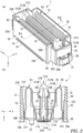
- a connector assembly 100 illustrated in Figures 1(a) and 1(b) includes a first connector 1 and a second connector 4 mated with each other, and is used for mechanical connection and electrical connection between circuit boards positioned in various electronic equipment.
- the first connector 1 includes a plurality of first contacts 10, and a fixed housing 20 and a movable housing 30 that retain the plurality of first contacts 10.
- the plurality of first contacts 10 are joined to a first circuit board 61 serving as a joining target.
- the first contacts 10 are positioned along a predetermined first direction x to form a first row R1 and a second row R2 in parallel, and are positioned on a first mounting surface 61A of the first circuit board 61.
- the second connector 4 includes a plurality of second contacts 40, and a housing 50 that retains the plurality of second contacts 40.
- the plurality of second contacts 40 are joined to a second circuit board 62.
- the second contacts 40 are also positioned to form a first row r1 and a second row r2 in parallel, and are positioned on a second mounting surface 62A of the second circuit board 62, similarly to the first contact 10.
- the first connector 1 and the second connector 4 are mated in a mating direction z orthogonal to the first mounting surface 61A and the second mounting surface 62A in a state where the first circuit board 61 and the second circuit board 62 are positioned in parallel.
- the first mounting surface 61A includes a first direction x, and s second direction y orthogonal to the first direction x and the mating direction z. This also applies to the second mounting surface 62A.
- the first circuit board 61 side in the mating direction z is referred to as the lower side, and a side opposite to the first circuit board 61 in the mating direction z is referred to as the upper side.
- the first connector 1 of the present embodiment allows relative displacement between the first circuit board 61 and the second circuit board 62 over a floating range corresponding to a dimension of a gap set in the first direction x and the second direction y, respectively, between the fixed housing 20 and the movable housing 30.
- the first connector 1 includes a plurality of first contacts 10, a fixed housing 20, and a movable housing 30 positioned so as to be relatively displaceable with respect to the fixed housing 20. Furthermore, the first connector 1 preferably includes a housing joining element 15 that joins the fixed housing 20 to the first circuit board 61, and a ground contact connecting element 17 ( Figure 12 ) that comes into contact with some contacts 10. Note that in some drawings, illustration of the ground contact connecting element 17 is omitted.
- the first contact 10 of the first row R1 and the first contact 10 of the second row R2 are respectively positioned at an equal pitch in the first direction x and adjacently positioned in the second direction y.
- the first contact 10 of the first row R1 and the first contact 10 of the second row R2 are arrayed such that the positions in the first direction x coincide. This is not the sole case, and the first contact 10 of the first row R1 and the first contact 10 of the second row R2 may be arrayed shifted in the first direction x by the dimension of 1/2 of the pitch.
- the fixed housing 20 is integrally formed by injection molding using resin material having insulating property. This is similar in the movable housing 30.
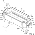
- the fixed housing 20 includes side walls 21, 22 and partial walls 23, 24 that surround the plurality of first contacts 10 and are positioned on the first mounting surface 61A, an expansion wall 25 formed on both sides of the fixed housing 20 in the first direction x to project out in the first direction x to the outer side of the partial walls 23, 24, a joining element retaining portion 26 that retains the housing joining element 15, a locating boss 27 inserted into a hole (not illustrated) formed in the first circuit board 61, and a leg portion 28 positioned on the first mounting surface 61A.
- the illustration of the boss 27 is omitted.
- the side walls 21, 22 extend in the first direction x in which the first contacts 10 are arrayed, and face each other in the second direction y.
- the partial walls 23, 24 orthogonal to the side walls 21, 22 are positioned on both sides of the second direction y between the side walls 21, 22, and are continued with the expansion wall 25.
- a space having a rectangular shape in top view in which the first contacts 10 are positioned is formed on the inner side of the walls 21 to 24.
- the leg portion 28 is formed at lower ends of four corners forming the walls 21 to 24.
- the side walls 21, 22 and the partial walls 23, 24 are raised with respect to the mounting surface 61A from the respective lower ends (e.g., 21A) to the upper end (e.g., 21B) slightly beyond the first contact 10.
- a gap G ( Figure 1(b) ) is formed between the lower ends of the walls 21 to 24 and the first mounting surface 61A.
- a retaining groove 211 to which the first contact 10 of the first row R1 is press-fitted is formed at the same pitch as the first contact 10 near the lower end of the inner side of the side wall 21.
- a retaining groove 221 to which the first contact 10 of the second row R2 is press-fitted is formed at the same pitch as the first contact 10 near the lower end of the inner side of the side wall 22.
- a chamfered portion 212 is formed on the upper side of the retaining groove 211 on the inner side of the side wall 21 to avoid interference between the first contact 10 and the fixed housing 20.
- the chamfered portion 212 is formed from the position above the retaining groove 221 to the position near the upper end 21B of the side wall 21.
- the chamfered portion 212 is inclined with respect to the mating direction z in a direction of separating in the second direction y with respect to a first zone 101 of the first contact 10 as it approaches a first curved portion C1 from a fixing retaining portion 10B.
- a chamfered portion 222 similar to the chamfered portion 212 is formed on the inner side of the side wall 22.
- the expansion wall 25 is formed to a rectangular shape in top view by a wall raised in the mating direction z from the lower end 25A to the upper end 25B.
- the upper end 25B is lower than the upper end 21B of the side wall 21 and the upper end 31B of the movable housing 30.
- the expansion wall 25 contributes to assembly of the fixed housing 20 and the movable housing 30 while receiving a part of each of the movable housing 30 and the second connector 4 on the inner side on both sides of the fixed housing 20 in the first direction x.
- the expansion wall 25 sets a floating range by setting a gap between the fixed housing 20 and the movable housing 30.
- the expansion wall 25 is preferably formed symmetrically in the first direction x with the walls 21 to 24 in between.
- the expansion wall 25 is formed with opposing portions 251 positioned facing each other toward the first mounting surface 61A on the inner side of the fixed housing 20.
- the opposing portion 251 sets a first gap G1 in the first direction x between the fixed housing 20 and the movable housing 30.
- the opposing portion 251 is extended in the first direction x and the second direction y and formed to a plate shape, and is supported by the wall of the expansion wall 25.
- the opposing portion 251 of the present embodiment is formed to a substantially C-shape in top view.
- a predetermined dimension x1 is given between the opposing portion 251 on one end side and the opposing portion 251 on the other end side in the first direction x.
- the housing 50 of the second connector 4 is positioned above the opposing portion 251 on the inner side of the expansion wall 25.
- the lower side of the opposing portion 251 of the expansion wall 25 corresponds to a lower region 252 ( Figure 4 ) that sets a second gap G2 in the second direction y between the fixed housing 20 and the movable housing 30.
- the lower region 252 includes side walls 252A, 252B extending in the first direction x and the mating direction z on the lower side of the opposing portion 251.
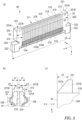
- the joining element retaining portion 26 is provided on the expansion wall 25 on both sides of the fixed housing 20 in the first direction x, and retains the housing joining element 15 illustrated in Figure 3 .
- the housing joining element 15 includes a joining portion 151 joined to the first circuit board 61 by a solder (not illustrated), and a press-fitting portion 152 having protrusions 152A on both sides.
- the joining element retaining portion 26 has a pair of grooves 261 for retaining the housing joining element 15 press-fitted from above along the mating direction z.
- An opening 253 is formed on the lower side of the opposing portion 251 in the expansion wall 25 and between the pair of grooves 261. Note that the opening 253 may not be formed in the expansion wall 25.
- the fixed housing 20 includes two pin-like bosses 27.
- the two bosses 27 project out in the mating direction z from the lower ends of the side walls 21, 22 or the partial walls 23, 24, and are spaced apart from each other in both the first direction x and the second direction y.
- the size of the diameter of the bosses 27 is different.
- the first connector 1 can be attached to the first circuit board 61 in a correct direction in which the two bosses 27 can be inserted to the holes of the first circuit board 61.
- the movable housing 30 divides the inner side of the fixed housing 20 to the first row R1 side and the second row R2 side, and retains the first contact 10 of the first row R1 and the contact 10 of the second row R2 together with the fixed housing 20.
- the movable housing 30 includes a retaining region 31 that extends in the first direction x at a length corresponding to the length of the rows R1, R2 and retains the first contact 10, and an expansion region 32 that is continued to both sides of the retaining region 31 in the first direction x, and is related to locating with respect to the second connector 4, assembly with the fixed housing 20, and setting of the floating range.
- the retaining region 31 is given a width (dimension in the second direction y) and a height (dimension in the mating direction z) necessary for retaining the first contact 10 of the first row R1 and the first contact 10 of the second row R2.
- a plurality of grooves 310 where each of the first contacts 10 is positioned are formed along the mating direction z.
- a guide inclined surface 31C for locating the movable housing 30 in the second direction y with respect to the second contact 40 of the second connector 4 is formed on the first row R1 side and the second row R2 side in the upper end 31B of the retaining region 31.
- the groove 310 includes a retaining groove 310A to which the first contact 10 is press-fit, and is continued over the entire height of the side surfaces 311, 312 as the entire groove 310.
- the grooves 310 are arrayed in the first direction x at a constant pitch.
- the depth (dimension in the second direction y) of the groove 310 changes in the mating direction z, as illustrated in Figure 2(b) .
- the retaining groove 310A is formed in the vicinity of the lower end 31A of the retaining region 31.
- a ground retaining groove 31D ( Figure 2(b) ) to which the ground contact connecting element 17 is press-fit is formed in the lower end 31A of the retaining region 31.
- a plurality of ground retaining grooves 31D depressed toward the upper side from the lower end 31A are interspersed in the first direction x.
- the expansion region 32 includes an upper part 320 formed with a guide protrusion 321 positioned on the upper side than the upper end 31B of the side surface 311, 312, and a lower part 322 positioned on a lower side than an opposing portion 251 of the fixed housing 20.
- the expansion region 32 is preferably formed symmetrically in the first direction x with the retaining region 31 in between.
- the expansion region 32 is formed with a concave portion 323 depressed in the first direction x at a position corresponding to the opposing portion 251.
- the upper part 320 and the lower part 322 are divided by the concave portion 323.
- the dimension in the mating direction z of the inner side of the concave portion 323 is the same as or larger than the plate thickness of the opposing portion 251.
- the opposing portion 251 is inserted to the inner side of the concave portion 323 depending on the relative position of the movable housing 30 and the fixed housing 20.
- the opposing portion 251 can be received in the concave portion 323 with the abutment of an end face 251A of the opposing portion 251 on a far surface 323A of the concave portion 323 as the limit.
- the guide protrusion 321 comes into contact with the housing 50 before the guide inclined surface 31C comes into contact with the housing 50 or the second contact 40 of the second connector 4, and guides the movable housing 30 in the first direction x and the second direction y following the position of the housing 50.
- the guide protrusion 321 is formed with an inclined surface 321A inclined with respect to the yz plane and an inclined surface 321B inclined with respect to the xz plane.
- a guide range y1 in which the movable housing 30 is displaceable in the second direction y by the guide from the inclined surface 321B is set for the inclined surface 321B of the guide protrusion 321.
- the guide range y1 is wider than the guide range y2 in which the movable housing 30 is displaceable in the second direction y by the guide from the guide inclined surface 31C.
- a guide range x3 in which the movable housing 30 is displaceable in the first direction x by the guide from the inclined surface 321A is set for the inclined surface 321A of the guide protrusion 321.
- the dimension x0 ( Figure 5(a) ) in the first direction x of the upper part 320 is small with respect to the dimension x1 ( Figure 4 ) between the opposing portions 251 on both sides.
- the dimension x2 ( Figure 5(a) ) in the first direction x of the lower part 322 is large with respect to the dimension x1 ( Figure 4 ) between the opposing portions 251 on both sides.
- the movable housing 30 can be inserted to the inner side of the fixed housing 20 from below until the lower part 322 abuts on a lower surface 251B of the opposing portion 251.
- the upper part 320 is accommodated in the fixed housing 20 up to a position beyond the opposing portion 251 on the upper side.
- the upper part 320 is mated with the housing 50 of the second connector 4.
- the housing 50 is positioned to surround the upper part 320 on the inner side of the fixed housing 20.
- the lower part 322 is positioned between the opposing portion 251 and the first mounting surface 61A of the first circuit board 61. Since the lower part 322 is sandwiched in the mating direction z by the opposing portion 251 and the first circuit board 61, the movable housing 30 is assembled to the fixed housing 20 and the first circuit board 61 in a state of not separating to the upper side and the lower side.
- the first connector 1 does not need to have a fixing metal fitting and the like for assembling the movable housing 30, the fixed housing 20, and the first circuit board 61, and the movable housing 30 and the fixed housing 20 are not restricted by such a fixing metal fitting and the like.
- a first gap G1 having a predetermined dimension is set between the end face 251A of the opposing portion 251 and the far surface 323A of the concave portion 323.
- a state in which the respective centers of the fixed housing 20 and the movable housing 30 in the first direction x coincide is illustrated.
- the relative displacement in the first direction x of the movable housing 30 to the right side or the left side of Figure 6 with respect to the fixed housing 20 from this state is allowed with the dimension of the first gap G1 as the limit.
- the first gap G1 is 1 mm
- a floating range of ⁇ 1 mm in the first direction x is given to the first connector 1.
- a second gap G2 is set between a side wall 322A of the lower part 322 and the inner surface of a side wall 252A of the lower region 252, and between the side wall 322B of the lower part 322 and the inner surface of the side wall 252B of the lower region 252.
- a state in which the respective centers of the fixed housing 20 and the movable housing 30 in the second direction y coincide is illustrated.
- the relative displacement in the second direction y of the movable housing 30 to the upper side or the lower side of Figure 7 with respect to the fixed housing 20 from this state is allowed with the dimension of the second gap G2 as the limit.
- the second gap G2 is 1 mm
- a floating range of ⁇ 1 mm in the second direction y is given to the first connector 1.
- the movable housing 30 and the fixed housing 20 are relatively displaceable in the first direction x and the second direction y, the movable housing 30 has a degree of freedom in position in the rotating direction as well within the xy plane with respect to the fixed housing 20. A floating range of a predetermined angle in the rotating direction within the xy plane is given to the first connector 1.
- Figures 8(a) to 8(c) show the first contact 10 in a state where load is not applied.
- the first contact 10 includes a joining portion 10A joined to the first mounting surface 61A by solder, a fixing retaining portion 10B retained in the fixed housing 20 by press-fitting, a movable retaining portion 10C retained in the movable housing 30 by press-fitting, and a connecting portion 10E that comes into contact with the second contact 40, and has a shape curved to be elastically deformable in the first direction x and the second direction y.
- the joining portion 10A positioned parallel to the first mounting surface 61A and the fixing retaining portion 10B form an L-shape in side view.
- a first curved portion C1 and a second curved portion C2 are formed between the fixing retaining portion 10B and the movable retaining portion 10C.
- the first curved portion C1 serving as a top portion of the first contact 10 has a reverse U-shape in side view.
- the second curved portion C2 has a substantially V-shape in side view.
- the lower end of the second curved portion C2 is located above the joining portion 10A.
- the connecting portion 10E has a substantially C-shape in side view.
- the upper end of the connecting portion 10E is located below the upper end of the first curved portion C1.
- the first contact 10 is bent to a substantially N-shape as an overall schematic shape.
- the first contact 10 is shaped by punching out a plate material made from a metal material such as copper alloy or the like to a linear elongate shape, and further performing bend processing.
- the floating range is set within a range of an elastic region of the first contact 10 for all directions of the first direction x, the second direction y, and the rotating direction within the xy plane.
- a material having satisfactory spring property is preferably used among the copper alloys for the material of the first contact 10 from the standpoint of increasing the floating range.
- the first contact 10 is given a constant plat thickness over a large portion in the length direction.
- a plate thickness t of the first contact 10 is determined within a range of, for example, 0.1 to 0.5 mm.
- the plate thickness of the connecting portion 10E is smaller than the plate thickness of other portions.
- the width w of the first contact 10 is determined at least to a value greater than or equal to the plate thickness t, for example, within a range of 0.1 to 0.5 mm.
- the width w of the first contact 10 changes in the length direction of the first contact 10. For example, in the entire length from the joining portion 10A to the connecting portion 10E of the first contact 10, the widths of the joining portion 10A and the connecting portion 10E are the narrowest to facilitate bending and to enhance the following property to the first mounting surface 61A and the second contact 40.
- a region on the upper side than the movable retaining portion 10C of the first contact 10 is given a width narrower than the width of the movable retaining portion 10C. The relevant region is smoothly inserted to the retaining groove 310A of the movable housing 30 from below.
- the first contacts 10 are positioned in a state where a gap g forms between adjacent first contacts 10 at a constant pitch P exceeding the maximum width w set to the first curved portion C1 and the second curved portion C2.
- the pitch P is, for example, 0.3 to 0.5 mm, and the first contacts 10 are densely positioned.
- the gap g is preferably greater than or equal to 0.15 mm.
- the first contact 10 are all positioned parallel to the xz plane.
- the first contact 10 of the first row R1 and the first contact 10 of the second row R2 are positioned line symmetrically with respect to an axis parallel to the mating direction z.
- the first contact 10 includes a first zone 101, a second zone 102, and a third zone 103.
- the first zone 101 extends from the fixing retaining portion 10B to the first curved portion C1 toward a side (upper side) opposite to the first mounting surface 61A.
- the second zone 102 extends from the first curved portion C1 that is convexly curved upward toward the first mounting surface 61A, and continues to the movable retaining portion 10C by way of the second curved portion C2.
- the third zone 103 extends from the movable retaining portion 10C to the connecting portion 10E connected to the second contact 40 toward a side opposite to the first mounting surface 61A.
- a first bent portion B1 formed to a convex shape toward the second zone 102 is formed in the first zone 101 .
- a second bent portion B2 formed to a convex shape toward the first zone 101 is formed at a position distant from the first mounting surface 61A than the position of the first bent portion B1 in the mating direction z.
- FIG. 9 shows a state in which a part of the second zone 102, the second curved portion C2, the movable retaining portion 10C, and a part of the third zone 103 of the first contact 10 are planarly developed including the second curved portion C2.
- the configuration of the first contact 10 adopted from the standpoint of manufacturing property related to the press-fitting step of the first contact 10, and impedance matching in the transmission path configured by the circuit boards 61, 62 and the connectors 1, 4 will be described.
- the first contact 10 includes a press-fitting portion 11 press-fitted to the movable housing 30, a pushing protrusion 12 including a pushing surface 12A pushed by a jig (not illustrated) at the time of press-fitting of the press-fitting portion 11, a first wide width region 13 continuing to the back side z+ of the pushing protrusion 12 in the press-fitting direction z in which the press-fitting portion 11 is press-fitted, a transitioning portion 16 interposed between the pushing protrusion 12 and the first wide width region 13, a second wide width region 14, and a transitioning portion 18.
- the movable retaining portion 10C corresponds to the press-fitting portion 11 and the pushing protrusion 12. As illustrated in Figure 8(a) , the movable retaining portion 10C and the fixing retaining portion 10B are formed in parallel with respect to the press-fitting direction z in side view.
- the first wide width region 13 includes the second curved portion C2.
- the first wide width region 13 is curved to a convex shape toward the back side z+ in the press-fitting direction z.
- the "press-fitting direction z" in the description related to the details of the first contact 10 corresponds to the mating direction z. Furthermore, the "width direction x" of the first contact 10 corresponds to the first direction x. Note that the second direction y corresponds to the thickness direction of the first contact 10.
- the back side z+ in the press-fitting direction z corresponds to the side (lower side) close to the first mounting surface 61A.
- the front side z- in the press-fitting direction z corresponds to the side (upper side) away from the first mounting surface 61A.
- the first contact 10 does not include twisted areas around the extending direction. Thus, the fracture surface of punching of the first contact 10 is directed only in the x direction, and is not directed in the y direction.
- the press-fitting portion 11, the pushing protrusion 12, the first wide width region 13, and the second wide width region 14 all have an edge E of both ends in the width direction x extending in parallel with respect to the press-fitting direction z.
- the press-fitting portion 11 is press-fitted to the retaining groove 310A ( Figure 10 ) of the movable housing 30 serving as the press-fitting target.
- the press-fitting portion 11 is formed over two stages with an interval in the press-fitting direction z.
- the first contact 10 extends from the press-fitting portion 11 toward the front side z- to the connecting portion 10E.
- Each of the two press-fitting portions 11 includes a press-fitting protrusion 111 projecting out to both sides in the width direction x with respect to a portion 11A having a narrow width adjacent to the press-fitting portion 11.
- the number of press-fitting portions 11 may be an appropriate number of greater than or equal to one.
- Each press-fitting protrusion 111 projects out in a trapezoidal shape in top view.
- Each press-fitting protrusion 111 has an inclined surface 11B on the front side z- in the press-fitting direction z, and has a perpendicular surface 11C on the back side z+.
- the inclined surface 11B is inclined with respect to the center line L1 in the width direction x of the press-fitting portion 11, and the perpendicular surface 11C is formed perpendicular to the center line L1.
- the pushing protrusion 12 projects out to one side x- in the width direction x on the back side z+ than the press-fitting portion 11 in the press-fitting direction z.
- the pushing protrusion 12 also serves as a protrusion for locating the press-fitting portion 11.
- the pushing protrusion 12 projects out beyond the position of the press-fitting portion 11 to one side x- in the width direction x. That is, the dimension in which the pushing protrusion 12 projects out in the width direction x from the narrow width portion 11A is larger than the dimension in which the press-fitting portion 11 projects out in the width direction x from the narrow width portion 11A.
- the pushing protrusion 12 projects out only to one side in the width direction x with respect to the portion 11A having a narrow width adjacent to the press-fitting portion 11.
- the edge E on the side opposite to the pushing protrusion 12 in the width direction x extends on the same straight line as the edge of the portion 11A having a narrow width.
- a required clearance X2 can be between the respective pushing protrusions 12 of the first contacts 10 positioned side by side in the width direction x, from the position of the edge E on the side opposite to the pushing protrusion 12 to the position not overlapping the pushing protrusion 12 of the first contact 10 adjacent in the width direction x as the limit.
- the clearance X2 is set to, for example, greater than or equal to 60% of the plate thickness t of the pushing protrusion 12 to avoid damage of an element (corresponds to punch, die) used in the punching step (stamping step) while preventing the first contacts 10 from coming into contact with each other. This is the same for clearances X1, X3, and X4.
- the array state of the first contacts 10 when punched out from the sheet material at the time of stamping processing corresponds to the array state of the first contacts 10 when provided in the first connector 1.
- the width W2 of the pushing protrusion 12 is set in view of the width of the pitch P, the clearance X2, and the width necessary for the thin portion 11A of the press-fitting portion 11. For example, when the pitch P is 0.5 mm and the clearance X2 of at least 0.12 mm is required, the width W2 needs to be suppressed to less than or equal to 0.38 mm.
- the pushing protrusion 12 is also formed to a trapezoidal shape.
- An inclined surface 12B is formed on the front side z-of the pushing protrusion 12.
- a pushing surface 12A to be pushed by the press-fitting jig (not illustrated) is formed perpendicular to the center line L1 on the back side z+ of the pushing protrusion 12.
- the press-fitting portion 11, the pushing protrusion 12, and the first wide width region 13 are illustrated, together with the retaining groove 310A of the movable housing 30.
- the pushing surface 12A and the second curved portion C2 are illustrated.
- the projection amount of the pushing protrusion 12 is larger than the projection amount of the press-fitting protrusion 111, and thus the pushing surface 12A is large in the width direction x as compared with the perpendicular surface 11C of the press-fitting protrusion 111.
- the press-fitting jig may not be positioned on the perpendicular plane 11C but the press-fitting jig can be positioned on the pushing surface 12A formed on the pushing protrusion 12.
- a width of greater than or equal to 0.1 mm, for example, can be ensured in the pushing surface 12A, and thus the pushing surface 12A can be stably pushed with the press-fitting jig.
- the plate thickness of the first contact 10 is constant except for the connecting portion 10E, ensuring sufficient width in the region 13 contributes to impedance matching.
- the first wide width region 13 on the back side z+ than the pushing surface 12A is shifted to the side x+ opposite to one side x- in the width direction x in which the pushing protrusion 12 projects out with respect to the press-fitting portion 11.
- the press-fitting jig is positioned on the back side (z+) of the pushing surface 12A in the press-fitting direction z, and pushes the pushing surface 12A toward the front side z- in the press-fitting direction z, as indicated with an arrow J in Figures 8(b) and 8(c) .
- the pushing surface 12A is opened to the back side z+ in the press-fitting direction (z) to arrange the press-fitting jig. That is, the region 12C ( Figure 9 ) projected toward the back side z+ from the pushing surface 12A does not include the edge E of the transitioning portion 16 continuing to the back side z+ from the pushing surface 12A nor the edge E of the first wide width region 13.
- the edge E of the transitioning portion 16 and the edge E of the first wide width region 13 both extend to the back side z+ perpendicularly to the pushing surface 12A.
- the press-fitting jig can be positioned without interfering with the transitioning portion 16 and the first wide width region 13. Note that a lowermost end of the first contact 10 in the projection region 12C is the top portion T of the second curved portion C2, and thus when the press-fitting jig is inserted from the back side z+ side in the press-fitting direction z, it may be sufficient to be opened from the pushing surface 12A to the top portion T of the second curved portion C2.
- the first wide width region 13 is shifted to the side x+ opposite of one side x- in which the pushing protrusion 12 projects out with respect to the press-fitting portion 11. That is, the center line L3 of the first wide width region 13 is shifted to the x+ side of the width direction x with respect to the center line L1 in the press-fitting portion 11.
- the pushing surface 12A is opened to the back side z+ of the press-fitting direction z, and the first wide width region 13 has a width W3 wider than the width W1 of the press-fitting portion 11.
- the first wide width region 13 may be given a width wide as possible while setting a necessary clearance X3 between the first wide width regions 13 positioned side by side in the width direction x, with a distance from the position of the edge E perpendicular to the pushing surface 12A to the position not overlapping with the projection region 12C of the pushing surface 12A of the first contact 10 adjacent on the x+ side in the width direction x as the limit.
- the width W3 of the first wide width region 13 may be the same as the width W2 at the position of the pushing protrusion 12.
- the ratio of the width with respect to the plate thickness can be sufficiently ensured in order to stably perform the processing of punching and bending of the first contact 10. Twist is less likely to occur at the time of processing the larger the ratio of the width with respect to the plate thickness.
- the width W3 of the first wide width region 13 is preferably constant from the standpoint of stability of processing and impedance matching.
- the first wide width region 13 has the second curved portion C2 connected to the pushing protrusion 12 by way of the transitioning portion 16 at the position exceeding the connecting portion 10E side.
- the range where the bending process is performed it is preferable to avoid changing the width or shifting the position in the width direction.
- the range where the bending process of the second curved portion C2 is performed falls within the first wide width region 13.
- the transitioning portions 16, 18 where the width and the position are switched do not exist, and thus the bending process of the second curved portion C2 is stably performed.
- the transitioning portion 16 gradually widens to the x+ side in the width direction x by an inclined surface 16B from a portion 16A having a narrow width to the first wide width region 13, and continues to the first wide width region 13. Since it is a disadvantage from the standpoint of impedance matching if the width is narrow compared with the pushing protrusion 12 and the first wide width region 13, the length of the portion 16A in the press-fitting direction z is preferably as short as possible.
- the width of the transitioning portion 16 preferably gradually increases toward the back side z+ due to the concentration of stress at the time of bending process and influence on impedance matching caused by the sudden change in width.
- an angle ⁇ formed by the inclined surface 16B with respect to the portion 16A is, for example, set to 45° with respect to the center line L1.
- a corner c of the pushing surface 12A of the pushing protrusion 12 and the transitioning portion 16 of the first contact 10 adjacent on the x- side are positioned separated in the press-fitting direction z at an extent necessary for avoiding the contact of the first contacts 10.
- the first contact 10 preferably includes a second wide width region 14 continuing to the side opposite to the pushing protrusion 12 side of the first wide width region 13.
- the second wide width region 14 belongs to the first zone 101 and the second zone 102.
- the second wide width region 14 is shifted to the x- side which is a direction in which the pushing protrusion 12 projects out with respect to the first wide width region 13.
- the width of the second wide width region 14 can be widened to the pushing surface 12A side.
- the width of the second wide width region 14 is not only wider than the press-fitting portion 11 but is also wider than the first wide width region 13.
- a sufficient width W4 is given to the second wide width region 14 to reduce impedance while ensuring a necessary clearance X4 between the second wide width regions 14 positioned side by side in the width direction x.
- the width W4 and the width W2 of the pushing protrusion 12 described above correspond to the maximum width in the first contact 10.
- the second wide width region 14 is given a constant width W4 up to the position beyond the first curved portion C1 on the joining portion 10A side in the second zone 102, and the clearance X4 is also constant.
- the second wide width region 14 has a widest width and has a long extending length in the first contact 10, and thus greatly contributes to improving the impedance matching.
- the second wide width region 14 goes beyond the first curved portion C1 to the joining portion 10A side, and continues to the fixing retaining portion 10B through the region r where the width gradually decreases.
- the center line L4 of the second wide width region 14 coincides with the center line L1 if extended to the press-fitting portion 11, and also coincides with the center line (not illustrated) in the width direction x of the joining portion 10A if further extended. Furthermore, the center line L4 of the second wide width region 14 coincides with the center line (not illustrated) in the width direction x of the joining portion 10A if extended to the joining portion 10A.
- the position of the first contact 10 in the width direction x returns to the same position as the press-fitting portion 11 in the second wide width region 14 through the pushing protrusion 12 projecting out to one side in the width direction x and the first wide width region 13 shifted with respect to the press-fitting portion 11 from the press-fitting portion 11. That is, the press-fitting portion 11, the pushing protrusion 12, the first wide width region 13, and the second wide width region 14 are shifted to one side x- and the other side x+ in the width direction x to be formed to a zigzag shape as a whole.
- the dimension in the width direction x can be suppressed as a whole from one end to the other end in the extending direction of the first contact 10 by returning from the first wide width region 13 shifted to the x+ side with respect to the press-fitting portion 11 to the same position as the press-fitting portion 11 in the width direction x due to the existence of the second wide width region 14.
- it can contribute to downsizing of the connector 1 as compared with a case of not returning.
- the first wide width region 13 is connected to the second wide width region 14 through the transitioning portion 18 at a position beyond the second curved portion C2 on the first curved portion C1 side.
- the transitioning portion 18 has a narrow width between the first wide width region 13 and the second wide width region 14, and includes a short part 18C in the press-fitting direction z. This transitioning portion 18 is also preferably short as possible from the standpoint of impedance matching.
- the inclined surface 18A on the front side z- of the transitioning portion 18 and the inclined surface 18B on the back side z+ of the transitioning portion 18 adjacent on the x+ side are positioned separated in the press-fitting direction z at an extent necessary for avoiding contact between the first contacts 10.
- the position of the first contact 10 in the width direction x does not return to the position of the press-fitting portion 11 by the transitioning portion 18 and the second wide width region 14, and the first wide width region 13 extends toward the joining portion 10A in a state of being shifted with respect to the press-fitting portion 11.
- as wide as possible width of the first wide width region 13 is preferably ensured from the position corresponding to the transitioning portion 18 to the position beyond the first curved portion C1.
- both ends of the first contact 10, that is, the connecting portion 10E and the joining portion 10A are shifted in the width direction x, the terminal of the first circuit board 61 and the mating contact 40 are positioned in accordance with the positions of the connecting portion 10E and the joining portion 10 A.
- the fixing retaining portion 10B of the fixed housing 20 includes a press-fitting portion 10B1 and a pushing protrusion 10B2.
- the press-fitting portion 10B1 is configured similarly to the press-fitting portion 11 of the movable retaining portion 10C, and is press-fitted to the fixed housing 20 in the same press-fitting direction z.
- the pushing protrusion 10B2 is located on the back side z+ than the press-fitting portion 10B1 in the press-fitting direction z.
- This pushing protrusion 10B2 is formed with a pushing surface 10B3 having a width same as the pushing surface 12A of the pushing protrusion 12 of the movable retaining portion 10C.
- the pushing surface 10B3 is opened to the back side z+ of the press-fitting direction z.
- the back side z+ of the pushing protrusion 10B2 of the fixing retaining portion 10B is continued to the joining portion 10A.
- the projection amount of the pushing protrusion 10B2 to one side x+ in the width direction x is the same as the projection amount of the press-fitting protrusion p of the press-fitting portion 10B1 to the same x+ side. That is, the projection amount of the pushing protrusion 10B2 is smaller than the projection amount of the pushing protrusion 12 of the movable retaining portion 10C.
- the edge E1 on the x- side of the pushing protrusion 10B2 is on the extension line of the edge E0 of the press-fitting protrusion p.
- the joining portion 10A is formed by the edge E1 and the edge E2 perpendicular to the pushing surface 10B3.
- the width of the joining portion 10A may be, for example, the same as the width of the portion having a narrow width of the press-fitting portion 10B1.
- the fixing retaining portion 10B, and furthermore, the retaining portion 40B of the second contact 40 to be described later may include the pushing protrusion 12, the first wide width portion 13, and the like similarly to the movable retaining portion 10C.
- One part of the first contact 10 configuring the first row R1 corresponds to a signal potential of an electronic circuit including the first circuit board 61 and the second circuit board 62, and the remaining part corresponds to a ground potential in the electric circuit.
- one part of the first contact 10 configuring the second row R2 corresponds to a signal potential in the electronic circuit, and the remaining part corresponds to a ground potential in the electronic circuit.
- the allocation for signal/ground with respect to the first contact 10 is appropriately designed. In the allocation for signal/ground, various patterns exist depending on the product.
- the ground contact connecting element 17 comes into contact with only a ground contact group GG including a plurality of first contacts 10 allocated for ground among all the first contacts 10.
- the first contacts 10 to which the ground contact connecting element 17 comes into contact all have the same potential.
- the reference numerals of GG are illustrated divided into four parts for the sake of convenience of illustration.
- the ground contact group GG corresponds to the first contact 10 of one group corresponding to the ground potential
- the ground contact group GG corresponds to the first contact 10 of one part of the first row R1 and the first contact 10 of one part of the second row R2, for the ground contact connecting element 17 as a whole.
- the ground contact connecting element 17 includes a supporting portion 171 provided at the lower end 31A of the movable housing 30 and extending in the first direction x, and a plurality of contact beams 172 that come into contact with the second curved portions C2 of each of the first contacts 10 configuring the ground contact group GG.
- the contact beam 172 is positioned between the lower end 31A and the first mounting surface 61A, and comes into contact with the second curved portion C2 of the first contact 10 adjacent to the lower end 31A from the first mounting surface 61A side.
- the second curved portion C2 of the first contact 10 is located in the vicinity of the movable retaining portion 10C retained by the movable housing 30, and thus displaces following the movable housing 30.
- the distance between the second curved portion C2 and the movable housing 30 barely changes.
- the contact beam 172 is in contact with the second curved portion C2
- the behavior in which the movable housing 30 displaces within the floating range with respect to the fixed housing 20 is not affected.
- the supporting portion 171 is provided with a plurality of retaining portions 171A to be press-fitted to each ground retaining groove 31D of the movable housing 30.
- the press-fitting protrusion 171B is formed on both sides of the retaining portion 171A in the first direction x.
- the contact beam 172 projects out in the second direction y toward the ground contact 10 of the first row R1 or the ground contact 10 of the second row R2 perpendicularly from the supporting portion 171.
- the length of the contact beam 172 extending toward the first row R1 side from the supporting portion 171 and the length of the contact beam 172 extending toward the second row R2 side from the supporting portion 171 are different, but they may be the same.
- the width (dimension in the first direction x) of the contact beam 172 is narrower than the width (dimension in the first direction x) at the area of coming into contact with the contact beam 172 of the first contact 10.
- the width of the contact beam 172 may be the same as the joining portion 10A and the connecting portion 10E of the first contact 10.
- the ground contact connecting element 17 can be shaped by performing processing of punching and bending on the metal plate material such as copper alloy.
- the retaining portion 171A is bent perpendicularly on one side of the supporting portion 171 in the width direction (second direction y).
- the retaining portion 171A can be formed at an arbitrary part in the first direction x excluding the area (e.g., x4 in Figure 12 ) where the contact beam 172 is formed on both sides of the supporting portion 171 in the width direction.
- the ground contact connecting element 17 can respond to various products by customizing the position of the contact beam 172 and the retaining portion 171A according to the pattern of allocation for signal/ground.
- the movable housing 30 in which the position of the ground retaining groove 31D is different is preferably producible by having the portion corresponding to the ground retaining groove 31D in the shaping die of the movable housing 30 as a nest.
- the SI (Signal Intensity) performance can be enhanced, as illustrated in the analysis result of frequency characteristics of insertion loss (IL) in Figure 19 , for example, by using the ground contact connecting element 17.
- the broken line in Figure 19 indicates the insertion loss frequency characteristics when the first connector 1 does not include the ground contact connecting element 17, and the solid line indicates the insertion loss frequency characteristics when the first connector includes the ground contact connecting element 17.
- the one dot chain line schematically shows the required specification. From Figure 19 , it can be seen that the peak of the resonance frequency shifts to the high frequency side by using the ground contact connecting element 17. As a result of the design margin on the required specification enlarging from M1 to M2 accompanying therewith, the SI performance enhances.
- the second connector 4 includes a plurality of second contacts 40, a housing 50 for retaining the same, and a joining element 45, and is mated with the movable housing 30.
- the second contact 40 of the first row r1 and the second contact 40 of the second row r2 are positioned at a constant pitch P in the first direction x similarly to the first contact 10, and are adjacent in the second direction y.
- the second contact 40 is shaped by punching out a plate raw material made from a metal material such as copper alloy or the like to a linear elongate shape, and further performing bend processing.
- the second contact 40 includes a joining portion 40A joined to the second circuit board 62, a retaining portion 40B retained by the housing 50, and a connecting portion 40C electrically connected to the first contact 10.
- the second contact 40 of the present embodiment has a zone 401 extending perpendicular to the joining portion 40A, and is formed to an L-shape as a whole.
- the zone 401 includes the retaining portion 40B and the connecting portion 40C.
- the retaining portion 40B includes a press-fitting portion 40B1 and a pushing protrusion 40B2 similar to the press-fitting portion 10B1 and the pushing protrusion 10B2 of the fixing retaining portion 10B, and is formed in the vicinity of the joining portion 40A in the zone 401.
- a region on the lower side than the retaining portion 40B in the zone 401 corresponds to the connecting portion 40C.
- the connecting portion 10E of the first contact 10 of the first row R1 and the connecting portion 10E of the first contact 10 of the second row R2 are inserted between the connecting portion 40C of the first row r1 and the connecting portion 40C of the second row r2.
- the housing 50 surrounds the second contacts 40 of the first row r1 and the second row r2 from four sides, and includes walls 51 to 54 positioned on the second mounting surface 62A, a joining element retaining portion 56 for retaining the joining element 45, two bosses 57 ( Figure 1(a) ) for locating inserted to a hole (not illustrated) of the second circuit board 62, and a leg portion 58 positioned on the second mounting surface 62A.
- the side wall 51 and the side wall 52 extend in the first direction x at a length corresponding to the length of the rows r1, r2, and face each other in the second direction y.
- the grooves 511 in which the second contacts 40 of the first row r1 are respectively positioned are formed along the mating direction z.
- the groove 511 includes a retaining groove 511A to which the second contact 40 is press-fitted.
- the grooves 521 in which the second contacts 40 of the second row r2 are respectively positioned and includes a retaining groove 521A are formed along the mating direction z.
- a guide inclined surface 512 is formed to relatively locate the movable housing 30 of the first connector 1 and the housing 50 in the second direction y.
- a similar guide inclined surface 522 is formed on the inner side at the lower end of the side wall 52 as well.
- the guide inclined surfaces 512, 522 are symmetrically formed in the second direction y.
- the distal end of the connecting portion 40C is positioned adjacent to the guide inclined surfaces 512, 522, as illustrated in Figure 14(b) .
- the joining portion 40A is positioned on the outer side of the grooves 511, 521.
- the joining portion 40A is located slightly above the position of the leg portion 58.
- the distance d1 in the second direction y between the connecting portion 40C of the second contact 40 of the first row r1 and the connecting portion 40C of the second contact 40 of the second row r2 is smaller than the distance d2 ( Figure 2(b) ) in the second direction y between the vertex of the connecting portion 10E of the first contact 10 of the first row R1 and the vertex of the connecting portion 10E of the first contact 10 of the second row R2.
- the connecting portion 10E of the first contact 10 of the first row R1 comes into contact with the connecting portion 40C of the second contact 40 at the vertex while being pressed between the second contact 40 of the first row r1 and the movable housing 30.
- This is the same for the connecting portion 10E of the first contact 10 of the second row R2.
- the connecting portions 40C of the second contact 40 can stably bring into contact the connecting portion 40C and the connecting portion 10E as they are linearly formed in the mating direction z even if the positions of the first contact 10 and the second contact 40 in the mating direction z are shifted.
- the walls 53, 54 are provided at both ends in the first direction x of the side walls 51, 52, and face each other in the first direction x.
- the height of the walls 53, 54 from the second mounting surface 62A is higher than the height of the side walls 51, 52 from the second mounting surface 62A.
- the first guide inclined surface 55 inclined with respect to the yz plane is formed at both ends in the first direction x of the walls 51 to 54.
- the second guide inclined surface 59 inclined with respect to the xz plane is formed at four corners of the walls 51 to 54.
- the guide inclined surfaces 55, 59 are positioned below the lower ends 51A, 52A of the side walls 51, 52.
- the first guide inclined surface 55 is symmetrically formed in the first direction x.
- the second guide inclined surface 59 is symmetrically formed in the second direction y.
- the first guide inclined surface 55 comes into contact with the inclined surface 321A of the guide protrusion 321 of the movable housing 30 before the guide inclined surfaces 512, 522 of the side walls 51, 52 come into contact with the guide inclined surface 31C of the movable housing 30, and guides the movable housing 30 in the first direction x following the position of the housing 50.
- the second guide inclined surface 59 comes into contact with the inclined surface 321B of the guide protrusion 321 of the movable housing 30 before the guide inclined surfaces 512, 522 of the side walls 51, 52 come into contact with the guide inclined surface 31C of the movable housing 30, and guides the movable housing 30 in the second direction y following the position of the housing 50.
- the first guide inclined surface 55 is inclined with respect to the yz plane.
- the second guide inclined surface 59 is inclined with respect to the xz plane.
- a guide range x3 ( Figure 14(a) ) same as that of the inclined surface 321A of the guide protrusion 321 of the movable housing 30 is set in the first guide inclined surface 55.
- the guide range x3 is preferably larger than the dimension of the first gap G1.
- a guide range y1 ( Figure 14(b) ) same as that of the inclined surface 321B of the guide protrusion 321 of the movable housing 30 is set in the second guide inclined surface 59.
- the guide range y1 is preferably larger than the dimension of the second gap G2.
- the joining element 45 includes a joining portion 451 to be joined to the second circuit board 62 and a press-fitting portion 452 having protrusions 452A on both sides.
- the joining element retaining portion 56 is provided on the outer side of the walls 53, 54.
- the joining element retaining portion 56 is formed with a retaining groove 56A to which the joining element 45 is press-fitted from below.
- first contact of the present embodiment Effect by first contact of the present embodiment.
- the pushing protrusion 12 in which the projection amount in the width direction x is larger than the press-fitting portion 11 is formed, and the first wide width region 13 is shifted in the width direction x in a direction opposite to the direction in which the pushing protrusion 12 projects out with respect to the press-fitting portion 11.
- the first contacts 10 are positioned densely, the dimension in the width direction x necessary for the pushing surface 12A pushed by the jig can be ensured, and thus the manufacturing property of the first contact 10 can be satisfied.
- sufficient width W3 can be given to the first wide width region 13 while ensuring the clearance X3, and hence satisfactory impedance matching of the transmission path including the first contact 10 can be realized.
- the configuration of the first contact 10, of course, does not influence the floating range and the floating performance of the connector assembly 100.
- the housing joining element 15 is press-fitted from above to each of a pair of grooves 261 provided in each expansion wall 25 on both sides of the fixed housing 20 ( Figure 2(a) ). Furthermore, the movable housing 30 is positioned on the inner side of the fixed housing 20 from below ( Figure 2(b) , Figure 6 ).
- a plurality of first contacts 10 can be attached from below to the fixed housing 20 and the movable housing 30 while using a jig (not illustrated).
- the fixed housing 20 and the movable housing 30 are supported at a predetermined position by a first jig, and the first contacts 10 of the first row R1 and the second row R2 are pushed upward by a third jig for press-fitting in contact with the pushing surface 10B3 and a third jig for press-fitting in contact with the pushing surface 12A while aligning the first contacts 10 in the first row R1 and the second row R2 by the second jig.
- the first contacts 10 of each row R1, R2 are inserted between the fixed housing 20 and the movable housing 30 from the first curved portion C1 and the connecting portion 10E side.
- the fixing retaining portion 10B of the first contact 10 of the first row R1 is press-fitted to the retaining groove 211 of the fixed housing 20
- the movable retaining portion 10C of the first contact 10 of the first row R1 is press-fitted to the retaining groove 310A on the first row R1 side of the movable housing 30.
- the fixing retaining portion 10B of the first contact 10 of the second row R2 is press-fitted to the retaining groove 221 of the fixed housing 20, and the movable retaining portion 10C of the first contact 10 of the second row R2 is press-fitted to the retaining groove 310A on the second row R2 side of the movable housing 30.
- the movable housing 30 When the fixing retaining portion 10B and the movable retaining portion 10C are press-fitted, the movable housing 30 is supported by the second curved portion C2 of the first contact 10 of the first row R1 and the second curved portion C2 of the first contact 10 of the second row R2. At this time, the lower end 31A of the movable housing 30 is located above the leg portion 28 of the fixed housing 20. The second curved portion C2 is located below the lower end 31A of the movable housing 30 and is located above the leg portion 28. The joining portion 10A of the contact 10 is located on the slightly lower side of the leg portion 28 of the fixed housing 20.
- each contact beam 172 is bent in the plate thickness direction, and pressed in the mating direction z with respect to the second curved portion C2 of the first contact 10 for ground.
- the contact beam 172 can be stably brought into contact with the contact group GG.
- the SI performance thus can be stabilized by having the contacts 10 for ground at the same potential by an element 17 including the contact beam 172 stably brought into contact with the first contact 10.
- the assembly of the first connector 1 is thereby completed ( Figures 2(a), 2(b) ).
- the movable housing 30 is supported in a state having degree of freedom in position over the floating range in the first direction x, the second direction y, and the rotating direction within the xy plane by the elastic deformation of the first contact 10 of the first row R1 and the first contact 10 of the second row R2.
- the second contacts 40 are inserted to the grooves 511, 521 of the housing 50 from above while being aligned in the first row r1 and the second row r2 using a jig (not illustrated), and the pushing surface 40B3 is pushed to press-fit the second contacts 40 into the retaining grooves 511A, 521A. Furthermore, the joining element 45 is press-fitted to the joining element retaining portion 56. As described above, the assembly of the second connector 4 is completed.
- the boss 57 of the housing 50 is inserted to a hole (not illustrated) of the second circuit board 62, and the leg portion 58 is brought into contact with the second mounting surface 62A.
- the joining portion 40A of each second contact 40 is joined to the second mounting surface 62A by solder, and the joining portion 451 of the joining element 45 is joined to the second mounting surface 62A by solder.
- the respective positions in the second direction y of the first connector 1 and the second connector 4 may not necessarily coincide, as illustrated in Figure 16 , due to the accumulated tolerance of tolerances and the like of dimensional shape, processing and assembly of the elements.
- the first connector 1 and the second connector 4 are mated to obtain the connector assembly 100 based on the configuration of the first connector 1, and the first circuit board 61 and the second circuit board 62 can be assembled.
- the movable housing 30 In a state in which the movable housing 30, the fixed housing 20, and the first circuit board 61 are assembled, the movable housing 30 is supported by the fixed housing 20 through the first contact 10. That is, the movable housing 30 is supported in a displaceable manner by elastically deforming the first contact 10 in the first direction x and the second direction y.
- the lower part 322 of the movable housing 30 and the opposing portion 251 of the fixed housing 20 face each other in the mating direction z, and the relative displacement of the movable housing 30 including the lower part 322 and the fixed housing 20 including the opposing portion 251 in the first direction x and the second direction y can be performed within a range of the floating range corresponding to the gaps G1, G2 set between the movable housing 30 and the fixed housing 20.
- the movable housing 30 and the fixed housing 20 are assembled by arranging the lower part 322 between the opposing portion 251 and the first circuit board 61, the movable housing 30 and the fixed housing 20 are not restrained by metal fitting or the like for assembly. The relative displacement between the movable housing 30 and the fixed housing 20 are thus not inhibited by the metal fitting, and hence sufficient floating range can be ensured over the entire gaps G1, G2.
- the first connector 1 capable of enlarging the floating range to a scale of greater than or equal to ⁇ 1 mm and a connector assembly 100 can be provided.
- the movable housing 30 displaces in the second direction y with respect to the fixed housing 20 while elastically deforming the first contact 10 in the second direction y following the position of the housing 50.
- first contacts 10 of either the first row R1 and the second row R2 are deformed in the direction in which the fixing retaining portion 10B and the movable retaining portion 10C move closer to each other
- first contacts 10 of the other row are deformed in the direction in which the fixing retaining portion 10B and the movable retaining portion 10C move away from each other.
- the first zone 101 is inclined with respect to the mating direction z, so that the first curved portion C1 side of the first zone 101 moves closer to the side wall 21 of the fixed housing 20 with respect to the fixing retaining portion 10B side.
- a chamfered portion 212 having a shape that follows the direction of the inclination of the first zone 101 at this time is formed on the inner side of the side wall 21 of the fixed housing 20, the first zone 101 does not come into contact with the fixed housing 20.
- the first connector 1 and the second connector 4 allows a positional shift amount corresponding to a predetermined floating range in the first direction x, the second direction y, and the xy rotating direction based on the first gap G1 and the second gap G2.
- the movable housing 30 is guided in the second direction y by the action of the inclined surface 321B of the guide protrusion 321 and the second guide inclined surface 59 of the housing 50, so that an approximate position in the second direction y is determined, and thereafter, it is positioned in the second direction y with respect to the housing 50 by the action of the guide inclined surface 31C and the guide inclined surfaces 512, 522.
- the movable housing 30 and the housing 50 can be smoothly mated.
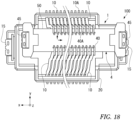
- Figure 18 shows a state in which positional shift between the first connector 1 and the second connector 4 has occurred in both the first direction x and the second direction y.
- the movable housing 30 displaces with respect to the fixed housing 20 and the housing 50 by the action of the guide inclined surface 31C and the guide inclined surfaces 512, 522 following the action of the inclined surfaces 321A, 321B and the guide inclined surfaces 55, 59 of the guide protrusion 321 within the range of the floating range.
- each first contact 10 is elastically deformed in the first direction x and the second direction y.
- the joining target to which the first contact 10 is joined is not necessarily limited to the circuit board.
- the joining target of the second contact 40 is also not necessarily limited to the circuit board.
- the opposing portion 251 formed in the fixed housing 20 and the a part of the movable housing 30 positioned between the opposing portion 251 and a reference surface (first mounting surface 61A) of the joining target is not limited to the above embodiment, and can be appropriately configured.
- the first gap G1 is not only set between the opposing portion 251 and the concave portion 323 as in the above embodiment, and may set between the movable housing 30 and the fixed housing 20 at a position separated from the opposing portion 251 and the concave portion 323.
- the second gap G2 is also not only set between the side walls 322A, 322B of the expansion region 32 and the side walls 252A, 252B of the expansion wall 25 as in the above embodiment, and may be set between the movable housing 30 and the fixed housing 20 at a position separated from the expansion region 32 and the expansion region 25.
- a contact (10) including, a press-fitting portion (11) press-fitted to a press-fitting target (30) in a press-fitting direction (z), a pushing protrusion (12) projecting out to one side (x-) in a width direction (x) intersecting the press-fitting direction (z) on a back side (z+) of the press-fitting portion (11) in the press-fitting direction (z), and a first wide width region (13) continuing on the back side (z+) of the pushing protrusion (12), where the pushing protrusion (12) projects out beyond a position of the press-fitting portion (11) to one side (x-) in the width direction (x), the first wide width region (13) shifts to the other side (x+) in the width direction (x) with respect to the press-fitting portion (11), and is wide in the width direction (x) as compared with the press-fitting portion (11), and a pushing surface (12A) on the back side (z+) of
- the contact (10) according to any one of paragraphs [127] to [130], further including, a second retaining portion (10C) including the press-fitting portion (11) and the pushing protrusion (12) and being retained by a second housing (30) serving as the press-fitting target (30), and a first retaining portion (10B) retained by a first housing (20) of a separate body from the second housing (30), where the first retaining portion (10B) is press-fitted to the first housing (20) in the same direction as the press-fitting direction (z) of the press-fitting portion (11), a first curved portion (C1) curved to a convex shape toward a front side (z-) is formed on the first retaining portion (10B) side between the first retaining portion (10B) and the second retaining portion (10C), and a second curved portion (C2) curved to a convex shape toward the back side (z+) in the press-fitting direction (z) is formed on the second retaining portion (10C) side between the first retaining portion (10B
- the contact (10) according to paragraph [131], further including a first zone (101) extending from the first retaining portion (10B) to the first curved portion (C1) toward the front side (z-) in the press-fitting direction (z), a second zone (102) extending from the first curved portion (C1) toward the back side (z+) and continuing to the second retaining portion (10C) through the second curved portion (C2), and a third zone (103) extending from the second retaining portion (10C) to a connecting portion (10E) connected to a mating contact (40) toward the front side (z-), where the first zone (101) is formed with a first bent portion (B1) formed to a convex shape toward the second zone (102), and the second zone (102) is formed with a second bent portion (B2) formed to a convex shape toward the first zone (101) on the front side (z-) of the position of the first bent portion (B1) in the press-fitting direction (z).
- a connector (1) including, a plurality of contacts (10) described in any one of paragraphs [127] to [132], the plurality of contacts (10) being arrayed along the width direction (x) while forming a first row (R1) and a second row (R2) in parallel, a second housing (30) serving as the press-fitting target (30), and a first housing (20) that retains the plurality of contacts (10) together with the second housing (30) and supports the second housing (30) by way of the contacts (10), where the second housing (30) divides the inner side of the first housing (20) into the first row (R1) side and the second row (R2) side, and is positioned to be relatively displaceable in a direction (y) intersecting both the width direction (x) and the press-fitting direction (z) with respect to the first housing (20).
- the connector (1) according to paragraph [133] or [134], further including, a plurality of contacts (10) described in (6), the plurality of contacts (10) arrayed along the width direction (x) while forming a first row (R1) and a second row (R2) in parallel, a second housing (30) serving as the press-fitting target (30), and a first housing (20) that retains the plurality of contacts (10) together with the second housing (30) and supports the second housing (30) by way of the contacts (10), where the second housing (30) divides the inner side of the first housing (20) into the first row (R1) side and the second row (R2) side, and is positioned to be relatively displaceable in the width direction (x) and a direction (y) intersecting both the width direction (x) and the press-fitting direction (z) with respect to the first housing (20), the first row (R1) and the second row (R2) are adjacent in a thickness direction (y) of the contact (10) orthogonal to both the width direction (x) and the press-fitting direction (z
- a connector assembly (100) including, a first connector (1) serving as the connector described in any one of paragraphs [133] to [135], and a second connector (4) to be mated with the second housing (30) of the first connector (1).
Landscapes
- Coupling Device And Connection With Printed Circuit (AREA)
- Details Of Connecting Devices For Male And Female Coupling (AREA)
- Connector Housings Or Holding Contact Members (AREA)
Abstract
Description
- The present invention relates to a contact, a connector including the contact, and a connector assembly including the connector.
- A so-called floating type (floating) connector assembly can be used for mechanical connection and electrical connection between configuring parts positioned in various electronic equipment. Such a connector assembly includes, for example, as described in
CN 113346285 , a first connector including a contact joined to a first circuit board, and a second connector including a contact joined to a second circuit board. The first connector and the second connector are configured to be able to mate even if relatively position shifted within a predetermined floating range as the bent contact elastically deforms so that problems do not arise in the assembly of the first circuit board and the second circuit board due to tolerance in assembly and furthermore, for stable connection at the time of vibration. - A socket connector includes a lower shell, an upper shell inserted to the inner side of the lower shell from above, and a plurality of socket contacts retained by the lower shell and the upper shell, and is mated with a plug type connector. Each of the socket contacts is shaped to a shape having a plurality of curved portions, and is retained by the lower shell and the upper shell. The upper shell is assembled to the lower shell by engaging with a metal fitting. The metal fitting is joined to the circuit board to reinforce the joining between the socket contact and the circuit board.
- The contact of the socket connector described in
CN 113346285 is shaped by processing of punching and bending. The contact includes a first retaining portion press-fitted to the lower shell, and a second retaining portion press-fitted to the upper shell. The contact is bent to a predetermined shape between the first retaining portion and the second retaining portion. The contact used in the floating type connector includes that which is bent to a complex shape such as, for example, the contact illustrated inCN 114447648 . - Patent literature includes
Chinese Patent Publication Laid-Open No. 113346285 (CN 113346285 ) andChinese Patent Publication Laid-Open No. 114447648 (CN 114447648 ). - With the pitches of the contacts becoming denser as a background, it is difficult to satisfy both manufacturing property of the contact and impedance matching of a transmission path. The present invention aims to provide a contact capable of satisfying both the manufacturing property and the impedance matching, a connector including the same, and a connector assembly.
- A contact of the present invention includes a press-fitting portion press-fitted to the press-fitting target in the press-fitting direction, a pushing protrusion projecting out to one side in the width direction intersecting the press-fitting direction on a back side of the press-fitting portion in the press-fitting direction, and a first wide width region continuing to the back side of the pushing protrusion. The first pushing protrusion projects out beyond the position of the press-fitting portion to one side in the width direction. The wide width region shifts to the other side in the width direction with respect to the press-fitting portion, and is wide in the width direction compared to the press-fitting portion. The pushing surface on the back side of the pushing protrusion is opened to the back side in the press-fitting direction.
- A connector of the present invention is a contact described above, and includes a plurality of contacts arrayed along the width direction while forming a first row and a second row in parallel, a first housing serving as the press-fitting target, and a second housing that retains the plurality of contacts together with the first housing, and supports the first housing by way of the contacts. The first housing divides the inner side of the second housing into a first row side and second row side, and is positioned to be relatively displaceable in the first direction and the second direction with respect to the second housing.
- A connector assembly of the present invention includes a first connector, which is the connector described above, and a second connector to be mated with a movable housing of the first connector.
- In the contact of the present invention, the pushing protrusion having a larger projection amount in the width direction than the press-fitting portion is formed, and the first wide width region is shifted in the width direction in a direction opposite to the direction in which the pushing protrusion projects out with respect to the press-fitting portion. According to such a configuration, even if the contacts are densely positioned, the required dimension in the width direction can be ensured in the pushing surface on which the press-fitting jig is positioned, so that satisfactory manufacturing property of the contacts can be obtained. In addition, since sufficient width can be given while ensuring clearance to the first wide width region, satisfactory impedance matching of the transmission path including the contact can be realized.
-
-
Figure 1(a) is an isometric view illustrating a connector assembly according to an embodiment of the present invention, the connector assembly including a first connector and a second connector, andFigure 1(b) is a cross sectional view taken along line Ib-Ib ofFigure 1(a) . -
Figure 2(a) is an isometric view illustrating the first connector, andFigure 2(b) is a cross sectional view taken along line IIb-IIb ofFigure 2(a) . -
Figure 3 is an exploded isometric view of the first connector (excluding ground contact connecting element). -
Figure 4 is an isometric view illustrating a fixed housing of the first connector. -
Figure 5(a) is an isometric view showing a movable housing of the first connector,Figure 5(b) is a partially enlarged front view of a guide protrusion, andFigure 5(c) is a partially enlarged side view of the guide protrusion. -
Figure 6 is a cross sectional view taken along line VI-VI ofFigure 1(a) , and is a view showing a first gap set between the fixed housing and the movable housing in a first direction. -
Figure 7 is a bottom view illustrating from a direction of an arrow VII ofFigure 1(a) , and is a view showing a second gap set between the fixed housing and the movable housing in a second direction. -
Figure 8(a) is a side view of the first contact,Figure 8(b) is an isometric view of the first contact, andFigure 8(c) is a front view of the first contact. -
Figure 9 is a developed top view illustrating a configuration of a movable retaining portion of the first contact and the details in the vicinity thereof. - Figure 10(a) is a diagram describing the movable retaining portion being inserted and press-fitted to the retaining groove of the movable housing, and Figure 10(b) is a diagram illustrating the pushing surface of the movable retaining portion from an arrow Xb of Figure 10(a).
-
Figure 11 is a diagram illustrating a configuration of a fixing retaining portion of the first contact and the details in the vicinity thereof from a direction of an arrow XI ofFigure 8(b) . -
Figure 12 is a isometric view of a ground contact connecting element. -
Figure 13 is a bottom view of the ground contact connecting element and the first contact. -
Figure 14(a) is a partially broken isometric view of a second connector, andFigure 14(b) is a lateral cross sectional view ofFigure 14(a) . -
Figure 15 is an exploded isometric view of the second connector. -
Figure 16 is a cross sectional view illustrating the first connector and the second connector before mating. -
Figure 17 is a cross sectional view illustrating a state in which the contact is elastically deformed in the first direction at the time of mating of the first connector and the second connector. -
Figure 18 is a top view illustrating a state in which the contact is elastically deformed in the first direction and the second direction at the time of mating of the first connector and the second connector. -
Figure 19 is a graph describing advantages of the ground contact connecting element. - Hereinafter, one embodiment of the present invention will be described with reference to the accompanying drawings. Overall configuration. A
connector assembly 100 illustrated inFigures 1(a) and 1(b) includes afirst connector 1 and asecond connector 4 mated with each other, and is used for mechanical connection and electrical connection between circuit boards positioned in various electronic equipment. First, a configuration of an outline of thefirst connector 1 and thesecond connector 4 will be described. Thefirst connector 1 includes a plurality offirst contacts 10, and afixed housing 20 and amovable housing 30 that retain the plurality offirst contacts 10. The plurality offirst contacts 10 are joined to afirst circuit board 61 serving as a joining target. Thefirst contacts 10 are positioned along a predetermined first direction x to form a first row R1 and a second row R2 in parallel, and are positioned on afirst mounting surface 61A of thefirst circuit board 61. - The
second connector 4 includes a plurality ofsecond contacts 40, and ahousing 50 that retains the plurality ofsecond contacts 40. The plurality ofsecond contacts 40 are joined to asecond circuit board 62. Thesecond contacts 40 are also positioned to form a first row r1 and a second row r2 in parallel, and are positioned on asecond mounting surface 62A of thesecond circuit board 62, similarly to thefirst contact 10. When thefirst connector 1 and thesecond connector 4 are mated, thefirst contact 10 in the first row R1 is electrically connected individually to thesecond contact 40 in the first row r1, and thefirst contact 10 in the second row R2 is electrically connected individually to thesecond contact 40 in the second row r2. - The
first connector 1 and thesecond connector 4 are mated in a mating direction z orthogonal to thefirst mounting surface 61A and thesecond mounting surface 62A in a state where thefirst circuit board 61 and thesecond circuit board 62 are positioned in parallel. Thefirst mounting surface 61A includes a first direction x, and s second direction y orthogonal to the first direction x and the mating direction z. This also applies to the second mountingsurface 62A. - In the present specification, the
first circuit board 61 side in the mating direction z is referred to as the lower side, and a side opposite to thefirst circuit board 61 in the mating direction z is referred to as the upper side. - As will be described later, the
first connector 1 of the present embodiment allows relative displacement between thefirst circuit board 61 and thesecond circuit board 62 over a floating range corresponding to a dimension of a gap set in the first direction x and the second direction y, respectively, between the fixedhousing 20 and themovable housing 30. - [Configuration of first connector] As illustrated in
Figures 2(a), 2(b) and3 , thefirst connector 1 includes a plurality offirst contacts 10, a fixedhousing 20, and amovable housing 30 positioned so as to be relatively displaceable with respect to the fixedhousing 20. Furthermore, thefirst connector 1 preferably includes ahousing joining element 15 that joins the fixedhousing 20 to thefirst circuit board 61, and a ground contact connecting element 17 (Figure 12 ) that comes into contact with somecontacts 10. Note that in some drawings, illustration of the groundcontact connecting element 17 is omitted. - The
first contact 10 of the first row R1 and thefirst contact 10 of the second row R2 are respectively positioned at an equal pitch in the first direction x and adjacently positioned in the second direction y. In the present embodiment, thefirst contact 10 of the first row R1 and thefirst contact 10 of the second row R2 are arrayed such that the positions in the first direction x coincide. This is not the sole case, and thefirst contact 10 of the first row R1 and thefirst contact 10 of the second row R2 may be arrayed shifted in the first direction x by the dimension of 1/2 of the pitch. - The fixed
housing 20 is integrally formed by injection molding using resin material having insulating property. This is similar in themovable housing 30. - (Fixed housing) As illustrated in
Figure 4 , the fixedhousing 20 includesside walls partial walls first contacts 10 and are positioned on the first mountingsurface 61A, anexpansion wall 25 formed on both sides of the fixedhousing 20 in the first direction x to project out in the first direction x to the outer side of thepartial walls element retaining portion 26 that retains thehousing joining element 15, a locatingboss 27 inserted into a hole (not illustrated) formed in thefirst circuit board 61, and aleg portion 28 positioned on the first mountingsurface 61A. In some drawings, the illustration of theboss 27 is omitted. - The
side walls first contacts 10 are arrayed, and face each other in the second direction y. Thepartial walls side walls side walls expansion wall 25. A space having a rectangular shape in top view in which thefirst contacts 10 are positioned is formed on the inner side of thewalls 21 to 24. Theleg portion 28 is formed at lower ends of four corners forming thewalls 21 to 24. - The
side walls partial walls surface 61A from the respective lower ends (e.g., 21A) to the upper end (e.g., 21B) slightly beyond thefirst contact 10. A gap G (Figure 1(b) ) is formed between the lower ends of thewalls 21 to 24 and the first mountingsurface 61A. - A retaining
groove 211 to which thefirst contact 10 of the first row R1 is press-fitted is formed at the same pitch as thefirst contact 10 near the lower end of the inner side of theside wall 21. Similarly, a retaininggroove 221 to which thefirst contact 10 of the second row R2 is press-fitted is formed at the same pitch as thefirst contact 10 near the lower end of the inner side of theside wall 22. - A chamfered
portion 212 is formed on the upper side of the retaininggroove 211 on the inner side of theside wall 21 to avoid interference between thefirst contact 10 and the fixedhousing 20. The chamferedportion 212 is formed from the position above the retaininggroove 221 to the position near theupper end 21B of theside wall 21. The chamferedportion 212 is inclined with respect to the mating direction z in a direction of separating in the second direction y with respect to afirst zone 101 of thefirst contact 10 as it approaches a first curved portion C1 from afixing retaining portion 10B. A chamferedportion 222 similar to the chamferedportion 212 is formed on the inner side of theside wall 22. - The
expansion wall 25 is formed to a rectangular shape in top view by a wall raised in the mating direction z from thelower end 25A to theupper end 25B. Theupper end 25B is lower than theupper end 21B of theside wall 21 and theupper end 31B of themovable housing 30. Theexpansion wall 25 contributes to assembly of the fixedhousing 20 and themovable housing 30 while receiving a part of each of themovable housing 30 and thesecond connector 4 on the inner side on both sides of the fixedhousing 20 in the first direction x. Furthermore, theexpansion wall 25 sets a floating range by setting a gap between the fixedhousing 20 and themovable housing 30. Theexpansion wall 25 is preferably formed symmetrically in the first direction x with thewalls 21 to 24 in between. - As illustrated in
Figures 6 and7 , theexpansion wall 25 is formed with opposingportions 251 positioned facing each other toward the first mountingsurface 61A on the inner side of the fixedhousing 20. The opposingportion 251 sets a first gap G1 in the first direction x between the fixedhousing 20 and themovable housing 30. The opposingportion 251 is extended in the first direction x and the second direction y and formed to a plate shape, and is supported by the wall of theexpansion wall 25. As will be understood fromFigure 4 , the opposingportion 251 of the present embodiment is formed to a substantially C-shape in top view. A predetermined dimension x1 is given between the opposingportion 251 on one end side and the opposingportion 251 on the other end side in the first direction x. - The
housing 50 of thesecond connector 4 is positioned above the opposingportion 251 on the inner side of theexpansion wall 25. The lower side of the opposingportion 251 of theexpansion wall 25 corresponds to a lower region 252 (Figure 4 ) that sets a second gap G2 in the second direction y between the fixedhousing 20 and themovable housing 30. Thelower region 252 includesside walls portion 251. - The joining
element retaining portion 26 is provided on theexpansion wall 25 on both sides of the fixedhousing 20 in the first direction x, and retains thehousing joining element 15 illustrated inFigure 3 . Thehousing joining element 15 includes a joiningportion 151 joined to thefirst circuit board 61 by a solder (not illustrated), and a press-fittingportion 152 havingprotrusions 152A on both sides. The joiningelement retaining portion 26 has a pair ofgrooves 261 for retaining thehousing joining element 15 press-fitted from above along the mating direction z. - An
opening 253 is formed on the lower side of the opposingportion 251 in theexpansion wall 25 and between the pair ofgrooves 261. Note that theopening 253 may not be formed in theexpansion wall 25. - As illustrated in
Figures 2(b) and3 , the fixedhousing 20 includes two pin-like bosses 27. The twobosses 27 project out in the mating direction z from the lower ends of theside walls partial walls bosses 27 is different. Thus, thefirst connector 1 can be attached to thefirst circuit board 61 in a correct direction in which the twobosses 27 can be inserted to the holes of thefirst circuit board 61. - Movable housing. As illustrated in
Figures 2(a), 2(b) and5(a) , themovable housing 30 divides the inner side of the fixedhousing 20 to the first row R1 side and the second row R2 side, and retains thefirst contact 10 of the first row R1 and thecontact 10 of the second row R2 together with the fixedhousing 20. Themovable housing 30 includes a retainingregion 31 that extends in the first direction x at a length corresponding to the length of the rows R1, R2 and retains thefirst contact 10, and anexpansion region 32 that is continued to both sides of the retainingregion 31 in the first direction x, and is related to locating with respect to thesecond connector 4, assembly with the fixedhousing 20, and setting of the floating range. - The retaining
region 31 is given a width (dimension in the second direction y) and a height (dimension in the mating direction z) necessary for retaining thefirst contact 10 of the first row R1 and thefirst contact 10 of the second row R2. In theside surface 311 on the first row R1 side and theside surface 312 on the second row R2 side of the retainingregion 31, a plurality ofgrooves 310 where each of thefirst contacts 10 is positioned are formed along the mating direction z. A guide inclinedsurface 31C for locating themovable housing 30 in the second direction y with respect to thesecond contact 40 of thesecond connector 4 is formed on the first row R1 side and the second row R2 side in theupper end 31B of the retainingregion 31. - The
groove 310 includes a retaininggroove 310A to which thefirst contact 10 is press-fit, and is continued over the entire height of the side surfaces 311, 312 as theentire groove 310. Thegrooves 310 are arrayed in the first direction x at a constant pitch. The depth (dimension in the second direction y) of thegroove 310 changes in the mating direction z, as illustrated inFigure 2(b) . The retaininggroove 310A is formed in the vicinity of thelower end 31A of the retainingregion 31. - A
ground retaining groove 31D (Figure 2(b) ) to which the groundcontact connecting element 17 is press-fit is formed in thelower end 31A of the retainingregion 31. In the retainingregion 31, a plurality ofground retaining grooves 31D depressed toward the upper side from thelower end 31A are interspersed in the first direction x. - The
expansion region 32 includes anupper part 320 formed with aguide protrusion 321 positioned on the upper side than theupper end 31B of theside surface lower part 322 positioned on a lower side than an opposingportion 251 of the fixedhousing 20. Theexpansion region 32 is preferably formed symmetrically in the first direction x with the retainingregion 31 in between. - The
expansion region 32 is formed with aconcave portion 323 depressed in the first direction x at a position corresponding to the opposingportion 251. Theupper part 320 and thelower part 322 are divided by theconcave portion 323. The dimension in the mating direction z of the inner side of theconcave portion 323 is the same as or larger than the plate thickness of the opposingportion 251. The opposingportion 251 is inserted to the inner side of theconcave portion 323 depending on the relative position of themovable housing 30 and the fixedhousing 20. The opposingportion 251 can be received in theconcave portion 323 with the abutment of anend face 251A of the opposingportion 251 on afar surface 323A of theconcave portion 323 as the limit. - The
guide protrusion 321 comes into contact with thehousing 50 before the guide inclinedsurface 31C comes into contact with thehousing 50 or thesecond contact 40 of thesecond connector 4, and guides themovable housing 30 in the first direction x and the second direction y following the position of thehousing 50. Thus, theguide protrusion 321 is formed with aninclined surface 321A inclined with respect to the yz plane and aninclined surface 321B inclined with respect to the xz plane. - As illustrated in
Figure 5(b) , a guide range y1 in which themovable housing 30 is displaceable in the second direction y by the guide from theinclined surface 321B is set for theinclined surface 321B of theguide protrusion 321. The guide range y1 is wider than the guide range y2 in which themovable housing 30 is displaceable in the second direction y by the guide from the guide inclinedsurface 31C. In addition, as illustrated inFigure 5(c) , a guide range x3 in which themovable housing 30 is displaceable in the first direction x by the guide from theinclined surface 321A is set for theinclined surface 321A of theguide protrusion 321. - The dimension x0 (
Figure 5(a) ) in the first direction x of theupper part 320 is small with respect to the dimension x1 (Figure 4 ) between the opposingportions 251 on both sides. On the other hand, the dimension x2 (Figure 5(a) ) in the first direction x of thelower part 322 is large with respect to the dimension x1 (Figure 4 ) between the opposingportions 251 on both sides. Thus, as illustrated inFigure 6 , themovable housing 30 can be inserted to the inner side of the fixedhousing 20 from below until thelower part 322 abuts on alower surface 251B of the opposingportion 251. At this time, theupper part 320 is accommodated in the fixedhousing 20 up to a position beyond the opposingportion 251 on the upper side. Theupper part 320 is mated with thehousing 50 of thesecond connector 4. Thehousing 50 is positioned to surround theupper part 320 on the inner side of the fixedhousing 20. - When the
first contact 10 and thehousing joining element 15 are joined to thefirst circuit board 61 and the fixedhousing 20 is fixed to thefirst circuit board 61, thelower part 322 is positioned between the opposingportion 251 and the first mountingsurface 61A of thefirst circuit board 61. Since thelower part 322 is sandwiched in the mating direction z by the opposingportion 251 and thefirst circuit board 61, themovable housing 30 is assembled to the fixedhousing 20 and thefirst circuit board 61 in a state of not separating to the upper side and the lower side. Thus, thefirst connector 1 does not need to have a fixing metal fitting and the like for assembling themovable housing 30, the fixedhousing 20, and thefirst circuit board 61, and themovable housing 30 and the fixedhousing 20 are not restricted by such a fixing metal fitting and the like. - As illustrated in
Figure 6 , on both sides of thefirst connector 1 in the first direction x, a first gap G1 having a predetermined dimension is set between theend face 251A of the opposingportion 251 and thefar surface 323A of theconcave portion 323. InFigure 6 , a state in which the respective centers of the fixedhousing 20 and themovable housing 30 in the first direction x coincide is illustrated. The relative displacement in the first direction x of themovable housing 30 to the right side or the left side ofFigure 6 with respect to the fixedhousing 20 from this state is allowed with the dimension of the first gap G1 as the limit. For example, when the first gap G1 is 1 mm, a floating range of ±1 mm in the first direction x is given to thefirst connector 1. - Furthermore, as illustrated in
Figure 7 , a second gap G2 is set between aside wall 322A of thelower part 322 and the inner surface of aside wall 252A of thelower region 252, and between theside wall 322B of thelower part 322 and the inner surface of theside wall 252B of thelower region 252. InFigure 7 , a state in which the respective centers of the fixedhousing 20 and themovable housing 30 in the second direction y coincide is illustrated. The relative displacement in the second direction y of themovable housing 30 to the upper side or the lower side ofFigure 7 with respect to the fixedhousing 20 from this state is allowed with the dimension of the second gap G2 as the limit. For example, when the second gap G2 is 1 mm, a floating range of ±1 mm in the second direction y is given to thefirst connector 1. - Since the
movable housing 30 and the fixedhousing 20 are relatively displaceable in the first direction x and the second direction y, themovable housing 30 has a degree of freedom in position in the rotating direction as well within the xy plane with respect to the fixedhousing 20. A floating range of a predetermined angle in the rotating direction within the xy plane is given to thefirst connector 1. - Since the
movable housing 30 and the fixedhousing 20 are not restrained, a floating range suitable for sufficiently large gaps G1, G2 can be realized with a maximum elastic deformation amount of thefirst contact 10 as the limit. - First contact. The configuration such as the shape of the
first contact 10 and the function and the like of each part illustrated inFigures 8(a) to 8(c) will be described.Figures 8(a) to 8(c) show thefirst contact 10 in a state where load is not applied. - The
first contact 10 includes a joiningportion 10A joined to the first mountingsurface 61A by solder, afixing retaining portion 10B retained in the fixedhousing 20 by press-fitting, amovable retaining portion 10C retained in themovable housing 30 by press-fitting, and a connectingportion 10E that comes into contact with thesecond contact 40, and has a shape curved to be elastically deformable in the first direction x and the second direction y. - The joining
portion 10A positioned parallel to the first mountingsurface 61A and thefixing retaining portion 10B form an L-shape in side view. A first curved portion C1 and a second curved portion C2 are formed between the fixing retainingportion 10B and themovable retaining portion 10C. The first curved portion C1 serving as a top portion of thefirst contact 10 has a reverse U-shape in side view. The second curved portion C2 has a substantially V-shape in side view. The lower end of the second curved portion C2 is located above the joiningportion 10A. The connectingportion 10E has a substantially C-shape in side view. The upper end of the connectingportion 10E is located below the upper end of the first curved portion C1. Thefirst contact 10 is bent to a substantially N-shape as an overall schematic shape. - The
first contact 10 is shaped by punching out a plate material made from a metal material such as copper alloy or the like to a linear elongate shape, and further performing bend processing. The floating range is set within a range of an elastic region of thefirst contact 10 for all directions of the first direction x, the second direction y, and the rotating direction within the xy plane. Thus, a material having satisfactory spring property is preferably used among the copper alloys for the material of thefirst contact 10 from the standpoint of increasing the floating range. - The
first contact 10 is given a constant plat thickness over a large portion in the length direction. A plate thickness t of thefirst contact 10 is determined within a range of, for example, 0.1 to 0.5 mm. The plate thickness of the connectingportion 10E is smaller than the plate thickness of other portions. - In order to stably shape the
first contact 10, the width w of thefirst contact 10 is determined at least to a value greater than or equal to the plate thickness t, for example, within a range of 0.1 to 0.5 mm. The width w of thefirst contact 10 changes in the length direction of thefirst contact 10. For example, in the entire length from the joiningportion 10A to the connectingportion 10E of thefirst contact 10, the widths of the joiningportion 10A and the connectingportion 10E are the narrowest to facilitate bending and to enhance the following property to the first mountingsurface 61A and thesecond contact 40. A region on the upper side than themovable retaining portion 10C of thefirst contact 10 is given a width narrower than the width of themovable retaining portion 10C. The relevant region is smoothly inserted to the retaininggroove 310A of themovable housing 30 from below. - The
first contacts 10 are positioned in a state where a gap g forms between adjacentfirst contacts 10 at a constant pitch P exceeding the maximum width w set to the first curved portion C1 and the second curved portion C2. The pitch P is, for example, 0.3 to 0.5 mm, and thefirst contacts 10 are densely positioned. The gap g is preferably greater than or equal to 0.15 mm. Thefirst contact 10 are all positioned parallel to the xz plane. Thefirst contact 10 of the first row R1 and thefirst contact 10 of the second row R2 are positioned line symmetrically with respect to an axis parallel to the mating direction z. - The
first contact 10 includes afirst zone 101, asecond zone 102, and athird zone 103. Thefirst zone 101 extends from thefixing retaining portion 10B to the first curved portion C1 toward a side (upper side) opposite to the first mountingsurface 61A. Thesecond zone 102 extends from the first curved portion C1 that is convexly curved upward toward the first mountingsurface 61A, and continues to themovable retaining portion 10C by way of the second curved portion C2. Thethird zone 103 extends from themovable retaining portion 10C to the connectingportion 10E connected to thesecond contact 40 toward a side opposite to the first mountingsurface 61A. - In the
first zone 101, a first bent portion B1 formed to a convex shape toward thesecond zone 102 is formed. In thesecond zone 102, a second bent portion B2 formed to a convex shape toward thefirst zone 101 is formed at a position distant from the first mountingsurface 61A than the position of the first bent portion B1 in the mating direction z. - Configuration of details of first contact. A configuration of the
movable retaining portion 10C of thefirst contact 10 and a region adjacent to themovable retaining portion 10C will be described with reference toFigures 8(b), 8(c) ,9 and10 .Figure 9 shows a state in which a part of thesecond zone 102, the second curved portion C2, themovable retaining portion 10C, and a part of thethird zone 103 of thefirst contact 10 are planarly developed including the second curved portion C2. - Hereinafter, the configuration of the
first contact 10 adopted from the standpoint of manufacturing property related to the press-fitting step of thefirst contact 10, and impedance matching in the transmission path configured by thecircuit boards connectors - In particular, as illustrated in
Figure 9 , thefirst contact 10 includes a press-fittingportion 11 press-fitted to themovable housing 30, a pushingprotrusion 12 including a pushingsurface 12A pushed by a jig (not illustrated) at the time of press-fitting of the press-fittingportion 11, a firstwide width region 13 continuing to the back side z+ of the pushingprotrusion 12 in the press-fitting direction z in which the press-fittingportion 11 is press-fitted, a transitioningportion 16 interposed between the pushingprotrusion 12 and the firstwide width region 13, a secondwide width region 14, and a transitioningportion 18. - The
movable retaining portion 10C corresponds to the press-fittingportion 11 and the pushingprotrusion 12. As illustrated inFigure 8(a) , themovable retaining portion 10C and thefixing retaining portion 10B are formed in parallel with respect to the press-fitting direction z in side view. - The first
wide width region 13 includes the second curved portion C2. The firstwide width region 13 is curved to a convex shape toward the back side z+ in the press-fitting direction z. - The "press-fitting direction z" in the description related to the details of the
first contact 10 corresponds to the mating direction z. Furthermore, the "width direction x" of thefirst contact 10 corresponds to the first direction x. Note that the second direction y corresponds to the thickness direction of thefirst contact 10. The back side z+ in the press-fitting direction z corresponds to the side (lower side) close to the first mountingsurface 61A. The front side z- in the press-fitting direction z corresponds to the side (upper side) away from the first mountingsurface 61A. - The
first contact 10 does not include twisted areas around the extending direction. Thus, the fracture surface of punching of thefirst contact 10 is directed only in the x direction, and is not directed in the y direction. - The press-fitting
portion 11, the pushingprotrusion 12, the firstwide width region 13, and the secondwide width region 14 all have an edge E of both ends in the width direction x extending in parallel with respect to the press-fitting direction z. - The press-fitting
portion 11 is press-fitted to the retaininggroove 310A (Figure 10 ) of themovable housing 30 serving as the press-fitting target. The press-fittingportion 11 is formed over two stages with an interval in the press-fitting direction z. Thefirst contact 10 extends from the press-fittingportion 11 toward the front side z- to the connectingportion 10E. Each of the two press-fittingportions 11 includes a press-fitting protrusion 111 projecting out to both sides in the width direction x with respect to aportion 11A having a narrow width adjacent to the press-fittingportion 11. The number of press-fittingportions 11 may be an appropriate number of greater than or equal to one. Each press-fitting protrusion 111 projects out in a trapezoidal shape in top view. Each press-fitting protrusion 111 has aninclined surface 11B on the front side z- in the press-fitting direction z, and has aperpendicular surface 11C on the back side z+. Theinclined surface 11B is inclined with respect to the center line L1 in the width direction x of the press-fittingportion 11, and theperpendicular surface 11C is formed perpendicular to the center line L1. - The pushing
protrusion 12 projects out to one side x- in the width direction x on the back side z+ than the press-fittingportion 11 in the press-fitting direction z. The pushingprotrusion 12 also serves as a protrusion for locating the press-fittingportion 11. The pushingprotrusion 12 projects out beyond the position of the press-fittingportion 11 to one side x- in the width direction x. That is, the dimension in which the pushingprotrusion 12 projects out in the width direction x from thenarrow width portion 11A is larger than the dimension in which the press-fittingportion 11 projects out in the width direction x from thenarrow width portion 11A. - The pushing
protrusion 12 projects out only to one side in the width direction x with respect to theportion 11A having a narrow width adjacent to the press-fittingportion 11. The edge E on the side opposite to the pushingprotrusion 12 in the width direction x extends on the same straight line as the edge of theportion 11A having a narrow width. At the position of the pushingprotrusion 12 as well, a required clearance X2 can be between the respective pushingprotrusions 12 of thefirst contacts 10 positioned side by side in the width direction x, from the position of the edge E on the side opposite to the pushingprotrusion 12 to the position not overlapping the pushingprotrusion 12 of thefirst contact 10 adjacent in the width direction x as the limit. - The clearance X2 is set to, for example, greater than or equal to 60% of the plate thickness t of the pushing
protrusion 12 to avoid damage of an element (corresponds to punch, die) used in the punching step (stamping step) while preventing thefirst contacts 10 from coming into contact with each other. This is the same for clearances X1, X3, and X4. The array state of thefirst contacts 10 when punched out from the sheet material at the time of stamping processing corresponds to the array state of thefirst contacts 10 when provided in thefirst connector 1. In order to stably produce thefirst contact 10, for example, when the plate thickness t of thefirst contact 10 is 0.2 mm, a clearance of greater than or equal to 0.12 mm corresponding to 60% of the plate thickness t is required between thefirst contacts 10. The clearance X2 may be the same as the clearance X1 between the press-fittingportions 11 of thefirst contacts 10 positioned side by side in the width direction z. The width W2 of the pushingprotrusion 12 is set in view of the width of the pitch P, the clearance X2, and the width necessary for thethin portion 11A of the press-fittingportion 11. For example, when the pitch P is 0.5 mm and the clearance X2 of at least 0.12 mm is required, the width W2 needs to be suppressed to less than or equal to 0.38 mm. - Similarly to the press-fitting
portion 11, the pushingprotrusion 12 is also formed to a trapezoidal shape. Aninclined surface 12B is formed on the front side z-of the pushingprotrusion 12. A pushingsurface 12A to be pushed by the press-fitting jig (not illustrated) is formed perpendicular to the center line L1 on the back side z+ of the pushingprotrusion 12. In Figure 10(a), the press-fittingportion 11, the pushingprotrusion 12, and the firstwide width region 13 are illustrated, together with the retaininggroove 310A of themovable housing 30. In Figure 10(b), the pushingsurface 12A and the second curved portion C2 are illustrated. - The projection amount of the pushing
protrusion 12 is larger than the projection amount of the press-fitting protrusion 111, and thus the pushingsurface 12A is large in the width direction x as compared with theperpendicular surface 11C of the press-fitting protrusion 111. Thus, in the densely positionedfirst contacts 10, the press-fitting jig may not be positioned on theperpendicular plane 11C but the press-fitting jig can be positioned on the pushingsurface 12A formed on the pushingprotrusion 12. For example, when the pitch P of thefirst contacts 10 is 0.5 mm, a width of greater than or equal to 0.1 mm, for example, can be ensured in the pushingsurface 12A, and thus the pushingsurface 12A can be stably pushed with the press-fitting jig. - In order to match impedances while avoiding the
region 13 on the back side z+ than the pushingsurface 12A from interfering with the press-fitting jig, a sufficient cross sectional area is to be ensured in theregion 13 to avoid increase in impedance. Since the plate thickness of thefirst contact 10 is constant except for the connectingportion 10E, ensuring sufficient width in theregion 13 contributes to impedance matching. Thus, the firstwide width region 13 on the back side z+ than the pushingsurface 12A is shifted to the side x+ opposite to one side x- in the width direction x in which the pushingprotrusion 12 projects out with respect to the press-fittingportion 11. - The press-fitting jig is positioned on the back side (z+) of the pushing
surface 12A in the press-fitting direction z, and pushes the pushingsurface 12A toward the front side z- in the press-fitting direction z, as indicated with an arrow J inFigures 8(b) and 8(c) . The pushingsurface 12A is opened to the back side z+ in the press-fitting direction (z) to arrange the press-fitting jig. That is, theregion 12C (Figure 9 ) projected toward the back side z+ from the pushingsurface 12A does not include the edge E of the transitioningportion 16 continuing to the back side z+ from the pushingsurface 12A nor the edge E of the firstwide width region 13. The edge E of the transitioningportion 16 and the edge E of the firstwide width region 13 both extend to the back side z+ perpendicularly to the pushingsurface 12A. - Since the pushing
surface 12A is opened to the back side z+ in the press-fitting direction (z), the press-fitting jig can be positioned without interfering with the transitioningportion 16 and the firstwide width region 13. Note that a lowermost end of thefirst contact 10 in theprojection region 12C is the top portion T of the second curved portion C2, and thus when the press-fitting jig is inserted from the back side z+ side in the press-fitting direction z, it may be sufficient to be opened from the pushingsurface 12A to the top portion T of the second curved portion C2. - As described above, the first
wide width region 13 is shifted to the side x+ opposite of one side x- in which the pushingprotrusion 12 projects out with respect to the press-fittingportion 11. That is, the center line L3 of the firstwide width region 13 is shifted to the x+ side of the width direction x with respect to the center line L1 in the press-fittingportion 11. Thus, the pushingsurface 12A is opened to the back side z+ of the press-fitting direction z, and the firstwide width region 13 has a width W3 wider than the width W1 of the press-fittingportion 11. The firstwide width region 13 may be given a width wide as possible while setting a necessary clearance X3 between the firstwide width regions 13 positioned side by side in the width direction x, with a distance from the position of the edge E perpendicular to the pushingsurface 12A to the position not overlapping with theprojection region 12C of the pushingsurface 12A of thefirst contact 10 adjacent on the x+ side in the width direction x as the limit. The width W3 of the firstwide width region 13 may be the same as the width W2 at the position of the pushingprotrusion 12. - According to the first
wide width region 13 given width W3, the ratio of the width with respect to the plate thickness can be sufficiently ensured in order to stably perform the processing of punching and bending of thefirst contact 10. Twist is less likely to occur at the time of processing the larger the ratio of the width with respect to the plate thickness. The width W3 of the firstwide width region 13 is preferably constant from the standpoint of stability of processing and impedance matching. - The first
wide width region 13 has the second curved portion C2 connected to the pushingprotrusion 12 by way of the transitioningportion 16 at the position exceeding the connectingportion 10E side. In the range where the bending process is performed, it is preferable to avoid changing the width or shifting the position in the width direction. In the present embodiment, the range where the bending process of the second curved portion C2 is performed falls within the firstwide width region 13. In the relevant range, the transitioningportions - Similarly to the width at the position of the pushing
surface 12A, the transitioningportion 16 gradually widens to the x+ side in the width direction x by aninclined surface 16B from aportion 16A having a narrow width to the firstwide width region 13, and continues to the firstwide width region 13. Since it is a disadvantage from the standpoint of impedance matching if the width is narrow compared with the pushingprotrusion 12 and the firstwide width region 13, the length of theportion 16A in the press-fitting direction z is preferably as short as possible. However, the width of the transitioningportion 16 preferably gradually increases toward the back side z+ due to the concentration of stress at the time of bending process and influence on impedance matching caused by the sudden change in width. Thus, an angle θ formed by theinclined surface 16B with respect to theportion 16A is, for example, set to 45° with respect to the center line L1. - A corner c of the pushing
surface 12A of the pushingprotrusion 12 and the transitioningportion 16 of thefirst contact 10 adjacent on the x- side are positioned separated in the press-fitting direction z at an extent necessary for avoiding the contact of thefirst contacts 10. - The
first contact 10 preferably includes a secondwide width region 14 continuing to the side opposite to the pushingprotrusion 12 side of the firstwide width region 13. The secondwide width region 14 belongs to thefirst zone 101 and thesecond zone 102. The secondwide width region 14 is shifted to the x- side which is a direction in which the pushingprotrusion 12 projects out with respect to the firstwide width region 13. - Since the press-fitting jig does not interfere with the second
wide width region 14, the width of the secondwide width region 14 can be widened to the pushingsurface 12A side. Thus, the width of the secondwide width region 14 is not only wider than the press-fittingportion 11 but is also wider than the firstwide width region 13. A sufficient width W4 is given to the secondwide width region 14 to reduce impedance while ensuring a necessary clearance X4 between the secondwide width regions 14 positioned side by side in the width direction x. The width W4 and the width W2 of the pushingprotrusion 12 described above correspond to the maximum width in thefirst contact 10. - The second
wide width region 14 is given a constant width W4 up to the position beyond the first curved portion C1 on the joiningportion 10A side in thesecond zone 102, and the clearance X4 is also constant. The secondwide width region 14 has a widest width and has a long extending length in thefirst contact 10, and thus greatly contributes to improving the impedance matching. The secondwide width region 14 goes beyond the first curved portion C1 to the joiningportion 10A side, and continues to thefixing retaining portion 10B through the region r where the width gradually decreases. - The center line L4 of the second
wide width region 14 coincides with the center line L1 if extended to the press-fittingportion 11, and also coincides with the center line (not illustrated) in the width direction x of the joiningportion 10A if further extended. Furthermore, the center line L4 of the secondwide width region 14 coincides with the center line (not illustrated) in the width direction x of the joiningportion 10A if extended to the joiningportion 10A. - The position of the
first contact 10 in the width direction x returns to the same position as the press-fittingportion 11 in the secondwide width region 14 through the pushingprotrusion 12 projecting out to one side in the width direction x and the firstwide width region 13 shifted with respect to the press-fittingportion 11 from the press-fittingportion 11. That is, the press-fittingportion 11, the pushingprotrusion 12, the firstwide width region 13, and the secondwide width region 14 are shifted to one side x- and the other side x+ in the width direction x to be formed to a zigzag shape as a whole. The dimension in the width direction x can be suppressed as a whole from one end to the other end in the extending direction of thefirst contact 10 by returning from the firstwide width region 13 shifted to the x+ side with respect to the press-fittingportion 11 to the same position as the press-fittingportion 11 in the width direction x due to the existence of the secondwide width region 14. Thus, it can contribute to downsizing of theconnector 1 as compared with a case of not returning. - The first
wide width region 13 is connected to the secondwide width region 14 through the transitioningportion 18 at a position beyond the second curved portion C2 on the first curved portion C1 side. The transitioningportion 18 has a narrow width between the firstwide width region 13 and the secondwide width region 14, and includes a short part 18C in the press-fitting direction z. This transitioningportion 18 is also preferably short as possible from the standpoint of impedance matching. Theinclined surface 18A on the front side z- of the transitioningportion 18 and theinclined surface 18B on the back side z+ of the transitioningportion 18 adjacent on the x+ side are positioned separated in the press-fitting direction z at an extent necessary for avoiding contact between thefirst contacts 10. - As opposed to the present embodiment, it is permitted that the position of the
first contact 10 in the width direction x does not return to the position of the press-fittingportion 11 by the transitioningportion 18 and the secondwide width region 14, and the firstwide width region 13 extends toward the joiningportion 10A in a state of being shifted with respect to the press-fittingportion 11. In this case as well, as wide as possible width of the firstwide width region 13 is preferably ensured from the position corresponding to the transitioningportion 18 to the position beyond the first curved portion C1. Furthermore, since both ends of thefirst contact 10, that is, the connectingportion 10E and the joiningportion 10A are shifted in the width direction x, the terminal of thefirst circuit board 61 and themating contact 40 are positioned in accordance with the positions of the connectingportion 10E and the joiningportion 10 A. - As illustrated in
Figure 11 , thefixing retaining portion 10B of the fixedhousing 20 includes a press-fitting portion 10B1 and a pushing protrusion 10B2. The press-fitting portion 10B1 is configured similarly to the press-fittingportion 11 of themovable retaining portion 10C, and is press-fitted to the fixedhousing 20 in the same press-fitting direction z. The pushing protrusion 10B2 is located on the back side z+ than the press-fitting portion 10B1 in the press-fitting direction z. This pushing protrusion 10B2 is formed with a pushing surface 10B3 having a width same as the pushingsurface 12A of the pushingprotrusion 12 of themovable retaining portion 10C. The pushing surface 10B3 is opened to the back side z+ of the press-fitting direction z. - The back side z+ of the pushing protrusion 10B2 of the
fixing retaining portion 10B is continued to the joiningportion 10A. As described above, in relation to the width of the joiningportion 10A being narrow to enhance the following property to the first mountingsurface 61A, the projection amount of the pushing protrusion 10B2 to one side x+ in the width direction x is the same as the projection amount of the press-fitting protrusion p of the press-fitting portion 10B1 to the same x+ side. That is, the projection amount of the pushing protrusion 10B2 is smaller than the projection amount of the pushingprotrusion 12 of themovable retaining portion 10C. The edge E1 on the x- side of the pushing protrusion 10B2 is on the extension line of the edge E0 of the press-fitting protrusion p. The joiningportion 10A is formed by the edge E1 and the edge E2 perpendicular to the pushing surface 10B3. The width of the joiningportion 10A may be, for example, the same as the width of the portion having a narrow width of the press-fitting portion 10B1. - If the width of the joining
portion 10A does not need to be narrowed, thefixing retaining portion 10B, and furthermore, the retainingportion 40B of thesecond contact 40 to be described later may include the pushingprotrusion 12, the firstwide width portion 13, and the like similarly to themovable retaining portion 10C. - (Ground contact connecting element) One part of the
first contact 10 configuring the first row R1 corresponds to a signal potential of an electronic circuit including thefirst circuit board 61 and thesecond circuit board 62, and the remaining part corresponds to a ground potential in the electric circuit. Similarly, one part of thefirst contact 10 configuring the second row R2 corresponds to a signal potential in the electronic circuit, and the remaining part corresponds to a ground potential in the electronic circuit. The allocation for signal/ground with respect to thefirst contact 10 is appropriately designed. In the allocation for signal/ground, various patterns exist depending on the product. - As illustrated in
Figures 12 and13 , the groundcontact connecting element 17 comes into contact with only a ground contact group GG including a plurality offirst contacts 10 allocated for ground among all thefirst contacts 10. Thefirst contacts 10 to which the groundcontact connecting element 17 comes into contact all have the same potential. InFigure 13 , the reference numerals of GG are illustrated divided into four parts for the sake of convenience of illustration. The ground contact group GG corresponds to thefirst contact 10 of one group corresponding to the ground potential, and the ground contact group GG corresponds to thefirst contact 10 of one part of the first row R1 and thefirst contact 10 of one part of the second row R2, for the groundcontact connecting element 17 as a whole. - The ground
contact connecting element 17 includes a supportingportion 171 provided at thelower end 31A of themovable housing 30 and extending in the first direction x, and a plurality ofcontact beams 172 that come into contact with the second curved portions C2 of each of thefirst contacts 10 configuring the ground contact group GG. Thecontact beam 172 is positioned between thelower end 31A and the first mountingsurface 61A, and comes into contact with the second curved portion C2 of thefirst contact 10 adjacent to thelower end 31A from the first mountingsurface 61A side. - The second curved portion C2 of the
first contact 10 is located in the vicinity of themovable retaining portion 10C retained by themovable housing 30, and thus displaces following themovable housing 30. Thus, even if themovable housing 30 is displaced with respect to the fixedhousing 20 and thehousing 50 of thesecond connector 4 while elastically deforming the first curved portion C1 of thefirst contact 10 at the time of mating of thefirst connector 1 and thesecond connector 4, the distance between the second curved portion C2 and themovable housing 30 barely changes. As a result, even if thecontact beam 172 is in contact with the second curved portion C2, the behavior in which themovable housing 30 displaces within the floating range with respect to the fixedhousing 20 is not affected. - The supporting
portion 171 is provided with a plurality of retainingportions 171A to be press-fitted to eachground retaining groove 31D of themovable housing 30. The press-fittingprotrusion 171B is formed on both sides of the retainingportion 171A in the first direction x. Thecontact beam 172 projects out in the second direction y toward theground contact 10 of the first row R1 or theground contact 10 of the second row R2 perpendicularly from the supportingportion 171. In the present embodiment, the length of thecontact beam 172 extending toward the first row R1 side from the supportingportion 171 and the length of thecontact beam 172 extending toward the second row R2 side from the supportingportion 171 are different, but they may be the same. - The width (dimension in the first direction x) of the
contact beam 172 is narrower than the width (dimension in the first direction x) at the area of coming into contact with thecontact beam 172 of thefirst contact 10. The width of thecontact beam 172 may be the same as the joiningportion 10A and the connectingportion 10E of thefirst contact 10. - The ground
contact connecting element 17 can be shaped by performing processing of punching and bending on the metal plate material such as copper alloy. The retainingportion 171A is bent perpendicularly on one side of the supportingportion 171 in the width direction (second direction y). The retainingportion 171A can be formed at an arbitrary part in the first direction x excluding the area (e.g., x4 inFigure 12 ) where thecontact beam 172 is formed on both sides of the supportingportion 171 in the width direction. - The ground
contact connecting element 17 can respond to various products by customizing the position of thecontact beam 172 and the retainingportion 171A according to the pattern of allocation for signal/ground. In order to respond to the change in position of the retainingportion 171A by customizing, themovable housing 30 in which the position of theground retaining groove 31D is different is preferably producible by having the portion corresponding to theground retaining groove 31D in the shaping die of themovable housing 30 as a nest. - The SI (Signal Intensity) performance can be enhanced, as illustrated in the analysis result of frequency characteristics of insertion loss (IL) in
Figure 19 , for example, by using the groundcontact connecting element 17. The broken line inFigure 19 indicates the insertion loss frequency characteristics when thefirst connector 1 does not include the groundcontact connecting element 17, and the solid line indicates the insertion loss frequency characteristics when the first connector includes the groundcontact connecting element 17. The one dot chain line schematically shows the required specification. FromFigure 19 , it can be seen that the peak of the resonance frequency shifts to the high frequency side by using the groundcontact connecting element 17. As a result of the design margin on the required specification enlarging from M1 to M2 accompanying therewith, the SI performance enhances. - [Second connector] A more specific configuration of the
second connector 4 will be described with reference toFigures 14(a), 14(b) and15 . Thesecond connector 4 includes a plurality ofsecond contacts 40, ahousing 50 for retaining the same, and a joiningelement 45, and is mated with themovable housing 30. Thesecond contact 40 of the first row r1 and thesecond contact 40 of the second row r2 are positioned at a constant pitch P in the first direction x similarly to thefirst contact 10, and are adjacent in the second direction y. - The
second contact 40 is shaped by punching out a plate raw material made from a metal material such as copper alloy or the like to a linear elongate shape, and further performing bend processing. Thesecond contact 40 includes a joiningportion 40A joined to thesecond circuit board 62, a retainingportion 40B retained by thehousing 50, and a connectingportion 40C electrically connected to thefirst contact 10. - The
second contact 40 of the present embodiment has azone 401 extending perpendicular to the joiningportion 40A, and is formed to an L-shape as a whole. Thezone 401 includes the retainingportion 40B and the connectingportion 40C. The retainingportion 40B includes a press-fitting portion 40B1 and a pushing protrusion 40B2 similar to the press-fitting portion 10B1 and the pushing protrusion 10B2 of thefixing retaining portion 10B, and is formed in the vicinity of the joiningportion 40A in thezone 401. A region on the lower side than the retainingportion 40B in thezone 401 corresponds to the connectingportion 40C. As illustrated inFigure 1(b) , the connectingportion 10E of thefirst contact 10 of the first row R1 and the connectingportion 10E of thefirst contact 10 of the second row R2 are inserted between the connectingportion 40C of the first row r1 and the connectingportion 40C of the second row r2. - The
housing 50 surrounds thesecond contacts 40 of the first row r1 and the second row r2 from four sides, and includeswalls 51 to 54 positioned on the second mountingsurface 62A, a joiningelement retaining portion 56 for retaining the joiningelement 45, two bosses 57 (Figure 1(a) ) for locating inserted to a hole (not illustrated) of thesecond circuit board 62, and aleg portion 58 positioned on the second mountingsurface 62A. - The
side wall 51 and theside wall 52 extend in the first direction x at a length corresponding to the length of the rows r1, r2, and face each other in the second direction y. On the inner side of theside wall 51, thegrooves 511 in which thesecond contacts 40 of the first row r1 are respectively positioned are formed along the mating direction z. Thegroove 511 includes a retaininggroove 511A to which thesecond contact 40 is press-fitted. On the inner side of theside wall 52 as well, thegrooves 521 in which thesecond contacts 40 of the second row r2 are respectively positioned and includes a retaininggroove 521A are formed along the mating direction z. - On the inner side at the lower end of the
side wall 51, a guideinclined surface 512 is formed to relatively locate themovable housing 30 of thefirst connector 1 and thehousing 50 in the second direction y. On the inner side at the lower end of theside wall 52 as well, a similar guideinclined surface 522 is formed. The guide inclinedsurfaces - When the
second contact 40 is inserted to eachgroove housing 50 from the connectingportion 40C side, and press-fitted to the retaininggroove portion 40C is positioned adjacent to the guide inclinedsurfaces Figure 14(b) . The joiningportion 40A is positioned on the outer side of thegrooves portion 40A is located slightly above the position of theleg portion 58. - The distance d1 in the second direction y between the connecting
portion 40C of thesecond contact 40 of the first row r1 and the connectingportion 40C of thesecond contact 40 of the second row r2 is smaller than the distance d2 (Figure 2(b) ) in the second direction y between the vertex of the connectingportion 10E of thefirst contact 10 of the first row R1 and the vertex of the connectingportion 10E of thefirst contact 10 of the second row R2. When thefirst connector 1 and thesecond connector 4 are mated as illustrated inFigure 1(b) , the connectingportion 10E of thefirst contact 10 of the first row R1 comes into contact with the connectingportion 40C of thesecond contact 40 at the vertex while being pressed between thesecond contact 40 of the first row r1 and themovable housing 30. This is the same for the connectingportion 10E of thefirst contact 10 of the second row R2. The connectingportions 40C of thesecond contact 40 can stably bring into contact the connectingportion 40C and the connectingportion 10E as they are linearly formed in the mating direction z even if the positions of thefirst contact 10 and thesecond contact 40 in the mating direction z are shifted. - The
walls 53, 54 are provided at both ends in the first direction x of theside walls walls 53, 54 from the second mountingsurface 62A is higher than the height of theside walls surface 62A. - The first guide inclined
surface 55 inclined with respect to the yz plane is formed at both ends in the first direction x of thewalls 51 to 54. The second guide inclinedsurface 59 inclined with respect to the xz plane is formed at four corners of thewalls 51 to 54. The guide inclined surfaces 55, 59 are positioned below the lower ends 51A, 52A of theside walls surface 55 is symmetrically formed in the first direction x. The second guide inclinedsurface 59 is symmetrically formed in the second direction y. - The first guide inclined
surface 55 comes into contact with theinclined surface 321A of theguide protrusion 321 of themovable housing 30 before the guide inclinedsurfaces side walls surface 31C of themovable housing 30, and guides themovable housing 30 in the first direction x following the position of thehousing 50. At the same time, the second guide inclinedsurface 59 comes into contact with theinclined surface 321B of theguide protrusion 321 of themovable housing 30 before the guide inclinedsurfaces side walls surface 31C of themovable housing 30, and guides themovable housing 30 in the second direction y following the position of thehousing 50. The first guide inclinedsurface 55 is inclined with respect to the yz plane. The second guide inclinedsurface 59 is inclined with respect to the xz plane. - A guide range x3 (
Figure 14(a) ) same as that of theinclined surface 321A of theguide protrusion 321 of themovable housing 30 is set in the first guide inclinedsurface 55. The guide range x3 is preferably larger than the dimension of the first gap G1. A guide range y1 (Figure 14(b) ) same as that of theinclined surface 321B of theguide protrusion 321 of themovable housing 30 is set in the second guide inclinedsurface 59. The guide range y1 is preferably larger than the dimension of the second gap G2. - The joining
element 45 includes a joiningportion 451 to be joined to thesecond circuit board 62 and a press-fittingportion 452 havingprotrusions 452A on both sides. The joiningelement retaining portion 56 is provided on the outer side of thewalls 53, 54. The joiningelement retaining portion 56 is formed with a retaininggroove 56A to which the joiningelement 45 is press-fitted from below. - Effect by first contact of the present embodiment. In the
first contact 10 of the present embodiment, the pushingprotrusion 12 in which the projection amount in the width direction x is larger than the press-fittingportion 11 is formed, and the firstwide width region 13 is shifted in the width direction x in a direction opposite to the direction in which the pushingprotrusion 12 projects out with respect to the press-fittingportion 11. According to such a configuration, even in a case where thefirst contacts 10 are positioned densely, the dimension in the width direction x necessary for the pushingsurface 12A pushed by the jig can be ensured, and thus the manufacturing property of thefirst contact 10 can be satisfied. In addition, sufficient width W3 can be given to the firstwide width region 13 while ensuring the clearance X3, and hence satisfactory impedance matching of the transmission path including thefirst contact 10 can be realized. The configuration of thefirst contact 10, of course, does not influence the floating range and the floating performance of theconnector assembly 100. - Assembly of connector assembly. Hereinafter, a procedure for assembling the
connector assembly 100 will be described. The effects obtained by the present embodiment will be referred to. First, an example of a procedure for assembling thefirst connector 1 will be described. Thehousing joining element 15 is press-fitted from above to each of a pair ofgrooves 261 provided in eachexpansion wall 25 on both sides of the fixed housing 20 (Figure 2(a) ). Furthermore, themovable housing 30 is positioned on the inner side of the fixedhousing 20 from below (Figure 2(b) ,Figure 6 ). - Thereafter, a plurality of
first contacts 10 can be attached from below to the fixedhousing 20 and themovable housing 30 while using a jig (not illustrated). For example, the fixedhousing 20 and themovable housing 30 are supported at a predetermined position by a first jig, and thefirst contacts 10 of the first row R1 and the second row R2 are pushed upward by a third jig for press-fitting in contact with the pushing surface 10B3 and a third jig for press-fitting in contact with the pushingsurface 12A while aligning thefirst contacts 10 in the first row R1 and the second row R2 by the second jig. - Then, the
first contacts 10 of each row R1, R2 are inserted between the fixedhousing 20 and themovable housing 30 from the first curved portion C1 and the connectingportion 10E side. As illustrated inFigure 2(b) , thefixing retaining portion 10B of thefirst contact 10 of the first row R1 is press-fitted to the retaininggroove 211 of the fixedhousing 20, and themovable retaining portion 10C of thefirst contact 10 of the first row R1 is press-fitted to the retaininggroove 310A on the first row R1 side of themovable housing 30. At the same time, thefixing retaining portion 10B of thefirst contact 10 of the second row R2 is press-fitted to the retaininggroove 221 of the fixedhousing 20, and themovable retaining portion 10C of thefirst contact 10 of the second row R2 is press-fitted to the retaininggroove 310A on the second row R2 side of themovable housing 30. - When the
fixing retaining portion 10B and themovable retaining portion 10C are press-fitted, themovable housing 30 is supported by the second curved portion C2 of thefirst contact 10 of the first row R1 and the second curved portion C2 of thefirst contact 10 of the second row R2. At this time, thelower end 31A of themovable housing 30 is located above theleg portion 28 of the fixedhousing 20. The second curved portion C2 is located below thelower end 31A of themovable housing 30 and is located above theleg portion 28. The joiningportion 10A of thecontact 10 is located on the slightly lower side of theleg portion 28 of the fixedhousing 20. - After attachment of the
first contact 10, the retainingportion 171A is press-fitted to theground retaining groove 31D to attach the groundcontact connecting element 17 to themovable housing 30. When the retainingportion 171A is press-fitted to theground retaining groove 31D up to a predetermined depth, eachcontact beam 172 is bent in the plate thickness direction, and pressed in the mating direction z with respect to the second curved portion C2 of thefirst contact 10 for ground. Thus, even if the position of the second curved portion C2 of eachfirst contact 10 is varied in the mating direction z, thecontact beam 172 can be stably brought into contact with the contact group GG. The SI performance thus can be stabilized by having thecontacts 10 for ground at the same potential by anelement 17 including thecontact beam 172 stably brought into contact with thefirst contact 10. - The assembly of the
first connector 1 is thereby completed (Figures 2(a), 2(b) ). Themovable housing 30 is supported in a state having degree of freedom in position over the floating range in the first direction x, the second direction y, and the rotating direction within the xy plane by the elastic deformation of thefirst contact 10 of the first row R1 and thefirst contact 10 of the second row R2. - As illustrated in
Figure 1(b) , when thefirst connector 1 is positioned and mounted on thefirst circuit board 61, the twobosses 27 of the fixedhousing 20 are inserted to the holes (not illustrated) of thefirst circuit board 61, respectively, and theleg portion 28 is brought into contact with the first mountingsurface 61A. In this state, the joiningportion 10A of eachfirst contact 10 is joined to a terminal portion (not illustrated) formed in the first mountingsurface 61A by solder, and the joiningportion 151 of thehousing joining element 15 is joined to the first mountingsurface 61A by solder. The joining strength of thefirst circuit board 61 and thefirst connector 1 is enhanced by using thehousing joining element 15. - When the fixed
housing 20 is fixed to thefirst circuit board 61 by joining thefirst contact 10 and thehousing joining element 15, as illustrated inFigure 6 , thelower part 322 of themovable housing 30 positioned between the opposingportion 251 of the fixedhousing 20 and thefirst circuit board 61, and thus themovable housing 30, the fixedhousing 20, and thefirst circuit board 61 are assembled to each other. - On the other hand, when assembling the second connector 4 (
Figures 14 and15 ), for example, thesecond contacts 40 are inserted to thegrooves housing 50 from above while being aligned in the first row r1 and the second row r2 using a jig (not illustrated), and the pushing surface 40B3 is pushed to press-fit thesecond contacts 40 into the retaininggrooves element 45 is press-fitted to the joiningelement retaining portion 56. As described above, the assembly of thesecond connector 4 is completed. - When arranging and mounting the
second connector 1 on thesecond circuit board 62, theboss 57 of thehousing 50 is inserted to a hole (not illustrated) of thesecond circuit board 62, and theleg portion 58 is brought into contact with the second mountingsurface 62A. In this state, the joiningportion 40A of eachsecond contact 40 is joined to the second mountingsurface 62A by solder, and the joiningportion 451 of the joiningelement 45 is joined to the second mountingsurface 62A by solder. - When assembling a structure including the
first circuit board 61 and thefirst connector 1 and a structure including thesecond circuit board 62 and thesecond connector 4, the respective positions in the second direction y of thefirst connector 1 and thesecond connector 4 may not necessarily coincide, as illustrated inFigure 16 , due to the accumulated tolerance of tolerances and the like of dimensional shape, processing and assembly of the elements. However, even if each position of thefirst connector 1 and thesecond connector 4 is shifted in at least one of the first direction x and the second direction y, thefirst connector 1 and thesecond connector 4 are mated to obtain theconnector assembly 100 based on the configuration of thefirst connector 1, and thefirst circuit board 61 and thesecond circuit board 62 can be assembled. - In a state in which the
movable housing 30, the fixedhousing 20, and thefirst circuit board 61 are assembled, themovable housing 30 is supported by the fixedhousing 20 through thefirst contact 10. That is, themovable housing 30 is supported in a displaceable manner by elastically deforming thefirst contact 10 in the first direction x and the second direction y. At this time, as a direct relationship of themovable housing 30 and the fixedhousing 20, thelower part 322 of themovable housing 30 and the opposingportion 251 of the fixedhousing 20 face each other in the mating direction z, and the relative displacement of themovable housing 30 including thelower part 322 and the fixedhousing 20 including the opposingportion 251 in the first direction x and the second direction y can be performed within a range of the floating range corresponding to the gaps G1, G2 set between themovable housing 30 and the fixedhousing 20. Here, since themovable housing 30 and the fixedhousing 20 are assembled by arranging thelower part 322 between the opposingportion 251 and thefirst circuit board 61, themovable housing 30 and the fixedhousing 20 are not restrained by metal fitting or the like for assembly. The relative displacement between themovable housing 30 and the fixedhousing 20 are thus not inhibited by the metal fitting, and hence sufficient floating range can be ensured over the entire gaps G1, G2. Thus, according to the present embodiment, for example, thefirst connector 1 capable of enlarging the floating range to a scale of greater than or equal to ±1 mm and aconnector assembly 100 can be provided. - For example, when mating the
first connector 1 and thesecond connector 4 in which positional shift in the second direction y has occurred, as illustrated inFigure 17 , themovable housing 30 displaces in the second direction y with respect to the fixedhousing 20 while elastically deforming thefirst contact 10 in the second direction y following the position of thehousing 50. At this time, thefirst contacts 10 of either the first row R1 and the second row R2 (first row R1 in the example ofFigure 17 ) are deformed in the direction in which thefixing retaining portion 10B and themovable retaining portion 10C move closer to each other, and thefirst contacts 10 of the other row (second row R2 in the example ofFigure 17 ) are deformed in the direction in which thefixing retaining portion 10B and themovable retaining portion 10C move away from each other. - With enlargement of the floating range, contact between parts of the
first contact 10 and contact between thefirst contact 10 and the fixedhousing 20 are avoided even if the elastic deformation amount of thefirst contact 10 is large. For example, as with thefirst contacts 10 of the first row R1 illustrated inFigure 17 , when thefirst contacts 10 are deformed in the direction in which thefixing retaining portion 10B and themovable retaining portion 10C move closer to each other, the firstbent portion B 1 of thefirst zone 101 and the second bent portion B2 of thesecond zone 102 are proximate in the second direction y. However, the firstbent portion B 1 and the second bent portion B2 do not come into contact as the position in the mating direction z is different. Thus, an excessively large stress can be avoided from generating on thefirst contact 10 by collision between parts of thefirst contact 10, and lowering in signal transmission characteristics by contact energization between parts of thefirst contact 10 can be avoided. - Furthermore, when the
fixing retaining portion 10B and themovable retaining portion 10C move closer to each other by a constant distance or more in the second direction y, thefirst zone 101 is inclined with respect to the mating direction z, so that the first curved portion C1 side of thefirst zone 101 moves closer to theside wall 21 of the fixedhousing 20 with respect to thefixing retaining portion 10B side. However, since a chamferedportion 212 having a shape that follows the direction of the inclination of thefirst zone 101 at this time is formed on the inner side of theside wall 21 of the fixedhousing 20, thefirst zone 101 does not come into contact with the fixedhousing 20. Then a state in which thefirst contact 10 is separated from thehousings fixing retaining portion 10B and themovable retaining portion 10C can be maintained. Therefore, an excessively large stress can be avoided from generating in thefirst contact 10 due to collision with the fixedhousing 20, and impedance matching of the transmission path can be satisfactorily maintained. - The
first connector 1 and thesecond connector 4 allows a positional shift amount corresponding to a predetermined floating range in the first direction x, the second direction y, and the xy rotating direction based on the first gap G1 and the second gap G2. At the time of mating of thefirst connector 1 and thesecond connector 4, themovable housing 30 is guided in the second direction y by the action of theinclined surface 321B of theguide protrusion 321 and the second guide inclinedsurface 59 of thehousing 50, so that an approximate position in the second direction y is determined, and thereafter, it is positioned in the second direction y with respect to thehousing 50 by the action of the guide inclinedsurface 31C and the guide inclinedsurfaces movable housing 30 and thehousing 50 can be smoothly mated. - Furthermore,
Figure 18 shows a state in which positional shift between thefirst connector 1 and thesecond connector 4 has occurred in both the first direction x and the second direction y. In this case as well, themovable housing 30 displaces with respect to the fixedhousing 20 and thehousing 50 by the action of the guide inclinedsurface 31C and the guide inclinedsurfaces inclined surfaces guide protrusion 321 within the range of the floating range. Accompanying therewith, eachfirst contact 10 is elastically deformed in the first direction x and the second direction y. - Other than the above, configurations noted in the above embodiment may be optionally selected or appropriately changed to other configurations without deviating from the gist of the present invention. The joining target to which the
first contact 10 is joined is not necessarily limited to the circuit board. Similarly, the joining target of thesecond contact 40 is also not necessarily limited to the circuit board. The opposingportion 251 formed in the fixedhousing 20 and the a part of themovable housing 30 positioned between the opposingportion 251 and a reference surface (first mountingsurface 61A) of the joining target is not limited to the above embodiment, and can be appropriately configured. Furthermore, the first gap G1 is not only set between the opposingportion 251 and theconcave portion 323 as in the above embodiment, and may set between themovable housing 30 and the fixedhousing 20 at a position separated from the opposingportion 251 and theconcave portion 323. The second gap G2 is also not only set between theside walls expansion region 32 and theside walls expansion wall 25 as in the above embodiment, and may be set between themovable housing 30 and the fixedhousing 20 at a position separated from theexpansion region 32 and theexpansion region 25. - The following configuration is grasped by above disclosure. A contact (10) including, a press-fitting portion (11) press-fitted to a press-fitting target (30) in a press-fitting direction (z), a pushing protrusion (12) projecting out to one side (x-) in a width direction (x) intersecting the press-fitting direction (z) on a back side (z+) of the press-fitting portion (11) in the press-fitting direction (z), and a first wide width region (13) continuing on the back side (z+) of the pushing protrusion (12), where the pushing protrusion (12) projects out beyond a position of the press-fitting portion (11) to one side (x-) in the width direction (x), the first wide width region (13) shifts to the other side (x+) in the width direction (x) with respect to the press-fitting portion (11), and is wide in the width direction (x) as compared with the press-fitting portion (11), and a pushing surface (12A) on the back side (z+) of the pushing protrusion (12) is opened to the back side (z+) in the press-fitting direction (z).
- The contact (10) according to paragraph [127], where the first wide width region (13) is curved to a convex shape toward the back side (z+).
- The contact (10) according to paragraph [127] or [128], further including a second wide width region (14) continuing to a side opposite to the pushing protrusion (12) side of the first wide width region (13), where the second wide width region (14) shifts to the one side (x-) in the width direction (x) with respect to the first wide width region (13), and is wide in the width direction (x) as compared with the press-fitting portion (11).
- The contact (10) according to any one of paragraphs [127] to [129], where a transitioning portion (16) including a portion (16A) that is narrow in the width direction (x) as compared with the pushing protrusion (12) and the first wide width region (13) is interposed between the pushing protrusion (12) and the first wide width region (13).
- The contact (10) according to any one of paragraphs [127] to [130], further including, a second retaining portion (10C) including the press-fitting portion (11) and the pushing protrusion (12) and being retained by a second housing (30) serving as the press-fitting target (30), and a first retaining portion (10B) retained by a first housing (20) of a separate body from the second housing (30), where the first retaining portion (10B) is press-fitted to the first housing (20) in the same direction as the press-fitting direction (z) of the press-fitting portion (11), a first curved portion (C1) curved to a convex shape toward a front side (z-) is formed on the first retaining portion (10B) side between the first retaining portion (10B) and the second retaining portion (10C), and a second curved portion (C2) curved to a convex shape toward the back side (z+) in the press-fitting direction (z) is formed on the second retaining portion (10C) side between the first retaining portion (10B) and the second retaining portion (10C).
- The contact (10) according to paragraph [131], further including a first zone (101) extending from the first retaining portion (10B) to the first curved portion (C1) toward the front side (z-) in the press-fitting direction (z), a second zone (102) extending from the first curved portion (C1) toward the back side (z+) and continuing to the second retaining portion (10C) through the second curved portion (C2), and a third zone (103) extending from the second retaining portion (10C) to a connecting portion (10E) connected to a mating contact (40) toward the front side (z-), where the first zone (101) is formed with a first bent portion (B1) formed to a convex shape toward the second zone (102), and the second zone (102) is formed with a second bent portion (B2) formed to a convex shape toward the first zone (101) on the front side (z-) of the position of the first bent portion (B1) in the press-fitting direction (z).
- A connector (1) including, a plurality of contacts (10) described in any one of paragraphs [127] to [132], the plurality of contacts (10) being arrayed along the width direction (x) while forming a first row (R1) and a second row (R2) in parallel, a second housing (30) serving as the press-fitting target (30), and a first housing (20) that retains the plurality of contacts (10) together with the second housing (30) and supports the second housing (30) by way of the contacts (10), where the second housing (30) divides the inner side of the first housing (20) into the first row (R1) side and the second row (R2) side, and is positioned to be relatively displaceable in a direction (y) intersecting both the width direction (x) and the press-fitting direction (z) with respect to the first housing (20).
- The connector (1) according to paragraph [133], where a clearance (X2) of greater than or equal to 60% of a plate thickness (t) of the pushing protrusion (12) exists between the pushing protrusions (12) of the contacts (10) positioned in the width direction (x).
- The connector (1) according to paragraph [133] or [134], further including, a plurality of contacts (10) described in (6), the plurality of contacts (10) arrayed along the width direction (x) while forming a first row (R1) and a second row (R2) in parallel, a second housing (30) serving as the press-fitting target (30), and a first housing (20) that retains the plurality of contacts (10) together with the second housing (30) and supports the second housing (30) by way of the contacts (10), where the second housing (30) divides the inner side of the first housing (20) into the first row (R1) side and the second row (R2) side, and is positioned to be relatively displaceable in the width direction (x) and a direction (y) intersecting both the width direction (x) and the press-fitting direction (z) with respect to the first housing (20), the first row (R1) and the second row (R2) are adjacent in a thickness direction (y) of the contact (10) orthogonal to both the width direction (x) and the press-fitting direction (z), and a chamfered portion (212) that separates in the thickness direction (y) with respect to the first zone (101) while moving closer to the first curved portion (C1) from the first retaining portion (10B) is formed on an inner wall of the first housing (20).
- A connector assembly (100) including, a first connector (1) serving as the connector described in any one of paragraphs [133] to [135], and a second connector (4) to be mated with the second housing (30) of the first connector (1).
-
- 1...first connector (connector)
- 4...second connector
- 10...first contact (contact)
- 10A...joining portion
- 10B...fixing retaining portion
- 10B1...press-fitting portion
- 10B2... pushing protrusion
- 10B3...pushing surface
- 10C... movable retaining portion
- 10E...connecting portion
- 11...press-fitting portion
- 11A...narrow portion
- 11B...inclined surface
- 11C perpendicular surface
- 12...pushing protrusion
- 12A...pushing surface
- 12B...inclined surface
- 12C. projection region
- 13...first wide width region
- 14... second wide width region
- 15...housing joining element
- 16, 18...transitioning portion
- 16A...narrow portion
- 16B...inclined surface
- 17...ground contact connecting element
- 18A, 18B...inclined surface
- 20... fixed housing (first housing)
- 21, 22...side wall
- 21B... upper end
- 23, 24...partial wall
- 25...expansion wall
- 25A...lower end
- 25B... upper end
- 26...joining element retaining portion
- 27...boss
- 28... leg portion
- 30...movable housing (press-fitting target, second housing)
- 31...retaining region
- 31A... lower end
- 31B... upper end
- 31C...guide inclined surface
- 31D...ground retaining groove
- 32...expansion region
- 40...second contact
- 40A...joining portion
- 40B...retaining portion
- 40B1...press-fitting portion
- 40B2...pushing protrusion
- 40B3...pushing surface
- 40C...connecting portion
- 45...joining element
- 50...housing
- 51, 52...side wall
- 51A, 52A...lower end
- 53, 54...wall
- 55...first guide inclined surface
- 56...joining element retaining portion
- 56A...retaining groove
- 57...boss
- 58... leg portion
- 59... second guide inclined surface
- 61...first circuit board (joining target)
- 61A...first mounting surface (reference surface)
- 62... second circuit board
- 62A... second mounting surface
- 100...connector assembly
- 101...first zone
- 102...second zone
- 103...third zone
- 151...joining portion
- 152...press-fitting portion
- 152A...protrusion
- 171... supporting portion
- 171A...retaining portion
- 171B...press-fitting protrusion
- 172...contact beam (contact portion)
- 211...retaining groove
- 212...chamfered portion
- 221...retaining groove
- 222...chamfered portion
- 251...opposing portion
- 251A...end face
- 251B... lower surface
- 252...lower region (region)
- 252A, 252B...side wall
- 253...opening
- 261...groove
- 310...groove
- 310A...retaining groove
- 311, 312...side surface
- 320...upper part
- 321...guide protrusion
- 321A, 321B...inclined surface
- 322... lower part (one part)
- 322A, 322B...side wall
- 323...concave portion
- 323A...surface
- 401...zone
- 451...joining portion
- 452...press-fitting portion
- 452A...protrusion
- 511, 521...groove
- 511A, 521A...retaining groove
- 512, 522...guide inclined surface
- B1... first bent portion
- B2... second bent portion
- C1...first curved portion
- C2... second curved portion
- c... corner
- d1, d2...distance
- E, E0, E1, E2...edge
- G, g...gap
- G1...first gap
- G2...second gap
- GG...ground contact group
- L1, L3, L4... center line
- P...pitch
- p...press-fitting protrusion
- R1, r1...first row
- R2, r2... second row
- r...region
- t...plate thickness
- T... top portion
- w...width
- W1, W2, W3, W4... width
- x...first direction (width direction)
- x0, x1, x2...dimension
- x3...guide range
- X1, X2, X3, X4...clearance
- y... second direction
- y1, y2...guide range
- z... mating direction (press-fitting direction)
- z-...front side
- z+...back side
- θ...angle
Claims (10)
- A contact (10) comprising:a press-fitting portion (11) press-fitted to a press-fitting target (30) in a press-fitting direction (z);a pushing protrusion (12) projecting out to one side (x-) in a width direction (x) intersecting the press-fitting direction (z) on a back side (z+) of the press-fitting portion (11) in the press-fitting direction (z); anda first wide width region (13) continuing on the back side (z+) of the pushing protrusion (12); whereinthe pushing protrusion (12) projects out beyond a position of the press-fitting portion (11) to one side (x-) in the width direction (x);the first wide width region (13) shifts to the other side (x+) in the width direction (x) with respect to the press-fitting portion (11), and is wide in the width direction (x) as compared with the press-fitting portion (11); anda pushing surface (12A) on the back side (z+) of the pushing protrusion (12) is opened to the back side (z+) in the press-fitting direction (z).
- The contact (10) according to claim 1, wherein the first wide width region (13) is curved to a convex shape toward the back side (z+).
- The contact (10) according to claim 1 or 2, further comprising:a second wide width region (14) continuing to a side opposite to the pushing protrusion (12) side of the first wide width region (13), whereinthe second wide width region (14) shifts to the one side (x-) in the width direction (x) with respect to the first wide width region (13), and is wide in the width direction (x) as compared with the press-fitting portion (11).
- The contact (10) according to any preceding claim, wherein a transitioning portion (16) including a portion (16A) that is narrow in the width direction (x) as compared with the pushing protrusion (12) and the first wide width region (13) is interposed between the pushing protrusion (12) and the first wide width region (13).
- The contact (10) according to any preceding claim, further comprising:a second retaining portion (10C) including the press-fitting portion (11) and the pushing protrusion (12) and being retained by a second housing (30) serving as the press-fitting target (30); anda first retaining portion (10B) retained by a first housing (20) of a separate body from the second housing (30); whereinthe first retaining portion (10B) is press-fitted to the first housing (20) in the same direction as the press-fitting direction (z) of the press-fitting portion (11),a first curved portion (C1) curved to a convex shape toward a front side (z-) is formed on the first retaining portion (10B) side between the first retaining portion (10B) and the second retaining portion (10C), anda second curved portion (C2) curved to a convex shape toward the back side (z+) in the press-fitting direction (z) is formed on the second retaining portion (10C) side between the first retaining portion (10B) and the second retaining portion (10C).
- The contact (10) according to claim 5, further comprising:a first zone (101) extending from the first retaining portion (10B) to the first curved portion (C1) toward the front side (z-) in the press-fitting direction (z);a second zone (102) extending from the first curved portion (C1) toward the back side (z+) and continuing to the second retaining portion (10C) through the second curved portion (C2); anda third zone (103) extending from the second retaining portion (10C) to a connecting portion (10E) connected to a mating contact (40) toward the front side (z-); whereinthe first zone (101) is formed with a first bent portion (B1) formed to a convex shape toward the second zone (102), andthe second zone (102) is formed with a second bent portion (B2) formed to a convex shape toward the first zone (101) on the front side (z-) of the position of the first bent portion (B1) in the press-fitting direction (z).
- A connector (1) comprising:a plurality of contacts (10) described in any one of claims 1 to 6, the plurality of contacts (10) being arrayed along the width direction (x) while forming a first row (R1) and a second row (R2) in parallel;a second housing (30) serving as the press-fitting target (30); anda first housing (20) that retains the plurality of contacts (10) together with the second housing (30) and supports the second housing (30) by way of the contacts (10); whereinthe second housing (30) divides the inner side of the first housing (20) into the first row (R1) side and the second row (R2) side, and is positioned to be relatively displaceable in the width direction (X) and a direction (y) intersecting both the width direction (x) and the press-fitting direction (z) with respect to the first housing (20).
- The connector (1) according to claim 7, wherein a clearance (X2) of greater than or equal to 60% of a plate thickness (t) of the pushing protrusion (12) exists between the pushing protrusions (12) of the contacts (10) positioned in the width direction (x).
- A connector (1) comprising:a plurality of contacts (10) described in claim 6, the plurality of contacts (10) arrayed along the width direction (x) while forming a first row (R1) and a second row (R2) in parallel;a second housing (30) serving as the press-fitting target (30); anda first housing (20) that retains the plurality of contacts (10) together with the second housing (30) and supports the second housing (30) by way of the contacts (10); whereinthe second housing (30) divides the inner side of the first housing (20) into the first row (R1) side and the second row (R2) side, and is positioned to be relatively displaceable in the width direction (x) and a direction (y) intersecting both the width direction (x) and the press-fitting direction (z) with respect to the first housing (20);the first row (R1) and the second row (R2) are adjacent in a thickness direction (y) of the contact (10) orthogonal to both the width direction (x) and the press-fitting direction (z); anda chamfered portion (212) that separates in the thickness direction (y) with respect to the first zone (101) while moving closer to the first curved portion (C1) from the first retaining portion (10B) is formed on an inner wall of the first housing (20).
- A connector assembly (100) comprising:a first connector (1) serving as the connector described in claim 7; anda second connector (4) to be mated with the second housing (30) of the first connector (1).
Applications Claiming Priority (1)
| Application Number | Priority Date | Filing Date | Title |
|---|---|---|---|
| JP2022194865A JP2024081331A (en) | 2022-12-06 | 2022-12-06 | Contact, connector, and connector assembly |
Publications (1)
| Publication Number | Publication Date |
|---|---|
| EP4383466A1 true EP4383466A1 (en) | 2024-06-12 |
Family
ID=89119813
Family Applications (1)
| Application Number | Title | Priority Date | Filing Date |
|---|---|---|---|
| EP23214550.8A Pending EP4383466A1 (en) | 2022-12-06 | 2023-12-06 | Contact connector and connector assembly |
Country Status (4)
| Country | Link |
|---|---|
| US (1) | US20240186740A1 (en) |
| EP (1) | EP4383466A1 (en) |
| JP (1) | JP2024081331A (en) |
| CN (1) | CN118156855A (en) |
Families Citing this family (1)
| Publication number | Priority date | Publication date | Assignee | Title |
|---|---|---|---|---|
| JP2024081329A (en) * | 2022-12-06 | 2024-06-18 | タイコエレクトロニクスジャパン合同会社 | Connector and connector assembly |
Citations (5)
| Publication number | Priority date | Publication date | Assignee | Title |
|---|---|---|---|---|
| US20190157806A1 (en) * | 2017-11-17 | 2019-05-23 | Iriso Electronics Co., Ltd. | Movable connector |
| WO2020148999A1 (en) * | 2019-01-18 | 2020-07-23 | イリソ電子工業株式会社 | Movable connector |
| CN113346285A (en) | 2021-05-31 | 2021-09-03 | 上海航天科工电器研究院有限公司 | Electric connector and vehicle-mounted electronic device |
| US20220021143A1 (en) * | 2020-07-15 | 2022-01-20 | Japan Aviation Electronics Industry, Limited | Floating connector |
| CN114447648A (en) | 2022-03-15 | 2022-05-06 | 上海航天科工电器研究院有限公司 | Terminal and connector |
Family Cites Families (7)
| Publication number | Priority date | Publication date | Assignee | Title |
|---|---|---|---|---|
| JP6727103B2 (en) * | 2016-11-11 | 2020-07-22 | ヒロセ電機株式会社 | Electrical connector for circuit board and manufacturing method thereof |
| JP6415609B2 (en) * | 2017-01-11 | 2018-10-31 | イリソ電子工業株式会社 | Movable connector |
| JP6463446B1 (en) * | 2017-11-16 | 2019-02-06 | イリソ電子工業株式会社 | Movable connector |
| JP7093273B2 (en) * | 2018-09-07 | 2022-06-29 | 日本航空電子工業株式会社 | connector |
| JP7358171B2 (en) * | 2019-10-02 | 2023-10-10 | ヒロセ電機株式会社 | electrical connectors |
| JP7467234B2 (en) * | 2020-05-28 | 2024-04-15 | 日本航空電子工業株式会社 | Floating Connector |
| JP7377781B2 (en) * | 2020-08-25 | 2023-11-10 | ヒロセ電機株式会社 | Electrical connector and its manufacturing method |
-
2022
- 2022-12-06 JP JP2022194865A patent/JP2024081331A/en active Pending
-
2023
- 2023-12-04 CN CN202311644996.5A patent/CN118156855A/en active Pending
- 2023-12-06 EP EP23214550.8A patent/EP4383466A1/en active Pending
- 2023-12-06 US US18/531,106 patent/US20240186740A1/en active Pending
Patent Citations (5)
| Publication number | Priority date | Publication date | Assignee | Title |
|---|---|---|---|---|
| US20190157806A1 (en) * | 2017-11-17 | 2019-05-23 | Iriso Electronics Co., Ltd. | Movable connector |
| WO2020148999A1 (en) * | 2019-01-18 | 2020-07-23 | イリソ電子工業株式会社 | Movable connector |
| US20220021143A1 (en) * | 2020-07-15 | 2022-01-20 | Japan Aviation Electronics Industry, Limited | Floating connector |
| CN113346285A (en) | 2021-05-31 | 2021-09-03 | 上海航天科工电器研究院有限公司 | Electric connector and vehicle-mounted electronic device |
| CN114447648A (en) | 2022-03-15 | 2022-05-06 | 上海航天科工电器研究院有限公司 | Terminal and connector |
Also Published As
| Publication number | Publication date |
|---|---|
| US20240186740A1 (en) | 2024-06-06 |
| JP2024081331A (en) | 2024-06-18 |
| CN118156855A (en) | 2024-06-07 |
Similar Documents
| Publication | Publication Date | Title |
|---|---|---|
| EP3487013B1 (en) | Movable connector | |
| US11527847B2 (en) | Electrical connector with shielding features integral with a lateral wall of a frame | |
| EP2922150B1 (en) | Connector | |
| US6821158B2 (en) | Connector | |
| US20210359456A1 (en) | Connector | |
| US7074085B2 (en) | Shielded electrical connector assembly | |
| JP4589362B2 (en) | High speed, high density electrical connector | |
| KR200274145Y1 (en) | Edge card connector for a printed circuit board | |
| JP5454646B1 (en) | Electrical connector | |
| KR102535074B1 (en) | Connector and connector system | |
| EP4383482A1 (en) | Ground contact connecting member connector and connector assembly | |
| KR20220026477A (en) | Electrical connector and manufacturing method thereof | |
| JPH11233201A (en) | Electrical connector having a shield plate | |
| EP4383466A1 (en) | Contact connector and connector assembly | |
| EP3722919B1 (en) | Memory socket protecting cover and memory socket assembly | |
| JP2022160929A (en) | Substrate-mounted connector and substrate with connector | |
| CN116345236B (en) | Connectors and connector assemblies | |
| KR100515993B1 (en) | Contact for electrical connector and electrical connector comprising the same | |
| JP2006012625A (en) | Board to board connector | |
| EP4383467A1 (en) | Connector and connector assembly | |
| JPH08250172A (en) | Receptacle type terminal | |
| JP6643641B2 (en) | Connector, socket and connection structure between socket and circuit board | |
| US20020045373A1 (en) | Movable connector | |
| US20250112391A1 (en) | Connector | |
| JP2024127273A (en) | Electrical Connectors for Circuit Boards |
Legal Events
| Date | Code | Title | Description |
|---|---|---|---|
| PUAI | Public reference made under article 153(3) epc to a published international application that has entered the european phase |
Free format text: ORIGINAL CODE: 0009012 |
|
| STAA | Information on the status of an ep patent application or granted ep patent |
Free format text: STATUS: THE APPLICATION HAS BEEN PUBLISHED |
|
| AK | Designated contracting states |
Kind code of ref document: A1 Designated state(s): AL AT BE BG CH CY CZ DE DK EE ES FI FR GB GR HR HU IE IS IT LI LT LU LV MC ME MK MT NL NO PL PT RO RS SE SI SK SM TR |
|
| STAA | Information on the status of an ep patent application or granted ep patent |
Free format text: STATUS: REQUEST FOR EXAMINATION WAS MADE |
|
| 17P | Request for examination filed |
Effective date: 20241129 |
|
| RBV | Designated contracting states (corrected) |
Designated state(s): AL AT BE BG CH CY CZ DE DK EE ES FI FR GB GR HR HU IE IS IT LI LT LU LV MC ME MK MT NL NO PL PT RO RS SE SI SK SM TR |
|
| RAP3 | Party data changed (applicant data changed or rights of an application transferred) |
Owner name: TE CONNECTIVITY JAPAN G.K. |