EP4383448A1 - Antenna for a telematic control unit of a vehicle - Google Patents
Antenna for a telematic control unit of a vehicle Download PDFInfo
- Publication number
- EP4383448A1 EP4383448A1 EP22212015.6A EP22212015A EP4383448A1 EP 4383448 A1 EP4383448 A1 EP 4383448A1 EP 22212015 A EP22212015 A EP 22212015A EP 4383448 A1 EP4383448 A1 EP 4383448A1
- Authority
- EP
- European Patent Office
- Prior art keywords
- antenna
- lanced
- module assembly
- legs
- casing
- Prior art date
- Legal status (The legal status is an assumption and is not a legal conclusion. Google has not performed a legal analysis and makes no representation as to the accuracy of the status listed.)
- Pending
Links
- 230000006835 compression Effects 0.000 claims abstract description 21
- 238000007906 compression Methods 0.000 claims abstract description 21
- 239000004020 conductor Substances 0.000 claims description 6
- 238000005452 bending Methods 0.000 claims description 5
- 239000000463 material Substances 0.000 description 7
- 239000002184 metal Substances 0.000 description 7
- 230000036316 preload Effects 0.000 description 7
- 229920001971 elastomer Polymers 0.000 description 4
- 238000000034 method Methods 0.000 description 4
- 239000005060 rubber Substances 0.000 description 4
- RVCKCEDKBVEEHL-UHFFFAOYSA-N 2,3,4,5,6-pentachlorobenzyl alcohol Chemical compound OCC1=C(Cl)C(Cl)=C(Cl)C(Cl)=C1Cl RVCKCEDKBVEEHL-UHFFFAOYSA-N 0.000 description 3
- 238000004519 manufacturing process Methods 0.000 description 3
- 239000004033 plastic Substances 0.000 description 2
- 229920001707 polybutylene terephthalate Polymers 0.000 description 2
- 230000000712 assembly Effects 0.000 description 1
- 238000000429 assembly Methods 0.000 description 1
- 238000010276 construction Methods 0.000 description 1
- 238000005516 engineering process Methods 0.000 description 1
- 239000006260 foam Substances 0.000 description 1
- 238000012986 modification Methods 0.000 description 1
- 230000004048 modification Effects 0.000 description 1
- 230000002093 peripheral effect Effects 0.000 description 1
- -1 polybutylene terephthalate Polymers 0.000 description 1
- 230000035939 shock Effects 0.000 description 1
- 238000003466 welding Methods 0.000 description 1
Images



Classifications
-
- H—ELECTRICITY
- H01—ELECTRIC ELEMENTS
- H01Q—ANTENNAS, i.e. RADIO AERIALS
- H01Q1/00—Details of, or arrangements associated with, antennas
- H01Q1/27—Adaptation for use in or on movable bodies
- H01Q1/32—Adaptation for use in or on road or rail vehicles
-
- H—ELECTRICITY
- H01—ELECTRIC ELEMENTS
- H01Q—ANTENNAS, i.e. RADIO AERIALS
- H01Q1/00—Details of, or arrangements associated with, antennas
- H01Q1/12—Supports; Mounting means
- H01Q1/20—Resilient mountings
-
- H—ELECTRICITY
- H01—ELECTRIC ELEMENTS
- H01Q—ANTENNAS, i.e. RADIO AERIALS
- H01Q1/00—Details of, or arrangements associated with, antennas
- H01Q1/36—Structural form of radiating elements, e.g. cone, spiral, umbrella; Particular materials used therewith
- H01Q1/38—Structural form of radiating elements, e.g. cone, spiral, umbrella; Particular materials used therewith formed by a conductive layer on an insulating support
-
- H—ELECTRICITY
- H01—ELECTRIC ELEMENTS
- H01Q—ANTENNAS, i.e. RADIO AERIALS
- H01Q9/00—Electrically-short antennas having dimensions not more than twice the operating wavelength and consisting of conductive active radiating elements
- H01Q9/04—Resonant antennas
- H01Q9/30—Resonant antennas with feed to end of elongated active element, e.g. unipole
- H01Q9/42—Resonant antennas with feed to end of elongated active element, e.g. unipole with folded element, the folded parts being spaced apart a small fraction of the operating wavelength
Definitions
- the present invention relates to an antenna for a vehicle.
- Such an antenna may be used, but not exclusively, in a telematic control unit in the automotive domain.
- an antenna In the automotive domain, an antenna, well-known by the man skilled in the art, comprises a body and legs that extends from said body and that are manufactured from a same plate of a conductive material such as a sheet of metal.
- the antenna is cut around its center so as to form two bending in it to form the legs.
- the legs constitute contact elements for connecting the body to an electronic support of a module assembly.
- legs are rigid and can't accommodate the dimensional variations of the module assembly that integrates the antenna when assembling the antenna to the electronic support, which can reach around +/- 0.3 millimeters (mm) (0.6mm amount in total).
- an antenna for a vehicle comprising a body, wherein said antenna further comprises at least one lanced leg that extends from said body and that is configured to bend under a load compression, said at least one lanced leg comprising a z-bender part and a lanced part that extends from the z-bender part and that is configured to come into contact with a conductive portion of an electronic support.
- the lanced-leg that is integrated within the antenna is flexible and acts as a spring so that it can bend under a load compression and thus adjusts to the dimensional variations (also called manufacturing tolerances, or tolerances) of the module assembly that comprises the antenna.
- tolerances also called manufacturing tolerances, or tolerances
- the tolerances can be tuned at a higher range beyond the +/- 0.3 millimeters by using the lanced-leg with better resilience properties.
- the antenna in accordance with the invention further comprises the following characteristics.
- said antenna comprises a plurality of lanced-legs.
- said antenna comprises two lanced-legs.
- said body has a bending that splits the body into two sub-parts.
- said two sub-parts are perpendicular to each other.
- said body comprises a plurality of mounting holes to mount the antenna to an up-casing of a module assembly.
- said at least one lanced leg is configured to bend without permanent deformation under said load compression.
- module assembly for a vehicle, wherein said module assembly comprises :
- said upper-casing is made of a conductive material.
- a telematic control unit comprising a module assembly as characterized in the previous characteristics.
- the telematic control unit is a telematic control unit of a vehicle.
- the present invention relates to an antenna 1 for a vehicle, said antenna 1 being described in reference to figures 1 to 7 , according to non-limitative embodiments.
- said vehicle is an automobile vehicle.
- the automobile vehicle is a motor vehicle or an electrical vehicle.
- the antenna 1 is a receiving antenna. It is configured to receive/send signals from/to a wireless network.
- the antenna 1 can be configured for use with any kind of technologies such as in non-limitative embodiments, such as Bluetooth TM or Bluetooth Low Energy TM , Zigbee TM , Ultra-wide Band, Wifi, and the like.
- technologies such as in non-limitative embodiments, such as Bluetooth TM or Bluetooth Low Energy TM , Zigbee TM , Ultra-wide Band, Wifi, and the like.
- the antenna 1 is part of a module assembly 4 illustrated in figure 3 .
- the module assembly 4 is part of a telematic control unit 5 of the automobile vehicle.
- the antenna 1 comprises :
- the body 10 has a bending 100 that splits the body 10 into two sub-parts 10.1 and 10.2.
- the two sub-parts 10.1 and 10.2 are roughly or totally perpendicular to each other.
- the body 10 comprises a plurality of mounting holes 101 to mount the antenna 11 to an upper-casing 41 of a module assembly 4 described in the following. In a non-limitative example illustrated, there are five mounting holes 101.
- the body 10 is made of a conductive material. In a non-limitative embodiment, it is composed of metal. The material is conductive in order to transmit to the electronic support 42 the signals received from the antenna 1 .
- the antenna 1 comprises a plurality of lanced-legs 11. In a non-limitative variant of embodiment illustrated in figure 1 , it comprises two lanced-legs 11. This non-limitative variant of embodiment is taken as a non-limitative example in the following.
- the lanced-legs 11 extend from the body 10 of the antenna 1. In particular, it extends from the sub-part 10.2 of the body 10. They are made of the same conductive material as the body 10. In a non-limitative embodiment, they are formed from a same sheet of material as the body 10, here a sheet of metal. They are made of a conductive material. In a non-limitative embodiment, it is composed of metal.
- the lanced-legs 11 are configured to bend under a load compression F (illustrated in figure 5 ). They act as a spring under said load compression F. Under the load compression F, the lanced-legs 11 will deform.
- the lanced-legs 11 are configured without permanent deformation under the load compression F, so that the deformation is within the elastic limit of the material. In a non-limitative embodiment, the deformation of the lanced-legs 11 is of +/-0.3mm and above. It corresponds to dimensional variations of the module assembly 4. Hence, when the load compression F is released, the lanced-legs 11 are in a preloaded state when all the elements of the module assembly 4 are assembled altogether. They don't come back to their original position.
- the antenna 1 permits to accommodate the dimensional variations of the module assembly 4.
- the antenna 1 permits to always give a preload to the electronic support 42 to ensure the contact by the lanced-legs 11 with it, even if it is vibrated or shocked.
- the lanced-legs 11 can operate in an operating temperature range of -40°Celsius to 80°Celsius.
- the lanced-legs 11 are configured to support a load compression F between 2 to 3 Newtons. It is the maximum load that the lanced-legs 11 can stand. It permits to ensure a proper contact between the lanced-legs 11 and the electronic support 42 described in the following.
- the lanced-legs 11 comprise a z-bender part 110 and a lanced part 111 that extends from the z-bender part 111. Thanks to this design, the lanced-legs 11 are flexible contrary to classical bending legs that are rigids.
- the z-bender part 110 extends from the sub-part 10.2 of the body 10 of the antenna 1.
- the z-bender part 110 comprises a free space 1100 due to the lancing process where the material is cut and bent to produce a foot 111.1 for contact with a conductive portion 421 of the electronic support 42.
- the lanced part 111 is configured to come into contact with a conductive portion 421 (described later) of an electronic support 42 of the module assembly 4.
- the lanced part 111 has a foot 111.1 that is configured to come into contact with the conductive portion 421.
- the antenna 1 is part of a module assembly 4.
- the module assembly 4 comprises :
- the upper-casing 41 comprises two inner walls 41.1 and 41.2 that are roughly or totally perpendicular to each other.
- the upper-casing 41 is configured to receive the antenna 1. To this end, it comprises a lodgment 410 as illustrated in figure 4 .
- the inner-wall 41.1 is configured to be in contact with the one sub-part 10.1 of the body 10 of the antenna 1, and the other inner wall 41.2 is configured to be in contact with the other sub-part 10.2 of the body 10 of the antenna 1 when the antenna 1 is placed in the lodgment 410.
- the upper-casing 41 is made of a plastic material.
- the plastic material is PBT (polybutylene terephthalate).
- a load compression F can be applied on the upper-casing 41 when the antenna 1 is mounted within the upper-casing 41. This later permits to maintain the lanced-legs 11 into position so that they don't bounce back like a spring into their initial position, that is their relaxed position, where there is no load compression F.
- the upper-casing 41 holds the antenna 1 into position onto the electronic support 42.
- the lanced-legs 11 are in the expected preload (2-3 Newtons in the non-limitative example) when the upper-casing 41 holds the antenna 1 into position.
- the dimensional variations are between +- 0.3millimeters (0.6mm in total) and above.
- the upper-casing 41 further comprises rivets 411 (illustrated in figure 4 ) configured to maintain the antenna 1 into contact with said upper-casing 41 and to fix it to said upper-casing 41.
- rivets 411 illustrated in figure 4
- the upper-casing 41 further comprises first fixing holes 413 along its four edges. Said first fixing holes 413 are configured to each receive a screw 5 (illustrated in figures 3 or 7 ). In a non-limitative example, there are six first fixing holes 413.
- the electronic support 42 is a printed circuit electronic circuit board, referred to as PCBA.
- the PCBA comprises electronic components 428. To simplify the figures, only one electronic component 428 has been illustrated.
- the electronic support 42 is configured to provide an electric current (not illustrated) to the antenna 1 via the contact between its conductive portion 421 and the lanced-legs 11 of the antenna 1.
- the PCBA comprises at least one conductive portion 421, also called a conductive contact 421, configured to be in contact with the lanced part 111 of the at least one lanced-leg 11 of the antenna 1.
- the electronic support 42 comprises a plurality of conductive portions 421. In a non-limitative example illustrated, it comprises two conductive portions 421.
- the conductive portions 421 are conductive contact 421 for the lanced-legs 11, in particular for their lanced parts 111 that sit on said conductive contacts 421.
- the electronic support 42 further comprises second fixing holes 423 (illustrated in figure 2 and 5 ) along its perimeter configured to each receive a screw 5.
- second fixing holes 423 illustrated in figure 2 and 5
- only two second fixing holes 423 have been referenced.
- the electronic support 42 further comprises a plurality of external connectors 424 and 425 to connect the TCU to a vehicle network, and a plurality of antenna connectors 422 for connecting the antenna 1 to the TCU.
- the cover 43 is configured to close the module assembly 4.
- the cover 43 comprises third fixing holes 433 (illustrated in figure 1 ) along its edges configured to each receive a screw 5.
- the elements 1, 41, 42 and 43 of the module assembly 4 are assembled as follows.
- the antenna 1 is placed in the lodgment 410 of the upper-casing 41.
- the rivets 411 of the upper-casing 41 are inserted into the mounting holes 101 of the antenna 1 and the antenna 1 is riveted to the upper-casing 41 so that one sub-part 10.1 of its body 10 is in contact with one inner wall 41.1 of the upper-casing 41 and the other sub-part 10.2 of its body 10 is in contact with the other inner wall 41.2 of the upper-casing 41.
- the antenna 1 along the upper-casing 41 is assembled to the electronic support 42.
- the lanced-legs 11 of the antenna 1 in particular their lanced parts 111, are put into contact with the conductive portions 421 of the electronic support 42. They sit onto the conductive portions 421.
- the sub-part 10.1 of the body 10 of the antenna 1 is roughly or totally parallel to the electronic support 42, whereas the sub-part 10.2 of the body 10 is roughly or totally perpendicular to the electronic support 42.
- a load compression F (illustrated in figure 6 ) is applied onto the upper-casing 41 and antenna 1 assembly.
- the lanced-legs 11 deform themselves and bend under the load compression F so that the contact with the conductive portions 421 is safely established.
- the lanced-legs 11 are maintained into this position by any tool.
- the lanced-legs 11 of the antenna 1 compress themselves so that a preload is exerted on the electronic support 42 when the lanced-legs 11 are in contact with the conductive portion 421 of the electronic support 42.
- the lanced-legs 11 are in a preload state (which holds the antenna 1 in its position) so that they don't bounce back.
- the cover 43 is assembled to the upper-casing 41 by means of the screws 5 that are inserted into the third fixing holes 431 of the cover 43, the second fixing holes 421 of the electronic support 42 and then the first fixing holes 411 of the upper-casing 41.
- the screws 5 are screwed into the first fixing holes 411 of the upper-casing 41.
- the module assembly 4 is then assembled.
- the load compression F can then be suppressed.
- the load compression F is released.
- the lanced-legs 11 stay in their preload state.
- the antenna 1 remains in contact with the electronic support 42 via its lanced-legs 11.
- the module assembly 4 can be integrated in an emergency call box.
- the antenna 1 is configured to receive a signal from the environment of the automobile vehicle and send it to the TCU.
- some embodiments of the invention may comprise one or a plurality of the following advantages:
Landscapes
- Details Of Aerials (AREA)
Abstract
The invention relates to an antenna (1) for a vehicle, said antenna (1) comprising a body (10), wherein said antenna (1) further comprises at least one lanced leg (11) that extends from said body (10) and that is configured to bend under a load compression, said at least one lanced leg (11) comprising a z-bender part (110) and a lanced part (111) that extends from the z-bender part (110) and that is configured to come into contact with a conductive portion of an electronic support.
Description
- The present invention relates to an antenna for a vehicle. Such an antenna may be used, but not exclusively, in a telematic control unit in the automotive domain.
- In the automotive domain, an antenna, well-known by the man skilled in the art, comprises a body and legs that extends from said body and that are manufactured from a same plate of a conductive material such as a sheet of metal. The antenna is cut around its center so as to form two bending in it to form the legs. The legs constitute contact elements for connecting the body to an electronic support of a module assembly.
- One problem of this prior art is that the legs are rigid and can't accommodate the dimensional variations of the module assembly that integrates the antenna when assembling the antenna to the electronic support, which can reach around +/- 0.3 millimeters (mm) (0.6mm amount in total).
- It is an object of the invention to provide an antenna for a vehicle, which resolves the problem above-stated.
- To this end, it is provided an antenna for a vehicle, said antenna comprising a body, wherein said antenna further comprises at least one lanced leg that extends from said body and that is configured to bend under a load compression, said at least one lanced leg comprising a z-bender part and a lanced part that extends from the z-bender part and that is configured to come into contact with a conductive portion of an electronic support.
- As we will see in further details, the lanced-leg that is integrated within the antenna is flexible and acts as a spring so that it can bend under a load compression and thus adjusts to the dimensional variations (also called manufacturing tolerances, or tolerances) of the module assembly that comprises the antenna. Hence, it compensates tolerances of the module assembly and at the same time exerts a preload between the antenna and the electronic support after all the elements of the module assembly are assembled altogether so that a contact is always maintained between the lanced-leg and the electronic support even when there some vibrations or shocks. Thus, the tolerances can be tuned at a higher range beyond the +/- 0.3 millimeters by using the lanced-leg with better resilience properties.
- According to non-limitative embodiments of the invention, the antenna in accordance with the invention further comprises the following characteristics.
- In a non-limitative embodiment, said antenna comprises a plurality of lanced-legs.
- In a non-variant embodiment, said antenna comprises two lanced-legs.
- In a non-limitative embodiment, said body has a bending that splits the body into two sub-parts.
- In a non-limitative embodiment, said two sub-parts are perpendicular to each other.
- In a non-limitative embodiment, said body comprises a plurality of mounting holes to mount the antenna to an up-casing of a module assembly.
- In a non-limitative embodiment, said at least one lanced leg is configured to bend without permanent deformation under said load compression.
- There is also provided a module assembly for a vehicle, wherein said module assembly comprises :
- an antenna as claimed in any preceding claims,
- an upper-casing where said antenna is to be mounted,
- an electronic support that comprises at least one conductive portion configured to be in contact with the lanced part of said at least one lanced-leg of the antenna,
- a cover that is configured to close the module assembly.
- In a non-limitative embodiment, said upper-casing is made of a conductive material.
- There is also provided a telematic control unit comprising a module assembly as characterized in the previous characteristics.
- In a non-limitative embodiment, the telematic control unit is a telematic control unit of a vehicle.
- Some embodiments of methods and/or apparatus in accordance with embodiments of the present invention are now described, by way of example only, and with reference to the accompanying drawings, in which:
- [
Fig. 1 ] illustrates a view in perspective of an antenna, said antenna comprising a body and at least one lanced-leg, according to a non-limitative embodiment of the invention, - [
Fig. 2 ] is a zoom on the lanced-leg of the antenna offigure 1 , according to a non-limitative embodiment - [
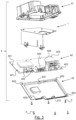
Fig. 3 ] illustrates an expandible view of a module assembly comprising the antenna offigure 1 , said module assembly further comprising an upper-casing, an electronic support and a cover, according to a non-limitative embodiment, - [
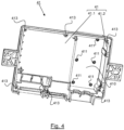
Fig. 4 ] illustrates a bottom view of the upper-casing of the module assembly offigure 3 , according to a non-limitative embodiment, - [
Fig. 5 ] illustrates the antenna offigure 1 orfigure 3 that is mounted into the upper-casing of the module assembly offigure 3 , according to a non-limitative embodiment, - [
Fig. 6 ] illustrates the antenna offigure 1 orfigure 3 that comes into contact with conductive portions of the electronic support offigure 2 via the at least one lanced-leg, according to a non-limitative embodiment, and - [
Fig. 7 ] illustrates the module assembly offigure 3 when all its elements are assembled altogether and that is closed by the cover offigure 3 , according to a non-limitative embodiment. - In the following description, well-known functions or constructions by the man skilled in the art are not described in detail since they would obscure the invention in unnecessary detail.
- The present invention relates to an
antenna 1 for a vehicle, saidantenna 1 being described in reference tofigures 1 to 7 , according to non-limitative embodiments. In a non-limitative embodiment, said vehicle is an automobile vehicle. The automobile vehicle is a motor vehicle or an electrical vehicle. In a non-limitative embodiment, theantenna 1 is a receiving antenna. It is configured to receive/send signals from/to a wireless network. - The
antenna 1 can be configured for use with any kind of technologies such as in non-limitative embodiments, such as Bluetooth™ or Bluetooth Low Energy™, Zigbee™, Ultra-wide Band, Wifi, and the like. - The
antenna 1 is part of amodule assembly 4 illustrated infigure 3 . In a non-limitative embodiment, themodule assembly 4 is part of atelematic control unit 5 of the automobile vehicle. - As illustrated in
figure 1 , theantenna 1 comprises : - a
body 10, and - a at least one
lanced leg 11. - In a non-limitative embodiment, the
body 10 has abending 100 that splits thebody 10 into two sub-parts 10.1 and 10.2. In a non-limitative embodiment, the two sub-parts 10.1 and 10.2 are roughly or totally perpendicular to each other. - In a non-limitative embodiment, the
body 10 comprises a plurality of mountingholes 101 to mount theantenna 11 to an upper-casing 41 of amodule assembly 4 described in the following. In a non-limitative example illustrated, there are fivemounting holes 101. - The
body 10 is made of a conductive material. In a non-limitative embodiment, it is composed of metal. The material is conductive in order to transmit to theelectronic support 42 the signals received from theantenna 1 . - In a non-limitative embodiment, the
antenna 1 comprises a plurality of lanced-legs 11. In a non-limitative variant of embodiment illustrated infigure 1 , it comprises two lanced-legs 11. This non-limitative variant of embodiment is taken as a non-limitative example in the following. - As illustrated in
figure 1 , the lanced-legs 11 extend from thebody 10 of theantenna 1. In particular, it extends from the sub-part 10.2 of thebody 10. They are made of the same conductive material as thebody 10. In a non-limitative embodiment, they are formed from a same sheet of material as thebody 10, here a sheet of metal. They are made of a conductive material. In a non-limitative embodiment, it is composed of metal. - The lanced-
legs 11 are configured to bend under a load compression F (illustrated infigure 5 ). They act as a spring under said load compression F. Under the load compression F, the lanced-legs 11 will deform. The lanced-legs 11 are configured without permanent deformation under the load compression F, so that the deformation is within the elastic limit of the material. In a non-limitative embodiment, the deformation of the lanced-legs 11 is of +/-0.3mm and above. It corresponds to dimensional variations of themodule assembly 4. Hence, when the load compression F is released, the lanced-legs 11 are in a preloaded state when all the elements of themodule assembly 4 are assembled altogether. They don't come back to their original position. Hence, theantenna 1 permits to accommodate the dimensional variations of themodule assembly 4. Theantenna 1 permits to always give a preload to theelectronic support 42 to ensure the contact by the lanced-legs 11 with it, even if it is vibrated or shocked. Moreover the lanced-legs 11 can operate in an operating temperature range of -40°Celsius to 80°Celsius. - In a non-limitative embodiment, the lanced-
legs 11 are configured to support a load compression F between 2 to 3 Newtons. It is the maximum load that the lanced-legs 11 can stand. It permits to ensure a proper contact between the lanced-legs 11 and theelectronic support 42 described in the following. - As illustrated in
figure 2 , the lanced-legs 11 comprise a z-bender part 110 and a lancedpart 111 that extends from the z-bender part 111. Thanks to this design, the lanced-legs 11 are flexible contrary to classical bending legs that are rigids. - As illustrated in
figure 2 , the z-bender part 110 extends from the sub-part 10.2 of thebody 10 of theantenna 1. The z-bender part 110 comprises afree space 1100 due to the lancing process where the material is cut and bent to produce a foot 111.1 for contact with aconductive portion 421 of theelectronic support 42. - The lanced
part 111 is configured to come into contact with a conductive portion 421 (described later) of anelectronic support 42 of themodule assembly 4. In particular, the lancedpart 111 has a foot 111.1 that is configured to come into contact with theconductive portion 421. - As illustrated in
figure 3 , theantenna 1 is part of amodule assembly 4. - The
module assembly 4 comprises : - the
antenna 1, - an upper-
casing 41, - an
electronic support 42, and - a
cover 43. - As illustrated in
figure 4 , the upper-casing 41 comprises two inner walls 41.1 and 41.2 that are roughly or totally perpendicular to each other. - The upper-
casing 41 is configured to receive theantenna 1. To this end, it comprises alodgment 410 as illustrated infigure 4 . The inner-wall 41.1 is configured to be in contact with the one sub-part 10.1 of thebody 10 of theantenna 1, and the other inner wall 41.2 is configured to be in contact with the other sub-part 10.2 of thebody 10 of theantenna 1 when theantenna 1 is placed in thelodgment 410. - The upper-
casing 41 is made of a plastic material. In a non-limitative example, the plastic material is PBT (polybutylene terephthalate). - As illustrated in
figure 6 , a load compression F can be applied on the upper-casing 41 when theantenna 1 is mounted within the upper-casing 41. This later permits to maintain the lanced-legs 11 into position so that they don't bounce back like a spring into their initial position, that is their relaxed position, where there is no load compression F. The upper-casing 41 holds theantenna 1 into position onto theelectronic support 42. The lanced-legs 11 are in the expected preload (2-3 Newtons in the non-limitative example) when the upper-casing 41 holds theantenna 1 into position. - Depending on the manufacturing process, there are dimensional variations of the module assembly 4 (coming from one or a plurality of elements of said module assembly 4). In a non-limitative embodiment, the dimensional variations are between +- 0.3millimeters (0.6mm in total) and above.
- As illustrated in
figure 4 , in a non-limitative embodiment, the upper-casing 41 further comprises rivets 411 (illustrated infigure 4 ) configured to maintain theantenna 1 into contact with said upper-casing 41 and to fix it to said upper-casing 41. In a non-limitative example, there are fiverivets 411. - As illustrated in
figure 4 , in a non-limitative embodiment, the upper-casing 41 further comprises first fixingholes 413 along its four edges. Said first fixingholes 413 are configured to each receive a screw 5 (illustrated infigures 3 or7 ). In a non-limitative example, there are six first fixing holes 413. - In a non-limitative embodiment, the
electronic support 42 is a printed circuit electronic circuit board, referred to as PCBA. The PCBA compriseselectronic components 428. To simplify the figures, only oneelectronic component 428 has been illustrated. Theelectronic support 42 is configured to provide an electric current (not illustrated) to theantenna 1 via the contact between itsconductive portion 421 and the lanced-legs 11 of theantenna 1. The PCBA comprises at least oneconductive portion 421, also called aconductive contact 421, configured to be in contact with the lancedpart 111 of the at least one lanced-leg 11 of theantenna 1. - In a non-limitative embodiment, the
electronic support 42 comprises a plurality ofconductive portions 421. In a non-limitative example illustrated, it comprises twoconductive portions 421. Theconductive portions 421 areconductive contact 421 for the lanced-legs 11, in particular for their lancedparts 111 that sit on saidconductive contacts 421. - In a non-limitative embodiment, the
electronic support 42 further comprises second fixing holes 423 (illustrated infigure 2 and5 ) along its perimeter configured to each receive ascrew 5. In a non-limitative example, there are six second fixing holes 423. For clarity of thefigure 2 , only two second fixing holes 423 have been referenced. - As illustrated in
figure 3 , in non-limitative embodiments, theelectronic support 42 further comprises a plurality ofexternal connectors antenna connectors 422 for connecting theantenna 1 to the TCU. - As illustrated in
figure 6 , thecover 43 is configured to close themodule assembly 4. Thecover 43 comprises third fixing holes 433 (illustrated infigure 1 ) along its edges configured to each receive ascrew 5. In a non-limitative example, there are six third fixing holes 433. - The
elements module assembly 4 are assembled as follows. - Firstly, as illustrated in
figure 5 , theantenna 1 is placed in thelodgment 410 of the upper-casing 41. Therivets 411 of the upper-casing 41 are inserted into the mountingholes 101 of theantenna 1 and theantenna 1 is riveted to the upper-casing 41 so that one sub-part 10.1 of itsbody 10 is in contact with one inner wall 41.1 of the upper-casing 41 and the other sub-part 10.2 of itsbody 10 is in contact with the other inner wall 41.2 of the upper-casing 41. - Secondly, the
antenna 1 along the upper-casing 41 is assembled to theelectronic support 42. To this end, the lanced-legs 11 of theantenna 1, in particular their lancedparts 111, are put into contact with theconductive portions 421 of theelectronic support 42. They sit onto theconductive portions 421.
As illustrated infigure 6 , the sub-part 10.1 of thebody 10 of theantenna 1 is roughly or totally parallel to theelectronic support 42, whereas the sub-part 10.2 of thebody 10 is roughly or totally perpendicular to theelectronic support 42. - Then, for the assembly, a load compression F (illustrated in
figure 6 ) is applied onto the upper-casing 41 andantenna 1 assembly. Infigure 6 , only theantenna 1 with theelectronic support 42 has been illustrated. The lanced-legs 11 deform themselves and bend under the load compression F so that the contact with theconductive portions 421 is safely established. The lanced-legs 11 are maintained into this position by any tool. In other words, the lanced-legs 11 of theantenna 1 compress themselves so that a preload is exerted on theelectronic support 42 when the lanced-legs 11 are in contact with theconductive portion 421 of theelectronic support 42. The lanced-legs 11 are in a preload state (which holds theantenna 1 in its position) so that they don't bounce back. - Thirdly, as illustrated in
figure 7 , thecover 43 is assembled to the upper-casing 41 by means of thescrews 5 that are inserted into the third fixing holes 431 of thecover 43, the second fixing holes 421 of theelectronic support 42 and then the first fixingholes 411 of the upper-casing 41. Thescrews 5 are screwed into the first fixingholes 411 of the upper-casing 41. - The
module assembly 4 is then assembled. The load compression F can then be suppressed. - Fourthly, the load compression F is released. When the load compression F is released, the lanced-
legs 11 stay in their preload state. Thus, theantenna 1 remains in contact with theelectronic support 42 via its lanced-legs 11. - It is to be understood that the present invention is not limited to the aforementioned embodiments and variations and modifications may be made without departing from the scope of the invention. In this respect, the following remarks are made. All statements herein reciting principles, aspects, and embodiments of the invention, as well as specific examples thereof, are intended to encompass equivalents thereof. In a non-limitative embodiment, the
module assembly 4 can be integrated in an emergency call box. In this case, theantenna 1 is configured to receive a signal from the environment of the automobile vehicle and send it to the TCU. - Hence, some embodiments of the invention may comprise one or a plurality of the following advantages:
- it permits to absorb the dimensional variation (around 0.6mm total amount) of the upper-
casing 41 andantenna 1 assembly towards theelectronic support 42, contrary to the prior art with rigids legs, - as the lanced-
legs 11 extend from thebody 10 of theantenna 1 and are formed from a peripheral part of the sheet of metal used for theantenna 1, there are no wastage of material, contrary to a process where legs are fabricated from the center of the sheet of metal leading to a free space in the center of the sheet of metal, - it permits to have an easier manufacturing process for the
antenna 1, as the lanced-legs 11 extend from thebody 10 of theantenna 1, contrary to some prior arts where theantenna 1 has 2 or 3 parts assemblies that have to be assembled to the body instead of a leg, - the fact that the
body 10 of theantenna 1 is in two sub-parts 10.1 and 10.2 perpendicular to each other permits to gain some space, compared to a solution where the body of the antenna is in one part and flat and entirely parallel to the electronic support, - it permits to convert the
antenna 1 into a kind of spring by the lancing. It permits to replace a solution where the conductive portions of the electronic support are about twenty and made of rubbers that takes the dimensional variation of the assembly, and where the more the dimensional variation is, the more the rubbers compress under the antenna compression. The solution reduces additional process's cost as it doesn't need to attached any contact foams onto the electronic support contrary to the solution with the rubbers, - the lanced-
legs 11 can retain their resilient property even at extreme degrees such as minus 40° Celsius to plus 80° Celsius, contrary to rubbers attached to the electronic support that lose their resilient property as they freeze under minus temperatures and therefore stay rigids and therefore can't be compressed anymore and thereby lose the electrical contact with the conductive portions of an electrical support. The resilient property is the ability to spring back into shape, and this resilient property permits to deform the lanced-legs 11 and exert a preload onto theconductive portions 421 of theelectronic support 42, - the solution with the lanced-
legs 11 is more robust than a solution where springs are used and attached by welding to the electronic support and to the body of an antenna.
Claims (10)
- Antenna (1) for a vehicle (2), said antenna (1) comprising a body (10), wherein said antenna (1) further comprises at least one lanced leg (11) that extends from said body (10) and that is configured to bend under a load compression (F), said at least one lanced leg (11) comprising a z-bender part (110) and a lanced part (111) that extends from the z-bender part (111) and that is configured to come into contact with a conductive portion (421) of an electronic support (42).
- Antenna (1) according to claim 1, wherein said antenna (1) comprises a plurality of lanced-legs (11).
- Antenna (1) according to any of the preceding claims, wherein said body (10) has a bending (100) that splits the body (10) into two sub-parts (10.1, 10.2).
- Antenna (1) according to the preceding claim, wherein said two sub-parts (10.1, 10.2) are perpendicular to each other.
- Antenna (1) according to any of the preceding claims, wherein said body (10) comprises a plurality of mounting holes (101) to mount the antenna (11) to an up-casing (41) of a module assembly (4).
- Antenna (1) according to any of the preceding claims, wherein said at least one lanced leg (11) is configured to bend without permanent deformation under said load compression (F).
- Antenna (1) according to any of the preceding claims, wherein said load compression (F) is between 2 and 3 Newtons.
- Module assembly (4) for a vehicle (2), wherein said module assembly (4) comprises :- an antenna (1) as claimed in any preceding claims,- an upper-casing (41) where said antenna (1) is to be mounted,- an electronic support (42) that comprises at least one conductive portion (421) configured to be in contact with the lanced part (111) of said at least one lanced-leg (11) of the antenna (1),- a cover (43) that is configured to close the module assembly (4).
- Module assembly (4) according to the preceding claim, wherein said upper-casing (41) is made of a conductive material.
- Telematic Control Unit (5) comprising a module assembly (4) as claimed in claim 8 or claim 9.
Priority Applications (2)
| Application Number | Priority Date | Filing Date | Title |
|---|---|---|---|
| EP22212015.6A EP4383448A1 (en) | 2022-12-07 | 2022-12-07 | Antenna for a telematic control unit of a vehicle |
| PCT/EP2023/082878 WO2024120844A1 (en) | 2022-12-07 | 2023-11-23 | Antenna for a telematic control unit of a vehicle |
Applications Claiming Priority (1)
| Application Number | Priority Date | Filing Date | Title |
|---|---|---|---|
| EP22212015.6A EP4383448A1 (en) | 2022-12-07 | 2022-12-07 | Antenna for a telematic control unit of a vehicle |
Publications (1)
| Publication Number | Publication Date |
|---|---|
| EP4383448A1 true EP4383448A1 (en) | 2024-06-12 |
Family
ID=84440028
Family Applications (1)
| Application Number | Title | Priority Date | Filing Date |
|---|---|---|---|
| EP22212015.6A Pending EP4383448A1 (en) | 2022-12-07 | 2022-12-07 | Antenna for a telematic control unit of a vehicle |
Country Status (2)
| Country | Link |
|---|---|
| EP (1) | EP4383448A1 (en) |
| WO (1) | WO2024120844A1 (en) |
Citations (3)
| Publication number | Priority date | Publication date | Assignee | Title |
|---|---|---|---|---|
| US20030063030A1 (en) * | 2001-09-28 | 2003-04-03 | Vladimir Stoiljkovic | Integral antenna and radio system |
| KR100701868B1 (en) * | 2006-03-09 | 2007-04-03 | 주식회사 스카이크로스코리아 | Built-in antenna for mobile terminal |
| CN203218439U (en) * | 2013-02-28 | 2013-09-25 | 青岛海信移动通信技术股份有限公司 | Portable mobile terminal used antenna and portable mobile terminal |
-
2022
- 2022-12-07 EP EP22212015.6A patent/EP4383448A1/en active Pending
-
2023
- 2023-11-23 WO PCT/EP2023/082878 patent/WO2024120844A1/en not_active Ceased
Patent Citations (3)
| Publication number | Priority date | Publication date | Assignee | Title |
|---|---|---|---|---|
| US20030063030A1 (en) * | 2001-09-28 | 2003-04-03 | Vladimir Stoiljkovic | Integral antenna and radio system |
| KR100701868B1 (en) * | 2006-03-09 | 2007-04-03 | 주식회사 스카이크로스코리아 | Built-in antenna for mobile terminal |
| CN203218439U (en) * | 2013-02-28 | 2013-09-25 | 青岛海信移动通信技术股份有限公司 | Portable mobile terminal used antenna and portable mobile terminal |
Also Published As
| Publication number | Publication date |
|---|---|
| WO2024120844A1 (en) | 2024-06-13 |
Similar Documents
| Publication | Publication Date | Title |
|---|---|---|
| CN102246610B (en) | Electric equipment | |
| US8384604B2 (en) | Integrated antenna and EMI shielding support member for portable communications terminals | |
| JP5685209B2 (en) | Battery holder | |
| KR950009774B1 (en) | Housing assembly and assembly method | |
| WO2008027664A2 (en) | Low-profile assemblies for providing board level emi shielding for electrical components on opposite sides of printed circuit boards | |
| CN110301021B (en) | Power storage unit | |
| CN102762415B (en) | safety equipment | |
| CN105959887B (en) | Loudspeaker module | |
| EP4383448A1 (en) | Antenna for a telematic control unit of a vehicle | |
| US4196467A (en) | Electronic system housing structure, particularly for automotive environments | |
| EP1633015B1 (en) | Sealing member and sealing structure of electronic circuit unit | |
| US7396238B2 (en) | Battery contact system and wireless terminal having the same | |
| GB2385992A (en) | Antenna installation structure | |
| WO2020239045A1 (en) | A heating device | |
| JP5201751B2 (en) | Electronics | |
| CN112398990B (en) | Sound production device and mobile phone thereof | |
| GB2540864A (en) | Electronic assembly having alignable stacked circuit boards | |
| JP5165602B2 (en) | Antenna holding structure and antenna device | |
| US20170265303A1 (en) | Electrolytic capacitor retention device | |
| US7443072B2 (en) | Brush card for window lift motors | |
| US20210289627A1 (en) | Module assembly mounted on headlining of vehicle | |
| JP2019012942A (en) | Antenna device and antenna mounting device | |
| CN219498011U (en) | Battery mounting device and electronic equipment | |
| CN111963531B (en) | Electronic component assembly and assembly thereof with adherend and method for mounting electronic component | |
| KR100676104B1 (en) | Condenser microphone socket for SMD |
Legal Events
| Date | Code | Title | Description |
|---|---|---|---|
| PUAI | Public reference made under article 153(3) epc to a published international application that has entered the european phase |
Free format text: ORIGINAL CODE: 0009012 |
|
| STAA | Information on the status of an ep patent application or granted ep patent |
Free format text: STATUS: THE APPLICATION HAS BEEN PUBLISHED |
|
| AK | Designated contracting states |
Kind code of ref document: A1 Designated state(s): AL AT BE BG CH CY CZ DE DK EE ES FI FR GB GR HR HU IE IS IT LI LT LU LV MC ME MK MT NL NO PL PT RO RS SE SI SK SM TR |
|
| STAA | Information on the status of an ep patent application or granted ep patent |
Free format text: STATUS: REQUEST FOR EXAMINATION WAS MADE |
|
| 17P | Request for examination filed |
Effective date: 20241212 |