EP4383441A1 - Electrodes configuration in a battery - Google Patents
Electrodes configuration in a battery Download PDFInfo
- Publication number
- EP4383441A1 EP4383441A1 EP22306820.6A EP22306820A EP4383441A1 EP 4383441 A1 EP4383441 A1 EP 4383441A1 EP 22306820 A EP22306820 A EP 22306820A EP 4383441 A1 EP4383441 A1 EP 4383441A1
- Authority
- EP
- European Patent Office
- Prior art keywords
- anode
- cathode
- foil
- coating layer
- tab
- Prior art date
- Legal status (The legal status is an assumption and is not a legal conclusion. Google has not performed a legal analysis and makes no representation as to the accuracy of the status listed.)
- Pending
Links
- 239000011888 foil Substances 0.000 claims abstract description 56
- 239000011247 coating layer Substances 0.000 claims abstract description 53
- 238000009413 insulation Methods 0.000 claims abstract description 18
- 238000010292 electrical insulation Methods 0.000 claims abstract description 10
- 238000000926 separation method Methods 0.000 claims description 4
- 238000004519 manufacturing process Methods 0.000 description 6
- HBBGRARXTFLTSG-UHFFFAOYSA-N Lithium ion Chemical compound [Li+] HBBGRARXTFLTSG-UHFFFAOYSA-N 0.000 description 3
- 229910001416 lithium ion Inorganic materials 0.000 description 3
- 239000000463 material Substances 0.000 description 3
- PXHVJJICTQNCMI-UHFFFAOYSA-N Nickel Chemical compound [Ni] PXHVJJICTQNCMI-UHFFFAOYSA-N 0.000 description 2
- 239000000654 additive Substances 0.000 description 2
- 239000004411 aluminium Substances 0.000 description 2
- XAGFODPZIPBFFR-UHFFFAOYSA-N aluminium Chemical compound [Al] XAGFODPZIPBFFR-UHFFFAOYSA-N 0.000 description 2
- 229910052782 aluminium Inorganic materials 0.000 description 2
- OKTJSMMVPCPJKN-UHFFFAOYSA-N Carbon Chemical compound [C] OKTJSMMVPCPJKN-UHFFFAOYSA-N 0.000 description 1
- RYGMFSIKBFXOCR-UHFFFAOYSA-N Copper Chemical compound [Cu] RYGMFSIKBFXOCR-UHFFFAOYSA-N 0.000 description 1
- 230000002411 adverse Effects 0.000 description 1
- 239000011230 binding agent Substances 0.000 description 1
- 239000000919 ceramic Substances 0.000 description 1
- 238000000576 coating method Methods 0.000 description 1
- 239000010941 cobalt Substances 0.000 description 1
- 229910017052 cobalt Inorganic materials 0.000 description 1
- GUTLYIVDDKVIGB-UHFFFAOYSA-N cobalt atom Chemical compound [Co] GUTLYIVDDKVIGB-UHFFFAOYSA-N 0.000 description 1
- 239000004020 conductor Substances 0.000 description 1
- 239000010949 copper Substances 0.000 description 1
- 229910052802 copper Inorganic materials 0.000 description 1
- 238000005520 cutting process Methods 0.000 description 1
- 230000002708 enhancing effect Effects 0.000 description 1
- WPBNNNQJVZRUHP-UHFFFAOYSA-L manganese(2+);methyl n-[[2-(methoxycarbonylcarbamothioylamino)phenyl]carbamothioyl]carbamate;n-[2-(sulfidocarbothioylamino)ethyl]carbamodithioate Chemical compound [Mn+2].[S-]C(=S)NCCNC([S-])=S.COC(=O)NC(=S)NC1=CC=CC=C1NC(=S)NC(=O)OC WPBNNNQJVZRUHP-UHFFFAOYSA-L 0.000 description 1
- 238000000034 method Methods 0.000 description 1
- 238000012986 modification Methods 0.000 description 1
- 230000004048 modification Effects 0.000 description 1
- 229910052759 nickel Inorganic materials 0.000 description 1
- 239000000615 nonconductor Substances 0.000 description 1
- 239000002985 plastic film Substances 0.000 description 1
- 229920006255 plastic film Polymers 0.000 description 1
Images

Classifications
-
- H—ELECTRICITY
- H01—ELECTRIC ELEMENTS
- H01M—PROCESSES OR MEANS, e.g. BATTERIES, FOR THE DIRECT CONVERSION OF CHEMICAL ENERGY INTO ELECTRICAL ENERGY
- H01M50/00—Constructional details or processes of manufacture of the non-active parts of electrochemical cells other than fuel cells, e.g. hybrid cells
- H01M50/50—Current conducting connections for cells or batteries
- H01M50/531—Electrode connections inside a battery casing
- H01M50/533—Electrode connections inside a battery casing characterised by the shape of the leads or tabs
-
- H—ELECTRICITY
- H01—ELECTRIC ELEMENTS
- H01M—PROCESSES OR MEANS, e.g. BATTERIES, FOR THE DIRECT CONVERSION OF CHEMICAL ENERGY INTO ELECTRICAL ENERGY
- H01M4/00—Electrodes
- H01M4/02—Electrodes composed of, or comprising, active material
- H01M4/64—Carriers or collectors
- H01M4/70—Carriers or collectors characterised by shape or form
-
- H—ELECTRICITY
- H01—ELECTRIC ELEMENTS
- H01M—PROCESSES OR MEANS, e.g. BATTERIES, FOR THE DIRECT CONVERSION OF CHEMICAL ENERGY INTO ELECTRICAL ENERGY
- H01M50/00—Constructional details or processes of manufacture of the non-active parts of electrochemical cells other than fuel cells, e.g. hybrid cells
- H01M50/50—Current conducting connections for cells or batteries
- H01M50/572—Means for preventing undesired use or discharge
- H01M50/584—Means for preventing undesired use or discharge for preventing incorrect connections inside or outside the batteries
- H01M50/586—Means for preventing undesired use or discharge for preventing incorrect connections inside or outside the batteries inside the batteries, e.g. incorrect connections of electrodes
-
- H—ELECTRICITY
- H01—ELECTRIC ELEMENTS
- H01M—PROCESSES OR MEANS, e.g. BATTERIES, FOR THE DIRECT CONVERSION OF CHEMICAL ENERGY INTO ELECTRICAL ENERGY
- H01M50/00—Constructional details or processes of manufacture of the non-active parts of electrochemical cells other than fuel cells, e.g. hybrid cells
- H01M50/50—Current conducting connections for cells or batteries
- H01M50/572—Means for preventing undesired use or discharge
- H01M50/584—Means for preventing undesired use or discharge for preventing incorrect connections inside or outside the batteries
- H01M50/59—Means for preventing undesired use or discharge for preventing incorrect connections inside or outside the batteries characterised by the protection means
- H01M50/591—Covers
-
- H—ELECTRICITY
- H01—ELECTRIC ELEMENTS
- H01M—PROCESSES OR MEANS, e.g. BATTERIES, FOR THE DIRECT CONVERSION OF CHEMICAL ENERGY INTO ELECTRICAL ENERGY
- H01M50/00—Constructional details or processes of manufacture of the non-active parts of electrochemical cells other than fuel cells, e.g. hybrid cells
- H01M50/50—Current conducting connections for cells or batteries
- H01M50/572—Means for preventing undesired use or discharge
- H01M50/584—Means for preventing undesired use or discharge for preventing incorrect connections inside or outside the batteries
- H01M50/59—Means for preventing undesired use or discharge for preventing incorrect connections inside or outside the batteries characterised by the protection means
- H01M50/593—Spacers; Insulating plates
-
- H—ELECTRICITY
- H01—ELECTRIC ELEMENTS
- H01M—PROCESSES OR MEANS, e.g. BATTERIES, FOR THE DIRECT CONVERSION OF CHEMICAL ENERGY INTO ELECTRICAL ENERGY
- H01M50/00—Constructional details or processes of manufacture of the non-active parts of electrochemical cells other than fuel cells, e.g. hybrid cells
- H01M50/50—Current conducting connections for cells or batteries
- H01M50/572—Means for preventing undesired use or discharge
- H01M50/584—Means for preventing undesired use or discharge for preventing incorrect connections inside or outside the batteries
- H01M50/59—Means for preventing undesired use or discharge for preventing incorrect connections inside or outside the batteries characterised by the protection means
- H01M50/595—Tapes
-
- Y—GENERAL TAGGING OF NEW TECHNOLOGICAL DEVELOPMENTS; GENERAL TAGGING OF CROSS-SECTIONAL TECHNOLOGIES SPANNING OVER SEVERAL SECTIONS OF THE IPC; TECHNICAL SUBJECTS COVERED BY FORMER USPC CROSS-REFERENCE ART COLLECTIONS [XRACs] AND DIGESTS
- Y02—TECHNOLOGIES OR APPLICATIONS FOR MITIGATION OR ADAPTATION AGAINST CLIMATE CHANGE
- Y02E—REDUCTION OF GREENHOUSE GAS [GHG] EMISSIONS, RELATED TO ENERGY GENERATION, TRANSMISSION OR DISTRIBUTION
- Y02E60/00—Enabling technologies; Technologies with a potential or indirect contribution to GHG emissions mitigation
- Y02E60/10—Energy storage using batteries
Definitions
- the present invention concerns the technical field of electric batteries, in particular lithium-ion batteries used, for instance, to power the traction chain of electric or hybrid vehicles.
- the invention is related to an innovative electrodes configuration which improves the electrical insulation between a cathode and an anode of such a battery.
- Lithium-ion batteries have a stack architecture comprising of a plurality of anodes (negative electrodes) and cathodes (positive electrodes) which are composed of foils or sheets stacked against each other and separated by a separation sheet (also known as a separator).
- Each cathode foil also called current collector and made for instance with aluminium
- each anode foil is covered with an anode coating layer.
- These coating layers are usually made with non-insulated electrical materials.
- cathode foils are generally slightly smaller than anode foils. Furthermore, each cathode and each anode are extended with a connecting tab consisting of a small outgrowth beyond the foil plan. These tabs are flexible and are used to electrically connect the electrodes to external terminals of the battery in order to recover the electrical energy. In addition, during the manufacturing process of the different foil stacks, the positioning of electrodes and separators can be imperfect.
- one purpose of this invention is to improve the structure of an electrodes stack battery by providing an effective, reliable, economical and easy to implement solution that enhances the insulation between the cathode tabs and the adjacent anodes without adversely affecting the performance of the battery.
- the invention provides a battery comprising at least a cathode and an anode, the anode comprising a foil covered by an anode coating layer, the cathode comprising a foil facing the anode foil and a flexible tab which projects beyond the cathode foil along a vertical direction parallel to the cathode foil plan, said cathode tab being covered with an electrical insulation cover.
- the anode comprises an extension of the anode coating layer beyond the anode foil along the vertical direction, said extension being designed so that the cathode tab insulation cover overlaps the extremity of said extension of the anode coating layer.
- the cathode foil is covered by a cathode coating layer and the cathode presents a gap band without insulation between the cathode coating layer and the cathode tab insulation cover.
- the extension of the anode coating layer is located only in the vicinity of the cathode tab. According to one embodiment, the extension of the anode coating layer is applied on both sides of the anode foil. According to one embodiment, the anode foil also comprises an extension having dimensions similar to the extension of the anode coating layer.
- the anode foil and the cathode foil are separated by a separation sheet.
- the anode also comprises a tab which projects beyond the anode foil along the vertical direction and which is offset from the cathode tab.
- the cathode tab and the anode tab are used for the electrical connection of the battery.
- the battery comprises a plurality of such cathodes and a plurality of such anodes which are alternately arranged and separated by a plurality of separating sheets.
- a battery comprises at least one cathode in the form of a foil 10, made of aluminium for example, surrounded on each side by a cathode coating layer 11, containing nickel, manganese, cobalt and additives, for instance.
- the battery also comprises at least one anode in the form of a foil 20, made for example of copper, surrounded on each side by an anode coating layer 21, containing fine graphite powder and additives, for example.
- the anode 20 and cathode 10 are placed against each other and are separated by a separation sheet 30, also called a separator, which, for instance, can be a plastic film.
- the separator 30 must be very thin and porous to allow a free passage of lithium ions between the cathode and anode and is thus fragile.
- the anode 20 and cathode 10 are flat and rectangular and the anode 20 is typically a few millimeters wider and higher than the cathode 10, to fully cover the cathode 10 up at its every edge.
- An electrode stack battery is usually composed of a stack of such electrodes foils and thus comprises a plurality of cathodes 10 and a plurality of anodes 20 which are alternately arranged and separated by a plurality of separators 30.
- Figure 1 shows a stack of two anodes and two cathodes with their respective separators 30 positioned between each.
- the dimensions of the cathode and anode foils 10, 20 are approximately 200 mm wide and 80-100 mm high.
- the total thickness of the cathode 10 and anode 20, including their respective coating layers 11, 21, is approximately 0.2 mm.
- the separator 30 is somewhat wider and higher than the anode 20 and has a thickness of about 10-15 ⁇ m (micron meters).
- a battery can for instance comprise a stack of several dozens of anodes and cathodes.
- the cathode 10 comprises a flexible tab 14 which projects beyond an upper horizontal straight edge 15 of the cathode foil 10 along a vertical direction X parallel to the cathode foil plan.
- This cathode tab 14 is only present on one section of the upper edge 15 of the cathode 10.
- the cathode tab 14 is, for instance, 40-50 mm wide and around 20 mm high.
- the anode 20 comprises a flexible tab 24 which projects beyond an upper straight horizontal edge 25 of the anode foil 20 along the vertical direction X.
- This anode tab 24 is only present on one section of the upper edge of the anode 20.
- the anode tab 24 is, for instance, 40-50 mm wide and around 20 mm high, and is of course offset from the cathode tab 14 along the upper edge 25.
- These tabs 14, 24 are used to electrically connect the electrodes 10, 20 to external terminals of the battery in order to recover the electrical energy.
- the tabs 14, 24 must be flexible to facilitate these connections.
- the cathode tab 14 can come too close to the anode coating layer 21 (made of conductive materials) which could then induce a short circuit between the cathode and anode in case of loss of the separator 30 locally.
- an electrical insulation cover 12 can be added on each side of the cathode tab 14 to prevent electrical contact between the cathode tab 14 and an adjacent anode coating layer 21, even in case of loss of the separator locally.
- the electrical insulation cover 12 can be made with, but not limited to, ceramics and binder. However, there always remains a physical gap band 13 between this insulation cover 12 of the cathode tab 14 and the coating layer 11 of the cathode foil 10, leaving the metallic cathode foil without protection.
- this gap band 13 exists since the tab electrical insulation cover 12 cannot be applied too broadly. Indeed, having an insulation cover 12 that is too extensive may encroach on the cathode foil coating layer 11 and thus reduce the effective useful area of the cathode 10, which would reduce the global efficiency of the battery. Furthermore, the size of the gap band 13 can vary due to unavoidable small disparities in electrode dimensions and/or linearity, during the manufacturing process of the electrodes. Controlling the manufacturing process with higher precision to constantly ensure a stable minimal gap would be costly and challenging, especially in a mass production scenario.
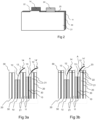
- Figures 3a and 3b show two similar sectional views with details of an upper part of the battery along a vertical plan perpendicular to the vertical foils plane, at a point where cathode tabs 14 are present.
- Figure 3a represents a battery according to the state of the art
- Figure 3b represents a battery including the invention.
- FIG 3a shows two examples of cathode tabs 14, 14' each with an insulating cover 12 and a gap band 13.
- the cathode tab 14 on the left of Figure 3a , when the flexible cathode tab 14 tilts, it can come into contact with the upper edge of the adjacent anode coating layer 21 through its insulating cover 12. The tab 14 is then protected by its insulating cover 12 which overlaps the extremity of the anode coating layer 21 when the cathode tab 14 tilts, so that, in this case, the double electrical insulation between cathode 10 and anode 20 is secured by the insulating cover 12 and the separator 30.
- the cathode tab 14' is somewhat higher than the tab 14, as for instance the cathode 10 is also a little higher.
- its gap band 13 can come into contact with the upper edge of the adjacent anode coating layer 21 with the separator 30 for only insulation between them (see point A), as the tab 14' is not protected anymore by its insulating cover 12 which does not overlap the extremity of the anode coating layer 21.
- a short circuit can occur between cathode 10 and anode 20 at point A, if ever there is any damage of the separator 30 locally.
- the present invention proposes to increase the size of each anode coating layer 21 so that, in all cases, the cathode tab 14 is protected by its insulating cover 12 between the cathode tab 14 and the extremity of the adjacent anode coating layer 21, thus always providing a double insulation with insulating cover 12 plus separator 30.
- the battery comprises an extension 22 of the anode coating layer 21 along the vertical direction X, this extension 22 being designed so that the cathode tab insulation cover 12 is always overlapping the extremity of said extension 22 of the anode coating layer 21 when the cathode tab 14 tilts.
- this extension 22 being designed so that the cathode tab insulation cover 12 is always overlapping the extremity of said extension 22 of the anode coating layer 21 when the cathode tab 14 tilts.
- the cathode tab 14' comes into to contact with the extension 22 of the anode coating layer 21 through its insulating cover 12, avoiding any risk of short circuit, despite the size of gap band 13.
- the extremity of the anode coating layer 21 will always cross the cathode tab 14 on the insulation cover 12 beyond the gap band 13.
- the extension 22 is made with the same material of the anode coating layer 21 and is manufactured directly during the cutting process of the anode coating layer 21. Moreover, in a preferred manufacturing process, the anode foil 20 is first plated with its coating layers 21 on each side, then this assembly is cut to the right dimensions for the battery. It means that in this case, the creation of an extension 22 of the anode coating layer 21 also creates a corresponding extension 23 of the anode foil 20 (see figure 3b ), this extension 23 having dimensions similar to the extension 22 of the anode coating layer 21.
- this process ensures a cheap and simple solution to manufacture and implement the invention.
- Figure 2 represents a preferred embodiment of the invention. It shows one anode coating layer 21 with an extension 22 above its upper horizontal edge 25.
- the anode coating layer 21 covers the anode foil from which only the anode tab 24 can be seen (as the anode foil 20 and its coating layer 21 on the other side are of course hidden on Figure 2 ).
- the extension 22 does not extend along the whole upper edge 25 of the anode coating layer 21, but instead is limited to the section of the anode coating layer 21 which is in the vicinity of the corresponding cathode tab 14.
- the height of the extension 22 is about 1 mm.
- the invention thereby provides a solution for the electrode stack configuration of a battery, which always guarantees insulation between anodes and cathodes without risk of any short-circuit, thus enhancing the global reliability of the battery. It also avoids a costly insulation coating process as it allows a greater margin in the gap band between the cathode coating layer and the cathode tab insulation cover.
Landscapes
- Chemical & Material Sciences (AREA)
- Chemical Kinetics & Catalysis (AREA)
- Electrochemistry (AREA)
- General Chemical & Material Sciences (AREA)
- Connection Of Batteries Or Terminals (AREA)
- Primary Cells (AREA)
Abstract
The invention relates to a battery comprising at least a cathode (10) and an anode (20), the anode comprising a foil (20) covered by an anode coating layer (21), the cathode comprising a foil (10) facing the anode foil (20) and a flexible tab (14) which projects beyond the cathode foil (10) along a vertical direction (X) parallel to the cathode foil plan. Said cathode tab (14) is covered with an electrical insulation cover (12). The anode comprises an extension (22) of the coating layer (21) beyond the anode foil (20), along the vertical direction (X). Said extension (22) is designed so that the cathode tab insulation cover (12) overlaps the extremity of said extension (22) of the anode coating layer (21).
Description
- The present invention concerns the technical field of electric batteries, in particular lithium-ion batteries used, for instance, to power the traction chain of electric or hybrid vehicles.
- More specifically, the invention is related to an innovative electrodes configuration which improves the electrical insulation between a cathode and an anode of such a battery.
- Some Lithium-ion batteries have a stack architecture comprising of a plurality of anodes (negative electrodes) and cathodes (positive electrodes) which are composed of foils or sheets stacked against each other and separated by a separation sheet (also known as a separator). Each cathode foil (also called current collector and made for instance with aluminium) is covered with a cathode coating layer and each anode foil is covered with an anode coating layer. These coating layers are usually made with non-insulated electrical materials.
- It is known that, in this type of battery architecture, cathode foils are generally slightly smaller than anode foils. Furthermore, each cathode and each anode are extended with a connecting tab consisting of a small outgrowth beyond the foil plan. These tabs are flexible and are used to electrically connect the electrodes to external terminals of the battery in order to recover the electrical energy. In addition, during the manufacturing process of the different foil stacks, the positioning of electrodes and separators can be imperfect.
- As a result of the above elements, once the battery is assembled, there is a risk that the flexible tab of some cathodes will not be sufficiently far from the short-circuit with the adjacent anodes, despite the presence of the separator. Even if the separator in itself is an electrical insulator, it may not be sufficient for preventing a short circuit around the particular tab region, because this cathode tab region has a much higher possibility of short-circuit risk, as the cathode tab can cross over the border/edge of the anode. Moreover, the chances for the separator to get damaged, torn or punctured must be taken into account, due in particular to its thinness. This has indeed the potential to cause a short-circuit between a cathode tab and an anode. Using a thicker separator could reduce the efficiency of the battery and be more expensive.
- It is already known that, to avoid this problem, an electrical insulation cover can be added on each cathode tab to prevent any electrical contact between the cathode tab and adjacent anodes and provide a double insulation between the cathode tab and the anode upper edge. However, a physical gap between this electrical insulation cover of the cathode tab and the coating layer of the cathode foil always remains. This physical gap leaves the metallic cathode foil without protection.
- Therefore, one purpose of this invention is to improve the structure of an electrodes stack battery by providing an effective, reliable, economical and easy to implement solution that enhances the insulation between the cathode tabs and the adjacent anodes without adversely affecting the performance of the battery.
- In order to achieve the above purpose, the invention provides a battery comprising at least a cathode and an anode, the anode comprising a foil covered by an anode coating layer, the cathode comprising a foil facing the anode foil and a flexible tab which projects beyond the cathode foil along a vertical direction parallel to the cathode foil plan, said cathode tab being covered with an electrical insulation cover. The anode comprises an extension of the anode coating layer beyond the anode foil along the vertical direction, said extension being designed so that the cathode tab insulation cover overlaps the extremity of said extension of the anode coating layer.
- According to one embodiment, the cathode foil is covered by a cathode coating layer and the cathode presents a gap band without insulation between the cathode coating layer and the cathode tab insulation cover.
- According to one embodiment, the extension of the anode coating layer is located only in the vicinity of the cathode tab. According to one embodiment, the extension of the anode coating layer is applied on both sides of the anode foil. According to one embodiment, the anode foil also comprises an extension having dimensions similar to the extension of the anode coating layer.
- According to one embodiment, the anode foil and the cathode foil are separated by a separation sheet.
- According to one embodiment, the anode also comprises a tab which projects beyond the anode foil along the vertical direction and which is offset from the cathode tab. The cathode tab and the anode tab are used for the electrical connection of the battery.
- According to one embodiment, the battery comprises a plurality of such cathodes and a plurality of such anodes which are alternately arranged and separated by a plurality of separating sheets.
- Further features and advantages of the invention will become apparent from the following description, with reference to the annexed figures, wherein:
-
figure 1 shows a simplified and schematic exploded view of part of a battery according to the prior art; -
figure 2 represents an implementation detail of one embodiment of the invention; -
figure 3a and figure 3b show a sectional view of a battery, without and with the invention respectively. - Corresponding reference numerals refer to the same or corresponding parts in each of the figures.
- With reference to
Figure 1 , a battery comprises at least one cathode in the form of afoil 10, made of aluminium for example, surrounded on each side by acathode coating layer 11, containing nickel, manganese, cobalt and additives, for instance. The battery also comprises at least one anode in the form of afoil 20, made for example of copper, surrounded on each side by ananode coating layer 21, containing fine graphite powder and additives, for example. Theanode 20 andcathode 10 are placed against each other and are separated by aseparation sheet 30, also called a separator, which, for instance, can be a plastic film. Theseparator 30 must be very thin and porous to allow a free passage of lithium ions between the cathode and anode and is thus fragile. Theanode 20 andcathode 10 are flat and rectangular and theanode 20 is typically a few millimeters wider and higher than thecathode 10, to fully cover thecathode 10 up at its every edge. - An electrode stack battery is usually composed of a stack of such electrodes foils and thus comprises a plurality of
cathodes 10 and a plurality ofanodes 20 which are alternately arranged and separated by a plurality ofseparators 30. For example,Figure 1 shows a stack of two anodes and two cathodes with theirrespective separators 30 positioned between each. - As an example for the described embodiment, the dimensions of the cathode and
anode foils cathode 10 andanode 20, including theirrespective coating layers separator 30 is somewhat wider and higher than theanode 20 and has a thickness of about 10-15 µm (micron meters). Depending on its size and performances, a battery can for instance comprise a stack of several dozens of anodes and cathodes. - The
cathode 10 comprises aflexible tab 14 which projects beyond an upper horizontalstraight edge 15 of thecathode foil 10 along a vertical direction X parallel to the cathode foil plan. Thiscathode tab 14 is only present on one section of theupper edge 15 of thecathode 10. Thecathode tab 14 is, for instance, 40-50 mm wide and around 20 mm high. - Similarly, the
anode 20 comprises aflexible tab 24 which projects beyond an upper straighthorizontal edge 25 of theanode foil 20 along the vertical direction X. Thisanode tab 24 is only present on one section of the upper edge of theanode 20. Theanode tab 24 is, for instance, 40-50 mm wide and around 20 mm high, and is of course offset from thecathode tab 14 along theupper edge 25. Thesetabs electrodes tabs - However, the
cathode 10 being smaller than theanode 20, and thecathode tab 14 being flexible, thecathode tab 14 can come too close to the anode coating layer 21 (made of conductive materials) which could then induce a short circuit between the cathode and anode in case of loss of theseparator 30 locally. - It is known that, to avoid this problem, an
electrical insulation cover 12 can be added on each side of thecathode tab 14 to prevent electrical contact between thecathode tab 14 and an adjacentanode coating layer 21, even in case of loss of the separator locally. Theelectrical insulation cover 12 can be made with, but not limited to, ceramics and binder. However, there always remains aphysical gap band 13 between thisinsulation cover 12 of thecathode tab 14 and thecoating layer 11 of thecathode foil 10, leaving the metallic cathode foil without protection. - Specifically, this
gap band 13 exists since the tabelectrical insulation cover 12 cannot be applied too broadly. Indeed, having aninsulation cover 12 that is too extensive may encroach on the cathodefoil coating layer 11 and thus reduce the effective useful area of thecathode 10, which would reduce the global efficiency of the battery. Furthermore, the size of thegap band 13 can vary due to unavoidable small disparities in electrode dimensions and/or linearity, during the manufacturing process of the electrodes. Controlling the manufacturing process with higher precision to constantly ensure a stable minimal gap would be costly and challenging, especially in a mass production scenario. -
Figures 3a and 3b show two similar sectional views with details of an upper part of the battery along a vertical plan perpendicular to the vertical foils plane, at a point wherecathode tabs 14 are present.Figure 3a represents a battery according to the state of the art, whereasFigure 3b represents a battery including the invention. -
Figure 3a shows two examples ofcathode tabs 14, 14' each with an insulatingcover 12 and agap band 13. For thecathode tab 14, on the left ofFigure 3a , when theflexible cathode tab 14 tilts, it can come into contact with the upper edge of the adjacentanode coating layer 21 through its insulatingcover 12. Thetab 14 is then protected by its insulatingcover 12 which overlaps the extremity of theanode coating layer 21 when thecathode tab 14 tilts, so that, in this case, the double electrical insulation betweencathode 10 andanode 20 is secured by the insulatingcover 12 and theseparator 30. - However, on the right of
Figure 3a , the cathode tab 14' is somewhat higher than thetab 14, as for instance thecathode 10 is also a little higher. When the cathode tab 14' tilts, itsgap band 13 can come into contact with the upper edge of the adjacentanode coating layer 21 with theseparator 30 for only insulation between them (see point A), as the tab 14' is not protected anymore by its insulatingcover 12 which does not overlap the extremity of theanode coating layer 21. In this case, a short circuit can occur betweencathode 10 andanode 20 at point A, if ever there is any damage of theseparator 30 locally. - For this reason, the present invention proposes to increase the size of each
anode coating layer 21 so that, in all cases, thecathode tab 14 is protected by its insulatingcover 12 between thecathode tab 14 and the extremity of the adjacentanode coating layer 21, thus always providing a double insulation with insulatingcover 12 plusseparator 30. - Therefore, the battery comprises an
extension 22 of theanode coating layer 21 along the vertical direction X, thisextension 22 being designed so that the cathodetab insulation cover 12 is always overlapping the extremity of saidextension 22 of theanode coating layer 21 when thecathode tab 14 tilts. Indeed, at point A ofFigure 3b , the cathode tab 14' comes into to contact with theextension 22 of theanode coating layer 21 through its insulatingcover 12, avoiding any risk of short circuit, despite the size ofgap band 13. In other terms, with theextension 22 added, the extremity of theanode coating layer 21 will always cross thecathode tab 14 on theinsulation cover 12 beyond thegap band 13. - Preferably, the
extension 22 is made with the same material of theanode coating layer 21 and is manufactured directly during the cutting process of theanode coating layer 21. Moreover, in a preferred manufacturing process, theanode foil 20 is first plated with its coating layers 21 on each side, then this assembly is cut to the right dimensions for the battery. It means that in this case, the creation of anextension 22 of theanode coating layer 21 also creates acorresponding extension 23 of the anode foil 20 (seefigure 3b ), thisextension 23 having dimensions similar to theextension 22 of theanode coating layer 21. Advantageously, this process ensures a cheap and simple solution to manufacture and implement the invention. -
Figure 2 represents a preferred embodiment of the invention. It shows oneanode coating layer 21 with anextension 22 above its upperhorizontal edge 25. Theanode coating layer 21 covers the anode foil from which only theanode tab 24 can be seen (as theanode foil 20 and itscoating layer 21 on the other side are of course hidden onFigure 2 ). Behind theanode coating layer 21, there is oneseparator 30 and onecathode coating layer 11, from which thecathode tab 14 appears. According to the preferred embodiment, to optimize the solution and avoid any surcharge of material, theextension 22 does not extend along the wholeupper edge 25 of theanode coating layer 21, but instead is limited to the section of theanode coating layer 21 which is in the vicinity of thecorresponding cathode tab 14. Typically, the height of theextension 22 is about 1 mm. - Thus, the invention thereby provides a solution for the electrode stack configuration of a battery, which always guarantees insulation between anodes and cathodes without risk of any short-circuit, thus enhancing the global reliability of the battery. It also avoids a costly insulation coating process as it allows a greater margin in the gap band between the cathode coating layer and the cathode tab insulation cover.
- The scope of the present disclosure is not limited thereto, and other modifications and embodiments can be devised by those skilled in the art, without deviating from the spirit and scope of the invention described in the appended claims.
Claims (10)
- Battery comprising at least a cathode and an anode , the anode comprising a foil (20) covered by an anode coating layer (21), the cathode comprising a foil (10) facing the anode foil (20) and a flexible tab (14) which projects beyond the cathode foil (10) along a vertical direction (X) parallel to the cathode foil plan, said cathode tab (14) being covered with an electrical insulation cover (12), characterized in that the anode comprises an extension (22) of the anode coating layer (21) beyond the anode foil (20) along the vertical direction (X), said extension (22) being designed so that the cathode tab insulation cover (12) overlaps the extremity of said extension (22) of the anode coating layer (21).
- Battery according to claim 1, wherein the cathode foil (10) is covered by a cathode coating layer (11) and the cathode presents a gap band (13) without insulation between the cathode coating layer (11) and the cathode tab insulation cover (12).
- Battery according to claim 1, wherein the extension (22) of the anode coating layer (21) is located only in the vicinity of the cathode tab (14).
- Battery according to claim 1, wherein the extension (22) of the anode coating layer (21) is applied on both sides of the anode foil (20).
- Battery according to claim 1, wherein the anode foil (20) also comprises an extension (23) having dimensions similar to the extension (22) of the anode coating layer (21).
- Battery according to claim 1, wherein the anode foil (20) and the cathode foil (10) are separated by a separation sheet (30).
- Battery according to claim 1, wherein the anode also comprises a tab (24) which projects beyond the anode foil (20) along the vertical direction (X) and which is offset from the cathode tab (14).
- Battery according to claim 7, wherein the cathode tab (14) and the anode tab (24) are used for the electrical connection of the battery.
- Battery according to claim 1, wherein the cathode foil (10) is smaller than the anode foil (20) along the vertical direction (X).
- Battery comprising a plurality of cathodes (10) and a plurality of anodes (20) which are alternately arranged and separated by a plurality of separating sheets (30), each cathode and each anode being designed according to one of the preceding claims.
Priority Applications (2)
| Application Number | Priority Date | Filing Date | Title |
|---|---|---|---|
| EP22306820.6A EP4383441A1 (en) | 2022-12-08 | 2022-12-08 | Electrodes configuration in a battery |
| PCT/EP2023/084535 WO2024121236A1 (en) | 2022-12-08 | 2023-12-06 | Electrodes configuration in a battery |
Applications Claiming Priority (1)
| Application Number | Priority Date | Filing Date | Title |
|---|---|---|---|
| EP22306820.6A EP4383441A1 (en) | 2022-12-08 | 2022-12-08 | Electrodes configuration in a battery |
Publications (1)
| Publication Number | Publication Date |
|---|---|
| EP4383441A1 true EP4383441A1 (en) | 2024-06-12 |
Family
ID=84602544
Family Applications (1)
| Application Number | Title | Priority Date | Filing Date |
|---|---|---|---|
| EP22306820.6A Pending EP4383441A1 (en) | 2022-12-08 | 2022-12-08 | Electrodes configuration in a battery |
Country Status (2)
| Country | Link |
|---|---|
| EP (1) | EP4383441A1 (en) |
| WO (1) | WO2024121236A1 (en) |
Citations (3)
| Publication number | Priority date | Publication date | Assignee | Title |
|---|---|---|---|---|
| US20150086864A1 (en) * | 2013-09-25 | 2015-03-26 | Lg Chem, Ltd. | Electrode assembly and secondary battery including the same |
| CN204577527U (en) * | 2015-04-21 | 2015-08-19 | 宁德时代新能源科技有限公司 | Lithium metal battery |
| JP2019003789A (en) * | 2017-06-14 | 2019-01-10 | オートモーティブエナジーサプライ株式会社 | Lithium ion secondary battery element and lithium ion secondary battery |
-
2022
- 2022-12-08 EP EP22306820.6A patent/EP4383441A1/en active Pending
-
2023
- 2023-12-06 WO PCT/EP2023/084535 patent/WO2024121236A1/en not_active Ceased
Patent Citations (3)
| Publication number | Priority date | Publication date | Assignee | Title |
|---|---|---|---|---|
| US20150086864A1 (en) * | 2013-09-25 | 2015-03-26 | Lg Chem, Ltd. | Electrode assembly and secondary battery including the same |
| CN204577527U (en) * | 2015-04-21 | 2015-08-19 | 宁德时代新能源科技有限公司 | Lithium metal battery |
| JP2019003789A (en) * | 2017-06-14 | 2019-01-10 | オートモーティブエナジーサプライ株式会社 | Lithium ion secondary battery element and lithium ion secondary battery |
Also Published As
| Publication number | Publication date |
|---|---|
| WO2024121236A1 (en) | 2024-06-13 |
Similar Documents
| Publication | Publication Date | Title |
|---|---|---|
| US7033697B2 (en) | Battery unit and secondary battery employing the same | |
| KR101359301B1 (en) | Jelly-Roll of Improved Structure and Secondary Battery Comprising the Same | |
| KR101347765B1 (en) | Thin film battery with protective packaging | |
| EP3905404B1 (en) | Secondary battery | |
| CN101507040B (en) | Electric storage device and method of manufacturing electric storage device | |
| EP2584629B1 (en) | Recessed tab for higher energy density and thinner batteries | |
| KR20180082491A (en) | Lithium batteries utilizing nanoporous separator layers | |
| US20230119014A1 (en) | Electrode assembly of secondary battery, and secondary battery | |
| US10741820B2 (en) | Rechargeable battery | |
| US11245135B2 (en) | Secondary battery with insulating tapes | |
| EP3910702B1 (en) | Electrode plate, cell, and electrochemical device | |
| EP2584630B1 (en) | Method of reducing tabbing volume required for the external connections of an electrode assembly | |
| US20110287303A1 (en) | Electrode assembly, rechargeable battery including the same, and method of manufacturing an electrode thereof | |
| US20250007134A1 (en) | Battery Cell with Chamfered Protective Tape | |
| US9142840B2 (en) | Method of reducing tabbing volume required for external connections | |
| KR102888139B1 (en) | Electrode assembly and secondary battery comprising same | |
| JP2012190697A (en) | Battery | |
| EP4383441A1 (en) | Electrodes configuration in a battery | |
| US10446828B2 (en) | Recessed tab for higher energy density and thinner batteries | |
| US6541155B2 (en) | Bicell battery apparatus | |
| CN117529840A (en) | Battery cell | |
| US20230163364A1 (en) | All-solid-state battery and method for producing it | |
| JP2025077154A (en) | battery | |
| WO2026033614A1 (en) | Solid-state battery | |
| WO2025253573A1 (en) | All-solid-state battery |
Legal Events
| Date | Code | Title | Description |
|---|---|---|---|
| PUAI | Public reference made under article 153(3) epc to a published international application that has entered the european phase |
Free format text: ORIGINAL CODE: 0009012 |
|
| STAA | Information on the status of an ep patent application or granted ep patent |
Free format text: STATUS: THE APPLICATION HAS BEEN PUBLISHED |
|
| AK | Designated contracting states |
Kind code of ref document: A1 Designated state(s): AL AT BE BG CH CY CZ DE DK EE ES FI FR GB GR HR HU IE IS IT LI LT LU LV MC ME MK MT NL NO PL PT RO RS SE SI SK SM TR |
|
| STAA | Information on the status of an ep patent application or granted ep patent |
Free format text: STATUS: REQUEST FOR EXAMINATION WAS MADE |
|
| 17P | Request for examination filed |
Effective date: 20241211 |