EP4383440A1 - Power connector for connecting a busbar to an electrical battery module and battery connection assembly - Google Patents
Power connector for connecting a busbar to an electrical battery module and battery connection assembly Download PDFInfo
- Publication number
- EP4383440A1 EP4383440A1 EP22211761.6A EP22211761A EP4383440A1 EP 4383440 A1 EP4383440 A1 EP 4383440A1 EP 22211761 A EP22211761 A EP 22211761A EP 4383440 A1 EP4383440 A1 EP 4383440A1
- Authority
- EP
- European Patent Office
- Prior art keywords
- connector
- header
- busbar
- cap
- terminal
- Prior art date
- Legal status (The legal status is an assumption and is not a legal conclusion. Google has not performed a legal analysis and makes no representation as to the accuracy of the status listed.)
- Granted
Links
Images

Classifications
-
- H—ELECTRICITY
- H01—ELECTRIC ELEMENTS
- H01M—PROCESSES OR MEANS, e.g. BATTERIES, FOR THE DIRECT CONVERSION OF CHEMICAL ENERGY INTO ELECTRICAL ENERGY
- H01M50/00—Constructional details or processes of manufacture of the non-active parts of electrochemical cells other than fuel cells, e.g. hybrid cells
- H01M50/50—Current conducting connections for cells or batteries
- H01M50/502—Interconnectors for connecting terminals of adjacent batteries; Interconnectors for connecting cells outside a battery casing
-
- H—ELECTRICITY
- H01—ELECTRIC ELEMENTS
- H01M—PROCESSES OR MEANS, e.g. BATTERIES, FOR THE DIRECT CONVERSION OF CHEMICAL ENERGY INTO ELECTRICAL ENERGY
- H01M50/00—Constructional details or processes of manufacture of the non-active parts of electrochemical cells other than fuel cells, e.g. hybrid cells
- H01M50/50—Current conducting connections for cells or batteries
- H01M50/502—Interconnectors for connecting terminals of adjacent batteries; Interconnectors for connecting cells outside a battery casing
- H01M50/505—Interconnectors for connecting terminals of adjacent batteries; Interconnectors for connecting cells outside a battery casing comprising a single busbar
-
- H—ELECTRICITY
- H01—ELECTRIC ELEMENTS
- H01R—ELECTRICALLY-CONDUCTIVE CONNECTIONS; STRUCTURAL ASSOCIATIONS OF A PLURALITY OF MUTUALLY-INSULATED ELECTRICAL CONNECTING ELEMENTS; COUPLING DEVICES; CURRENT COLLECTORS
- H01R11/00—Individual connecting elements providing two or more spaced connecting locations for conductive members which are, or may be, thereby interconnected, e.g. end pieces for wires or cables supported by the wire or cable and having means for facilitating electrical connection to some other wire, terminal, or conductive member, blocks of binding posts
- H01R11/11—End pieces or tapping pieces for wires, supported by the wire and for facilitating electrical connection to some other wire, terminal or conductive member
- H01R11/28—End pieces consisting of a ferrule or sleeve
- H01R11/281—End pieces consisting of a ferrule or sleeve for connections to batteries
- H01R11/288—Interconnections between batteries
-
- H—ELECTRICITY
- H01—ELECTRIC ELEMENTS
- H01R—ELECTRICALLY-CONDUCTIVE CONNECTIONS; STRUCTURAL ASSOCIATIONS OF A PLURALITY OF MUTUALLY-INSULATED ELECTRICAL CONNECTING ELEMENTS; COUPLING DEVICES; CURRENT COLLECTORS
- H01R13/00—Details of coupling devices of the kinds covered by groups H01R12/70 or H01R24/00 - H01R33/00
- H01R13/46—Bases; Cases
- H01R13/502—Bases; Cases composed of different pieces
- H01R13/506—Bases; Cases composed of different pieces assembled by snap action of the parts
-
- Y—GENERAL TAGGING OF NEW TECHNOLOGICAL DEVELOPMENTS; GENERAL TAGGING OF CROSS-SECTIONAL TECHNOLOGIES SPANNING OVER SEVERAL SECTIONS OF THE IPC; TECHNICAL SUBJECTS COVERED BY FORMER USPC CROSS-REFERENCE ART COLLECTIONS [XRACs] AND DIGESTS
- Y02—TECHNOLOGIES OR APPLICATIONS FOR MITIGATION OR ADAPTATION AGAINST CLIMATE CHANGE
- Y02E—REDUCTION OF GREENHOUSE GAS [GHG] EMISSIONS, RELATED TO ENERGY GENERATION, TRANSMISSION OR DISTRIBUTION
- Y02E60/00—Enabling technologies; Technologies with a potential or indirect contribution to GHG emissions mitigation
- Y02E60/10—Energy storage using batteries
Definitions
- connection devices making it possible to interconnect battery cells or modules and notably battery cells or modules for electric or rechargeable hybrid motor vehicles.
- This disclosure relates to connection devices making it possible to connect such battery cells or modules to an electrical power circuit.
- batteries for electric or rechargeable hybrid motor vehicles are composed of packets of cells or modules.
- module is used to refer either to one battery cell or to several cells packed together.
- modules are commonly connected by means of busbars fastened onto the batteries using a screw and nut system.
- one solution consists of increasing the number of interconnected modules. This therefore results in an increase in the number of nuts to be screwed and the consequences of this notably include an increase in the assembly time and the risk of having a busbar that is poorly screwed and therefore poorly connected (the number of screw turns, the screwing torques, etc. are not easily controllable parameters).
- the current technology does not provide much flexibility in terms of tolerances. Unwanted electrical contacts can also result from difficulties to position the busbar terminals on the battery terminals. Such a drawback may cause security issues for operators.
- this power connector positioning the busbar terminals on the battery terminals and establishing electrical contact between them are separate operations. Indeed, first an operator (or a robot) can position the power connector while the cap remains locked in the delivery position in which the connection portion is retracted further into the guiding portion than in the connection position. This helps to prevent an unwanted electrical contact with a battery terminal. For establishing an electrical contact between the busbar and battery terminals, an operator has to push onto the cap in the mating direction.
- the disclosed power connector possibly comprises one and/or the other of the features listed in Claims 2 and 3, each considered independently of each other or in combination with one or more others.
- busbar connection assembly according to claim 4, and this busbar connection assembly possibly comprises one and/or the other of the features listed in Claims 5 to 8, each considered independently of each other or in combination with one or more others.
- this battery connection assembly possibly comprises one and/or the other of the features listed in Claims 9 to 11, each considered independently of each other or in combination with one or more others.
- the battery connection assembly 1 comprises a busbar connection assembly 2 (see also Figure 5 ) which connects through a respective header connector 25, two poles, positive and negative respectively, of two battery modules (not shown).
- the busbar connection assembly 2 comprises two power connectors 3, each one located at a respective busbar end 5 of a busbar 4. It will be noted that, although the present disclosure relates to a busbar connection assembly 2 comprising two power connectors 3, the design of a single power connector 3 for connecting a battery module to any power circuit, through a busbar, can be derivable from this description. It is sufficient to replace at least one of the power connectors 3 with a suitable connector for connection to that circuit.
- the busbar 4 is for example made of plurality of conductive layers (e.g. of copper or a copper alloy).
- the busbar 4 has a multi-layered structure (e.g. with 6 layers). The layers are maintained together only at each busbar end 5 by a kind of rivet 49 (see Figure 7 ), to which a connector terminal 7 is mechanically fastened and electrically connected.
- the busbar 4 extends essentially longitudinally along a longitudinal direction LD. More particularly, as shown in Figure 1 and 7 , the busbar 4 has two straight portions 33 extending longitudinally along the longitudinal direction LD and in between of which is located a V-shaped portion 19.
- the V-shaped portion 19 comprises two branches 20 linked at the vertex 21 of the V-shaped portion 19.
- the V-shaped portion 19 is configured so as to allow the two busbar ends 5 (i.e. the two straight portions 33) to be displaced relative to each other at least parallel to the longitudinal direction LD of the busbar 4 (see the arrows in Figure 7 ).
- the V-shaped portion 19 comprises two thrust portions 50 at right angle to the straight portions 33, and the angle ⁇ between these branches 20 is equal or less than 30 degrees, for example.
- the V-shaped portion 19 is housed in a cover 22 (see Figures 1 , 5 and 6 ).
- the cover 22 provides a protection to at least the IP2X level.
- the cover 22 has a tooth shape (triangle shape) extending essentially in a mating direction MD, from a base 23 to an apex 24.
- a tooth shape triangle shape
- Such a configuration provides the advantage that the cover 22 is located in a volume comprised between the two power connectors 3 (See Figures 5 and 6 ). In other words, this configuration is rather compact and does not add more height (i.e. in the mating direction MD) to the busbar connection assembly 2.
- FIG 8 shows a busbar 40 with an alternative shape.
- the busbar 40 is for example made of plurality of conductive layers (e.g. of copper or a copper alloy).
- the busbar 40 has a multi-layered structure.
- the layers are all the same.
- the layers are two adjacent layers are placed head to tail. This provides an economic advantage in terms of the manufacture of the layers.
- the layers are maintained together only at each busbar end 43 with a kind of rivet (not shown) to which a connector terminal 7 (not shown in Figure 8 ) is mechanically fastened and electrically connected. Alternatively, the layers are maintained together by the connector terminal 7 itself.
- the busbar 40 extends essentially longitudinally along a longitudinal direction LD. However, as shown in Figure 8 , the busbar 40 has two straight portions 41 extending essentially longitudinally along the longitudinal direction LD and two opposite V-shaped portions 42. The two opposite V-shaped portions 42 are located between the two straight portions 41. Each one of the two straight portions 41 has a fixation portion 44 and an intermediate portion 51. Each fixation portion 44 serves to fix a respective connector terminal 7.
- the illustrated configuration is symmetrical and prevents prevent the busbar 4 from bending upwards when a compression force is applied which tends to bring the connection terminals 7 towards each other.
- the busbar 40 illustrated in Figure 8 has the advantage of having a good flexible behaviour when the busbar 40 is compressed in the longitudinal direction LD.
- each power connector 3 comprises an electrically insulating connector housing 6, an electrically insulating cap 10 and a connector terminal 7.
- the connector housing 6 and the electrically insulating cap 10 are made of moulded plastic.
- Each connector housing 6 accommodates a connector terminal 7 electrically connected to a respective busbar end 5.
- each connector terminal 7 is a female terminal.
- Each connector terminal 7 comprises a crown or sleeve 35 fastened to a busbar end 5.
- a plurality of contact blades 15 extends longitudinally essentially in the mating direction MD and is arranged symmetrically around a circular symmetry axis SA which is parallel to the mating direction MD.
- Each contact blade 15 extends longitudinally from the crown 35, with which it is integral, to a free end 16.
- Each connector housing 6 comprises a guiding portion 8 in which a connection portion 9 of the connector terminal 7 is housed. More particularly, each free end 16 of a contact blade 15 is located in the corresponding guiding portion 8.
- Each cap 10 at least partially closes the connector housing 6.
- Each cap 10 is configured so as to prevent the connector terminal 7 and the busbar end 5 housed in the connector housing 6 from being touched by an operator (in other words, the connector housing 6 and the cap 10 provide a protection to at least the IP2X level).
- each cap 10 has a fastening peg 34 that is forced into a crown 35 of a connector terminal 7 (however several other means can be envisioned for fastening the cap 10 onto a connector terminal 7 and/or the busbar 4).
- the cap 10, the connector terminal 7 and the busbar end 5 are movable together relative to the connector housing 6 between at least a delivery position ( Figures 2 and 5 ) and a connection position ( Figures 4 and 6 ).
- connection portion 9 In the delivery position ( Figure 2 ), the connection portion 9 is retracted further into the guiding portion 8 than in the connection position ( Figure 4 ). In other words, in the delivery position, the free ends 16 of the contact blades 15 are away from the mating face 36 of the guiding portion 8 (this mating face 36 corresponds to the opening through which the terminal of a counter-connector can be inserted).
- Each cap 10 comprises cap locking means 11.
- the cap locking means 11 comprises a lever 13 hinged on the cap 10.
- the lever 13 comprises a locking portion 39 and an actuating portion 45, respectively located on each side of a hinge.
- the locking portion 39 comprises a first stop 14 engaging a protrusion 12 integral with the connector housing 6, for holding the cap 10 and the connector housing 6 in the delivery position.
- the cap locking means 11 is actuatable between a locked position and an unlocked position. More particularly, the CPA locking means rotates/tilts about the hinge between the locked position and the unlocked position. In its locked position, the locking means 11 engages the protrusion 12 to hold the cap 10 and the connector housing 6 together in the delivery position. In its unlocked position, the locking means 11 releases the cap 10 from the protrusion 12, so as to allow the cap 10 to be pushed into the connection position, by an operator (or a robot).
- Each cap 10 comprised a finger 17 extending essentially parallel to the mating direction MD, from the fastening peg 34 to a tip 18.
- the finger 17 is integral with the cap 10.
- the finger 17 has a cylindrical shape.
- the connection portion 9 of the connector terminal 7 is retracted behind the tip 18. Thereby, the finger 17 and the guiding portion 8 provides an IP2X protection.
- a header connector 25 comprises a header housing 26.
- a header terminal 27 is housed in each header housing 26.
- Each header housing 26 is made of an electrically insulating material (for example, it is made of moulded plastic).
- Each header housing 26 has a header cavity 28 within which a connection portion 29 of the header terminal 27 protrudes.
- the header terminal 27 is configured so as to be mated with the connector terminal 7.
- the header terminal 27 is a male terminal.
- the header terminal 27 has essentially a cylindrical shape with a cylindrical axis SA parallel to the mating direction MD.
- the header terminal 27 has a recess 37 extending longitudinally parallel to the mating direction MD.
- the header terminal 27 is made of conductive material such as copper or a copper alloy for example.
- the header terminal 27 comprises an insulating end piece 30.
- the insulating end piece 30 is partially inserted in the recess 37.
- the insulating end piece 30 has a ring 38 which covers the circular edge of the free end of the header terminal 27, thereby the header housing 26 and the insulating end piece 30 provide an IP2X protection.
- the insulating end piece 30 forms a hollow cylinder configured to receive at least a portion of the finger 17.
- the two guiding portions 8 of a busbar connection assembly 2 are each respectively aligned with a header connector 25 of an electrical battery module and each guiding portion 8 is positioned opposite a respective header cavity 28.
- each guiding portion 8 is inserted in a respective header cavity 28 up to an intermediate position in which the cap locking means 11 of each power connector 3 interacts with respective unlocking means 31 comprised on each header connector 25.
- the cap locking means 11 are still in the locked position ( figure 3 ).
- the free end 16 of the contact blades 15 rests on the insulating end piece 30 (i.e. there is no risk of electrical contact between the connector terminals 7 and the header terminals 27).
- the cap 10 is pushed in the mating direction MD so that the cap locking means 11 is released by the unlocking means 31 and can be moved up to a configuration wherein the cap 10 is in its connection position.
- the unlocking means 31 comprises a tooth 48 with an inclined surface and a second stop 47 integral with the lever 13. While the cap 10 is pushed in the mating direction MD, the second stop 47 slides on the inclined surface (in other words the incline surface is part of the unlocking means 31). Thereby, the lever 13 is tilted and the first stop 14 is released from the protrusion 12.
- the cap locking means 11 locks onto header locking means 32 integral with the header connector 25.
- the second stop 47 is blocked by a stop surface behind the tooth 48 (in other words the stop surface forms header locking means 32).
- the guiding portion 8 is inserted in the header cavity 28 in a final position and the cap 10 is in its connection position.
- cap locking means 11 and the locking means used for locking the power connector 3 and the header connector 25 together in the final position involves the same lever 13.
- these means can be distinct.
- the connector terminals 7 i.e. busbar terminals
- the header terminals 27 i.e battery terminals
- the connection portion 9 of the connector terminals 7 cannot electrically connect the corresponding header terminal 27.
- the cap 10 (onto which the connector terminal 7 is mounted) is retained in the delivery position by the cap locking means 11. This is only when the power connector 3 is well positioned onto the header connector 25, that the cap locking means 11 can be released so as to allow the cap 10 to be pushed to its connection position in which the connector terminal 7 connect the header terminal 27.
Landscapes
- Chemical & Material Sciences (AREA)
- Chemical Kinetics & Catalysis (AREA)
- Electrochemistry (AREA)
- General Chemical & Material Sciences (AREA)
- Details Of Connecting Devices For Male And Female Coupling (AREA)
Abstract
Description
- The disclosure below relates to the field of battery connection technology. For example, this disclosure relates to connection devices making it possible to interconnect battery cells or modules and notably battery cells or modules for electric or rechargeable hybrid motor vehicles. This disclosure relates to connection devices making it possible to connect such battery cells or modules to an electrical power circuit.
- At present, batteries for electric or rechargeable hybrid motor vehicles are composed of packets of cells or modules. For the sake of simplicity and conciseness, in this document, the term "module" is used to refer either to one battery cell or to several cells packed together.
- In batteries, modules are commonly connected by means of busbars fastened onto the batteries using a screw and nut system. In order to increase the autonomy of the vehicles, one solution consists of increasing the number of interconnected modules. This therefore results in an increase in the number of nuts to be screwed and the consequences of this notably include an increase in the assembly time and the risk of having a busbar that is poorly screwed and therefore poorly connected (the number of screw turns, the screwing torques, etc. are not easily controllable parameters). Moreover, the current technology does not provide much flexibility in terms of tolerances. Unwanted electrical contacts can also result from difficulties to position the busbar terminals on the battery terminals. Such a drawback may cause security issues for operators. Moreover, given the high cost of the batteries in this type of vehicle, the quality problems which can result in having to change the battery must be avoided.
It is therefore desired to replace screwed solutions by plug solutions. However, it is also desired to improve the current plug solutions, in particular with regard to the positioning of plug connectors and in terms of security improvement. - For this purpose, it is proposed a power connector for connecting a busbar to an electrical battery module, according to claim 1.
- Thanks to this power connector, positioning the busbar terminals on the battery terminals and establishing electrical contact between them are separate operations. Indeed, first an operator (or a robot) can position the power connector while the cap remains locked in the delivery position in which the connection portion is retracted further into the guiding portion than in the connection position. This helps to prevent an unwanted electrical contact with a battery terminal. For establishing an electrical contact between the busbar and battery terminals, an operator has to push onto the cap in the mating direction.
- The disclosed power connector possibly comprises one and/or the other of the features listed in
Claims - According to another aspect, it is disclosed a busbar connection assembly according to
claim 4, and this busbar connection assembly possibly comprises one and/or the other of the features listed inClaims 5 to 8, each considered independently of each other or in combination with one or more others. - According to another aspect, it is disclosed a battery connection assembly according to
claim 9, and this battery connection assembly possibly comprises one and/or the other of the features listed inClaims 9 to 11, each considered independently of each other or in combination with one or more others. - According to another aspect, it is disclosed a method of connecting two electrical battery modules, according to
claim 12. - Other features, purposes and advantages of the disclosure will become apparent on reading the following detailed description given with reference to the appended drawings and by way of non-limiting examples and in which:
-
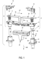
Figure 1 is a schematic and exploded representation in perspective of an example embodiment of a battery connection assembly; -
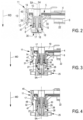
Figure 2 is a schematic cross-section of a power connector of the battery connection assembly shown inFigure 1 , this power connector being represented with the cap in delivery position; -
Figure 3 is a schematic cross-section of the power connector shown inFigure 2 , this power connector being inserted in the header cavity of a header connector, the power connector and the header connector being in an intermediate position in which the cap is still in the delivery position; -
Figure 4 is similar toFigure 3 , the cap being represented in the connection position; -
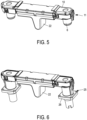
Figure 5 is a schematic representation in perspective of a busbar connection assembly for the battery connection assembly shown inFigure 1 ; -
Figure 6 is a schematic representation in perspective of the battery connection assembly shown inFigure 1 ; -
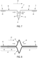
Figure 7 is a schematic side view of the busbar to be mounted in the battery connection assembly offigure 1 ; -
Figure 8 is a schematic side view of another example of busbar shape. - An example of an embodiment of a battery connection assembly is shown in
Figure 1 . According to this example, the battery connection assembly 1 comprises a busbar connection assembly 2 (see alsoFigure 5 ) which connects through arespective header connector 25, two poles, positive and negative respectively, of two battery modules (not shown). - The
busbar connection assembly 2 comprises twopower connectors 3, each one located at arespective busbar end 5 of abusbar 4. It will be noted that, although the present disclosure relates to abusbar connection assembly 2 comprising twopower connectors 3, the design of asingle power connector 3 for connecting a battery module to any power circuit, through a busbar, can be derivable from this description. It is sufficient to replace at least one of thepower connectors 3 with a suitable connector for connection to that circuit. - The
busbar 4 is for example made of plurality of conductive layers (e.g. of copper or a copper alloy). In other words, thebusbar 4 has a multi-layered structure (e.g. with 6 layers). The layers are maintained together only at eachbusbar end 5 by a kind of rivet 49 (seeFigure 7 ), to which aconnector terminal 7 is mechanically fastened and electrically connected. Thebusbar 4 extends essentially longitudinally along a longitudinal direction LD. More particularly, as shown inFigure 1 and7 , thebusbar 4 has twostraight portions 33 extending longitudinally along the longitudinal direction LD and in between of which is located a V-shaped portion 19. The V-shaped portion 19 comprises twobranches 20 linked at thevertex 21 of the V-shaped portion 19. The V-shaped portion 19 is configured so as to allow the two busbar ends 5 (i.e. the two straight portions 33) to be displaced relative to each other at least parallel to the longitudinal direction LD of the busbar 4 (see the arrows inFigure 7 ). For this purpose, the V-shaped portion 19 comprises twothrust portions 50 at right angle to thestraight portions 33, and the angle α between thesebranches 20 is equal or less than 30 degrees, for example. These features prevent thebusbar 4 from bending upwards when a compression force is applied which tends to bring theconnection terminals 7 towards each other. Each layer is 0,3mm thick. To achieve an appropriate flexibility, the total height of the V-shape is, for example, 40mm. - The V-
shaped portion 19 is housed in a cover 22 (seeFigures 1 ,5 and 6 ). Thecover 22 provides a protection to at least the IP2X level. Thecover 22 has a tooth shape (triangle shape) extending essentially in a mating direction MD, from abase 23 to anapex 24. Such a configuration provides the advantage that thecover 22 is located in a volume comprised between the two power connectors 3 (SeeFigures 5 and 6 ). In other words, this configuration is rather compact and does not add more height (i.e. in the mating direction MD) to thebusbar connection assembly 2. -
Figure 8 shows abusbar 40 with an alternative shape. Thebusbar 40 is for example made of plurality of conductive layers (e.g. of copper or a copper alloy). In other words, thebusbar 40 has a multi-layered structure. Contrarily, to the layers of the example illustrated inFigure 7 , in this embodiment, the layers are all the same. Indeed, as illustrated inFigure 9 , the layers are two adjacent layers are placed head to tail. This provides an economic advantage in terms of the manufacture of the layers. The layers are maintained together only at eachbusbar end 43 with a kind of rivet (not shown) to which a connector terminal 7 (not shown inFigure 8 ) is mechanically fastened and electrically connected. Alternatively, the layers are maintained together by theconnector terminal 7 itself. Thebusbar 40 extends essentially longitudinally along a longitudinal direction LD. However, as shown inFigure 8 , thebusbar 40 has twostraight portions 41 extending essentially longitudinally along the longitudinal direction LD and two opposite V-shapedportions 42. The two opposite V-shapedportions 42 are located between the twostraight portions 41. Each one of the twostraight portions 41 has afixation portion 44 and an intermediate portion 51. Eachfixation portion 44 serves to fix arespective connector terminal 7. The illustrated configuration is symmetrical and prevents prevent thebusbar 4 from bending upwards when a compression force is applied which tends to bring theconnection terminals 7 towards each other. - The
busbar 40 illustrated inFigure 8 has the advantage of having a good flexible behaviour when thebusbar 40 is compressed in the longitudinal direction LD. - As shown in particular in
Figure 2 , eachpower connector 3 comprises an electrically insulatingconnector housing 6, an electrically insulatingcap 10 and aconnector terminal 7. For example, theconnector housing 6 and the electrically insulatingcap 10 are made of moulded plastic. Eachconnector housing 6 accommodates aconnector terminal 7 electrically connected to arespective busbar end 5. - In the illustrated example, each
connector terminal 7 is a female terminal. Eachconnector terminal 7 comprises a crown orsleeve 35 fastened to abusbar end 5. A plurality ofcontact blades 15 extends longitudinally essentially in the mating direction MD and is arranged symmetrically around a circular symmetry axis SA which is parallel to the mating direction MD. Eachcontact blade 15 extends longitudinally from thecrown 35, with which it is integral, to afree end 16. - Each
connector housing 6 comprises a guidingportion 8 in which aconnection portion 9 of theconnector terminal 7 is housed. More particularly, eachfree end 16 of acontact blade 15 is located in the corresponding guidingportion 8. - Each
cap 10 at least partially closes theconnector housing 6. Eachcap 10 is configured so as to prevent theconnector terminal 7 and thebusbar end 5 housed in theconnector housing 6 from being touched by an operator (in other words, theconnector housing 6 and thecap 10 provide a protection to at least the IP2X level). - Each one of the
connector terminals 7 and busbar ends 5 are mechanically and rigidly attached into arespective cap 10. More precisely, eachcap 10 has afastening peg 34 that is forced into acrown 35 of a connector terminal 7 (however several other means can be envisioned for fastening thecap 10 onto aconnector terminal 7 and/or the busbar 4). Thecap 10, theconnector terminal 7 and thebusbar end 5 are movable together relative to theconnector housing 6 between at least a delivery position (Figures 2 and5 ) and a connection position (Figures 4 and6 ). - In the delivery position (
Figure 2 ), theconnection portion 9 is retracted further into the guidingportion 8 than in the connection position (Figure 4 ). In other words, in the delivery position, the free ends 16 of thecontact blades 15 are away from themating face 36 of the guiding portion 8 (thismating face 36 corresponds to the opening through which the terminal of a counter-connector can be inserted). - Each
cap 10 comprises cap locking means 11. The cap locking means 11 comprises alever 13 hinged on thecap 10. Thelever 13 comprises a lockingportion 39 and anactuating portion 45, respectively located on each side of a hinge. The lockingportion 39 comprises afirst stop 14 engaging aprotrusion 12 integral with theconnector housing 6, for holding thecap 10 and theconnector housing 6 in the delivery position. - The cap locking means 11 is actuatable between a locked position and an unlocked position. More particularly, the CPA locking means rotates/tilts about the hinge between the locked position and the unlocked position. In its locked position, the locking means 11 engages the
protrusion 12 to hold thecap 10 and theconnector housing 6 together in the delivery position. In its unlocked position, the locking means 11 releases thecap 10 from theprotrusion 12, so as to allow thecap 10 to be pushed into the connection position, by an operator (or a robot). - Each
cap 10 comprised afinger 17 extending essentially parallel to the mating direction MD, from thefastening peg 34 to atip 18. Thefinger 17 is integral with thecap 10. In the illustrated example, thefinger 17 has a cylindrical shape. Theconnection portion 9 of theconnector terminal 7 is retracted behind thetip 18. Thereby, thefinger 17 and the guidingportion 8 provides an IP2X protection. - As illustrated in
Figures 1 ,3 ,4 and6 , aheader connector 25 comprises aheader housing 26. Aheader terminal 27 is housed in eachheader housing 26. Eachheader housing 26 is made of an electrically insulating material (for example, it is made of moulded plastic). Eachheader housing 26 has aheader cavity 28 within which aconnection portion 29 of theheader terminal 27 protrudes. Theheader terminal 27 is configured so as to be mated with theconnector terminal 7. - In the illustrated example, the
header terminal 27 is a male terminal. Theheader terminal 27 has essentially a cylindrical shape with a cylindrical axis SA parallel to the mating direction MD. Theheader terminal 27 has arecess 37 extending longitudinally parallel to the mating direction MD. Theheader terminal 27 is made of conductive material such as copper or a copper alloy for example. Theheader terminal 27 comprises aninsulating end piece 30. The insulatingend piece 30 is partially inserted in therecess 37. The insulatingend piece 30 has aring 38 which covers the circular edge of the free end of theheader terminal 27, thereby theheader housing 26 and the insulatingend piece 30 provide an IP2X protection. The insulatingend piece 30 forms a hollow cylinder configured to receive at least a portion of thefinger 17. - In order to connect two electrical battery modules of electrical or hybrid vehicle, the following method is implemented by an operator (alternatively by a robot).
- During a pre-positioning step the two guiding
portions 8 of abusbar connection assembly 2 are each respectively aligned with aheader connector 25 of an electrical battery module and each guidingportion 8 is positioned opposite arespective header cavity 28. - During a plugging step, each guiding
portion 8 is inserted in arespective header cavity 28 up to an intermediate position in which the cap locking means 11 of eachpower connector 3 interacts with respective unlocking means 31 comprised on eachheader connector 25. In this intermediate position, the cap locking means 11 are still in the locked position (figure 3 ). At this stage, thefree end 16 of thecontact blades 15 rests on the insulating end piece 30 (i.e. there is no risk of electrical contact between theconnector terminals 7 and the header terminals 27). - During a connecting step, the
cap 10 is pushed in the mating direction MD so that the cap locking means 11 is released by the unlockingmeans 31 and can be moved up to a configuration wherein thecap 10 is in its connection position. For example, the unlockingmeans 31 comprises atooth 48 with an inclined surface and asecond stop 47 integral with thelever 13. While thecap 10 is pushed in the mating direction MD, thesecond stop 47 slides on the inclined surface (in other words the incline surface is part of the unlocking means 31). Thereby, thelever 13 is tilted and thefirst stop 14 is released from theprotrusion 12. When thecap 10 is further pushed in the mating MD, the cap locking means 11 locks onto header locking means 32 integral with theheader connector 25. More particularly, for example, thesecond stop 47 is blocked by a stop surface behind the tooth 48 (in other words the stop surface forms header locking means 32). In this configuration, the guidingportion 8 is inserted in theheader cavity 28 in a final position and thecap 10 is in its connection position. - In the illustrated example, the cap locking means 11 and the locking means used for locking the
power connector 3 and theheader connector 25 together in the final position, involves thesame lever 13. However, alternatively, these means can be distinct. - In order to un-mate the
power connector 3 and theheader connector 25, an operator pushes on the actuatingportion 45 of thelever 13, and pull thecap 10 in a direction opposite to the mating direction MD. - As one can understand, positioning the connector terminals 7 (i.e. busbar terminals) on the header terminals 27 (i.e battery terminals) and establishing an electrical contact between them are distinct operations. During the positioning (i.e. prepositioning and intermediate plugging steps), the
connection portion 9 of theconnector terminals 7 cannot electrically connect thecorresponding header terminal 27. Indeed, the cap 10 (onto which theconnector terminal 7 is mounted) is retained in the delivery position by the cap locking means 11. This is only when thepower connector 3 is well positioned onto theheader connector 25, that the cap locking means 11 can be released so as to allow thecap 10 to be pushed to its connection position in which theconnector terminal 7 connect theheader terminal 27.
Claims (12)
- A power connector (3) for connecting a busbar (4) to an electrical battery module, the power connector (3) comprising,an electrically conductive busbar (4) having a busbar end (5) ,an electrically insulating connector housing (6) accommodating a connector terminal (7) electrically connected to the busbar end (5), the connector housing (6) having a guiding portion (8) in which a connection portion (9) of the connector terminal (7) is housed,an electrically insulating cap (10) at least partially closing the connector housing (6) and preventing the connector terminal (7) and the busbar end (5) from being touched by an operator finger,characterized in that the connector terminal (7) and busbar end (5) are mechanically and rigidly attached into the cap (10), in that the cap (10), the connector terminal (7) and the busbar end (5) are movable together relative to the connector housing (6) between at least a delivery position and a connection position, in the delivery position the connection portion (9) being retracted further into the guiding portion (8) than in the connection position, and in that the cap (10) comprises cap locking means (11), the cap locking means (11) being actuatable between a locked position in which it holds the cap (10) and the connector housing (6) in the delivery position and an unlocked position wherein the cap (10) and the connector housing (6) are released so as to allow the cap (10) to be pushed into the connection position.
- The power connector (3) according to claim 1, wherein the connector housing (6) comprises a protrusion (12) and the cap locking means (11) comprises a lever (13) hinged on the cap (10), the lever (13) comprising a first stop (14) engaging the protrusion (12), for holding the cap (10) and the connector housing (6) in the delivery position.
- The power connector (3) according to claim 1 or 2, wherein the connector terminal (7) is a female terminal having contact blades (15) extending longitudinally essentially in the mating direction (MD) and arranged symmetrically around a symmetry axis (SA) which is parallel to the mating direction (MD), each contact blade (15) having a free end (16), each free end (16) being located inside the guiding portion (8), and wherein the cap (10) comprises a finger (17) extending essentially parallel to the symmetry axis (SA), the cap (10) and the finger (17) being integral, the finger (17) having a tip (18) positioned within the guiding portion (8) and further in the mating direction (MD) than each free end (16) of contact blade (15).
- A busbar connection assembly (2) comprising a power connector (3) according to any one of claims 1 to 3, comprising one busbar (4), two connector housings (6) and two caps (10), wherein the busbar (4) extends in a longitudinal direction (LD) between two busbar ends (5), each busbar end (5) being mechanically and electrically connected to a connector terminal (7) housed in the guiding portion (8) of one of the two connector housings (6).
- The busbar connection assembly (2) according to claim 4, wherein the busbar (4) is made of a plurality of conductive layers.
- The busbar connection assembly (2) according to claim 4 or 5, wherein the busbar (4) has a V-shaped portion (19) allowing the two busbar ends (5) to be displaced relative to each other at least in the longitudinal direction (LD) of the busbar (4).
- The busbar connection assembly (2) according to claim 6, wherein the V-shaped portion (19) comprises two branches (20) linked at the vertex (21) of the V-shaped portion (19), the angle (α) between these branches (20) being equal or less than 30 degrees.
- The busbar connection assembly (2) according to claim 6 or 7, wherein the V-shaped portion (19) is housed in a cover (22), the cover (22) forming a tooth extending from a base (23) to an apex (24), essentially in the mating direction (MD).
- A battery connection assembly (1) comprising the power connector (3) of any of claims 1 to 3, a header connector (25), the power connector (3) being configured to mate the header connector (25) in a mating direction (MD), the header connector (25) being mounted on an electrical battery module and comprising a header housing (26) in which a header terminal (27) is housed, the header housing (26) having a header cavity (28) within which a connection portion (29) of the header terminal (27) protrudes, the header terminal (27) being configured so as to be mated with the connector terminal (7),
wherein the guiding portion (8) is configured so as to be inserted in the header cavity (28) in a final position, and the cap locking means (11) is configured to be unlocked by the header connector (25) when the guiding portion (8) is inserted in the header cavity (28) towards the final position, so as to release the connector housing (6) and the connector cap (10) from the delivery position and so as to allow the cap (10) to be pushed in the mating direction (MD) up to the connection position. - The battery connection assembly (1) according to claim 9, wherein the cap (10) comprises a finger (17) extending essentially parallel to the mating direction (MD) and the header terminal has a recess extending longitudinally parallel to the mating direction (MD) and configured to receive at least a portion of the finger (17).
- The battery connection assembly (1) according to claim 9 or 10, wherein the header terminal (27) is a male terminal and the connector terminal (7) is a female terminal, wherein the header terminal (27) comprises an insulating end piece (30) and the connector terminal (7) comprises contact blades (15) extending longitudinally essentially in the mating direction (MD) and symmetrically arranged around a symmetry axis (SA) which is parallel to the mating direction (MD), each contact blade (15) having a free end (16), and wherein at least one free end (16) of contact blade (15) rests on the insulating end piece (30) in a configuration in which the power connector (3) and the header connector (25) are in an intermediate position in which the guiding portion (8) is inserted in the header cavity (28) and the cap locking means (11) are still in the locked position.
- A method of connecting two electrical battery modules of electrical or hybrid vehicle, the method comprising- a pre-positioning step comprising the provision of two electrical battery modules and a busbar connection assembly (2) according to any one of claims 4 to 8, each electrical battery module having at least one header connector (25) comprising a header housing (26) in which a header terminal (27) is housed, each header housing (26) having a header cavity (28) within which a connection portion (9) of a respective header terminal (27) protrudes, and comprising positioning each guiding portion (8) opposite a respective header cavity (28),- a plugging step comprising inserting each guiding portion (8) in a respective header cavity (28), so that the cap locking means (11) of each power connector (3) interacts with respective unlocking means (31) comprised on a header connector (25),- a connecting step comprising pushing on the cap (10) in the mating direction (MD) so that the cap locking means (11) is displaced beyond the unlocking means (31) and so that the cap locking means (11) locks onto header locking means (32) comprised on a header connector (25).
Priority Applications (1)
| Application Number | Priority Date | Filing Date | Title |
|---|---|---|---|
| EP22211761.6A EP4383440B1 (en) | 2022-12-06 | 2022-12-06 | Power connector for connecting a busbar to an electrical battery module and battery connection assembly |
Applications Claiming Priority (1)
| Application Number | Priority Date | Filing Date | Title |
|---|---|---|---|
| EP22211761.6A EP4383440B1 (en) | 2022-12-06 | 2022-12-06 | Power connector for connecting a busbar to an electrical battery module and battery connection assembly |
Publications (2)
| Publication Number | Publication Date |
|---|---|
| EP4383440A1 true EP4383440A1 (en) | 2024-06-12 |
| EP4383440B1 EP4383440B1 (en) | 2026-02-25 |
Family
ID=84421645
Family Applications (1)
| Application Number | Title | Priority Date | Filing Date |
|---|---|---|---|
| EP22211761.6A Active EP4383440B1 (en) | 2022-12-06 | 2022-12-06 | Power connector for connecting a busbar to an electrical battery module and battery connection assembly |
Country Status (1)
| Country | Link |
|---|---|
| EP (1) | EP4383440B1 (en) |
Citations (3)
| Publication number | Priority date | Publication date | Assignee | Title |
|---|---|---|---|---|
| WO2013178433A1 (en) * | 2012-05-30 | 2013-12-05 | Delphi International Operations Luxembourg S.À R.L. | Interconnection assembly for vehicle devices and method of interconnection |
| US8628335B1 (en) * | 2012-12-07 | 2014-01-14 | Tyco Electronics Corporation | Power terminal connector |
| US20150171401A1 (en) * | 2012-07-05 | 2015-06-18 | Sk Innovation Co., Ltd. | Battery Pack |
-
2022
- 2022-12-06 EP EP22211761.6A patent/EP4383440B1/en active Active
Patent Citations (3)
| Publication number | Priority date | Publication date | Assignee | Title |
|---|---|---|---|---|
| WO2013178433A1 (en) * | 2012-05-30 | 2013-12-05 | Delphi International Operations Luxembourg S.À R.L. | Interconnection assembly for vehicle devices and method of interconnection |
| US20150171401A1 (en) * | 2012-07-05 | 2015-06-18 | Sk Innovation Co., Ltd. | Battery Pack |
| US8628335B1 (en) * | 2012-12-07 | 2014-01-14 | Tyco Electronics Corporation | Power terminal connector |
Also Published As
| Publication number | Publication date |
|---|---|
| EP4383440B1 (en) | 2026-02-25 |
Similar Documents
| Publication | Publication Date | Title |
|---|---|---|
| EP4101685B1 (en) | Adapter system for electrical connection of a connector of a cabling to different contact arrangements of different charging sockets | |
| US10141669B2 (en) | Plug connector having a tab terminal for a power connector system | |
| US10128624B2 (en) | Power connector system | |
| US11303073B2 (en) | Charging inlet assembly | |
| EP3284142B1 (en) | Quick connect power connector system | |
| CN103038948B (en) | Electrical connection busbar | |
| US6004158A (en) | Electrical connector with secondary locking plates | |
| US6629863B2 (en) | Vehicle battery plug-in connection arrangement | |
| US6964579B2 (en) | Position assured connector | |
| EP0384592B1 (en) | Quick disconnect automotive battery connection | |
| EP2624376B1 (en) | Cell voltage detecting connector | |
| CN113424370A (en) | Replaceable pin for terminal of charging port assembly | |
| US7608360B2 (en) | Rechargeable battery and method for its production | |
| EP4383440B1 (en) | Power connector for connecting a busbar to an electrical battery module and battery connection assembly | |
| WO2013178433A1 (en) | Interconnection assembly for vehicle devices and method of interconnection | |
| US12494608B2 (en) | Power harness using busbar | |
| US12479318B2 (en) | Charging inlet assembly having a power harness | |
| EP4383471A1 (en) | Power connector with a movable touch-proof element | |
| US12580328B2 (en) | Power connector system with lever for tightening a connecting bolt | |
| US20240322382A1 (en) | Battery connector system | |
| JP7787246B2 (en) | Plug connectors, plug connector mating parts, and plug connector systems | |
| US12482986B2 (en) | Integrally molded power connector housing having an insert held by a breakable bridge | |
| AU2025201536A1 (en) | Electrical connector | |
| CN116260010A (en) | Wire harness connector and manufacturing method thereof |
Legal Events
| Date | Code | Title | Description |
|---|---|---|---|
| PUAI | Public reference made under article 153(3) epc to a published international application that has entered the european phase |
Free format text: ORIGINAL CODE: 0009012 |
|
| STAA | Information on the status of an ep patent application or granted ep patent |
Free format text: STATUS: THE APPLICATION HAS BEEN PUBLISHED |
|
| AK | Designated contracting states |
Kind code of ref document: A1 Designated state(s): AL AT BE BG CH CY CZ DE DK EE ES FI FR GB GR HR HU IE IS IT LI LT LU LV MC ME MK MT NL NO PL PT RO RS SE SI SK SM TR |
|
| RAP1 | Party data changed (applicant data changed or rights of an application transferred) |
Owner name: APTIV TECHNOLOGIES AG |
|
| STAA | Information on the status of an ep patent application or granted ep patent |
Free format text: STATUS: REQUEST FOR EXAMINATION WAS MADE |
|
| 17P | Request for examination filed |
Effective date: 20241202 |
|
| RBV | Designated contracting states (corrected) |
Designated state(s): AL AT BE BG CH CY CZ DE DK EE ES FI FR GB GR HR HU IE IS IT LI LT LU LV MC ME MK MT NL NO PL PT RO RS SE SI SK SM TR |
|
| STAA | Information on the status of an ep patent application or granted ep patent |
Free format text: STATUS: EXAMINATION IS IN PROGRESS |
|
| 17Q | First examination report despatched |
Effective date: 20250122 |
|
| GRAP | Despatch of communication of intention to grant a patent |
Free format text: ORIGINAL CODE: EPIDOSNIGR1 |
|
| STAA | Information on the status of an ep patent application or granted ep patent |
Free format text: STATUS: GRANT OF PATENT IS INTENDED |
|
| INTG | Intention to grant announced |
Effective date: 20251211 |
|
| GRAS | Grant fee paid |
Free format text: ORIGINAL CODE: EPIDOSNIGR3 |
|
| GRAA | (expected) grant |
Free format text: ORIGINAL CODE: 0009210 |
|
| STAA | Information on the status of an ep patent application or granted ep patent |
Free format text: STATUS: THE PATENT HAS BEEN GRANTED |
|
| AK | Designated contracting states |
Kind code of ref document: B1 Designated state(s): AL AT BE BG CH CY CZ DE DK EE ES FI FR GB GR HR HU IE IS IT LI LT LU LV MC ME MK MT NL NO PL PT RO RS SE SI SK SM TR |
|
| RAP3 | Party data changed (applicant data changed or rights of an application transferred) |
Owner name: APTIV TECHNOLOGIES AG |
|
| REG | Reference to a national code |
Ref country code: CH Ref legal event code: F10 Free format text: ST27 STATUS EVENT CODE: U-0-0-F10-F00 (AS PROVIDED BY THE NATIONAL OFFICE) Effective date: 20260225 Ref country code: GB Ref legal event code: FG4D |
|
| REG | Reference to a national code |
Ref country code: DE Ref legal event code: R096 Ref document number: 602022031060 Country of ref document: DE |
|
| REG | Reference to a national code |
Ref country code: IE Ref legal event code: FG4D |