EP4383431A1 - Pressure relief apparatus, cell, battery and electrical device - Google Patents
Pressure relief apparatus, cell, battery and electrical device Download PDFInfo
- Publication number
- EP4383431A1 EP4383431A1 EP22922692.3A EP22922692A EP4383431A1 EP 4383431 A1 EP4383431 A1 EP 4383431A1 EP 22922692 A EP22922692 A EP 22922692A EP 4383431 A1 EP4383431 A1 EP 4383431A1
- Authority
- EP
- European Patent Office
- Prior art keywords
- pressure relief
- groove
- pressure
- battery cell
- weak portion
- Prior art date
- Legal status (The legal status is an assumption and is not a legal conclusion. Google has not performed a legal analysis and makes no representation as to the accuracy of the status listed.)
- Granted
Links
Images


Classifications
-
- H—ELECTRICITY
- H01—ELECTRIC ELEMENTS
- H01M—PROCESSES OR MEANS, e.g. BATTERIES, FOR THE DIRECT CONVERSION OF CHEMICAL ENERGY INTO ELECTRICAL ENERGY
- H01M50/00—Constructional details or processes of manufacture of the non-active parts of electrochemical cells other than fuel cells, e.g. hybrid cells
- H01M50/10—Primary casings; Jackets or wrappings
- H01M50/102—Primary casings; Jackets or wrappings characterised by their shape or physical structure
- H01M50/107—Primary casings; Jackets or wrappings characterised by their shape or physical structure having curved cross-section, e.g. round or elliptic
-
- H—ELECTRICITY
- H01—ELECTRIC ELEMENTS
- H01M—PROCESSES OR MEANS, e.g. BATTERIES, FOR THE DIRECT CONVERSION OF CHEMICAL ENERGY INTO ELECTRICAL ENERGY
- H01M50/00—Constructional details or processes of manufacture of the non-active parts of electrochemical cells other than fuel cells, e.g. hybrid cells
- H01M50/30—Arrangements for facilitating escape of gases
- H01M50/342—Non-re-sealable arrangements
- H01M50/3425—Non-re-sealable arrangements in the form of rupturable membranes or weakened parts, e.g. pierced with the aid of a sharp member
-
- F—MECHANICAL ENGINEERING; LIGHTING; HEATING; WEAPONS; BLASTING
- F16—ENGINEERING ELEMENTS AND UNITS; GENERAL MEASURES FOR PRODUCING AND MAINTAINING EFFECTIVE FUNCTIONING OF MACHINES OR INSTALLATIONS; THERMAL INSULATION IN GENERAL
- F16K—VALVES; TAPS; COCKS; ACTUATING-FLOATS; DEVICES FOR VENTING OR AERATING
- F16K17/00—Safety valves; Equalising valves, e.g. pressure relief valves
- F16K17/02—Safety valves; Equalising valves, e.g. pressure relief valves opening on surplus pressure on one side; closing on insufficient pressure on one side
- F16K17/14—Safety valves; Equalising valves, e.g. pressure relief valves opening on surplus pressure on one side; closing on insufficient pressure on one side with fracturing member
- F16K17/16—Safety valves; Equalising valves, e.g. pressure relief valves opening on surplus pressure on one side; closing on insufficient pressure on one side with fracturing member with fracturing diaphragm ; Rupture discs
-
- H—ELECTRICITY
- H01—ELECTRIC ELEMENTS
- H01M—PROCESSES OR MEANS, e.g. BATTERIES, FOR THE DIRECT CONVERSION OF CHEMICAL ENERGY INTO ELECTRICAL ENERGY
- H01M50/00—Constructional details or processes of manufacture of the non-active parts of electrochemical cells other than fuel cells, e.g. hybrid cells
- H01M50/10—Primary casings; Jackets or wrappings
- H01M50/147—Lids or covers
- H01M50/148—Lids or covers characterised by their shape
- H01M50/152—Lids or covers characterised by their shape for cells having curved cross-section, e.g. round or elliptic
-
- H—ELECTRICITY
- H01—ELECTRIC ELEMENTS
- H01M—PROCESSES OR MEANS, e.g. BATTERIES, FOR THE DIRECT CONVERSION OF CHEMICAL ENERGY INTO ELECTRICAL ENERGY
- H01M50/00—Constructional details or processes of manufacture of the non-active parts of electrochemical cells other than fuel cells, e.g. hybrid cells
- H01M50/30—Arrangements for facilitating escape of gases
-
- Y—GENERAL TAGGING OF NEW TECHNOLOGICAL DEVELOPMENTS; GENERAL TAGGING OF CROSS-SECTIONAL TECHNOLOGIES SPANNING OVER SEVERAL SECTIONS OF THE IPC; TECHNICAL SUBJECTS COVERED BY FORMER USPC CROSS-REFERENCE ART COLLECTIONS [XRACs] AND DIGESTS
- Y02—TECHNOLOGIES OR APPLICATIONS FOR MITIGATION OR ADAPTATION AGAINST CLIMATE CHANGE
- Y02E—REDUCTION OF GREENHOUSE GAS [GHG] EMISSIONS, RELATED TO ENERGY GENERATION, TRANSMISSION OR DISTRIBUTION
- Y02E60/00—Enabling technologies; Technologies with a potential or indirect contribution to GHG emissions mitigation
- Y02E60/10—Energy storage using batteries
Definitions
- the present application relates to the field of battery technology, and particularly to a pressure relief apparatus, a battery cell, a battery, and a power consumption device.
- batteries are increasingly widely used, for example, in mobile phones, notebook computers, scooters, electric vehicles, electric airplanes, electric ships, electric toy cars, electric toy boats, electric toy planes, and electric tools.
- Embodiments of the present application provide a pressure relief apparatus, a battery cell, a battery, and a power consumption device, where the safety of the battery cell can be effectively improved.
- an embodiment of the present application provides a pressure relief apparatus, applied in a battery cell, and including: a pressure relief body having a first surface and a second surface oppositely disposed in a thickness direction thereof; and two pressure relief grooves oppositely disposed in the thickness direction and disposed on the first surface and the second surface separately, where a weak portion is formed between the two pressure relief grooves, and the weak portion is configured to rupture when a pressure or a temperature inside the battery cell reaches a threshold, so as to release the pressure inside the battery cell.
- the pressure relief grooves are disposed on both the first surface and the second surface of the pressure relief body to obtain a relatively low residual thickness and reduce a thickness of the weak portion, so that the weak portion is prone to rupture to reduce a detonation pressure of the pressure relief apparatus, and the pressure relief body can release pressure in a timely manner to reduce risks of fire, explosion, and the like in the battery cell and effectively improve the safety of the battery cell.
- a distance between the first surface and the second surface is a first distance
- a ratio of a minimum thickness of the weak portion to the first distance is 0.12-0.5. If the ratio of the minimum thickness of the weak portion to the first distance is too small, the minimum thickness of the weak portion is smaller, and the weak portion will rupture in a forming process. Even if the weak portion does not rupture, because the strength of the pressure relief body is low, the weak portion is prone to rupture to release pressure in a vibration environment or in a case that the pressure or the temperature inside the battery cell is far from the threshold, which affects the service life of the battery cell.
- the ratio of the minimum thickness of the weak portion to the first distance is set to 0.12-0.5, which not only ensures that the pressure relief apparatus can release pressure in a timely manner when the pressure inside the battery cell reaches the threshold, but can also ensure that the pressure relief apparatus has sufficient strength before pressure relief.
- the pressure relief groove extends in a circumferential direction of the pressure relief body and confines a pressure relief portion; and the pressure relief portion is configured to open with the weak portion as a boundary when the pressure or temperature inside the battery cell reaches the threshold, so as to release the pressure inside the battery cell.
- the pressure relief groove is in an arc shape extending in the circumferential direction of the pressure relief body.
- the shape of the pressure relief groove with this structure is regular, so that the pressure relief portion is easy to machine and can open regularly during pressure relief.
- the pressure relief body further has an outer surface and an inner surface, the outer surface is oppositely disposed to the inner surface in the thickness direction, and the pressure relief portion is configured to open from the inner surface towards the outer surface when the pressure or the temperature inside the battery cell reaches the threshold; and the pressure relief body is provided with a concave portion, the concave portion is recessed, in the thickness direction, from the outer surface in a direction towards the inner surface, and a bottom surface of the concave portion forms the first surface.
- the concave portion can provide a space for avoidance when the pressure relief portion opens outwards, and even if there is an obstacle on the outer surface of the pressure relief body, the pressure relief portion can open normally, thereby reducing a risk of being unable to open the pressure relief portion due to abutment of the obstacle against the outer surface.
- a convex portion protruding from the inner surface is formed at a position, corresponding to the concave portion, of the pressure relief body, and a face, away from the inner surface, of the convex portion forms the second surface in the thickness direction.
- the convex portion can improve the strength of the area where the concave portion is disposed in the pressure relief body, and avoid a problem of low partial strength caused by the concave portion in the pressure relief body.
- the pressure relief groove includes: two groove side surfaces facing each other along a width direction of the pressure relief groove; and a groove bottom surface connected to the two groove side surfaces, where the weak portion is formed in an area between the groove bottom surfaces of the two pressure relief grooves.
- the pressure relief groove of this structure is easy to machine and form, and the pressure relief groove may be formed by stamping.
- the groove bottom surface is an arc surface recessed in a depth direction of the pressure relief groove.
- the weak portion is of a structure with gradually decreasing thickness from two sides to a middle position, the weak portion can rupture more easily from the weakest position in the middle during pressure relief, and the pressure relief apparatus can rupture to release pressure in a timely manner when the pressure or temperature inside the battery cell reaches the threshold.
- the groove bottom surface comprises a bottom plane and arc chamfer surfaces
- the bottom plane is connected to each of the groove side surfaces through one of the arc chamfer surfaces.
- a distance between the two groove side surfaces gradually decreases in the depth direction of the pressure relief groove. This structure can effectively reduce the width of the weak portion, so that the weak portion is prone to rupture when the pressure or temperature inside the battery cell reaches the threshold.
- an anti-oxidation layer is formed on the surface of the pressure relief body, and the anti-oxidation layer extends along a wall surface of the pressure relief groove in an area where the pressure relief groove is disposed.
- the anti-oxidation layer protects the pressure relief body to avoid oxidation of the pressure relief body.
- the anti-oxidation layer can also protect the area where the pressure relief groove is disposed in the pressure relief body, thereby reducing the risk of reduced strength of the weak portion due to oxidation of the pressure relief body in the area where the pressure relief groove is disposed.
- a thickness of the anti-oxidation layer in the area of the pressure relief groove is smaller than that of the anti-oxidation layer in remaining areas. This reduces an impact of the anti-oxidation layer in the area of the pressure relief groove on the weak portion and ensures that the weak portion can rupture to release pressure in a timely manner when the pressure or temperature inside the battery cell reaches the threshold.
- an embodiment of the present application provides a battery cell, including; an electrode assembly; and a shell, configured for accommodating the electrode assembly, where the shell includes the pressure relief apparatus provided in any of the foregoing embodiments of the first aspect.
- the shell further includes a shell body, the shell body is configured for accommodating the electrode assembly, the shell body has an opening, and the pressure relief body is configured for covering the opening.
- an embodiment of the present application provides a battery, including: the battery cell provided in any of the foregoing embodiments of the second aspect; and a box body configured for accommodating the battery cell.
- an embodiment of the present application provides a power consumption device, including the battery provided in any of the foregoing embodiments of the third aspect.
- an embodiment of the present application provides a manufacturing method for a pressure relief apparatus, including: providing a pressure relief body, where the pressure relief body has a first surface and a second surface oppositely disposed in a thickness direction thereof; and machining a pressure relief groove on each of the first surface and the second surface, so that the pressure relief groove on the first surface and the pressure relief groove on the second surface are oppositely disposed in the thickness direction of the pressure relief apparatus, a weak portion is formed between the pressure relief groove on the first surface and the pressure relief groove on the second surface, and the weak portion is configured to rupture when a pressure or a temperature inside a battery cell reaches a threshold, so as to release the pressure inside the battery cell.
- an embodiment of the present application further provides a manufacturing device for a pressure relief apparatus, including: a provision apparatus, configured to provide a pressure relief body, where the pressure relief body has a first surface and a second surface oppositely disposed in a thickness direction thereof; and a machining apparatus, configured to machine a pressure relief groove on each of the first surface and the second surface, so that the pressure relief groove on the first surface and the pressure relief groove on the second surface are oppositely disposed in the thickness direction of the pressure relief apparatus, a weak portion is formed between the pressure relief groove on the first surface and the pressure relief groove on the second surface, and the weak portion is configured to rupture when a pressure or a temperature inside a battery cell reaches a threshold, so as to release the pressure inside the battery cell.
- connection may be a fixed connection, a detachable connection, an integral connection, a direct connection, or an indirect connection through a medium, or an internal communication of two elements.
- a and/or B may represent the following three cases: Only A exists, both A and B exist, and only B exists.
- the character "/" in the present application generally indicates an "or" relationship between successive associated objects.
- a plurality of means two (inclusive) or more.
- battery cells may include lithium-ion secondary batteries, lithium-ion primary batteries, lithium-sulfur batteries, sodium lithium-ion batteries, sodium-ion batteries, magnesium-ion batteries, or the like, which are not limited by the embodiments of the present application.
- the battery cells may also be cylindrical, flat, cuboid, or in other shapes, which are not limited by the embodiments of the present application.
- the battery cells are generally divided into three types according to the way of packaging: cylindrical battery cells, square battery cells, and soft package battery cells, which are not limited in the embodiments of the present application.
- the battery mentioned in the embodiments of the present application refers to a single physical module that includes one or more battery cells to provide a higher voltage and capacity.
- the battery mentioned in the present application may include a battery module or a battery pack.
- the battery generally includes a box body for packaging one or more battery cells. The box body may prevent liquid or other foreign matters from affecting the charging or discharging of the battery cells.
- the battery cell includes an electrode assembly and an electrolyte, and the electrode assembly is composed of a positive electrode sheet, a negative electrode sheet and a separator.
- the operation of the battery cell mainly relies on the movement of metal ions between the positive electrode sheet and the negative electrode sheet.
- the positive electrode sheet includes a positive electrode current collector and a positive electrode active material layer.
- the positive electrode active material layer is coated on a surface of the positive electrode current collector, and the positive electrode current collector not coated with the positive electrode active material layer protrudes from the positive electrode current collector coated with the positive electrode active material layer and is used as a positive tab.
- a material of the positive electrode current collector may be aluminum, and a positive electrode active material may be lithium cobalt oxide, lithium iron phosphate, ternary lithium, lithium manganate oxide, or the like.
- the negative electrode sheet includes a negative electrode current collector and a negative electrode active material layer.
- the negative electrode active material layer is coated on a surface of the negative electrode current collector, and the negative electrode current collector not coated with the negative electrode active material layer protrudes from the negative electrode current collector coated with the negative electrode active material layer and is used as a negative tab.
- a material of the negative electrode current collector may be copper, and a negative electrode active material may be carbon, silicon, or the like.
- a material of the separator may be polypropylene (PP), polyethylene (PE), or the like.
- the electrode assembly may be of a winding structure or a laminated structure, and the embodiments of the present application are not limited thereto.
- a pressure relief apparatus is generally disposed inside the battery cell. When a pressure or temperature inside the battery cell reaches a threshold, the pressure inside the battery cell is released through the pressure relief apparatus to ensure the safety of the battery cell.
- a pressure relief groove is generally disposed on a pressure relief body of the pressure relief apparatus, and during pressure relief, the pressure relief body ruptures from a position where the pressure relief groove is disposed to achieve a purpose of pressure relief.
- the embodiments of the present application provide a pressure relief apparatus, where a pressure relief groove is disposed on both a first surface and a second surface of a pressure relief body that are opposite, a weak portion is formed between the pressure relief groove on the first surface and the pressure relief groove on the second surface, and the weak portion is configured to rupture when a pressure or temperature inside a battery cell reaches a threshold to release the pressure inside the battery cell.
- the pressure relief groove is disposed on both the first surface and the second surface of the pressure relief body to obtain a relatively low residual thickness and reduce a thickness of the weak portion, so that the weak portion is prone to rupture to reduce a detonation pressure of the pressure relief apparatus, and the pressure relief body can release pressure in a timely manner to reduce risks of fire, explosion, and the like in the battery cell and effectively improve the safety of the battery cell.
- the pressure relief groove is disposed on both the first surface and the second surface of the pressure relief body, difficulties in forming can be effectively reduced, machining accuracy can be ensured, the thickness of the weak portion can be accurately controlled, and the thickness of the weak portion meets the detonation requirements.
- the pressure relief apparatus described in the embodiments of the present application is applicable to battery cells, batteries, and power consumption devices using batteries.
- the power consumption devices may be vehicles, mobile phones, portable devices, notebook computers, ships, spacecrafts, electric toys, electric tools, and the like.
- the vehicles may be oil-fueled vehicles, gas-fueled vehicles, or new energy vehicles, and the new energy vehicles may be pure electric vehicles, hybrid electric vehicles, extended range vehicles, or the like;
- the spacecrafts include airplanes, rockets, space shuttles, spaceships, and the like;
- the electric toys include fixed or mobile electric toys, such as game consoles, electric car toys, electric boat toys, and electric plane toys;
- the electric tools include electric metal cutting tools, electric grinding tools, electric assembly tools, and railway electric tools, such as electric drills, electric grinders, electric wrenches, electric screwdrivers, electric hammers, electric impact drills, concrete vibrators, and electric planers.
- the embodiments of the present application do not impose special limitations on the foregoing power consumption devices.
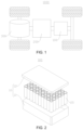
- FIG. 1 is a structural schematic diagram of a vehicle 1000 according to some embodiments of the present application.
- a battery 100 is disposed inside the vehicle 1000, and the battery 100 may be disposed at a bottom, head, or tail of the vehicle 1000.
- the battery 100 may be used for supplying power to the vehicle 1000.
- the battery 100 may be used as an operation power supply of the vehicle 1000.
- the vehicle 1000 may further include a controller 200 and a motor 300.
- the controller 200 is used for controlling the battery 100 to supply power to the motor 300, for example, for the working power demand of the vehicle 1000 during startup, navigation and running.
- the battery 100 may be used not only as an operation power supply of the vehicle 1000, but also as a driving power supply of the vehicle 1000 to replace or partially replace fuel or natural gas to provide driving power for the vehicle 1000.
- FIG. 2 is an exploded view of a battery 100 according to some embodiments of the present application.
- the battery 100 includes a box body 10 and battery cells 20, where the box body 10 is used for accommodating the battery cells 20.
- the box body 10 is a component that accommodates the battery cells 20, the box body 10 provides a space for the battery cells 20, and the box body 10 may have various structures.
- the box body 10 may include a first portion 11 and a second portion 12, and the first portion 11 and the second portion 12 cover each other to confine the space for accommodating the battery cells 20.
- the first portion 11 and the second portion 12 may be in various shapes, such as cuboid or cylindrical.
- the first portion 11 may be of a hollow structure with an open side
- the second portion 12 may also be of a hollow structure with an open side
- the open side of the second portion 12 covers the open side of the first portion 11 to form the box body 10 with the accommodating space.
- the first portion 11 is of a hollow structure with an open side
- the second portion 12 is of a plate-like structure
- the second portion 12 covers the open side of the first portion 11 to form the box body 10 with the accommodating space.
- the first portion 11 and the second portion 12 may be sealed through a sealing element, which may be a sealing ring, a sealant, or the like.
- the plurality of battery cells 20 may be connected in series, parallel, or series-parallel.
- the series-parallel connection refers to both series and parallel connection in the plurality of battery cells 20.
- the plurality of battery cells 20 may be first connected in series, parallel, or series-parallel to form a battery module, and then a plurality of battery modules may be connected in series, parallel, or series-parallel to form a whole accommodated in the box body 10.
- all the battery cells 20 may be directly connected in series, parallel, or series-parallel together, and then the whole formed by all the battery cells 20 is accommodated in the box body 10.
- the battery 100 may further include a converging component, and the plurality of battery cells 20 may be electrically connected through the converging component to implement the series, parallel, or series-parallel connection of the plurality of battery cells 20.
- the converging component may be a metal conductor, such as copper, iron, aluminum, stainless steel, or aluminum alloy.
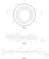
- FIG. 3 is an exploded view of a battery cell 20 according to some embodiments of the present application.
- the battery cell 20 may include a shell and an electrode assembly 21, where the shell is used for accommodating the electrode assembly 21.
- the shell may include a shell body 22, an end cover 23, and a pressure relief apparatus 24.
- the shell body 22 is a component used for accommodating the electrode assembly 21, and the shell body 22 may be of a hollow structure with an opening formed at one end, or the shell body 22 may be of a hollow structure with openings formed at two opposite ends.
- the shell body 22 may be in various shapes, such as cylindrical or cuboid.
- a material of the shell body 22 may be various, such as copper, iron, aluminum, steel, or aluminum alloy.
- the electrode assembly 21 is a component that undergoes electrochemical reactions in the battery cell 20.
- the electrode assembly 21 may include a positive electrode sheet, a negative electrode sheet, and a separator.
- the electrode assembly 21 may be of a winding structure formed by winding the positive electrode sheet, the separator, and the negative electrode sheet, or a stacked structure formed by stacking the positive electrode sheet, the separator, and the negative electrode sheet.
- the electrode assembly 21 has a positive tab and a negative tab, the positive tab may be a portion not coated with the positive electrode active material layer on the positive electrode sheet, and the negative tab may be a portion not coated with the negative electrode active material layer on the negative electrode sheet.
- the end cover 23 is a component that is configured to close to the opening of the shell body 22 to isolate an internal environment of the battery cell 20 from an external environment.
- the end cover 23 is closed to the opening of the shell body 22, and the end cover 23 and the shell body 22 jointly confine a sealed space for accommodating the electrode assembly 21, an electrolyte, and other components.
- a shape of the end cover 23 may be adapted to that of the shell body 22.
- the shell body 22 is of a cuboid structure, and the end cover 23 is of a rectangular plate structure matching the shell body 22.
- the shell body 22 is of a cylindrical structure, and the end cover 23 is of a circular plate structure matching the shell body 22.
- the end cover 23 may be made of various materials, such as copper, iron, aluminum, steel, or aluminum alloy.
- the shell body 22 is of a hollow structure with an opening formed at one end, one end cover 23 is correspondingly disposed. If the shell body 22 is of a hollow structure with openings formed at two ends, two end covers 23 are correspondingly disposed, and the two end covers 23 are closed to the two openings of the shell body 22 separately.
- An electrode terminal 25 may be disposed in the battery cell, the electrode terminal 25 may be disposed on the end cover 23 or the shell body 22, and the electrode terminal 25 is used for electrical connection with the electrode assembly 21 to output electrical energy of the battery cell 20.
- the electrode terminal 25 may be disposed on the two end covers 23, the electrode terminal 25 on one end cover 23 is electrically connected to the positive tab of the electrode assembly 21, and the electrode terminal 25 on the other end cover 23 is electrically connected to the negative tab of the electrode assembly 21. As shown in FIG.
- the electrode terminal 25 may be disposed on only the shell, the electrode terminal 25 may be electrically connected to the positive tab of the electrode assembly 21, and the end cover 23 is electrically connected to the negative tab of the electrode assembly 21.
- a current collecting member 26 may be further disposed in the battery cell 20 to achieve the electrical connection between the electrode terminal 25 and the tab or the end cover 23 and the tab.
- the electrode terminal 25 on the shell body 22 is connected to the positive tab of the electrode assembly 21 by means of a current collecting member 26, and the end cover 23 is connected to the negative tab of the electrode assembly 21 by means of another current collecting member 26.
- the pressure relief apparatus 24 is a component that releases the pressure inside the battery cell 20. When the pressure or temperature inside the battery cell 20 reaches a threshold, the pressure inside the battery cell 20 is released through the pressure relief apparatus 24. A specific structure of the pressure relief apparatus 24 will be explained in detail below with reference to the accompanying drawings.
- FIG. 4 is a structural schematic diagram of the pressure relief apparatus 24 shown in FIG. 3
- FIG. 5 is a partial view of the pressure relief apparatus 24 shown in FIG. 4
- An embodiment of the present application provides a pressure relief apparatus 24 used for a battery cell 20.
- the pressure relief apparatus 24 includes a pressure relief body 241 and two pressure relief grooves 242.
- the pressure relief body 241 has a first surface 2411 and a second surface 2412 oppositely disposed in its thickness direction Z.
- the two pressure relief grooves 242 are oppositely disposed in the thickness direction Z of the pressure relief apparatus 24 and disposed on the first surface 2411 and the second surface 2412 separately.
- a weak portion 2413 is formed between the two pressure relief grooves 242, and the weak portion 2413 is configured to rupture when the pressure or temperature inside the battery cell 20 reaches a threshold to release the pressure inside the battery cell 20.
- the pressure relief body 241 may be either at the end cover 23 or the shell body 22.
- the pressure relief body 241 may be an independent component mounted on the end cover 23, or an independent component mounted on the shell body 22, such as an explosion-proof valve or a rupture disc.
- a shape of the pressure relief body 241 may be various.
- the pressure relief body 241 is the end cover 23, and the pressure relief body 241 may be rectangular, circular, or the like.
- the pressure relief body 241 is made of a hard material, and a tensile strength of the pressure relief body 241 is 108 MPa to 384 MPa steel.
- the pressure relief body 241 may be made of a metal material, such as copper, iron, aluminum, steel, or aluminum alloy.
- the first surface 2411 of the pressure relief body 241 may be an outermost surface of the pressure relief body 241, or a step surface at a distance from the outermost surface of the pressure relief body 241 and towards an outer side of the battery cell 20.
- the second surface 2412 of the pressure relief body 241 may be an innermost surface of the pressure relief body 241, or a step surface at a distance from the innermost surface of the pressure relief body 241 and towards an inner side of the battery cell 20.
- the first surface 2411 and the second surface 2412 are planes parallel to each other.
- the number of pressure relief grooves 242 on the first surface 2411 and the second surface 2412 is not limited, and there may be one or more pressure relief grooves 242 on the first surface 2411 and the second surface 2412, as long as the pressure relief groove(s) 242 on the first surface 2411 corresponds to the pressure relief groove(s) 242 on the second surface 2412 one to one.
- the pressure relief groove 242 may be formed in various ways, such as stamping or milling, which is not specially limited by the embodiments of the present application.
- the pressure relief groove 242 may be a straight groove extending along a straight line, or a bent groove or arc groove extending in a circumferential direction Y of the pressure relief body 241, where the bent groove may be a polygonal groove, such as a rectangular groove.
- the weak portion 2413 is a portion of the pressure relief body 241 located between two pressure relief grooves 242, namely, a residual portion of an area where the pressure relief groove 242 is disposed in the pressure relief body 241.
- the pressure relief groove 242 is disposed on both the first surface 2411 and the second surface 2412 of the pressure relief body 241 to obtain a relatively low residual thickness and reduce a thickness of the weak portion 2413, so that the weak portion 2413 is prone to rupture to reduce a detonation pressure of the pressure relief apparatus 24, and the pressure relief body 241 can release pressure in a timely manner to reduce risks of fire, explosion, and the like in the battery cell 20 and effectively improve the safety of the battery cell 20.
- a distance between the first surface 2411 and the second surface 2412 is a first distance, and a ratio of a minimum thickness of the weak portion 2413 to the first distance is 0.12-0.5.
- the first distance is a thickness of the pressure relief body 241 in an area between the first surface 2411 and the second surface 2412.
- the weak portion 2413 may be of an equal thickness structure in any area, or a variable thickness structure in a plurality of areas. "The minimum thickness of the weak portion 2413" does not limit the weak portion 2413 to a thickened structure. When the weak portion 2413 is of the equal thickness structure, the thickness at any position of the weak portion 2413 is the minimum thickness, and the minimum thickness of the weak portion 2413 is also a maximum thickness of the weak portion 2413.
- the ratio of the minimum thickness of the weak portion 2413 to the first distance is too small, the minimum thickness of the weak portion 2413 is smaller, and the weak portion 2413 will rupture in a forming process. Even if the weak portion 2413 does not rupture, because the strength of the pressure relief body 241 is low, the weak portion 2413 is prone to rupture to release pressure in a vibration environment or in a case that the pressure or temperature inside the battery cell 20 is far from the threshold, which affects the service life of the battery cell 20.
- the ratio of the minimum thickness of the weak portion 2413 to the first distance is too large, the minimum thickness of the weak portion 2413 is larger, and the weak portion 2413 will not rupture to release pressure when the pressure or temperature inside the battery cell 20 of the weak portion 2413 has reached the threshold, and untimely pressure relief will cause accidents such as fire and explosion of the battery cell 20.
- the ratio of the minimum thickness of the weak portion 2413 to the first distance is set to 0.12-0.5, which not only ensures that the pressure relief apparatus 24 can release pressure in a timely manner when the pressure inside the battery cell 20 reaches the threshold, but can also ensure that the pressure relief apparatus 24 has sufficient strength before pressure relief.
- the pressure relief groove 242 extends in the circumferential direction Y of the pressure relief body 241 and confines a pressure relief portion 2414.
- the pressure relief portion 2414 is configured to open with the weak portion 2413 as a boundary when the pressure or temperature inside the battery cell 20 reaches the threshold, so as to release the pressure inside the battery cell 20.
- the pressure relief groove 242 may be of a closed loop structure that extends in the circumferential direction Y of the pressure relief body 241 and is connected end to end, for example, the pressure relief groove 242 is circular, elliptical, rectangular, or the like.
- the pressure relief groove 242 may alternatively be a non-closed loop structure that extends in the circumferential direction Y of the pressure relief body 241 and has two ends at a distance, for example, the pressure relief groove 242 is in a shape of "C", "U” with a rightward opening, or the like.
- the pressure relief portion 2414 is an area confined by the pressure relief groove 242 on the pressure relief body 241, and the weak portion 2413 is located at an edge of the pressure relief portion 2414.
- the weak portion 2413 ruptures, so that the pressure relief portion 2414 opens with the weak portion 2413 as the boundary.
- an opening portion will be formed at a position of the pressure relief body 241 corresponding to the pressure relief portion 2414, and emissions (gas, electrolyte, and the like) inside the battery cell 20 may be discharged through the opening portion to achieve the purpose of releasing the pressure inside the battery cell 20.
- the pressure relief portion 2414 may open by detaching from the pressure relief body 241, or by flipping from the inside out.
- the pressure relief groove 242 extends in an axial direction of the pressure relief body 241 and confines the pressure relief portion 2414, thereby effectively increasing a pressure relief area of the pressure relief apparatus 24, further increasing a pressure relief rate of the pressure relief apparatus 24, reducing the risks of fire, explosion, and the like in the battery cell 20, and improving the safety of the battery cell 20.
- the pressure relief groove 242 is of the non-closed structure with the two ends at the distance.
- the pressure relief groove 242 is in an arc shape extending in the circumferential direction Y of the pressure relief body 241.
- a circular pressure relief body 241 is used as an example, and the pressure relief groove 242 may be coaxial with the pressure relief body 241.
- a central angle of the pressure relief groove 242 is not less than 180°.
- the central angle of the pressure relief groove 242 is greater than 270°.
- the pressure relief groove 242 is arc-shaped, and the shape of the pressure relief groove 242 with this structure is regular, so that the pressure relief portion 2414 is easy to machine and can open regularly during pressure relief.
- the pressure relief body 241 further has an outer surface 2415 and an inner surface 2416, the outer surface 2415 is opposite to the inner surface 2416 in the thickness direction Z of the pressure relief apparatus 24, and the pressure relief portion 2414 is configured to open from the inner surface 2416 to the outer surface 2415 when the pressure or temperature inside the battery cell 20 reaches the threshold.
- the pressure relief body 241 is provided with a concave portion 2415a, the concave portion 2415a is recessed from the outer surface 2415 to the inner surface 2416 in the thickness direction Z of the pressure relief apparatus 24, and a bottom surface of the concave portion 2415a forms the first surface 2411.
- the outer surface 2415 is a surface, facing the outer side of the battery cell 20, of the pressure relief body 241 and the inner surface 2416 is a surface, facing the inner side of the battery cell 20, of the pressure relief body 241.
- the concave portion 2415a is recessed from the outer surface 2415 to the inner surface 2416, the bottom surface of the concave portion 2415a forms the first surface 2411, and the first surface 2411 is a step surface of the pressure relief body 241.
- a shape of the concave portion 2415a may be various, such as circular, rectangular, or the like.
- the pressure relief portion 2414 will open from the inner surface 2416 to the outer surface 2415, that is, the pressure relief portion 2414 will open from the inside of the battery cell 20 to the outside.
- a distance between the outer surface 2415 and the inner surface 2416 is a second distance, which may be equal or unequal to the first distance. If the second distance is unequal to the first distance, the second distance may be greater than the first distance, or the second distance may be less than the first distance.
- the pressure relief body 241 is provided with the concave portion 2415a, the concave portion 2415a can provide a space for avoidance when the pressure relief portion 2414 opens outwards, and even if there is an obstacle on the outer surface 2415 of the pressure relief body 241, the pressure relief portion 2414 can open normally, thereby reducing a risk of being unable to open the pressure relief portion 2414 due to abutment of the obstacle against the outer surface 2415.
- a convex portion 2416a protruding from the inner surface 2416 is formed at a position, corresponding to the concave portion 2415a, of the pressure relief body 241, and a face, away from the inner surface 2416, of the convex portion 2416a forms the second surface 2412 in the thickness direction Z of the pressure relief apparatus 24.
- a shape of the convex portion 2416a may be adapted to that of the concave portion 2415a.
- the concave portion 2415a is circular, and the convex portion 2416a may be correspondingly circular.
- the concave portion 2415a is rectangular, and the convex portion 2416a may be correspondingly rectangular.
- the convex portion 2416a has a peripheral surface connected between the second surface 2412 and the inner surface 2416, and the peripheral surface is located at a periphery of the concave portion 2415a.
- both the concave portion 2415a and the convex portion 2416a are circular, the concave portion 2415a is coaxial with the convex portion 2416a, and a diameter of the peripheral surface of the convex portion 2416a is greater than that of the concave portion 2415a.
- the concave portion 2415a may be formed on one side of the pressure relief body 241 by stamping, and the convex portion 2416a may be correspondingly formed on the other side of the pressure relief body 241.
- the convex portion 2416a protruding from the inner surface 2416 is formed at the position, corresponding to the concave portion 2415a, of the pressure relief body 241, where the convex portion 2416a can improve the strength of the area where the concave portion 2415a is disposed in the pressure relief body 241, and avoid a problem of low partial strength caused by the concave portion 2415a in the pressure relief body 241.
- FIG. 6 is an A-A cross-sectional view of the pressure relief apparatus 24 shown in FIG. 4 .
- a welding groove 2415b is further disposed on the outer surface 2415, a protrusion 2416b protruding from the inner surface 2416 is formed at a position, corresponding to the welding groove 2415b, of the pressure relief body 241, and both the welding groove 2415b and the protrusion 2416b are located at a periphery of the convex portion 2416a.
- the protrusion 2416b is used for abutting against and welding with the current collecting member 26.
- both the welding groove 2415b and the protrusion 2416b are of circular structures surrounding the convex portion 2416a.
- the pressure relief body 241 may be used as the end cover 23 in the battery cell 20 to cover the opening of the shell body 22.
- the pressure relief body 241 may be welded in the area of the welding groove 2415b to weld the protrusion 2416b with the current collecting member 26 together, and a welding mark formed by welding the protrusion 2416b with the current collecting member 26 will be formed in the welding groove 2415b.
- FIG. 7 is a partially enlarged view of the pressure relief apparatus 24 according to some embodiments of the present application
- FIG. 8 is a partially enlarged view of the pressure relief apparatus 24 according to the other embodiments of the present application.
- the pressure relief groove 242 includes a groove bottom surface 2422 and two groove side surfaces 2421.
- the two groove side surfaces 2421 face each other in a width direction X of the pressure relief groove 242.
- the groove bottom surface 2422 is connected to the two groove side surfaces 2421.
- the weak portion 2413 is formed in an area between the groove bottom surfaces 2422 of the two pressure relief grooves 242.
- the two groove side surfaces 2421 of the pressure relief groove 242 may be parallel to each other or tilt towards each other.
- the groove bottom surface 2422 of the pressure relief groove 242 may be flat or curved.
- the pressure relief groove 242 is easy to machine, and the pressure relief groove 242 may be formed by stamping.
- the groove bottom surface 2422 is an arc surface recessed in a depth direction of the pressure relief groove 242.
- the depth direction of the pressure relief groove 242 is a direction from the first surface 2411 to the second surface 2412.
- the depth direction of the pressure relief groove 242 is a direction from the second surface 2412 to the first surface 2411.
- a distance between arc vertices of the groove bottom surfaces 2422 of the two pressure relief grooves 242 is the minimum thickness of the weak portion 2413.
- the groove bottom surface 2422 is tangent to the two groove side surfaces 2421 of the pressure relief groove 242.
- the groove bottom surface 2422 is the arc surface recessed in the depth direction of the pressure relief groove 242, so that the weak portion 2413 is of a structure with gradually decreasing thickness from two sides to a middle position, the weak portion 2413 can rupture more easily from the weakest position in the middle during pressure relief, and the pressure relief apparatus 24 can rupture to release pressure in a timely manner when the pressure or temperature inside the battery cell 20 reaches the threshold.
- the groove bottom surface 2422 includes a bottom plane 2422a and arc chamfer surfaces 2422b, and the bottom plane 2422a is connected to each groove side surface 2421 through an arc chamfer surface 2422b.
- a distance between the bottom planes 2422a of the two pressure relief grooves 242 is the minimum thickness of the weak portion 2413.
- both the bottom plane 2422a and the groove side surface 2421 are tangent to the arc chamfer surfaces 2422b.
- the two arc chamfer surfaces 2422b connected to the two groove side surfaces 2421 are symmetrically disposed in the width direction X of the pressure relief groove 242.
- the bottom plane 2422a is connected to each groove side surface 2421 through an arc chamfer surface 2422b, so the machining is easy, and smooth transition is achieved between the groove side surface 2421 and the bottom plane 2422a.
- This structure enables the middle area of the weak portion 2413 (the area, corresponding to the bottom plane 2422a, of the weak portion 2413) to be the weakest, enables the weak portion 2413 to be prone to rupture, and ensures that the weak portion 2413 can rupture to release pressure in a timely manner when the pressure or temperature inside the battery cell 20 reaches the threshold.
- a distance between the two groove side surfaces 2421 gradually decreases in the depth direction of the pressure relief groove 242.
- the two groove side surfaces 2421 of the pressure relief groove 242 are both inclined planes, and the two groove side surfaces 2421 are symmetrically disposed in the width direction X of the pressure relief groove 242.
- the distance between the two groove side surfaces 2421 gradually decreases in the depth direction of the pressure relief groove 242.
- This structure can effectively reduce the width of the weak portion 2413, so that the weak portion 2413 is prone to rupture when the pressure or temperature inside the battery cell 20 reaches the threshold.
- FIG. 9 is a partial cross-sectional view of the pressure relief apparatus 24 according to the other embodiments of the present application.
- An anti-oxidation layer 2417 is formed on the surface of the pressure relief body 241, and the anti-oxidation layer 2417 extends along a wall surface of the pressure relief groove 242 in the area where the pressure relief groove 242 is disposed.
- the anti-oxidation layer 2417 may be a metal coating located on the surface of the pressure relief body 241.
- the pressure relief body 241 is a steel layer
- the anti-oxidation layer 2417 is a nickel layer plated on the pressure relief body 241.
- the anti-oxidation layer 2417 protects the pressure relief body 241 to avoid oxidation of the pressure relief body 241. It will be apparent that, due to the extension of the anti-oxidation layer 2417 along the wall surface of the pressure relief groove 242 in the area where the pressure relief groove 242 is disposed, the anti-oxidation layer 2417 can also protect the area where the pressure relief groove 242 is disposed in the pressure relief body 241, thereby reducing the risk of reduced strength of the weak portion 2413 due to oxidation of the pressure relief body 241 in the area where the pressure relief groove 242 is disposed.
- a thickness of the anti-oxidation layer 2417 in the area of the pressure relief groove 242 is smaller than that of the anti-oxidation layer 2417 in remaining areas.
- the remaining areas refer to areas except the area of the pressure relief groove 242 in the pressure relief body 241.
- the thickness of the anti-oxidation layer 2417 in an area corresponding to the groove bottom surface 2422 of the pressure relief groove 242 is greater than that of the anti-oxidation layer 2417 in areas corresponding to the groove side surfaces 2421 of the pressure relief groove 242 to improve oxidation resistance of the weak portion 2413.
- the thickness of the anti-oxidation layer 2417 in the area of the pressure relief groove 242 is smaller than that of the anti-oxidation layer 2417 in the remaining areas, which reduces an impact of the anti-oxidation layer 2417 in the area of the pressure relief groove 242 on the weak portion 2413, and ensures that the weak portion 2413 can rupture to release pressure in a timely manner when the pressure or temperature inside the battery cell 20 reaches the threshold.
- An embodiment of the present application provides a battery cell 20, including an electrode assembly 21 and a shell for accommodating the electrode assembly 21.
- the shell includes the pressure relief apparatus 24 provided by any of the foregoing embodiments.
- the shell further includes a shell body 22, the shell body 22 is used for accommodating the electrode assembly 21, the shell body 22 has an opening, and the pressure relief body 241 is used for covering the opening.
- pressure relief body 241 is the end cover 23 in this embodiment.
- An embodiment of the present application provides a battery 100, including a box body 10 and the battery cell 20 provided in any of the foregoing embodiments, where the box body 10 is used for accommodating the battery cell 20.
- An embodiment of the present application provides a power consumption device, including the battery 100 provided in any of the foregoing embodiments.
- an embodiment of the present application provides a pressure relief apparatus 24 for covering an opening of a shell body 22 of a battery cell 20.
- the pressure relief apparatus 24 includes a pressure relief body 241 and two pressure relief grooves 242.
- the pressure relief body 241 is circular and has a first surface 2411 and a second surface 2412 oppositely disposed in its thickness direction Z.
- the two pressure relief grooves 242 are oppositely disposed in the thickness direction Z of the pressure relief body 241 and disposed on the first surface 2411 and the second surface 2412 separately, a weak portion 2413 is formed between the two pressure relief grooves 242, the pressure relief groove 242 extends in a circumferential direction Y of the pressure relief body 241 and confines a pressure relief portion 2414, there is a distance between two ends of the pressure relief groove 242 in the circumferential direction Y of the pressure relief body 241, and the pressure relief portion 2414 is configured to open with the weak portion 2413 as a boundary when a pressure or temperature inside the battery cell 20 reaches a threshold, so as to release the pressure inside the battery cell 20.
- the pressure relief groove 242 is disposed on both the first surface 2411 and the second surface 2412 of the pressure relief body 241 to obtain a relatively low residual thickness and reduce a thickness of the weak portion 2413, so that the weak portion 2413 is prone to rupture to reduce a detonation pressure of the pressure relief apparatus 24, and the pressure relief body 241 can release pressure in a timely manner to reduce risks of fire, explosion, and the like in the battery cell 20 and effectively improve the safety of the battery cell 20.
- the weak portion 2413 ruptures to release pressure
- the area between the two ends of the pressure relief groove 242 does not rupture, so that the pressure relief portion 2414 opens in an outward flipping manner, and the pressure relief portion 2414 is prevented from falling off as a whole during pressure relief.
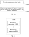
- FIG. 10 is a flowchart of a manufacturing method for a pressure relief apparatus 24 according to some embodiments of the present application.
- the manufacturing method for a pressure relief apparatus 24 according to the embodiments of the present application includes:
- FIG. 11 is a schematic block diagram of a manufacturing device 2000 for a pressure relief apparatus 24 according to some embodiments of the present application.
- the embodiments of the present application further provide a manufacturing device 2000 for a pressure relief apparatus 24.
- the manufacturing device 2000 includes a provision apparatus 2100 and a machining apparatus 2200.
- the provision apparatus 2100 is configured to provide a pressure relief body 241, where the pressure relief body 241 has a first surface 2411 and a second surface 2412 oppositely disposed in its thickness direction Z.
- the machining apparatus 2200 is configured to machine a pressure relief groove 242 on each of the first surface 2411 and the second surface 2412, so that the pressure relief groove 242 on the first surface 2411 and the pressure relief groove 242 on the second surface 2412 are oppositely disposed in the thickness direction Z of the pressure relief apparatus 24, a weak portion 2413 is formed between the pressure relief groove 242 on the first surface 2411 and the pressure relief groove 242 on the second surface 2412, and the weak portion 2413 is configured to rupture when a pressure or temperature inside a battery cell 20 reaches a threshold, so as to release the pressure inside the battery cell 20.
Landscapes
- Chemical & Material Sciences (AREA)
- Chemical Kinetics & Catalysis (AREA)
- Electrochemistry (AREA)
- General Chemical & Material Sciences (AREA)
- Engineering & Computer Science (AREA)
- General Engineering & Computer Science (AREA)
- Mechanical Engineering (AREA)
- Gas Exhaust Devices For Batteries (AREA)
Abstract
Description
- The present application relates to the field of battery technology, and particularly to a pressure relief apparatus, a battery cell, a battery, and a power consumption device.
- With the development of new energy technologies, batteries are increasingly widely used, for example, in mobile phones, notebook computers, scooters, electric vehicles, electric airplanes, electric ships, electric toy cars, electric toy boats, electric toy planes, and electric tools.
- In the development of battery technology, in addition to improving the performance of battery cells, safety is also an issue that needs to be considered. Therefore, how to improve the safety of battery cells is an urgent problem to be solved in the battery technology.
- Embodiments of the present application provide a pressure relief apparatus, a battery cell, a battery, and a power consumption device, where the safety of the battery cell can be effectively improved.
- In a first aspect, an embodiment of the present application provides a pressure relief apparatus, applied in a battery cell, and including: a pressure relief body having a first surface and a second surface oppositely disposed in a thickness direction thereof; and two pressure relief grooves oppositely disposed in the thickness direction and disposed on the first surface and the second surface separately, where a weak portion is formed between the two pressure relief grooves, and the weak portion is configured to rupture when a pressure or a temperature inside the battery cell reaches a threshold, so as to release the pressure inside the battery cell.
- In the foregoing technical solution, the pressure relief grooves are disposed on both the first surface and the second surface of the pressure relief body to obtain a relatively low residual thickness and reduce a thickness of the weak portion, so that the weak portion is prone to rupture to reduce a detonation pressure of the pressure relief apparatus, and the pressure relief body can release pressure in a timely manner to reduce risks of fire, explosion, and the like in the battery cell and effectively improve the safety of the battery cell.
- In some embodiments, a distance between the first surface and the second surface is a first distance, and a ratio of a minimum thickness of the weak portion to the first distance is 0.12-0.5. If the ratio of the minimum thickness of the weak portion to the first distance is too small, the minimum thickness of the weak portion is smaller, and the weak portion will rupture in a forming process. Even if the weak portion does not rupture, because the strength of the pressure relief body is low, the weak portion is prone to rupture to release pressure in a vibration environment or in a case that the pressure or the temperature inside the battery cell is far from the threshold, which affects the service life of the battery cell. If the ratio of the minimum thickness of the weak portion to the first distance is too large, the minimum thickness of the weak portion is larger, and the weak portion will not rupture to release pressure when the pressure or temperature inside the battery cell of the weak portion has reached the threshold, and untimely pressure relief will cause accidents such as fire and explosion of the battery cell. Therefore, the ratio of the minimum thickness of the weak portion to the first distance is set to 0.12-0.5, which not only ensures that the pressure relief apparatus can release pressure in a timely manner when the pressure inside the battery cell reaches the threshold, but can also ensure that the pressure relief apparatus has sufficient strength before pressure relief.
- In some embodiments, the pressure relief groove extends in a circumferential direction of the pressure relief body and confines a pressure relief portion; and the pressure relief portion is configured to open with the weak portion as a boundary when the pressure or temperature inside the battery cell reaches the threshold, so as to release the pressure inside the battery cell. This structure effectively increases a pressure relief area of the pressure relief apparatus, further increases a pressure relief rate of the pressure relief apparatus, reduces the risks of fire, explosion, and the like in the battery cell, and improves the safety of the battery cell.
- In some embodiments, there is a distance between two ends of the pressure relief groove in the circumferential direction of the pressure relief body. In this case, when the weak portion ruptures to release pressure, the area between the two ends of the pressure relief groove does not rupture, so that the pressure relief portion opens in an outward flipping manner, and the pressure relief portion is prevented from falling off as a whole during pressure relief.
- In some embodiments, the pressure relief groove is in an arc shape extending in the circumferential direction of the pressure relief body. The shape of the pressure relief groove with this structure is regular, so that the pressure relief portion is easy to machine and can open regularly during pressure relief.
- In some embodiments, the pressure relief body further has an outer surface and an inner surface, the outer surface is oppositely disposed to the inner surface in the thickness direction, and the pressure relief portion is configured to open from the inner surface towards the outer surface when the pressure or the temperature inside the battery cell reaches the threshold; and the pressure relief body is provided with a concave portion, the concave portion is recessed, in the thickness direction, from the outer surface in a direction towards the inner surface, and a bottom surface of the concave portion forms the first surface. The concave portion can provide a space for avoidance when the pressure relief portion opens outwards, and even if there is an obstacle on the outer surface of the pressure relief body, the pressure relief portion can open normally, thereby reducing a risk of being unable to open the pressure relief portion due to abutment of the obstacle against the outer surface.
- In some embodiments, a convex portion protruding from the inner surface is formed at a position, corresponding to the concave portion, of the pressure relief body, and a face, away from the inner surface, of the convex portion forms the second surface in the thickness direction. The convex portion can improve the strength of the area where the concave portion is disposed in the pressure relief body, and avoid a problem of low partial strength caused by the concave portion in the pressure relief body.
- In some embodiments, the pressure relief groove includes: two groove side surfaces facing each other along a width direction of the pressure relief groove; and a groove bottom surface connected to the two groove side surfaces, where the weak portion is formed in an area between the groove bottom surfaces of the two pressure relief grooves. The pressure relief groove of this structure is easy to machine and form, and the pressure relief groove may be formed by stamping.
- In some embodiments, the groove bottom surface is an arc surface recessed in a depth direction of the pressure relief groove. With this structure, the weak portion is of a structure with gradually decreasing thickness from two sides to a middle position, the weak portion can rupture more easily from the weakest position in the middle during pressure relief, and the pressure relief apparatus can rupture to release pressure in a timely manner when the pressure or temperature inside the battery cell reaches the threshold.
- In some embodiments, the groove bottom surface comprises a bottom plane and arc chamfer surfaces, and the bottom plane is connected to each of the groove side surfaces through one of the arc chamfer surfaces. This structure enables the middle area of the weak portion (the area, corresponding to the bottom plane, of the weak portion) to be the weakest, enables the weak portion to be prone to rupture, and ensures that the weak portion can rupture to release pressure in a timely manner when the pressure or temperature inside the battery cell reaches the threshold.
- In some embodiments, a distance between the two groove side surfaces gradually decreases in the depth direction of the pressure relief groove. This structure can effectively reduce the width of the weak portion, so that the weak portion is prone to rupture when the pressure or temperature inside the battery cell reaches the threshold.
- In some embodiments, an anti-oxidation layer is formed on the surface of the pressure relief body, and the anti-oxidation layer extends along a wall surface of the pressure relief groove in an area where the pressure relief groove is disposed. The anti-oxidation layer protects the pressure relief body to avoid oxidation of the pressure relief body. Of course, due to the extension of the anti-oxidation layer along the wall surface of the pressure relief groove in the area where the pressure relief groove is disposed, the anti-oxidation layer can also protect the area where the pressure relief groove is disposed in the pressure relief body, thereby reducing the risk of reduced strength of the weak portion due to oxidation of the pressure relief body in the area where the pressure relief groove is disposed.
- In some embodiments, a thickness of the anti-oxidation layer in the area of the pressure relief groove is smaller than that of the anti-oxidation layer in remaining areas. This reduces an impact of the anti-oxidation layer in the area of the pressure relief groove on the weak portion and ensures that the weak portion can rupture to release pressure in a timely manner when the pressure or temperature inside the battery cell reaches the threshold.
- In a second aspect, an embodiment of the present application provides a battery cell, including; an electrode assembly; and a shell, configured for accommodating the electrode assembly, where the shell includes the pressure relief apparatus provided in any of the foregoing embodiments of the first aspect.
- In some embodiments, the shell further includes a shell body, the shell body is configured for accommodating the electrode assembly, the shell body has an opening, and the pressure relief body is configured for covering the opening.
- In a third aspect, an embodiment of the present application provides a battery, including: the battery cell provided in any of the foregoing embodiments of the second aspect; and a box body configured for accommodating the battery cell.
- In a fourth aspect, an embodiment of the present application provides a power consumption device, including the battery provided in any of the foregoing embodiments of the third aspect.
- In a fifth aspect, an embodiment of the present application provides a manufacturing method for a pressure relief apparatus, including: providing a pressure relief body, where the pressure relief body has a first surface and a second surface oppositely disposed in a thickness direction thereof; and machining a pressure relief groove on each of the first surface and the second surface, so that the pressure relief groove on the first surface and the pressure relief groove on the second surface are oppositely disposed in the thickness direction of the pressure relief apparatus, a weak portion is formed between the pressure relief groove on the first surface and the pressure relief groove on the second surface, and the weak portion is configured to rupture when a pressure or a temperature inside a battery cell reaches a threshold, so as to release the pressure inside the battery cell.
- In a sixth aspect, an embodiment of the present application further provides a manufacturing device for a pressure relief apparatus, including: a provision apparatus, configured to provide a pressure relief body, where the pressure relief body has a first surface and a second surface oppositely disposed in a thickness direction thereof; and a machining apparatus, configured to machine a pressure relief groove on each of the first surface and the second surface, so that the pressure relief groove on the first surface and the pressure relief groove on the second surface are oppositely disposed in the thickness direction of the pressure relief apparatus, a weak portion is formed between the pressure relief groove on the first surface and the pressure relief groove on the second surface, and the weak portion is configured to rupture when a pressure or a temperature inside a battery cell reaches a threshold, so as to release the pressure inside the battery cell.
- In order to illustrate the technical solutions in the embodiments of the present application more clearly, brief description will be made below to the drawings required in the embodiments. It should be understood that the following drawings show only some embodiments of the present application and should not be regarded as limiting the scope, and other relevant drawings may be obtained based on these drawings by those of ordinary skill in the art without any creative efforts.
-
FIG. 1 is a structural schematic diagram of a vehicle according to some embodiments of the present application; -
FIG. 2 is an exploded view of a battery according to some embodiments of the present application; -
FIG. 3 is an exploded view of a battery cell according to some embodiments of the present application; -
FIG. 4 is a structural schematic diagram of a pressure relief apparatus shown inFIG. 3 ; -
FIG. 5 is a partial view of the pressure relief apparatus shown inFIG. 4 ; -
FIG. 6 is an A-A cross-sectional view of the pressure relief apparatus shown inFIG. 4 ; -
FIG. 7 is a partially enlarged view of the pressure relief apparatus according to some embodiments of the present application; -
FIG. 8 is a partially enlarged view of the pressure relief apparatus according to the other embodiments of the present application; -
FIG. 9 is a partially cross-sectional view of the pressure relief apparatus according to the other embodiments of the present application; -
FIG. 10 is a flowchart of a manufacturing method for a pressure relief apparatus according to some embodiments of the present application; and -
FIG. 11 is a schematic block diagram of a manufacturing device for a pressure relief apparatus according to some embodiments of the present application. - Marking description: 10 - box body; 11 - first portion; 12 - second portion; 20 - battery cell; 21 - electrode assembly; 22 - shell; 23 - end cover; 24 - pressure relief apparatus; 241 - pressure relief body; 2411 - first surface; 2412 - second surface; 2413 - weak portion; 2414 - pressure relief portion; 2415 - outer surface; 2415a - concave portion; 2415b - welding groove; 2416 - inner surface; 2416a - convex portion; 2416b - protrusion; 2417 - anti-oxidation layer; 242 - pressure relief groove; 2421 - groove side surface; 2422 - groove bottom surface; 2422a - bottom plane; 2422b - arc chamfer surface; 25 - electrode terminal; 26 - current collecting member; 100 - battery; 200 - controller; 300 - motor; 1000 - vehicle; 2000 - manufacturing device; 2100 - provision apparatus; 2200 - machining apparatus; X - width direction; Y - circumferential direction; Z - thickness direction.
- In order to make the objectives, technical solutions and advantages of the embodiments of the present application clearer, the technical solutions in the embodiments of the present application will be described clearly below with reference to the drawings in the embodiments of the present application. It will be apparent that, the described embodiments are some of the embodiments of the present application, not all of them. All other embodiments obtained by those of ordinary skill in the art based on the embodiments of the present application without creative efforts shall fall within the scope of protection of the present application.
- Unless otherwise defined, all technological and scientific terms used in the present application have the same meanings as those commonly understood by those skilled in the art to which the present application belongs. The terms used in the specification of the present application are merely for the purpose of describing specific embodiments, but are not intended to limit the present application. The terms "include" and "have" and any variations thereof in the specification and claims of the present application as well as the brief description of the drawings described above are intended to cover non-exclusive inclusion. In the specification and claims of the present application or in the foregoing drawings, the terms "first", "second", and the like are used to distinguish different objects and are not used to describe a specific sequence or a primary and secondary relation.
- The "embodiment" mentioned in the present application means that specific features, structures or characteristics described in conjunction with the embodiment may be included in at least one embodiment of the present application. The phrase at various locations in the specification does not necessarily refer to the same embodiment, or an independent or alternative embodiment exclusive of another embodiment.
- In the description of the present application, it should be noted that, unless otherwise specified and defined, the terms "mounted", "connected", "connection", and "attached" should be generally understood, for example, the "connection" may be a fixed connection, a detachable connection, an integral connection, a direct connection, or an indirect connection through a medium, or an internal communication of two elements. Those of ordinary skill in the art may appreciate the specific meanings of the foregoing terms in the present application to specific circumstances.
- The term "and/or" in the present application describes only an association relationship for describing associated objects and represents that three relationships may exist. For example, A and/or B may represent the following three cases: Only A exists, both A and B exist, and only B exists. In addition, the character "/" in the present application generally indicates an "or" relationship between successive associated objects.
- In the embodiments of the present application, the same reference numerals represent the same components, and for simplicity, detailed descriptions of the same components are omitted in different embodiments. It should be understood that dimensions such as thickness, length and width of various components and dimensions such as overall thickness, length and width of integrated apparatuses in the embodiments of the present application shown in the drawings are merely illustrative examples and should not constitute any limitations on the present application.
- In the present application, the term "a plurality of" means two (inclusive) or more.
- In the present application, battery cells may include lithium-ion secondary batteries, lithium-ion primary batteries, lithium-sulfur batteries, sodium lithium-ion batteries, sodium-ion batteries, magnesium-ion batteries, or the like, which are not limited by the embodiments of the present application. The battery cells may also be cylindrical, flat, cuboid, or in other shapes, which are not limited by the embodiments of the present application. The battery cells are generally divided into three types according to the way of packaging: cylindrical battery cells, square battery cells, and soft package battery cells, which are not limited in the embodiments of the present application.
- The battery mentioned in the embodiments of the present application refers to a single physical module that includes one or more battery cells to provide a higher voltage and capacity. For example, the battery mentioned in the present application may include a battery module or a battery pack. The battery generally includes a box body for packaging one or more battery cells. The box body may prevent liquid or other foreign matters from affecting the charging or discharging of the battery cells.
- The battery cell includes an electrode assembly and an electrolyte, and the electrode assembly is composed of a positive electrode sheet, a negative electrode sheet and a separator. The operation of the battery cell mainly relies on the movement of metal ions between the positive electrode sheet and the negative electrode sheet. The positive electrode sheet includes a positive electrode current collector and a positive electrode active material layer. The positive electrode active material layer is coated on a surface of the positive electrode current collector, and the positive electrode current collector not coated with the positive electrode active material layer protrudes from the positive electrode current collector coated with the positive electrode active material layer and is used as a positive tab. In an example of a lithium-ion battery, a material of the positive electrode current collector may be aluminum, and a positive electrode active material may be lithium cobalt oxide, lithium iron phosphate, ternary lithium, lithium manganate oxide, or the like. The negative electrode sheet includes a negative electrode current collector and a negative electrode active material layer. The negative electrode active material layer is coated on a surface of the negative electrode current collector, and the negative electrode current collector not coated with the negative electrode active material layer protrudes from the negative electrode current collector coated with the negative electrode active material layer and is used as a negative tab. A material of the negative electrode current collector may be copper, and a negative electrode active material may be carbon, silicon, or the like. In order to ensure that no fusing occurs when a large current passes through, there are a plurality of positive tabs which are stacked together and a plurality of negative tabs which are stacked together. A material of the separator may be polypropylene (PP), polyethylene (PE), or the like. In addition, the electrode assembly may be of a winding structure or a laminated structure, and the embodiments of the present application are not limited thereto.
- The development of battery technologies need to simultaneously consider many design factors, such as energy density, cycle life, discharge capacity, charge and discharge rate, and other performance parameters. In addition, the safety of the battery should also be considered.
- To ensure the safety of a battery cell, a pressure relief apparatus is generally disposed inside the battery cell. When a pressure or temperature inside the battery cell reaches a threshold, the pressure inside the battery cell is released through the pressure relief apparatus to ensure the safety of the battery cell.
- The inventor noticed that even if the pressure relief apparatus is disposed inside the battery cell, safety issues such as fire and explosion may still occur. The inventor found through further research that, in related technologies, a pressure relief groove is generally disposed on a pressure relief body of the pressure relief apparatus, and during pressure relief, the pressure relief body ruptures from a position where the pressure relief groove is disposed to achieve a purpose of pressure relief. The inventor found through in-depth research that the pressure relief groove is generally disposed on a single side of the pressure relief body; and to meet design requirements and ensure timely pressure relief when the pressure or temperature inside the battery cell reaches the threshold, the pressure relief groove should be machined to a certain depth, so that a residual thickness of the pressure relief body after the pressure relief groove is disposed will not be too thick, but limited by a machining technology and a material of the pressure relief body, in a case that the pressure relief body is thick and/or the material of the pressure relief body is hard, the residual thickness barely meets the design requirements if the pressure relief groove is machined on the single side of the pressure relief body, so that a detonation pressure of the pressure relief apparatus is high, and the pressure relief apparatus cannot release pressure when it is supposed to release pressure and therefore cannot release the pressure inside the battery cell in a timely manner, resulting in safety issues such as fire and explosion of the battery cell.
- In view of this, the embodiments of the present application provide a pressure relief apparatus, where a pressure relief groove is disposed on both a first surface and a second surface of a pressure relief body that are opposite, a weak portion is formed between the pressure relief groove on the first surface and the pressure relief groove on the second surface, and the weak portion is configured to rupture when a pressure or temperature inside a battery cell reaches a threshold to release the pressure inside the battery cell.
- In such a pressure relief apparatus, the pressure relief groove is disposed on both the first surface and the second surface of the pressure relief body to obtain a relatively low residual thickness and reduce a thickness of the weak portion, so that the weak portion is prone to rupture to reduce a detonation pressure of the pressure relief apparatus, and the pressure relief body can release pressure in a timely manner to reduce risks of fire, explosion, and the like in the battery cell and effectively improve the safety of the battery cell.
- In addition, because the pressure relief groove is disposed on both the first surface and the second surface of the pressure relief body, difficulties in forming can be effectively reduced, machining accuracy can be ensured, the thickness of the weak portion can be accurately controlled, and the thickness of the weak portion meets the detonation requirements.
- The pressure relief apparatus described in the embodiments of the present application is applicable to battery cells, batteries, and power consumption devices using batteries.
- The power consumption devices may be vehicles, mobile phones, portable devices, notebook computers, ships, spacecrafts, electric toys, electric tools, and the like. The vehicles may be oil-fueled vehicles, gas-fueled vehicles, or new energy vehicles, and the new energy vehicles may be pure electric vehicles, hybrid electric vehicles, extended range vehicles, or the like; the spacecrafts include airplanes, rockets, space shuttles, spaceships, and the like; the electric toys include fixed or mobile electric toys, such as game consoles, electric car toys, electric boat toys, and electric plane toys; and the electric tools include electric metal cutting tools, electric grinding tools, electric assembly tools, and railway electric tools, such as electric drills, electric grinders, electric wrenches, electric screwdrivers, electric hammers, electric impact drills, concrete vibrators, and electric planers. The embodiments of the present application do not impose special limitations on the foregoing power consumption devices.
- For convenient description, the following embodiments are described by an example of a vehicle as a power consumption device.
- Refer to
FIG. 1. FIG. 1 is a structural schematic diagram of avehicle 1000 according to some embodiments of the present application. Abattery 100 is disposed inside thevehicle 1000, and thebattery 100 may be disposed at a bottom, head, or tail of thevehicle 1000. Thebattery 100 may be used for supplying power to thevehicle 1000. For example, thebattery 100 may be used as an operation power supply of thevehicle 1000. - The
vehicle 1000 may further include acontroller 200 and amotor 300. Thecontroller 200 is used for controlling thebattery 100 to supply power to themotor 300, for example, for the working power demand of thevehicle 1000 during startup, navigation and running. - In some embodiments of the present application, the
battery 100 may be used not only as an operation power supply of thevehicle 1000, but also as a driving power supply of thevehicle 1000 to replace or partially replace fuel or natural gas to provide driving power for thevehicle 1000. - Refer to
FIG. 2. FIG. 2 is an exploded view of abattery 100 according to some embodiments of the present application. Thebattery 100 includes abox body 10 andbattery cells 20, where thebox body 10 is used for accommodating thebattery cells 20. - The
box body 10 is a component that accommodates thebattery cells 20, thebox body 10 provides a space for thebattery cells 20, and thebox body 10 may have various structures. In some embodiments, thebox body 10 may include a first portion 11 and a second portion 12, and the first portion 11 and the second portion 12 cover each other to confine the space for accommodating thebattery cells 20. The first portion 11 and the second portion 12 may be in various shapes, such as cuboid or cylindrical. The first portion 11 may be of a hollow structure with an open side, the second portion 12 may also be of a hollow structure with an open side, and the open side of the second portion 12 covers the open side of the first portion 11 to form thebox body 10 with the accommodating space. Alternatively, the first portion 11 is of a hollow structure with an open side, the second portion 12 is of a plate-like structure, and the second portion 12 covers the open side of the first portion 11 to form thebox body 10 with the accommodating space. The first portion 11 and the second portion 12 may be sealed through a sealing element, which may be a sealing ring, a sealant, or the like. - There may be one or
more battery cells 20 in thebattery 100. If there is a plurality ofbattery cells 20, the plurality ofbattery cells 20 may be connected in series, parallel, or series-parallel. The series-parallel connection refers to both series and parallel connection in the plurality ofbattery cells 20. The plurality ofbattery cells 20 may be first connected in series, parallel, or series-parallel to form a battery module, and then a plurality of battery modules may be connected in series, parallel, or series-parallel to form a whole accommodated in thebox body 10. Alternatively, all thebattery cells 20 may be directly connected in series, parallel, or series-parallel together, and then the whole formed by all thebattery cells 20 is accommodated in thebox body 10. - In some embodiments, the
battery 100 may further include a converging component, and the plurality ofbattery cells 20 may be electrically connected through the converging component to implement the series, parallel, or series-parallel connection of the plurality ofbattery cells 20. The converging component may be a metal conductor, such as copper, iron, aluminum, stainless steel, or aluminum alloy. - Refer to
FIG. 3. FIG. 3 is an exploded view of abattery cell 20 according to some embodiments of the present application. Thebattery cell 20 may include a shell and anelectrode assembly 21, where the shell is used for accommodating theelectrode assembly 21. The shell may include ashell body 22, anend cover 23, and apressure relief apparatus 24. - The
shell body 22 is a component used for accommodating theelectrode assembly 21, and theshell body 22 may be of a hollow structure with an opening formed at one end, or theshell body 22 may be of a hollow structure with openings formed at two opposite ends. Theshell body 22 may be in various shapes, such as cylindrical or cuboid. A material of theshell body 22 may be various, such as copper, iron, aluminum, steel, or aluminum alloy. - The
electrode assembly 21 is a component that undergoes electrochemical reactions in thebattery cell 20. Theelectrode assembly 21 may include a positive electrode sheet, a negative electrode sheet, and a separator. Theelectrode assembly 21 may be of a winding structure formed by winding the positive electrode sheet, the separator, and the negative electrode sheet, or a stacked structure formed by stacking the positive electrode sheet, the separator, and the negative electrode sheet. Theelectrode assembly 21 has a positive tab and a negative tab, the positive tab may be a portion not coated with the positive electrode active material layer on the positive electrode sheet, and the negative tab may be a portion not coated with the negative electrode active material layer on the negative electrode sheet. - The
end cover 23 is a component that is configured to close to the opening of theshell body 22 to isolate an internal environment of thebattery cell 20 from an external environment. Theend cover 23 is closed to the opening of theshell body 22, and theend cover 23 and theshell body 22 jointly confine a sealed space for accommodating theelectrode assembly 21, an electrolyte, and other components. A shape of theend cover 23 may be adapted to that of theshell body 22. For example, theshell body 22 is of a cuboid structure, and theend cover 23 is of a rectangular plate structure matching theshell body 22. For another example, theshell body 22 is of a cylindrical structure, and theend cover 23 is of a circular plate structure matching theshell body 22. Theend cover 23 may be made of various materials, such as copper, iron, aluminum, steel, or aluminum alloy. - There is one or two end covers 23 in the
battery cell 20. If theshell body 22 is of a hollow structure with an opening formed at one end, oneend cover 23 is correspondingly disposed. If theshell body 22 is of a hollow structure with openings formed at two ends, two end covers 23 are correspondingly disposed, and the two end covers 23 are closed to the two openings of theshell body 22 separately. - An
electrode terminal 25 may be disposed in the battery cell, theelectrode terminal 25 may be disposed on theend cover 23 or theshell body 22, and theelectrode terminal 25 is used for electrical connection with theelectrode assembly 21 to output electrical energy of thebattery cell 20. In an embodiment where there are two end covers 23 in thebattery cell 20, theelectrode terminal 25 may be disposed on the two end covers 23, theelectrode terminal 25 on oneend cover 23 is electrically connected to the positive tab of theelectrode assembly 21, and theelectrode terminal 25 on the other end cover 23 is electrically connected to the negative tab of theelectrode assembly 21. As shown inFIG. 3 , in an embodiment where there is oneend cover 23 in thebattery cell 20, theelectrode terminal 25 may be disposed on only the shell, theelectrode terminal 25 may be electrically connected to the positive tab of theelectrode assembly 21, and theend cover 23 is electrically connected to the negative tab of theelectrode assembly 21. - A current collecting
member 26 may be further disposed in thebattery cell 20 to achieve the electrical connection between theelectrode terminal 25 and the tab or theend cover 23 and the tab. For example, there is oneend cover 23 in thebattery cell 20, theelectrode terminal 25 on theshell body 22 is connected to the positive tab of theelectrode assembly 21 by means of a current collectingmember 26, and theend cover 23 is connected to the negative tab of theelectrode assembly 21 by means of another current collectingmember 26. - The
pressure relief apparatus 24 is a component that releases the pressure inside thebattery cell 20. When the pressure or temperature inside thebattery cell 20 reaches a threshold, the pressure inside thebattery cell 20 is released through thepressure relief apparatus 24. A specific structure of thepressure relief apparatus 24 will be explained in detail below with reference to the accompanying drawings. - Refer to
FIG. 4 and FIG. 5. FIG. 4 is a structural schematic diagram of thepressure relief apparatus 24 shown inFIG. 3 , andFIG. 5 is a partial view of thepressure relief apparatus 24 shown inFIG. 4 . An embodiment of the present application provides apressure relief apparatus 24 used for abattery cell 20. Thepressure relief apparatus 24 includes apressure relief body 241 and twopressure relief grooves 242. Thepressure relief body 241 has afirst surface 2411 and asecond surface 2412 oppositely disposed in its thickness direction Z. The twopressure relief grooves 242 are oppositely disposed in the thickness direction Z of thepressure relief apparatus 24 and disposed on thefirst surface 2411 and thesecond surface 2412 separately. Aweak portion 2413 is formed between the twopressure relief grooves 242, and theweak portion 2413 is configured to rupture when the pressure or temperature inside thebattery cell 20 reaches a threshold to release the pressure inside thebattery cell 20. - The
pressure relief body 241 may be either at theend cover 23 or theshell body 22. Thepressure relief body 241 may be an independent component mounted on theend cover 23, or an independent component mounted on theshell body 22, such as an explosion-proof valve or a rupture disc. A shape of thepressure relief body 241 may be various. For example, thepressure relief body 241 is theend cover 23, and thepressure relief body 241 may be rectangular, circular, or the like. For example, thepressure relief body 241 is made of a hard material, and a tensile strength of thepressure relief body 241 is 108 MPa to 384 MPa steel. Thepressure relief body 241 may be made of a metal material, such as copper, iron, aluminum, steel, or aluminum alloy. - In the
battery cell 20, thefirst surface 2411 of thepressure relief body 241 may be an outermost surface of thepressure relief body 241, or a step surface at a distance from the outermost surface of thepressure relief body 241 and towards an outer side of thebattery cell 20. Thesecond surface 2412 of thepressure relief body 241 may be an innermost surface of thepressure relief body 241, or a step surface at a distance from the innermost surface of thepressure relief body 241 and towards an inner side of thebattery cell 20. For example, thefirst surface 2411 and thesecond surface 2412 are planes parallel to each other. - In the embodiments of the present application, the number of
pressure relief grooves 242 on thefirst surface 2411 and thesecond surface 2412 is not limited, and there may be one or morepressure relief grooves 242 on thefirst surface 2411 and thesecond surface 2412, as long as the pressure relief groove(s) 242 on thefirst surface 2411 corresponds to the pressure relief groove(s) 242 on thesecond surface 2412 one to one. Thepressure relief groove 242 may be formed in various ways, such as stamping or milling, which is not specially limited by the embodiments of the present application. Thepressure relief groove 242 may be a straight groove extending along a straight line, or a bent groove or arc groove extending in a circumferential direction Y of thepressure relief body 241, where the bent groove may be a polygonal groove, such as a rectangular groove. - The
weak portion 2413 is a portion of thepressure relief body 241 located between twopressure relief grooves 242, namely, a residual portion of an area where thepressure relief groove 242 is disposed in thepressure relief body 241. - In the embodiments of the present application, the
pressure relief groove 242 is disposed on both thefirst surface 2411 and thesecond surface 2412 of thepressure relief body 241 to obtain a relatively low residual thickness and reduce a thickness of theweak portion 2413, so that theweak portion 2413 is prone to rupture to reduce a detonation pressure of thepressure relief apparatus 24, and thepressure relief body 241 can release pressure in a timely manner to reduce risks of fire, explosion, and the like in thebattery cell 20 and effectively improve the safety of thebattery cell 20. - In some embodiments, a distance between the
first surface 2411 and thesecond surface 2412 is a first distance, and a ratio of a minimum thickness of theweak portion 2413 to the first distance is 0.12-0.5. - The first distance is a thickness of the
pressure relief body 241 in an area between thefirst surface 2411 and thesecond surface 2412. Theweak portion 2413 may be of an equal thickness structure in any area, or a variable thickness structure in a plurality of areas. "The minimum thickness of theweak portion 2413" does not limit theweak portion 2413 to a thickened structure. When theweak portion 2413 is of the equal thickness structure, the thickness at any position of theweak portion 2413 is the minimum thickness, and the minimum thickness of theweak portion 2413 is also a maximum thickness of theweak portion 2413. - If the ratio of the minimum thickness of the
weak portion 2413 to the first distance is too small, the minimum thickness of theweak portion 2413 is smaller, and theweak portion 2413 will rupture in a forming process. Even if theweak portion 2413 does not rupture, because the strength of thepressure relief body 241 is low, theweak portion 2413 is prone to rupture to release pressure in a vibration environment or in a case that the pressure or temperature inside thebattery cell 20 is far from the threshold, which affects the service life of thebattery cell 20. If the ratio of the minimum thickness of theweak portion 2413 to the first distance is too large, the minimum thickness of theweak portion 2413 is larger, and theweak portion 2413 will not rupture to release pressure when the pressure or temperature inside thebattery cell 20 of theweak portion 2413 has reached the threshold, and untimely pressure relief will cause accidents such as fire and explosion of thebattery cell 20. - In this embodiment, the ratio of the minimum thickness of the
weak portion 2413 to the first distance is set to 0.12-0.5, which not only ensures that thepressure relief apparatus 24 can release pressure in a timely manner when the pressure inside thebattery cell 20 reaches the threshold, but can also ensure that thepressure relief apparatus 24 has sufficient strength before pressure relief. - In some embodiments, the
pressure relief groove 242 extends in the circumferential direction Y of thepressure relief body 241 and confines apressure relief portion 2414. Thepressure relief portion 2414 is configured to open with theweak portion 2413 as a boundary when the pressure or temperature inside thebattery cell 20 reaches the threshold, so as to release the pressure inside thebattery cell 20. - The
pressure relief groove 242 may be of a closed loop structure that extends in the circumferential direction Y of thepressure relief body 241 and is connected end to end, for example, thepressure relief groove 242 is circular, elliptical, rectangular, or the like. Thepressure relief groove 242 may alternatively be a non-closed loop structure that extends in the circumferential direction Y of thepressure relief body 241 and has two ends at a distance, for example, thepressure relief groove 242 is in a shape of "C", "U" with a rightward opening, or the like. - The
pressure relief portion 2414 is an area confined by thepressure relief groove 242 on thepressure relief body 241, and theweak portion 2413 is located at an edge of thepressure relief portion 2414. When the pressure or temperature inside thebattery cell 20 reaches the threshold, theweak portion 2413 ruptures, so that thepressure relief portion 2414 opens with theweak portion 2413 as the boundary. After thepressure relief portion 2414 opens, an opening portion will be formed at a position of thepressure relief body 241 corresponding to thepressure relief portion 2414, and emissions (gas, electrolyte, and the like) inside thebattery cell 20 may be discharged through the opening portion to achieve the purpose of releasing the pressure inside thebattery cell 20. In the opening process of thepressure relief portion 2414, thepressure relief portion 2414 may open by detaching from thepressure relief body 241, or by flipping from the inside out. - In this embodiment, the
pressure relief groove 242 extends in an axial direction of thepressure relief body 241 and confines thepressure relief portion 2414, thereby effectively increasing a pressure relief area of thepressure relief apparatus 24, further increasing a pressure relief rate of thepressure relief apparatus 24, reducing the risks of fire, explosion, and the like in thebattery cell 20, and improving the safety of thebattery cell 20. - In some embodiments, there is a distance between two ends of the
pressure relief groove 242 in the circumferential direction Y of thepressure relief body 241. - There is the distance between the two ends of the
pressure relief groove 242 in the circumferential direction Y of thepressure relief body 241, that is, there is the distance between the two ends of thepressure relief groove 242 in its extension direction. It may be understood that thepressure relief groove 242 is of the non-closed structure with the two ends at the distance. - In this embodiment, there is the distance between the two ends of the
pressure relief groove 242 in the circumferential direction Y of thepressure relief body 241. When theweak portion 2413 ruptures to release pressure, the area between the two ends of thepressure relief groove 242 does not rupture, so that thepressure relief portion 2414 opens in an outward flipping manner, and thepressure relief portion 2414 is prevented from falling off as a whole during pressure relief. - In some embodiments, the
pressure relief groove 242 is in an arc shape extending in the circumferential direction Y of thepressure relief body 241. - As shown in
FIG. 2 , a circularpressure relief body 241 is used as an example, and thepressure relief groove 242 may be coaxial with thepressure relief body 241. - For example, a central angle of the
pressure relief groove 242 is not less than 180°. Preferably, the central angle of thepressure relief groove 242 is greater than 270°. - In this embodiment, the
pressure relief groove 242 is arc-shaped, and the shape of thepressure relief groove 242 with this structure is regular, so that thepressure relief portion 2414 is easy to machine and can open regularly during pressure relief. - In some embodiments, with continued reference to
FIG. 5 , thepressure relief body 241 further has anouter surface 2415 and aninner surface 2416, theouter surface 2415 is opposite to theinner surface 2416 in the thickness direction Z of thepressure relief apparatus 24, and thepressure relief portion 2414 is configured to open from theinner surface 2416 to theouter surface 2415 when the pressure or temperature inside thebattery cell 20 reaches the threshold. Thepressure relief body 241 is provided with aconcave portion 2415a, theconcave portion 2415a is recessed from theouter surface 2415 to theinner surface 2416 in the thickness direction Z of thepressure relief apparatus 24, and a bottom surface of theconcave portion 2415a forms thefirst surface 2411. - In the
battery cell 20, theouter surface 2415 is a surface, facing the outer side of thebattery cell 20, of thepressure relief body 241, and theinner surface 2416 is a surface, facing the inner side of thebattery cell 20, of thepressure relief body 241. Theconcave portion 2415a is recessed from theouter surface 2415 to theinner surface 2416, the bottom surface of theconcave portion 2415a forms thefirst surface 2411, and thefirst surface 2411 is a step surface of thepressure relief body 241. A shape of theconcave portion 2415a may be various, such as circular, rectangular, or the like. - In the
battery cell 20, when the pressure or temperature inside thebattery cell 20 reaches the threshold, thepressure relief portion 2414 will open from theinner surface 2416 to theouter surface 2415, that is, thepressure relief portion 2414 will open from the inside of thebattery cell 20 to the outside. - In the thickness direction Z of the
pressure relief body 241, a distance between theouter surface 2415 and theinner surface 2416 is a second distance, which may be equal or unequal to the first distance. If the second distance is unequal to the first distance, the second distance may be greater than the first distance, or the second distance may be less than the first distance. - In this embodiment, the
pressure relief body 241 is provided with theconcave portion 2415a, theconcave portion 2415a can provide a space for avoidance when thepressure relief portion 2414 opens outwards, and even if there is an obstacle on theouter surface 2415 of thepressure relief body 241, thepressure relief portion 2414 can open normally, thereby reducing a risk of being unable to open thepressure relief portion 2414 due to abutment of the obstacle against theouter surface 2415. - In some embodiments, a
convex portion 2416a protruding from theinner surface 2416 is formed at a position, corresponding to theconcave portion 2415a, of thepressure relief body 241, and a face, away from theinner surface 2416, of theconvex portion 2416a forms thesecond surface 2412 in the thickness direction Z of thepressure relief apparatus 24. - A shape of the
convex portion 2416a may be adapted to that of theconcave portion 2415a. For example, theconcave portion 2415a is circular, and theconvex portion 2416a may be correspondingly circular. For another example, theconcave portion 2415a is rectangular, and theconvex portion 2416a may be correspondingly rectangular. Theconvex portion 2416a has a peripheral surface connected between thesecond surface 2412 and theinner surface 2416, and the peripheral surface is located at a periphery of theconcave portion 2415a. For example, both theconcave portion 2415a and theconvex portion 2416a are circular, theconcave portion 2415a is coaxial with theconvex portion 2416a, and a diameter of the peripheral surface of theconvex portion 2416a is greater than that of theconcave portion 2415a. - In actual production, the
concave portion 2415a may be formed on one side of thepressure relief body 241 by stamping, and theconvex portion 2416a may be correspondingly formed on the other side of thepressure relief body 241. - In this embodiment, the
convex portion 2416a protruding from theinner surface 2416 is formed at the position, corresponding to theconcave portion 2415a, of thepressure relief body 241, where theconvex portion 2416a can improve the strength of the area where theconcave portion 2415a is disposed in thepressure relief body 241, and avoid a problem of low partial strength caused by theconcave portion 2415a in thepressure relief body 241. - In some embodiments, refer to
FIG. 6. FIG. 6 is an A-A cross-sectional view of thepressure relief apparatus 24 shown inFIG. 4 . Awelding groove 2415b is further disposed on theouter surface 2415, aprotrusion 2416b protruding from theinner surface 2416 is formed at a position, corresponding to thewelding groove 2415b, of thepressure relief body 241, and both thewelding groove 2415b and theprotrusion 2416b are located at a periphery of theconvex portion 2416a. Theprotrusion 2416b is used for abutting against and welding with the current collectingmember 26. - For example, both the
welding groove 2415b and theprotrusion 2416b are of circular structures surrounding theconvex portion 2416a. - In this embodiment, the
pressure relief body 241 may be used as theend cover 23 in thebattery cell 20 to cover the opening of theshell body 22. When thepressure relief body 241 is welded with the current collectingmember 26, thepressure relief body 241 may be welded in the area of thewelding groove 2415b to weld theprotrusion 2416b with the current collectingmember 26 together, and a welding mark formed by welding theprotrusion 2416b with the current collectingmember 26 will be formed in thewelding groove 2415b. - In some embodiments, refer to
FIG. 7 and FIG. 8 , whereFIG. 7 is a partially enlarged view of thepressure relief apparatus 24 according to some embodiments of the present application, andFIG. 8 is a partially enlarged view of thepressure relief apparatus 24 according to the other embodiments of the present application. Thepressure relief groove 242 includes agroove bottom surface 2422 and two groove side surfaces 2421. The twogroove side surfaces 2421 face each other in a width direction X of thepressure relief groove 242. Thegroove bottom surface 2422 is connected to the two groove side surfaces 2421. Theweak portion 2413 is formed in an area between the groove bottom surfaces 2422 of the twopressure relief grooves 242. - The two
groove side surfaces 2421 of thepressure relief groove 242 may be parallel to each other or tilt towards each other. Thegroove bottom surface 2422 of thepressure relief groove 242 may be flat or curved. - In this embodiment, the
pressure relief groove 242 is easy to machine, and thepressure relief groove 242 may be formed by stamping. - In some embodiments, with reference to
FIG. 7 , thegroove bottom surface 2422 is an arc surface recessed in a depth direction of thepressure relief groove 242. - It may be understood that, for the
pressure relief groove 242 disposed on thefirst surface 2411, the depth direction of thepressure relief groove 242 is a direction from thefirst surface 2411 to thesecond surface 2412. For thepressure relief groove 242 disposed on thesecond surface 2412, the depth direction of thepressure relief groove 242 is a direction from thesecond surface 2412 to thefirst surface 2411. - In this embodiment, a distance between arc vertices of the groove bottom surfaces 2422 of the two
pressure relief grooves 242 is the minimum thickness of theweak portion 2413. - For example, the
groove bottom surface 2422 is tangent to the twogroove side surfaces 2421 of thepressure relief groove 242. - In this embodiment, the
groove bottom surface 2422 is the arc surface recessed in the depth direction of thepressure relief groove 242, so that theweak portion 2413 is of a structure with gradually decreasing thickness from two sides to a middle position, theweak portion 2413 can rupture more easily from the weakest position in the middle during pressure relief, and thepressure relief apparatus 24 can rupture to release pressure in a timely manner when the pressure or temperature inside thebattery cell 20 reaches the threshold. - In some embodiments, with reference to
FIG. 8 , thegroove bottom surface 2422 includes a bottom plane 2422a and arc chamfer surfaces 2422b, and the bottom plane 2422a is connected to eachgroove side surface 2421 through an arc chamfer surface 2422b. - In this embodiment, a distance between the bottom planes 2422a of the two
pressure relief grooves 242 is the minimum thickness of theweak portion 2413. - For example, both the bottom plane 2422a and the
groove side surface 2421 are tangent to the arc chamfer surfaces 2422b. In thepressure relief groove 242, the two arc chamfer surfaces 2422b connected to the twogroove side surfaces 2421 are symmetrically disposed in the width direction X of thepressure relief groove 242. - In this embodiment, the bottom plane 2422a is connected to each
groove side surface 2421 through an arc chamfer surface 2422b, so the machining is easy, and smooth transition is achieved between thegroove side surface 2421 and the bottom plane 2422a. This structure enables the middle area of the weak portion 2413 (the area, corresponding to the bottom plane 2422a, of the weak portion 2413) to be the weakest, enables theweak portion 2413 to be prone to rupture, and ensures that theweak portion 2413 can rupture to release pressure in a timely manner when the pressure or temperature inside thebattery cell 20 reaches the threshold. - In some embodiments, with continued reference to
FIG. 7 and FIG. 8 , a distance between the twogroove side surfaces 2421 gradually decreases in the depth direction of thepressure relief groove 242. - For example, the two
groove side surfaces 2421 of thepressure relief groove 242 are both inclined planes, and the twogroove side surfaces 2421 are symmetrically disposed in the width direction X of thepressure relief groove 242. - In this embodiment, the distance between the two
groove side surfaces 2421 gradually decreases in the depth direction of thepressure relief groove 242. This structure can effectively reduce the width of theweak portion 2413, so that theweak portion 2413 is prone to rupture when the pressure or temperature inside thebattery cell 20 reaches the threshold. - In some embodiments, refer to
FIG. 9. FIG. 9 is a partial cross-sectional view of thepressure relief apparatus 24 according to the other embodiments of the present application. Ananti-oxidation layer 2417 is formed on the surface of thepressure relief body 241, and theanti-oxidation layer 2417 extends along a wall surface of thepressure relief groove 242 in the area where thepressure relief groove 242 is disposed. - For example, the
anti-oxidation layer 2417 may be a metal coating located on the surface of thepressure relief body 241. For example, thepressure relief body 241 is a steel layer, and theanti-oxidation layer 2417 is a nickel layer plated on thepressure relief body 241. - The
anti-oxidation layer 2417 protects thepressure relief body 241 to avoid oxidation of thepressure relief body 241. It will be apparent that, due to the extension of theanti-oxidation layer 2417 along the wall surface of thepressure relief groove 242 in the area where thepressure relief groove 242 is disposed, theanti-oxidation layer 2417 can also protect the area where thepressure relief groove 242 is disposed in thepressure relief body 241, thereby reducing the risk of reduced strength of theweak portion 2413 due to oxidation of thepressure relief body 241 in the area where thepressure relief groove 242 is disposed. - In some embodiments, a thickness of the
anti-oxidation layer 2417 in the area of thepressure relief groove 242 is smaller than that of theanti-oxidation layer 2417 in remaining areas. - The remaining areas refer to areas except the area of the
pressure relief groove 242 in thepressure relief body 241. - For example, the thickness of the
anti-oxidation layer 2417 in an area corresponding to thegroove bottom surface 2422 of thepressure relief groove 242 is greater than that of theanti-oxidation layer 2417 in areas corresponding to thegroove side surfaces 2421 of thepressure relief groove 242 to improve oxidation resistance of theweak portion 2413. - In this embodiment, the thickness of the
anti-oxidation layer 2417 in the area of thepressure relief groove 242 is smaller than that of theanti-oxidation layer 2417 in the remaining areas, which reduces an impact of theanti-oxidation layer 2417 in the area of thepressure relief groove 242 on theweak portion 2413, and ensures that theweak portion 2413 can rupture to release pressure in a timely manner when the pressure or temperature inside thebattery cell 20 reaches the threshold. - An embodiment of the present application provides a
battery cell 20, including anelectrode assembly 21 and a shell for accommodating theelectrode assembly 21. The shell includes thepressure relief apparatus 24 provided by any of the foregoing embodiments. - In some embodiments, the shell further includes a
shell body 22, theshell body 22 is used for accommodating theelectrode assembly 21, theshell body 22 has an opening, and thepressure relief body 241 is used for covering the opening. - It may be understood that the
pressure relief body 241 is theend cover 23 in this embodiment. - An embodiment of the present application provides a
battery 100, including abox body 10 and thebattery cell 20 provided in any of the foregoing embodiments, where thebox body 10 is used for accommodating thebattery cell 20. - An embodiment of the present application provides a power consumption device, including the
battery 100 provided in any of the foregoing embodiments. - Moreover, with reference to
FIG. 4 and FIG. 5 , an embodiment of the present application provides apressure relief apparatus 24 for covering an opening of ashell body 22 of abattery cell 20. Thepressure relief apparatus 24 includes apressure relief body 241 and twopressure relief grooves 242. Thepressure relief body 241 is circular and has afirst surface 2411 and asecond surface 2412 oppositely disposed in its thickness direction Z. The twopressure relief grooves 242 are oppositely disposed in the thickness direction Z of thepressure relief body 241 and disposed on thefirst surface 2411 and thesecond surface 2412 separately, aweak portion 2413 is formed between the twopressure relief grooves 242, thepressure relief groove 242 extends in a circumferential direction Y of thepressure relief body 241 and confines apressure relief portion 2414, there is a distance between two ends of thepressure relief groove 242 in the circumferential direction Y of thepressure relief body 241, and thepressure relief portion 2414 is configured to open with theweak portion 2413 as a boundary when a pressure or temperature inside thebattery cell 20 reaches a threshold, so as to release the pressure inside thebattery cell 20. - In such a
pressure relief apparatus 24, thepressure relief groove 242 is disposed on both thefirst surface 2411 and thesecond surface 2412 of thepressure relief body 241 to obtain a relatively low residual thickness and reduce a thickness of theweak portion 2413, so that theweak portion 2413 is prone to rupture to reduce a detonation pressure of thepressure relief apparatus 24, and thepressure relief body 241 can release pressure in a timely manner to reduce risks of fire, explosion, and the like in thebattery cell 20 and effectively improve the safety of thebattery cell 20. In addition, when theweak portion 2413 ruptures to release pressure, the area between the two ends of thepressure relief groove 242 does not rupture, so that thepressure relief portion 2414 opens in an outward flipping manner, and thepressure relief portion 2414 is prevented from falling off as a whole during pressure relief. - Refer to
FIG. 10. FIG. 10 is a flowchart of a manufacturing method for apressure relief apparatus 24 according to some embodiments of the present application. The manufacturing method for apressure relief apparatus 24 according to the embodiments of the present application includes: - S100: Provide a
pressure relief body 241, where thepressure relief body 241 has afirst surface 2411 and asecond surface 2412 oppositely disposed in its thickness direction Z; and - S200: Machine a
pressure relief groove 242 on each of thefirst surface 2411 and thesecond surface 2412 of thepressure relief body 241, so that thepressure relief groove 242 on thefirst surface 2411 and thepressure relief groove 242 on thesecond surface 2412 are oppositely disposed in the thickness direction Z of thepressure relief apparatus 24, aweak portion 2413 is formed between thepressure relief groove 242 on thefirst surface 2411 and thepressure relief groove 242 on thesecond surface 2412, and theweak portion 2413 is configured to rupture when a pressure or temperature inside abattery cell 20 reaches a threshold, so as to release the pressure inside thebattery cell 20. - It should be noted that relevant structures of the
pressure relief apparatus 24 manufactured by the manufacturing method provided in the foregoing embodiments may be referenced to thepressure relief apparatus 24 provided in each foregoing embodiment, and will not be repeated here. - Refer to
FIG. 11. FIG. 11 is a schematic block diagram of amanufacturing device 2000 for apressure relief apparatus 24 according to some embodiments of the present application. The embodiments of the present application further provide amanufacturing device 2000 for apressure relief apparatus 24. Themanufacturing device 2000 includes a provision apparatus 2100 and a machining apparatus 2200. - The provision apparatus 2100 is configured to provide a
pressure relief body 241, where thepressure relief body 241 has afirst surface 2411 and asecond surface 2412 oppositely disposed in its thickness direction Z. The machining apparatus 2200 is configured to machine apressure relief groove 242 on each of thefirst surface 2411 and thesecond surface 2412, so that thepressure relief groove 242 on thefirst surface 2411 and thepressure relief groove 242 on thesecond surface 2412 are oppositely disposed in the thickness direction Z of thepressure relief apparatus 24, aweak portion 2413 is formed between thepressure relief groove 242 on thefirst surface 2411 and thepressure relief groove 242 on thesecond surface 2412, and theweak portion 2413 is configured to rupture when a pressure or temperature inside abattery cell 20 reaches a threshold, so as to release the pressure inside thebattery cell 20. - It should be noted that relevant structures of the
pressure relief apparatus 24 manufactured by themanufacturing device 2000 provided in the foregoing embodiments may be referenced to thepressure relief apparatus 24 provided in each foregoing embodiment, and will not be repeated here. - It should be noted that the embodiments in the present application and the features of the embodiments may be combined with each other on a non-conflict basis.
- The foregoing embodiments are merely used for describing the technical solutions of the present application, rather than limiting the present application. For those skilled in the art, the present application may have various modifications and variations. Any modifications, equivalent substitutions, improvements, and the like made within the spirit and principle of the present application shall fall within the protection scope of the present application.
Claims (19)
- A pressure relief apparatus, applied in a battery cell, and comprising:a pressure relief body, having a first surface and a second surface oppositely disposed in a thickness direction thereof; andtwo pressure relief grooves, oppositely disposed in the thickness direction, and disposed on the first surface and the second surface separately, wherein a weak portion is formed between the two pressure relief grooves, and the weak portion is configured to rupture when a pressure or a temperature inside the battery cell reaches a threshold, so as to release the pressure inside the battery cell.
- The pressure relief apparatus according to claim 1, wherein a distance between the first surface and the second surface is a first distance, and a ratio of a minimum thickness of the weak portion to the first distance is 0.12-0.5.
- The pressure relief apparatus according to claim 1 or 2, wherein the pressure relief groove extends in a circumferential direction of the pressure relief body and confines a pressure relief portion; and
the pressure relief portion is configured to open with the weak portion as a boundary when the pressure or the temperature inside the battery cell reaches the threshold, so as to release the pressure inside the battery cell. - The pressure relief apparatus according to claim 3, wherein there is a distance between two ends of the pressure relief groove in the circumferential direction of the pressure relief body.
- The pressure relief apparatus according to claim 3 or 4, wherein the pressure relief groove is in an arc shape extending in the circumferential direction of the pressure relief body.
- The pressure relief apparatus according to any one of claims 3-5, wherein the pressure relief body further has an outer surface and an inner surface, the outer surface is oppositely disposed to the inner surface in the thickness direction, and the pressure relief portion is configured to open from the inner surface towards the outer surface when the pressure or the temperature inside the battery cell reaches the threshold; and
the pressure relief body is provided with a concave portion, the concave portion is recessed, in the thickness direction, from the outer surface in a direction towards the inner surface, and a bottom surface of the concave portion forms the first surface. - The pressure relief apparatus according to claim 6, wherein a convex portion protruding from the inner surface is formed at a position, corresponding to the concave portion, of the pressure relief body, and a face, away from the inner surface, of the convex portion forms the second surface in the thickness direction.
- The pressure relief apparatus according to any one of claims 1-7, wherein the pressure relief groove comprises:two groove side surfaces, facing each other along a width direction of the pressure relief groove; anda groove bottom surface, connected to the two groove side surfaces, whereinthe weak portion is formed in an area between the groove bottom surfaces of the two pressure relief grooves.
- The pressure relief apparatus according to claim 8, wherein the groove bottom surface is an arc surface recessed in a depth direction of the pressure relief groove.
- The pressure relief apparatus according to claim 8, wherein the groove bottom surface comprises a bottom plane and arc chamfer surfaces, and the bottom plane is connected to each of the groove side surfaces through one of the arc chamfer surfaces.
- The pressure relief apparatus according to any one of claims 8-10, wherein a distance between the two groove side surfaces gradually decreases in the depth direction of the pressure relief groove.
- The pressure relief apparatus according to any one of claims 1-11, wherein an anti-oxidation layer is formed on the surface of the pressure relief body, and the anti-oxidation layer extends along a wall surface of the pressure relief groove in an area where the pressure relief groove is disposed.
- The pressure relief apparatus according to claim 12, wherein a thickness of the anti-oxidation layer in the area of the pressure relief groove is smaller than that of the anti-oxidation layer in remaining areas.
- A battery cell, comprising:an electrode assembly; anda shell, configured for accommodating the electrode assembly, wherein the shell comprises the pressure relief apparatus according to any one of claims 1-13.
- The battery cell according to claim 14, wherein the shell further comprises a shell body, the shell body is configured for accommodating the electrode assembly, the shell body has an opening, and the pressure relief body is configured for covering the opening.
- A battery, comprising:the battery cell according to claim 14 or 15; anda box body, configured for accommodating the battery cell.
- A power consumption device, comprising the battery according to claim 16.
- A manufacturing method for a pressure relief apparatus, comprising:providing a pressure relief body, wherein the pressure relief body has a first surface and a second surface oppositely disposed in a thickness direction thereof; andmachining a pressure relief groove on each of the first surface and the second surface, so that the pressure relief groove on the first surface and the pressure relief groove on the second surface are oppositely disposed in the thickness direction of the pressure relief apparatus, a weak portion is formed between the pressure relief groove on the first surface and the pressure relief groove on the second surface, and the weak portion is configured to rupture when a pressure or a temperature inside a battery cell reaches a threshold, so as to release the pressure inside the battery cell.
- A manufacturing device for a pressure relief apparatus, comprising:a provision apparatus, configured to provide a pressure relief body, wherein the pressure relief body has a first surface and a second surface oppositely disposed in a thickness direction thereof; anda machining apparatus, configured to machine a pressure relief groove on each of the first surface and the second surface, so that the pressure relief groove on the first surface and the pressure relief groove on the second surface are oppositely disposed in the thickness direction of the pressure relief apparatus, a weak portion is formed between the pressure relief groove on the first surface and the pressure relief groove on the second surface, and the weak portion is configured to rupture when a pressure or a temperature inside a battery cell reaches a threshold, so as to release the pressure inside the battery cell.
Applications Claiming Priority (1)
| Application Number | Priority Date | Filing Date | Title |
|---|---|---|---|
| PCT/CN2022/074122 WO2023141842A1 (en) | 2022-01-26 | 2022-01-26 | Pressure relief apparatus, cell, battery and electrical device |
Publications (3)
| Publication Number | Publication Date |
|---|---|
| EP4383431A1 true EP4383431A1 (en) | 2024-06-12 |
| EP4383431A4 EP4383431A4 (en) | 2025-04-23 |
| EP4383431B1 EP4383431B1 (en) | 2026-03-04 |
Family
ID=87470099
Family Applications (1)
| Application Number | Title | Priority Date | Filing Date |
|---|---|---|---|
| EP22922692.3A Active EP4383431B1 (en) | 2022-01-26 | 2022-01-26 | Pressure relief apparatus, cell, battery and electrical device |
Country Status (4)
| Country | Link |
|---|---|
| US (1) | US20240222782A1 (en) |
| EP (1) | EP4383431B1 (en) |
| CN (2) | CN120511427A (en) |
| WO (1) | WO2023141842A1 (en) |
Families Citing this family (2)
| Publication number | Priority date | Publication date | Assignee | Title |
|---|---|---|---|---|
| CN116995783B (en) * | 2023-09-25 | 2024-02-09 | 深圳市杰成镍钴新能源科技有限公司 | Battery discharge device and battery discharge control method |
| CN119742529B (en) * | 2024-12-25 | 2025-10-28 | 蜂巢能源科技股份有限公司 | Single battery, battery pack and electricity utilization device |
Family Cites Families (19)
| Publication number | Priority date | Publication date | Assignee | Title |
|---|---|---|---|---|
| JP2970044B2 (en) * | 1991-05-27 | 1999-11-02 | 松下電器産業株式会社 | Sealed battery |
| JP3349601B2 (en) * | 1994-10-14 | 2002-11-25 | 日立マクセル株式会社 | Explosion-proof sealed battery |
| US6632558B1 (en) * | 1998-08-21 | 2003-10-14 | Eveready Battery Company, Inc. | Battery construction having pressure release mechanism |
| JP2000233247A (en) * | 1999-02-12 | 2000-08-29 | Nippon Steel Corp | Method for manufacturing easy-open lid and lid |
| KR100329561B1 (en) * | 1999-04-20 | 2002-03-20 | 김순택 | Li-ion battery |
| JP4346637B2 (en) * | 2006-11-24 | 2009-10-21 | 日立ビークルエナジー株式会社 | Cylindrical secondary battery |
| CN201562718U (en) * | 2009-10-09 | 2010-08-25 | 深圳市比克电池有限公司 | Battery with new pressure protection device |
| EP2693525B1 (en) * | 2011-05-09 | 2015-08-05 | Nippon Steel & Sumitomo Metal Corporation | Battery can for storage battery |
| JPWO2014069575A1 (en) * | 2012-11-02 | 2016-09-08 | 株式会社豊田自動織機 | Power storage device and method for manufacturing power storage device |
| JP6890027B2 (en) * | 2017-03-28 | 2021-06-18 | Fdk株式会社 | Cylindrical battery enclosure, and cylindrical battery |
| US12009486B2 (en) * | 2017-11-06 | 2024-06-11 | Eve Energy Co., Ltd. | Safe and high-energy USB rechargeable battery |
| CN209119203U (en) * | 2018-11-21 | 2019-07-16 | 湖北锂诺新能源科技有限公司 | Lithium ion battery cover board explosion-proof valve |
| US20230027470A1 (en) * | 2019-12-13 | 2023-01-26 | Panasonic Intellectual Property Management Co., Ltd. | Sealed battery |
| EP4131592A4 (en) * | 2020-03-31 | 2024-07-31 | SANYO Electric Co., Ltd. | Cylindrical battery |
| WO2022006894A1 (en) * | 2020-07-10 | 2022-01-13 | 宁德时代新能源科技股份有限公司 | Battery and related apparatus therefor, preparation method, and preparation device |
| CN214254572U (en) * | 2020-11-25 | 2021-09-21 | 宁德时代新能源科技股份有限公司 | Battery cell, battery and power consumption device |
| CN112713345B (en) * | 2021-03-26 | 2021-07-16 | 江苏时代新能源科技有限公司 | Battery cell, battery, electric device, manufacturing method and manufacturing equipment |
| CN215578755U (en) * | 2021-09-24 | 2022-01-18 | 宁德时代新能源科技股份有限公司 | End cover, end cover assembly, battery monomer, battery and consumer |
| CN216903232U (en) * | 2022-01-26 | 2022-07-05 | 宁德时代新能源科技股份有限公司 | Pressure relief devices, battery cells, batteries and electrical equipment |
-
2022
- 2022-01-26 CN CN202510998582.5A patent/CN120511427A/en active Pending
- 2022-01-26 EP EP22922692.3A patent/EP4383431B1/en active Active
- 2022-01-26 CN CN202280027517.2A patent/CN117157816B/en active Active
- 2022-01-26 WO PCT/CN2022/074122 patent/WO2023141842A1/en not_active Ceased
-
2024
- 2024-03-13 US US18/604,484 patent/US20240222782A1/en active Pending
Also Published As
| Publication number | Publication date |
|---|---|
| WO2023141842A1 (en) | 2023-08-03 |
| CN117157816B (en) | 2025-08-19 |
| CN117157816A (en) | 2023-12-01 |
| US20240222782A1 (en) | 2024-07-04 |
| EP4383431B1 (en) | 2026-03-04 |
| CN120511427A (en) | 2025-08-19 |
| EP4383431A4 (en) | 2025-04-23 |
Similar Documents
| Publication | Publication Date | Title |
|---|---|---|
| CN216903232U (en) | Pressure relief devices, battery cells, batteries and electrical equipment | |
| EP4167368A1 (en) | Pressure relief apparatus, battery cell, battery, and power-consuming device | |
| CN217788606U (en) | Battery monomer, battery and consumer | |
| CN217158476U (en) | Shells, battery cells, batteries and electrical equipment | |
| CN217158556U (en) | Battery cells, batteries and electrical equipment | |
| KR102937096B1 (en) | Cases, battery cells, batteries and electrical devices | |
| US20240222782A1 (en) | Pressure Relief Apparatus, Battery Cell, Battery, and Power Consumption Device | |
| US20240274926A1 (en) | Shell, battery cell, battery, and electrical device | |
| US20240363958A1 (en) | Pressure relief apparatus, housing, battery cell, battery, and electrical device | |
| US20230369711A1 (en) | End cap, battery cell, battery and power consuming device | |
| US20240363963A1 (en) | Battery cell, battery, and power consuming device | |
| CN217158424U (en) | Shell, battery monomer, battery and consumer | |
| WO2023220881A1 (en) | End cover, battery cell, battery, and electric device | |
| US20230395906A1 (en) | End cap, battery cell, battery and power consuming device | |
| WO2023141983A1 (en) | Battery cell, battery, electrical device, and manufacturing method and device for battery cell | |
| US20230223642A1 (en) | Pressure relief apparatus, battery cell, battery, and electrical device | |
| US20250087793A1 (en) | End cover, battery cell, battery and electrical device | |
| US20250070328A1 (en) | Housing, battery cell, battery and power consuming device | |
| US20240222747A1 (en) | Shell, Battery Cell, Battery, and Power Consumption Device | |
| EP4184668A1 (en) | Pressure relief device, battery cell, battery, and electrical device | |
| US20240313337A1 (en) | End Cover, Battery Cell, Battery, and Electrical Device | |
| US20240347824A1 (en) | End cover assembly, battery cell, battery, and electrical device | |
| EP4407779A1 (en) | Battery cell, battery, and electrical device | |
| EP4700880A1 (en) | Secondary battery and electronic device | |
| US20240213633A1 (en) | Shell, Battery Cell, Battery, and Power Consumption Device |
Legal Events
| Date | Code | Title | Description |
|---|---|---|---|
| STAA | Information on the status of an ep patent application or granted ep patent |
Free format text: STATUS: THE INTERNATIONAL PUBLICATION HAS BEEN MADE |
|
| PUAI | Public reference made under article 153(3) epc to a published international application that has entered the european phase |
Free format text: ORIGINAL CODE: 0009012 |
|
| STAA | Information on the status of an ep patent application or granted ep patent |
Free format text: STATUS: REQUEST FOR EXAMINATION WAS MADE |
|
| 17P | Request for examination filed |
Effective date: 20240308 |
|
| AK | Designated contracting states |
Kind code of ref document: A1 Designated state(s): AL AT BE BG CH CY CZ DE DK EE ES FI FR GB GR HR HU IE IS IT LI LT LU LV MC MK MT NL NO PL PT RO RS SE SI SK SM TR |
|
| RAP1 | Party data changed (applicant data changed or rights of an application transferred) |
Owner name: CONTEMPORARY AMPEREX TECHNOLOGY(HONG KONG) LIMITED |
|
| RIC1 | Information provided on ipc code assigned before grant |
Ipc: H01M 50/103 20210101ALI20250116BHEP Ipc: H01M 50/342 20210101ALI20250116BHEP Ipc: H01M 50/152 20210101ALI20250116BHEP Ipc: H01M 50/30 20210101AFI20250116BHEP |
|
| A4 | Supplementary search report drawn up and despatched |
Effective date: 20250326 |
|
| RIC1 | Information provided on ipc code assigned before grant |
Ipc: H01M 50/145 20210101ALI20250320BHEP Ipc: H01M 50/103 20210101ALI20250320BHEP Ipc: H01M 50/342 20210101ALI20250320BHEP Ipc: H01M 50/152 20210101ALI20250320BHEP Ipc: H01M 50/30 20210101AFI20250320BHEP |
|
| DAV | Request for validation of the european patent (deleted) | ||
| DAX | Request for extension of the european patent (deleted) | ||
| GRAP | Despatch of communication of intention to grant a patent |
Free format text: ORIGINAL CODE: EPIDOSNIGR1 |
|
| STAA | Information on the status of an ep patent application or granted ep patent |
Free format text: STATUS: GRANT OF PATENT IS INTENDED |
|
| INTG | Intention to grant announced |
Effective date: 20251126 |
|
| GRAS | Grant fee paid |
Free format text: ORIGINAL CODE: EPIDOSNIGR3 |
|
| GRAA | (expected) grant |
Free format text: ORIGINAL CODE: 0009210 |
|
| STAA | Information on the status of an ep patent application or granted ep patent |
Free format text: STATUS: THE PATENT HAS BEEN GRANTED |
|
| AK | Designated contracting states |
Kind code of ref document: B1 Designated state(s): AL AT BE BG CH CY CZ DE DK EE ES FI FR GB GR HR HU IE IS IT LI LT LU LV MC MK MT NL NO PL PT RO RS SE SI SK SM TR |
|
| REG | Reference to a national code |
Ref country code: CH Ref legal event code: F10 Free format text: ST27 STATUS EVENT CODE: U-0-0-F10-F00 (AS PROVIDED BY THE NATIONAL OFFICE) Effective date: 20260304 Ref country code: GB Ref legal event code: FG4D |
|
| REG | Reference to a national code |
Ref country code: IE Ref legal event code: FG4D |
|
| REG | Reference to a national code |
Ref country code: DE Ref legal event code: R096 Ref document number: 602022031908 Country of ref document: DE |