EP4383420A1 - Rechargeable battery module - Google Patents
Rechargeable battery module Download PDFInfo
- Publication number
- EP4383420A1 EP4383420A1 EP23211960.2A EP23211960A EP4383420A1 EP 4383420 A1 EP4383420 A1 EP 4383420A1 EP 23211960 A EP23211960 A EP 23211960A EP 4383420 A1 EP4383420 A1 EP 4383420A1
- Authority
- EP
- European Patent Office
- Prior art keywords
- outlets
- area
- rechargeable battery
- entire area
- battery module
- Prior art date
- Legal status (The legal status is an assumption and is not a legal conclusion. Google has not performed a legal analysis and makes no representation as to the accuracy of the status listed.)
- Pending
Links
Images
Classifications
-
- H—ELECTRICITY
- H01—ELECTRIC ELEMENTS
- H01M—PROCESSES OR MEANS, e.g. BATTERIES, FOR THE DIRECT CONVERSION OF CHEMICAL ENERGY INTO ELECTRICAL ENERGY
- H01M50/00—Constructional details or processes of manufacture of the non-active parts of electrochemical cells other than fuel cells, e.g. hybrid cells
- H01M50/30—Arrangements for facilitating escape of gases
-
- H—ELECTRICITY
- H01—ELECTRIC ELEMENTS
- H01M—PROCESSES OR MEANS, e.g. BATTERIES, FOR THE DIRECT CONVERSION OF CHEMICAL ENERGY INTO ELECTRICAL ENERGY
- H01M50/00—Constructional details or processes of manufacture of the non-active parts of electrochemical cells other than fuel cells, e.g. hybrid cells
- H01M50/20—Mountings; Secondary casings or frames; Racks, modules or packs; Suspension devices; Shock absorbers; Transport or carrying devices; Holders
- H01M50/204—Racks, modules or packs for multiple batteries or multiple cells
- H01M50/207—Racks, modules or packs for multiple batteries or multiple cells characterised by their shape
- H01M50/213—Racks, modules or packs for multiple batteries or multiple cells characterised by their shape adapted for cells having curved cross-section, e.g. round or elliptic
-
- H—ELECTRICITY
- H01—ELECTRIC ELEMENTS
- H01M—PROCESSES OR MEANS, e.g. BATTERIES, FOR THE DIRECT CONVERSION OF CHEMICAL ENERGY INTO ELECTRICAL ENERGY
- H01M2220/00—Batteries for particular applications
- H01M2220/20—Batteries in motive systems, e.g. vehicle, ship, plane
-
- Y—GENERAL TAGGING OF NEW TECHNOLOGICAL DEVELOPMENTS; GENERAL TAGGING OF CROSS-SECTIONAL TECHNOLOGIES SPANNING OVER SEVERAL SECTIONS OF THE IPC; TECHNICAL SUBJECTS COVERED BY FORMER USPC CROSS-REFERENCE ART COLLECTIONS [XRACs] AND DIGESTS
- Y02—TECHNOLOGIES OR APPLICATIONS FOR MITIGATION OR ADAPTATION AGAINST CLIMATE CHANGE
- Y02E—REDUCTION OF GREENHOUSE GAS [GHG] EMISSIONS, RELATED TO ENERGY GENERATION, TRANSMISSION OR DISTRIBUTION
- Y02E60/00—Enabling technologies; Technologies with a potential or indirect contribution to GHG emissions mitigation
- Y02E60/10—Energy storage using batteries
Definitions
- the present disclosure relates to a rechargeable battery module. More particularly, the present disclosure relates to a rechargeable battery module for preventing chain explosion of peripheral battery cells by providing smooth vent opening in an emergency.
- a rechargeable battery repeats charging and discharging, differing from a primary cell.
- a small rechargeable battery is used for portable small electronic devices such as a mobile phone, a laptop computer, or a camcorder.
- a large capacity and high density rechargeable battery is used to store motor driving power or energy of hybrid vehicles and electric vehicles.
- the rechargeable battery includes an electrode assembly for charging and discharging a current, a case for receiving the electrode assembly and an electrolyte solution, and an electrode terminal connected to the electrode assembly and drawn to an outside of the case.
- the electrode assembly may be made in a jellyroll type formed by winding an electrode and a separation film.
- An electric vehicle and an energy storage device need a large capacity of rechargeable battery modules.
- the large capacity of rechargeable battery modules includes a plurality of battery cells. When a fire or an explosion happens to a battery cell of the module, flame or gas at a high temperature discharged by the battery cell may be transmitted to neighboring battery cells to cause a chain explosion.
- a potting method for covering a positive electrode of the battery cell with a foamed urethane or a silicon material for covering a positive electrode of the battery cell with a foamed urethane or a silicon material.
- a potting material protects the battery cell from air and moisture in the ordinary days, foamed pores are generated in an emergency such as a thermal runaway to fluently discharge vent gas and debris of the battery cell, and the potting material prevents the discharged debris from being transmitted to the adjacent battery cells to thus prevent a chain explosion.
- the potting material is expensive and is difficult in managing its process so it increases total processing costs of the rechargeable battery module, and the potting material permeates into a space between a cap assembly in a cylindrical battery to stop vent opening of the battery cell and resultantly generate side effects such as a side rupture.
- the present disclosure has been made in an effort to provide a rechargeable battery module for preventing a chain explosion of peripheral battery cells by providing a smooth vent opening in an emergency.
- An embodiment of the present disclosure provides a rechargeable battery module including: a plurality of battery cells including a vent hole; a first holder for receiving one of sides of the battery cells and supporting the same; a second holder receiving other sides of the battery cells and supporting the same and combined to the first holder; a first plate installed on one side of the second holder and installing ( e . g . including) an outlet group made of a plurality of outlets at positions corresponding to the respective vent holes of the battery cells; and a second plate disposed on one side of the first plate, and intercepting ( e . g . configured to intercept) an emission discharged through the vent hole and the outlet group.
- the battery cells may be made into ( e . g . may be in the form of) a cylindrical rechargeable battery.
- the outlet may have a first width in a diameter direction and may have a first length in a circumferential direction, and the outlet group may include the outlets and may have a first gap in the circumferential direction.
- the outlet group may generate an entire area (A1-A2) by an external first diameter D1 and an internal second diameter D2, the entire area (A1-A2) may include an opened area (A3*N) caused by a plurality of first outlets and a closed area (A4*N) caused by a space among a plurality of first outlets, and a ratio of the closed area (A4*N) to the entire area (A1-A2) may be established to be greater than 10.78% and less than 31.3%.
- the ratio (A4*N) of the closed area to the entire area (A1-A2) may be established to be greater than 10.78% and equal to or less than 15.4%.
- the ratio (A4*N) of the closed area to the entire area (A1-A2) may be established to be greater than 15.4% and less than 31.3%.
- the outlet group may include a plurality of first outlets corresponding to the vent hole and a plurality of second outlets installed on an exterior circumference of the first outlets.
- the first outlet may have a first width in the diameter direction and may have a first length in the circumferential direction, the first outlets may have a first gap in the circumferential direction, the second outlets may have a second width in the diameter direction and may have a second length in the circumferential direction, and the second outlets may have a second gap in the circumferential direction.
- the first outlets may generate a first entire area (A1-A2) by an external first diameter D1 and an internal second diameter D2, the first entire area (A1-A2) may include an opened area (A3*N) caused by a plurality of first outlets and a first closed area (A4*N) caused by a space among a plurality of first outlets, the second outlets may generate a second entire area (A21-A22) by an external second 1-diameter D21 and an internal second 2-diameter D22, the second entire area (A21-A22) may include an opened area (A23*N) caused by a plurality of second-1 outlets and a second closed area (A24*N) caused by a plurality of second outlets, and a ratio of a sum of the first closed area (A4*N) and the second closed area (A24*N) to a sum of the first entire area (A1-A2) and second entire area (A21-A22) may be established to be greater than 10.78% and less than 31.3.
- the ratio of a sum of the first closed area (A4*N) and the second closed area (A24*N) to a sum of the first entire area (A1-A2) and the second entire area (A21-A22) may be further established to be greater than 10.78% and equal to or less than 15.4%.
- the ratio of a sum of the first closed area (A4*N) and the second closed area (A24*N) to a sum of the first entire area (A1-A2) and the second entire area (A21-A22) may be further established to be greater than 15.4% and less than 31.3%.
- the outlet group is formed in the first plate to correspond the respective outlets to the vent holes of the respective battery cells, smoothly open the outlets in an emergency, and discharge explosion pressures, flame, and debris to the outside of the first plate, thereby preventing the chain explosion of the peripheral battery cells inside the first plate.
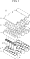
- FIG. 1 shows an exploded perspective view of a rechargeable battery module according to a first embodiment of the present disclosure
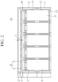
- FIG. 2 shows a cross-sectional view with respect to a line II-II of FIG. 1
- the rechargeable battery module 100 includes a plurality of battery cells 30, a first holder 11, a second holder 12, a first plate 21, and a second plate 22.
- the battery cells 30 may be formed to be cylindrical rechargeable batteries with a vent hole 31.
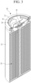
- FIG. 3 shows a cross-sectional perspective view of a cylindrical battery cell applied to FIG. 1 .
- the cylindrical battery cell 30 includes an electrode assembly 32 for performing a charging and discharging, a case 33 housing the electrode assembly 32, and a cap assembly 34 electrically connected to the electrode assembly 32 and combined to an opening of the case 33 in an insulated state.
- the cap plate 35 forming the cap assembly 34 may include a vent hole 31 and may discharge an emission through the vent hole 31 when the vent 36 is incised.
- the emission includes vent gas, explosion pressures, flame, and debris.
- the first holder 11 forms a plurality of first receivers 111 to receive a first-side lower portion of the battery cells 30 and support the same.
- the second holder 12 forms a plurality of second receivers 121 to receive a second-side upper portion of the battery cells 30 and support the same.
- the second holder 12 is combined to the first holder 11 to receive the battery cells 30 in the first and second receivers 111 and 121.
- the first holder 11 includes a first protrusion 113 to support a first-side lower portion of the battery cell 30, and the second holder 12 includes a second protrusion 123 to support a second-side upper portion of the battery cell 30.
- the first and second protrusions 113 and 123 prevent the battery cell 30 from leaving upward or downward in the first and second holders 11 and 12 in the drawing.
- the first plate 21 is provided on a first-side upper portion of the second holder 12 and respectively include an outlet group 40 formed of a plurality of outlets 41 on positions corresponding to the respective vent holes 31 of the battery cells 30.
- the first plate 21 may be formed by plastic injection molding.
- the second plate 22 is disposed on a first-side upper portion of the first plate 21 and is connected to the vent hole 31 and the outlets 41 of the outlet group 40 to block the emission discharged through the vent hole 31. That is, the second plate 22 intercepts the vent gas, explosion pressures, flame, and debris discharged through the vent hole 31.
- the first and second plates 21 and 22 form a gap G in an up and down direction.
- a space between the first and second plates 21 and 22 caused by the gap G buffers the explosion pressure, radiates the flame, and block the debris to prevent the same from being scattered to the outside of the rechargeable battery module 100.
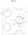
- FIG. 4 shows a partial top plan view of a first plate applied to FIG. 1
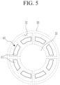
- FIG. 5 shows a top plan view of an outlet relationship of a first plate on a vent hole of a battery cell shown in FIG. 1 and FIG. 2 .
- the outlet 41 has a first width W1 in a diameter direction and has a first length L1 in a circumferential direction.
- the first length L1 represents a length of a curve established in a middle of the first width W1.
- the outlet group 40 includes a plurality of outlets 41 and has a first gap G1 in the circumferential direction.
- the first gap G1 represents a length of a curve established between the two neighboring outlets 41 in the middle of the first width W1.
- the outlets 41 are formed in the outlet group 40, and the adjacent outlets 41 may be set to have an angle ( ⁇ ) of 15° to 60° with respect to the first length L1.
- the adjacent outlets 41 may be set to have an angle ( ⁇ ) of 15° to 60° with respect to the first length L1.
- eight outlets 41 are formed in the outlet group 40, and two adjacent outlets 41 are set to have an angle ( ⁇ ) of 45° with respect to the first length L1.
- Performance for intercepting the discharged explosion pressures, flame, and debris is determined by the number of the outlets 41. When the number of the outlets 41 is established, the performance for intercepting the discharged explosion pressures, flame, and debris is determined by the sizes of the first width W1, the first length L1, and the first gap G1 of the outlet 41.
- the outlet group 40 forms an entire area (A1-A2) by an external first diameter D1 and an internal second diameter D2. That is, the first diameter D1 forms the first area A1, and the second diameter D2 forms the second area A2. Therefore, the entire area (A1-A2) of the outlet group 40 is calculated by subtracting the second area A2 from the first area A1.
- the entire area (A1-A2) of the outlet group 40 includes an opened area (A3*N) by a plurality of outlets 41 and a closed area (A4*N) by a space among the outlets 41.
- the opened area (A3*N) is set to be A3*8, and the closed area (A4*N) is set to be A4*8.
- An area ratio ((A4*N)/(A1-A2)) of the closed area (A4*N) for the entire area (A1-A2) of the outlet group 40 is established to be greater than 10.78% and less than 31.3%.
- the area ratio ((A4*N)/(A1-A2)) is equal to or less than 10.78%, molding becomes difficult during injection.
- the area ratio ((A4*N)/(A1-A2)) is greater than 10.78% and equal to or less than 15.4%, the injection molding is possible, and the outlets 41 are normally operated by the explosion pressure, flame, and debris discharged by the vent hole 31 of the corresponding battery cell 30. Therefore, the entire area (A1-A2) of the outlet group 40 established by the outlets 41 is removed, and the outlet groups 40 are maintained to be in a normal state on the first plate 21 on which the normal battery cells 30 that are not exploded are disposed. By this, the outlets 41 are smoothly opened in in an emergency, and the chain explosion of the peripheral battery cells 30 may be prevented.
- the area ratio ((A4*N)/(A1-A2)) of the closed area (A4*N) to the entire area (A1-A2) of the outlet group 40 may be established to be greater than 15.4% and less than 31.3%.
- the outlets 41 are normally operated by the explosion pressure, flame, and debris discharged from the vent hole 31 of the corresponding battery cell 30.
- the entire area (A1-A2) of the outlet group 40 established by the outlets 41 is removed, and the outlet groups 40 may be maintained to be in the normal state on the first plate 21 on which the normal battery cells 30 that are not exploded are disposed. Hence, the outlets 41 are smoothly opened in in an emergency, thereby preventing the chain explosion of the peripheral battery cells 30.
- the entire area (A1-A2) of the outlet group 40 may not be normally operated and the first plate 21 may be removed by the discharged explosion pressure, flame, and debris.
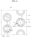
- FIG. 6 shows a top plan view of a first plate applied to a rechargeable battery module according to a second embodiment of the present disclosure
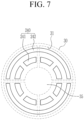
- FIG. 7 shows a top plan view of an outlet relationship of a first plate on a vent hole of a battery cell in FIG. 6 .
- the first plate 221 is installed on the first-side upper portion of the second holder 12 and includes an outlet group 240 including a plurality of first outlets 241 and second outlets 242 on the position that corresponds to the respective vent holes 31 of the battery cells 30.
- the outlet group 240 includes a plurality of first outlets 241 corresponding to the vent hole 31 and a plurality of second outlets 242 installed on the exterior circumference of the first outlets 241.
- the first outlets 241 may be installed inside the diameter direction
- the second outlets 242 may be installed outside the diameter direction.
- the first outlet 241 has the first width W1 in the diameter direction and has the first length L1 in the circumferential direction.
- the first length L1 represents the length of a curve established in the middle of the first width W1.
- the first outlets 241 have a first gap G1 in the circumferential direction.
- the first gap G1 represents the length of a curve established between the two neighboring first outlets 241 in the middle of the first width W1.
- first outlets 241 are formed, and the two adjacent first outlets 241 are established to have the angle of 45° ( ⁇ ) with respect to the first length L1. They control performance for intercepting some of the explosion pressure, flame, and debris according to the number of the first outlets 241. When the number of the first outlets 241 is established, they control the performance for intercepting some of the explosion pressure, flame, and debris discharged according to the sizes of the first width W1, the first length L1, and the first gap G1 of the first outlet 241.
- the second outlets 242 have a second width W2 in the diameter direction and have a second length L2 in the circumferential direction.
- the second length L2 represents the length of a curve established in the middle of the second width W2.
- the second outlets 242 have a second gap G2 in the circumferential direction.
- the second gap G2 represents the length of a curve established between the two neighboring second outlets 242 in the middle of the second width W2.
- the multiple second outlets 242 are formed, and the adjacent second outlets 242 may be established to have the angle ( ⁇ 2) of 90° to 180° with respect to the second length L2.
- two second outlets 242 are formed, and the two adjacent second outlets 242 are established to have the angle ( ⁇ 2) of 180° with respect to the second length L2. They control performance for intercepting the remaining portion of the explosion pressure, flame, and debris discharged according to the number of the second outlets 242.
- the number of the second outlets 242 When the number of the second outlets 242 is established, they control the performance for intercepting the remaining portion of the explosion pressure, flame, and debris discharged according to the sizes of the second width W2, the second length L2, and the second gap G2.
- the first outlets 241 form the first entire area (A1-A2) by the external first diameter D1 and the internal second diameter D2. That is, the first diameter D1 forms a first area A1, and the second diameter D2 forms a second area A2. Therefore, the entire area (A1-A2) in the area of the first outlets 241 of the outlet group 240 is calculated by subtracting the second area A2 from the first area A1.
- the first entire area (A1-A2) includes an opened area (A3*N) caused by a plurality of first outlets 241 and a first closed area (A4*N) by a space among a plurality of first outlets 241 in the region of the first outlets 241 according to a second embodiment.
- the second outlets 242 form the second entire area (A21-A22) by the external second 1-diameter D21 and the internal second 2-diameter D22. That is, the second 1-diameter D21 forms the first area A21, and the second 2-diameter D22 forms the second area A22. Hence, the entire area (A21-A22) is calculated by subtracting the second area A22 from the first area A21 in the region of the second outlets 242 of the outlet group 240.
- the second entire area (A21-A22) includes an opened area (A23*N) by a plurality of second 1-outlets 241 and a second closed area (A24*N) by a space among a plurality of second outlets 242.
- an area ratio of the sum of the first closed area (A4*N) and the second closed area (A24*N) to the sum of the first entire area (A1-A2) and the second entire area (A21-A22), that is, the area ratio (((A4*N)+(A24*N))/((A1-A2)+(A21-A22))) of the closed area ((A4*N)+(A24*N)) to the entire area ((A1-A2)+(A21-A22)) may be established to be greater than about 10.78% and less than about 31.3%.
- the first and second entire areas (A1-A2 and A21-A22) of the outlet group 240 established with the first outlets 241 and the second outlets 242 are removed, and the outlet groups 240 are maintained to be in the normal state on the first plate 21 on which the normal battery cells 30 that are not exploded are disposed. Hence, as the first outlets 241 and the second outlets 242 are smoothly opened in an emergency, the chain explosion of the peripheral battery cells 30 may be prevented.
- the area ratio (((A4*N)+(A24*N))/((A1-A2)+(A21-A22))) of the outlet group 240 may be established to be greater than 15.4% and less than 31.3%.
- the area ratio (((A4*N)+(A24*N))/((A1-A2)+(A21-A22))) is greater than 15.4% and less than 31.3%, the first outlets 241 and the second outlets 242 are normally operated by the explosion pressure, flame, and debris discharged by the vent hole 31 of the corresponding battery cell 30.
- the first and second entire areas (A1-A2 and A21-A22) of the outlet group 240 established with the first outlets 241 and the second outlets 242 are removed, and the outlet groups 240 may be maintained at the normal state on the first plate 21 on which the normal battery cells 30 that are not exploded are disposed. Hence, the first outlets 241 and the second outlets 242 are smoothly opened in an emergency, thereby preventing the chain explosion of the peripheral battery cells 30.
- the area ratio (((A4*N)+(A24*N))/((A1-A2)+(A21-A22))) of the outlet group 240 is equal to or greater than 31.3%
- the first and second entire areas (A1-A2 and A21-A22) of the first outlets 241 and the second outlets 242 may not be normally operated and the first plate 21 may be entirely removed by the discharged explosion pressure, flame, and debris.
- first holder 12 second holder 21, 221: first plate 22: second plate 30: battery cell 31: vent hole 32: electrode assembly 33: case 34: cap assembly 35: cap plate 36: vent 40, 240: outlet group 41: outlet 100, 200: rechargeable battery module 111: first receiver 113: first protrusion 121: second receiver 123: second protrusion 241: first outlet 242: second outlet A1: first area A2: second area A1-A2: first entire area A3: opened area A4: closed area A21: first area A22: second area A21-A22: second entire area A23: second opened area A24: second closed area D1: first diameter D2: second diameter D21: second-1 diameter D22: second-2 diameter G: gap G1: first gap G2: second gap L1: first length L2: second length W1: first width W2: second width ⁇ , ⁇ 2: angle
Landscapes
- Chemical & Material Sciences (AREA)
- Chemical Kinetics & Catalysis (AREA)
- Electrochemistry (AREA)
- General Chemical & Material Sciences (AREA)
- Gas Exhaust Devices For Batteries (AREA)
- Battery Mounting, Suspending (AREA)
Abstract
An embodiment of the present disclosure provides a rechargeable battery module for smoothly opening the vent in an emergency and preventing a chain explosion of peripheral battery cells. The rechargeable battery module includes: a plurality of battery cells including a vent hole; a first holder for receiving one of sides of the battery cells and supporting the same; a second holder receiving other sides of the battery cells and supporting the same and combined to the first holder; a first plate installed on one side of the second holder and installing an outlet group made of a plurality of outlets on positions corresponding to the respective vent holes of the battery cells; and a second plate disposed on one side of the first plate, and intercepting an emission discharged through the vent hole and the outlet group.
Description
- The present disclosure relates to a rechargeable battery module. More particularly, the present disclosure relates to a rechargeable battery module for preventing chain explosion of peripheral battery cells by providing smooth vent opening in an emergency.
- A rechargeable battery repeats charging and discharging, differing from a primary cell. A small rechargeable battery is used for portable small electronic devices such as a mobile phone, a laptop computer, or a camcorder. A large capacity and high density rechargeable battery is used to store motor driving power or energy of hybrid vehicles and electric vehicles.
- The rechargeable battery includes an electrode assembly for charging and discharging a current, a case for receiving the electrode assembly and an electrolyte solution, and an electrode terminal connected to the electrode assembly and drawn to an outside of the case. The electrode assembly may be made in a jellyroll type formed by winding an electrode and a separation film.
- An electric vehicle and an energy storage device need a large capacity of rechargeable battery modules. The large capacity of rechargeable battery modules includes a plurality of battery cells. When a fire or an explosion happens to a battery cell of the module, flame or gas at a high temperature discharged by the battery cell may be transmitted to neighboring battery cells to cause a chain explosion.
- Hence, methods for preventing the drawbacks are needed. For example, there is a potting method for covering a positive electrode of the battery cell with a foamed urethane or a silicon material. A potting material protects the battery cell from air and moisture in the ordinary days, foamed pores are generated in an emergency such as a thermal runaway to fluently discharge vent gas and debris of the battery cell, and the potting material prevents the discharged debris from being transmitted to the adjacent battery cells to thus prevent a chain explosion.
- The potting material is expensive and is difficult in managing its process so it increases total processing costs of the rechargeable battery module, and the potting material permeates into a space between a cap assembly in a cylindrical battery to stop vent opening of the battery cell and resultantly generate side effects such as a side rupture.
- The above information disclosed in this Background section is only for enhancement of understanding of the background of the disclosure, and therefore it may contain information that does not form the prior art that is already known in this country to a person of ordinary skill in the art.
- The present disclosure has been made in an effort to provide a rechargeable battery module for preventing a chain explosion of peripheral battery cells by providing a smooth vent opening in an emergency.
- An embodiment of the present disclosure provides a rechargeable battery module including: a plurality of battery cells including a vent hole; a first holder for receiving one of sides of the battery cells and supporting the same; a second holder receiving other sides of the battery cells and supporting the same and combined to the first holder; a first plate installed on one side of the second holder and installing (e.g. including) an outlet group made of a plurality of outlets at positions corresponding to the respective vent holes of the battery cells; and a second plate disposed on one side of the first plate, and intercepting (e.g. configured to intercept) an emission discharged through the vent hole and the outlet group.
- The battery cells may be made into (e.g. may be in the form of) a cylindrical rechargeable battery.
- The outlet may have a first width in a diameter direction and may have a first length in a circumferential direction, and the outlet group may include the outlets and may have a first gap in the circumferential direction.
- The outlet group may generate an entire area (A1-A2) by an external first diameter D1 and an internal second diameter D2, the entire area (A1-A2) may include an opened area (A3*N) caused by a plurality of first outlets and a closed area (A4*N) caused by a space among a plurality of first outlets, and a ratio of the closed area (A4*N) to the entire area (A1-A2) may be established to be greater than 10.78% and less than 31.3%.
- The ratio (A4*N) of the closed area to the entire area (A1-A2) may be established to be greater than 10.78% and equal to or less than 15.4%.
- The ratio (A4*N) of the closed area to the entire area (A1-A2) may be established to be greater than 15.4% and less than 31.3%.
- The outlet group may include a plurality of first outlets corresponding to the vent hole and a plurality of second outlets installed on an exterior circumference of the first outlets.
- The first outlet may have a first width in the diameter direction and may have a first length in the circumferential direction, the first outlets may have a first gap in the circumferential direction, the second outlets may have a second width in the diameter direction and may have a second length in the circumferential direction, and the second outlets may have a second gap in the circumferential direction.
- The first outlets may generate a first entire area (A1-A2) by an external first diameter D1 and an internal second diameter D2, the first entire area (A1-A2) may include an opened area (A3*N) caused by a plurality of first outlets and a first closed area (A4*N) caused by a space among a plurality of first outlets, the second outlets may generate a second entire area (A21-A22) by an external second 1-diameter D21 and an internal second 2-diameter D22, the second entire area (A21-A22) may include an opened area (A23*N) caused by a plurality of second-1 outlets and a second closed area (A24*N) caused by a plurality of second outlets, and a ratio of a sum of the first closed area (A4*N) and the second closed area (A24*N) to a sum of the first entire area (A1-A2) and second entire area (A21-A22) may be established to be greater than 10.78% and less than 31.3.
- The ratio of a sum of the first closed area (A4*N) and the second closed area (A24*N) to a sum of the first entire area (A1-A2) and the second entire area (A21-A22) may be further established to be greater than 10.78% and equal to or less than 15.4%.
- The ratio of a sum of the first closed area (A4*N) and the second closed area (A24*N) to a sum of the first entire area (A1-A2) and the second entire area (A21-A22) may be further established to be greater than 15.4% and less than 31.3%.
- At least some of the above and other features of the invention are set out in the claims.
- According to the embodiment of the present disclosure, the outlet group is formed in the first plate to correspond the respective outlets to the vent holes of the respective battery cells, smoothly open the outlets in an emergency, and discharge explosion pressures, flame, and debris to the outside of the first plate, thereby preventing the chain explosion of the peripheral battery cells inside the first plate.
-
-
FIG. 1 shows an exploded perspective view of a rechargeable battery module according to a first embodiment of the present disclosure. -
FIG. 2 shows a cross-sectional view with respect to a line II-II ofFIG. 1 . -
FIG. 3 shows a cross-sectional perspective view of a cylindrical battery cell applied toFIG. 1 . -
FIG. 4 shows a partial top plan view of a first plate applied toFIG. 1 . -
FIG. 5 shows a top plan view of an outlet relationship of a first plate on a vent hole of a battery cell shown inFIG. 1 andFIG. 2 . -
FIG. 6 shows a top plan view of a first plate applied to a rechargeable battery module according to a second embodiment of the present disclosure. -
FIG. 7 shows a top plan view of an outlet relationship of a first plate on a vent hole of a battery cell inFIG. 6 . - The present disclosure will be described more fully hereinafter with reference to the accompanying drawings, in which embodiments of the disclosure are shown. As those skilled in the art would realize, the described embodiments may be modified in various different ways, all without departing from the scope of the present disclosure. The drawings and description are to be regarded as illustrative in nature and not restrictive. Like reference numerals designate like elements throughout the specification.
-
FIG. 1 shows an exploded perspective view of a rechargeable battery module according to a first embodiment of the present disclosure, andFIG. 2 shows a cross-sectional view with respect to a line II-II ofFIG. 1 . Referring toFIG. 1 andFIG. 2 , therechargeable battery module 100 includes a plurality ofbattery cells 30, afirst holder 11, asecond holder 12, afirst plate 21, and asecond plate 22. As an embodiment, thebattery cells 30 may be formed to be cylindrical rechargeable batteries with avent hole 31. -
FIG. 3 shows a cross-sectional perspective view of a cylindrical battery cell applied toFIG. 1 . Referring toFIG. 3 , thecylindrical battery cell 30 includes anelectrode assembly 32 for performing a charging and discharging, acase 33 housing theelectrode assembly 32, and acap assembly 34 electrically connected to theelectrode assembly 32 and combined to an opening of thecase 33 in an insulated state. Thecap plate 35 forming thecap assembly 34 may include avent hole 31 and may discharge an emission through thevent hole 31 when thevent 36 is incised. The emission includes vent gas, explosion pressures, flame, and debris. - Referring to
FIG. 1 andFIG. 2 , thefirst holder 11 forms a plurality offirst receivers 111 to receive a first-side lower portion of thebattery cells 30 and support the same. Thesecond holder 12 forms a plurality ofsecond receivers 121 to receive a second-side upper portion of thebattery cells 30 and support the same. Thesecond holder 12 is combined to thefirst holder 11 to receive thebattery cells 30 in the first andsecond receivers - For example, the
first holder 11 includes afirst protrusion 113 to support a first-side lower portion of thebattery cell 30, and thesecond holder 12 includes asecond protrusion 123 to support a second-side upper portion of thebattery cell 30. The first andsecond protrusions battery cell 30 from leaving upward or downward in the first andsecond holders - The
first plate 21 is provided on a first-side upper portion of thesecond holder 12 and respectively include anoutlet group 40 formed of a plurality ofoutlets 41 on positions corresponding to therespective vent holes 31 of thebattery cells 30. For example, thefirst plate 21 may be formed by plastic injection molding. - The
second plate 22 is disposed on a first-side upper portion of thefirst plate 21 and is connected to thevent hole 31 and theoutlets 41 of theoutlet group 40 to block the emission discharged through thevent hole 31. That is, thesecond plate 22 intercepts the vent gas, explosion pressures, flame, and debris discharged through thevent hole 31. - For this purpose, the first and
second plates second plates rechargeable battery module 100. -
FIG. 4 shows a partial top plan view of a first plate applied toFIG. 1 , andFIG. 5 shows a top plan view of an outlet relationship of a first plate on a vent hole of a battery cell shown inFIG. 1 andFIG. 2 . - Referring to
FIG. 1 to FIG. 5 , regarding theoutlet group 40 of thefirst plate 21, theoutlet 41 has a first width W1 in a diameter direction and has a first length L1 in a circumferential direction. The first length L1 represents a length of a curve established in a middle of the first width W1. Theoutlet group 40 includes a plurality ofoutlets 41 and has a first gap G1 in the circumferential direction. The first gap G1 represents a length of a curve established between the two neighboringoutlets 41 in the middle of the first width W1. - The
outlets 41 are formed in theoutlet group 40, and theadjacent outlets 41 may be set to have an angle (θ) of 15° to 60° with respect to the first length L1. For example, eightoutlets 41 are formed in theoutlet group 40, and twoadjacent outlets 41 are set to have an angle (θ) of 45° with respect to the first length L1. Performance for intercepting the discharged explosion pressures, flame, and debris is determined by the number of theoutlets 41. When the number of theoutlets 41 is established, the performance for intercepting the discharged explosion pressures, flame, and debris is determined by the sizes of the first width W1, the first length L1, and the first gap G1 of theoutlet 41. - The
outlet group 40 forms an entire area (A1-A2) by an external first diameter D1 and an internal second diameter D2. That is, the first diameter D1 forms the first area A1, and the second diameter D2 forms the second area A2. Therefore, the entire area (A1-A2) of theoutlet group 40 is calculated by subtracting the second area A2 from the first area A1. - In a first embodiment, the entire area (A1-A2) of the
outlet group 40 includes an opened area (A3*N) by a plurality ofoutlets 41 and a closed area (A4*N) by a space among theoutlets 41. The opened area (A3*N) is set to be A3*8, and the closed area (A4*N) is set to be A4*8. An area ratio ((A4*N)/(A1-A2)) of the closed area (A4*N) for the entire area (A1-A2) of theoutlet group 40 is established to be greater than 10.78% and less than 31.3%. - When the area ratio ((A4*N)/(A1-A2)) is equal to or less than 10.78%, molding becomes difficult during injection. When the area ratio ((A4*N)/(A1-A2)) is greater than 10.78% and equal to or less than 15.4%, the injection molding is possible, and the
outlets 41 are normally operated by the explosion pressure, flame, and debris discharged by thevent hole 31 of thecorresponding battery cell 30. Therefore, the entire area (A1-A2) of theoutlet group 40 established by theoutlets 41 is removed, and theoutlet groups 40 are maintained to be in a normal state on thefirst plate 21 on which thenormal battery cells 30 that are not exploded are disposed. By this, theoutlets 41 are smoothly opened in in an emergency, and the chain explosion of theperipheral battery cells 30 may be prevented. - The area ratio ((A4*N)/(A1-A2)) of the closed area (A4*N) to the entire area (A1-A2) of the
outlet group 40 may be established to be greater than 15.4% and less than 31.3%. When the area ratio ((A4*N)/(A1-A2)) is greater than 15.4% and less than 31.3%, theoutlets 41 are normally operated by the explosion pressure, flame, and debris discharged from thevent hole 31 of thecorresponding battery cell 30. The entire area (A1-A2) of theoutlet group 40 established by theoutlets 41 is removed, and theoutlet groups 40 may be maintained to be in the normal state on thefirst plate 21 on which thenormal battery cells 30 that are not exploded are disposed. Hence, theoutlets 41 are smoothly opened in in an emergency, thereby preventing the chain explosion of theperipheral battery cells 30. - However, when the area ratio ((A4*N)/(A1-A2)) of the closed area (A4*N) to the entire area (A1-A2) of the
outlet group 40 is equal to or greater than 31.3%, the entire area (A1-A2) of theoutlet group 40 may not be normally operated and thefirst plate 21 may be removed by the discharged explosion pressure, flame, and debris. - A second embodiment of the present disclosure will now be described. The second embodiment will be compared with the first embodiment, same portions will not be described, and different portions will be described.
-
FIG. 6 shows a top plan view of a first plate applied to a rechargeable battery module according to a second embodiment of the present disclosure, andFIG. 7 shows a top plan view of an outlet relationship of a first plate on a vent hole of a battery cell inFIG. 6 . - Referring to
FIG. 6 andFIG. 7 , regarding therechargeable battery module 200 according to a second embodiment, thefirst plate 221 is installed on the first-side upper portion of thesecond holder 12 and includes anoutlet group 240 including a plurality offirst outlets 241 andsecond outlets 242 on the position that corresponds to the respective vent holes 31 of thebattery cells 30. - That is, the
outlet group 240 includes a plurality offirst outlets 241 corresponding to thevent hole 31 and a plurality ofsecond outlets 242 installed on the exterior circumference of thefirst outlets 241. For example, thefirst outlets 241 may be installed inside the diameter direction, and thesecond outlets 242 may be installed outside the diameter direction. - The
first outlet 241 has the first width W1 in the diameter direction and has the first length L1 in the circumferential direction. The first length L1 represents the length of a curve established in the middle of the first width W1. Thefirst outlets 241 have a first gap G1 in the circumferential direction. The first gap G1 represents the length of a curve established between the two neighboringfirst outlets 241 in the middle of the first width W1. - For example, eight
first outlets 241 are formed, and the two adjacentfirst outlets 241 are established to have the angle of 45° (θ) with respect to the first length L1. They control performance for intercepting some of the explosion pressure, flame, and debris according to the number of thefirst outlets 241. When the number of thefirst outlets 241 is established, they control the performance for intercepting some of the explosion pressure, flame, and debris discharged according to the sizes of the first width W1, the first length L1, and the first gap G1 of thefirst outlet 241. - The
second outlets 242 have a second width W2 in the diameter direction and have a second length L2 in the circumferential direction. The second length L2 represents the length of a curve established in the middle of the second width W2. Thesecond outlets 242 have a second gap G2 in the circumferential direction. The second gap G2 represents the length of a curve established between the two neighboringsecond outlets 242 in the middle of the second width W2. - The multiple
second outlets 242 are formed, and the adjacentsecond outlets 242 may be established to have the angle (θ2) of 90° to 180° with respect to the second length L2. For example, twosecond outlets 242 are formed, and the two adjacentsecond outlets 242 are established to have the angle (θ2) of 180° with respect to the second length L2. They control performance for intercepting the remaining portion of the explosion pressure, flame, and debris discharged according to the number of thesecond outlets 242. When the number of thesecond outlets 242 is established, they control the performance for intercepting the remaining portion of the explosion pressure, flame, and debris discharged according to the sizes of the second width W2, the second length L2, and the second gap G2. - In a like way of the
outlet group 40 according to a first embodiment, thefirst outlets 241 form the first entire area (A1-A2) by the external first diameter D1 and the internal second diameter D2. That is, the first diameter D1 forms a first area A1, and the second diameter D2 forms a second area A2. Therefore, the entire area (A1-A2) in the area of thefirst outlets 241 of theoutlet group 240 is calculated by subtracting the second area A2 from the first area A1. - The first entire area (A1-A2) includes an opened area (A3*N) caused by a plurality of
first outlets 241 and a first closed area (A4*N) by a space among a plurality offirst outlets 241 in the region of thefirst outlets 241 according to a second embodiment. - The
second outlets 242 form the second entire area (A21-A22) by the external second 1-diameter D21 and the internal second 2-diameter D22. That is, the second 1-diameter D21 forms the first area A21, and the second 2-diameter D22 forms the second area A22. Hence, the entire area (A21-A22) is calculated by subtracting the second area A22 from the first area A21 in the region of thesecond outlets 242 of theoutlet group 240. - In the region of the
second outlets 242, the second entire area (A21-A22) includes an opened area (A23*N) by a plurality of second 1-outlets 241 and a second closed area (A24*N) by a space among a plurality ofsecond outlets 242. - In the
outlet group 240, an area ratio of the sum of the first closed area (A4*N) and the second closed area (A24*N) to the sum of the first entire area (A1-A2) and the second entire area (A21-A22), that is, the area ratio (((A4*N)+(A24*N))/((A1-A2)+(A21-A22))) of the closed area ((A4*N)+(A24*N)) to the entire area ((A1-A2)+(A21-A22)) may be established to be greater than about 10.78% and less than about 31.3%. - When the area ratio (((A4*N)+(A24*N))/((A1-A2)+(A21-A22))) is equal to or less than 10.78%, molding becomes difficult during injection. When the area ratio (((A4*N)+(A24*N))/((A1-A2)+(A21-A22))) is greater than 10.78% and equal to or less than 15.4%, the injection molding is possible, and the
first outlets 241 and thesecond outlets 242 are normally operated by the explosion pressure, flame, and debris discharged by thevent hole 31 of thecorresponding battery cell 30. Therefore, the first and second entire areas (A1-A2 and A21-A22) of theoutlet group 240 established with thefirst outlets 241 and thesecond outlets 242 are removed, and theoutlet groups 240 are maintained to be in the normal state on thefirst plate 21 on which thenormal battery cells 30 that are not exploded are disposed. Hence, as thefirst outlets 241 and thesecond outlets 242 are smoothly opened in an emergency, the chain explosion of theperipheral battery cells 30 may be prevented. - The area ratio (((A4*N)+(A24*N))/((A1-A2)+(A21-A22))) of the
outlet group 240 may be established to be greater than 15.4% and less than 31.3%. When the area ratio (((A4*N)+(A24*N))/((A1-A2)+(A21-A22))) is greater than 15.4% and less than 31.3%, thefirst outlets 241 and thesecond outlets 242 are normally operated by the explosion pressure, flame, and debris discharged by thevent hole 31 of thecorresponding battery cell 30. Therefore, the first and second entire areas (A1-A2 and A21-A22) of theoutlet group 240 established with thefirst outlets 241 and thesecond outlets 242 are removed, and theoutlet groups 240 may be maintained at the normal state on thefirst plate 21 on which thenormal battery cells 30 that are not exploded are disposed. Hence, thefirst outlets 241 and thesecond outlets 242 are smoothly opened in an emergency, thereby preventing the chain explosion of theperipheral battery cells 30. - However, when the area ratio (((A4*N)+(A24*N))/((A1-A2)+(A21-A22))) of the
outlet group 240 is equal to or greater than 31.3%, the first and second entire areas (A1-A2 and A21-A22) of thefirst outlets 241 and thesecond outlets 242 may not be normally operated and thefirst plate 21 may be entirely removed by the discharged explosion pressure, flame, and debris. - While this disclosure has been described in connection with what is presently considered to be practical embodiments, it is to be understood that the disclosure is not limited to the disclosed embodiments, but, on the contrary, is intended to cover various modifications and equivalent arrangements included within the scope of the appended claims.
-
11: first holder 12: second holder 21, 221: first plate 22: second plate 30: battery cell 31: vent hole 32: electrode assembly 33: case 34: cap assembly 35: cap plate 36: vent 40, 240: outlet group 41: outlet 100, 200: rechargeable battery module 111: first receiver 113: first protrusion 121: second receiver 123: second protrusion 241: first outlet 242: second outlet A1: first area A2: second area A1-A2: first entire area A3: opened area A4: closed area A21: first area A22: second area A21-A22: second entire area A23: second opened area A24: second closed area D1: first diameter D2: second diameter D21: second-1 diameter D22: second-2 diameter G: gap G1: first gap G2: second gap L1: first length L2: second length W1: first width W2: second width θ, θ2: angle
Claims (11)
- A rechargeable battery module comprising:a plurality of battery cells including a vent hole;a first holder for receiving one of sides of the battery cells and supporting the same;a second holder receiving other sides of the battery cells and supporting the same and combined to the first holder;a first plate installed on one side of the second holder and including an outlet group made of a plurality of outlets at positions corresponding to the respective vent holes of the battery cells; anda second plate disposed on one side of the first plate, and configured to intercept an emission discharged through the vent hole and the outlet group.
- The rechargeable battery module of claim 1, wherein
the battery cells are in the form of a cylindrical rechargeable battery. - The rechargeable battery module of claim 1 or claim 2, whereinthe outlet has a first width in a diameter direction and has a first length in a circumferential direction, andthe outlet group includes the outlets and has a first gap in the circumferential direction.
- The rechargeable battery module of claim 3, whereinthe outlet group generates an entire area (A1-A2) by an external first diameter D1 and an internal second diameter D2,the entire area (A1-A2) includes an opened area (A3*N) caused by a plurality of first outlets and a closed area (A4*N) caused by a space among a plurality of first outlets, anda ratio of the closed area (A4*N) to the entire area (A1-A2) is established to be greater than 10.78% and less than 31.3%.
- The rechargeable battery module of claim 4, wherein
the ratio (A4*N) of the closed area to the entire area (A1-A2) is established to be greater than 10.78% and equal to or less than 15.4%. - The rechargeable battery module of claim 4, wherein
the ratio (A4*N) of the closed area to the entire area (A1-A2) is established to be greater than 15.4% and less than 31.3%. - The rechargeable battery module of claim 1, wherein
the outlet group includes a plurality of first outlets corresponding to the vent hole and a plurality of second outlets installed on an exterior circumference of the first outlets. - The rechargeable battery module of claim 7, whereinthe first outlet has a first width in the diameter direction and has a first length in the circumferential direction,the first outlets have a first gap in the circumferential direction,the second outlets have a second width in the diameter direction and have a second length in the circumferential direction, andthe second outlets have a second gap in the circumferential direction.
- The rechargeable battery module of claim 8, whereinthe first outlets generate a first entire area (A1-A2) by an external first diameter D1 and an internal second diameter D2,the first entire area (A1-A2) includes an opened area (A3*N) caused by a plurality of first outlets and a first closed area (A4*N) caused by a space among a plurality of first outlets,the second outlets generate a second entire area (A21-A22) by an external second 1-diameter D21 and an internal second 2-diameter D22,the second entire area (A21-A22) includes an opened area (A23*N) caused by a plurality of second-1 outlets and a second closed area (A24*N) caused by a plurality of second outlets, anda ratio of a sum of the first closed area (A4*N) and the second closed area (A24*N) to a sum of the first entire area (A1-A2) and second entire area (A21-A22) is established to be greater than 10.78% and less than 31.3%.
- The rechargeable battery module of claim 9, wherein
the ratio of a sum of the first closed area (A4*N) and the second closed area (A24*N) to a sum of the first entire area (A1-A2) and the second entire area (A21-A22) is further established to be greater than 10.78% and equal to or less than 15.4%. - The rechargeable battery module of claim 9, wherein
the ratio of a sum of the first closed area (A4*N) and the second closed area (A24*N) to a sum of the first entire area (A1-A2) and the second entire area (A21-A22) is further established to be greater than 15.4% and less than 31.3%.
Applications Claiming Priority (2)
| Application Number | Priority Date | Filing Date | Title |
|---|---|---|---|
| KR20220169818 | 2022-12-07 | ||
| KR1020230121977A KR102805378B1 (en) | 2022-12-07 | 2023-09-13 | Rechargeable battery module |
Publications (1)
| Publication Number | Publication Date |
|---|---|
| EP4383420A1 true EP4383420A1 (en) | 2024-06-12 |
Family
ID=88969483
Family Applications (1)
| Application Number | Title | Priority Date | Filing Date |
|---|---|---|---|
| EP23211960.2A Pending EP4383420A1 (en) | 2022-12-07 | 2023-11-24 | Rechargeable battery module |
Country Status (3)
| Country | Link |
|---|---|
| US (1) | US12548847B2 (en) |
| EP (1) | EP4383420A1 (en) |
| JP (1) | JP7739390B2 (en) |
Citations (3)
| Publication number | Priority date | Publication date | Assignee | Title |
|---|---|---|---|---|
| US9941496B2 (en) * | 2014-10-01 | 2018-04-10 | Toyota Jidosha Kabushiki Kaisha | On-board power source device |
| EP3828987A1 (en) * | 2019-11-29 | 2021-06-02 | Samsung SDI Co., Ltd. | Battery pack |
| WO2022031056A1 (en) * | 2020-08-04 | 2022-02-10 | 주식회사 엘지에너지솔루션 | Battery module, battery pack comprising same, and automobile |
Family Cites Families (18)
| Publication number | Priority date | Publication date | Assignee | Title |
|---|---|---|---|---|
| JP2003257389A (en) * | 2002-03-06 | 2003-09-12 | Sony Corp | Battery device |
| US20080085450A1 (en) | 2006-10-05 | 2008-04-10 | Depalma Christopher L | End cap seal assembly for an electrochemical cell |
| KR100966549B1 (en) | 2008-10-14 | 2010-06-29 | 주식회사 엘지화학 | Cap assembly with improved safety and cylindrical secondary battery containing same |
| JP4935802B2 (en) | 2008-12-10 | 2012-05-23 | パナソニック株式会社 | Battery module and assembled battery module using the same |
| WO2011007547A1 (en) | 2009-07-17 | 2011-01-20 | パナソニック株式会社 | Battery module and battery pack using same |
| US8597809B2 (en) | 2010-02-18 | 2013-12-03 | Samsung Sdi Co., Ltd. | Rechargeable battery |
| US10158102B2 (en) * | 2013-08-30 | 2018-12-18 | Gogoro Inc. | Portable electrical energy storage device with thermal runaway mitigation |
| JP6283964B2 (en) * | 2014-02-07 | 2018-02-28 | パナソニックIpマネジメント株式会社 | Battery module |
| KR102238556B1 (en) * | 2014-02-28 | 2021-04-08 | 삼성에스디아이 주식회사 | Rechargeable battery pack |
| JP6551177B2 (en) | 2015-11-11 | 2019-07-31 | トヨタ自動車株式会社 | Battery unit |
| KR102410972B1 (en) * | 2017-09-22 | 2022-06-20 | 삼성에스디아이 주식회사 | Battery pack |
| JP2021152987A (en) | 2018-06-20 | 2021-09-30 | 三洋電機株式会社 | Power supply device |
| KR102501080B1 (en) * | 2019-11-29 | 2023-02-17 | 삼성에스디아이 주식회사 | Battery pack |
| WO2022025186A1 (en) * | 2020-07-30 | 2022-02-03 | パナソニックIpマネジメント株式会社 | Power storage device and power storage module |
| KR102940555B1 (en) | 2020-08-21 | 2026-03-18 | 주식회사 엘지에너지솔루션 | Battery Module To Control Thermal Runaway Propagation And Battery Pack Including It |
| KR102915798B1 (en) | 2020-12-02 | 2026-01-21 | 에스케이이노베이션 주식회사 | Recovery method of lithium precursor from disposed cathode materials of lithum battery |
| KR102892927B1 (en) | 2021-02-22 | 2025-11-27 | 주식회사 엘지에너지솔루션 | Battery module and battery pack including the same |
| EP4411956A4 (en) | 2021-09-30 | 2025-01-15 | Panasonic Intellectual Property Management Co., Ltd. | ELECTRICAL ENERGY STORAGE MODULE |
-
2023
- 2023-10-16 US US18/487,928 patent/US12548847B2/en active Active
- 2023-11-24 EP EP23211960.2A patent/EP4383420A1/en active Pending
- 2023-12-05 JP JP2023205328A patent/JP7739390B2/en active Active
Patent Citations (3)
| Publication number | Priority date | Publication date | Assignee | Title |
|---|---|---|---|---|
| US9941496B2 (en) * | 2014-10-01 | 2018-04-10 | Toyota Jidosha Kabushiki Kaisha | On-board power source device |
| EP3828987A1 (en) * | 2019-11-29 | 2021-06-02 | Samsung SDI Co., Ltd. | Battery pack |
| WO2022031056A1 (en) * | 2020-08-04 | 2022-02-10 | 주식회사 엘지에너지솔루션 | Battery module, battery pack comprising same, and automobile |
Also Published As
| Publication number | Publication date |
|---|---|
| US20240195004A1 (en) | 2024-06-13 |
| US12548847B2 (en) | 2026-02-10 |
| JP7739390B2 (en) | 2025-09-16 |
| JP2024082262A (en) | 2024-06-19 |
Similar Documents
| Publication | Publication Date | Title |
|---|---|---|
| US11961956B2 (en) | Cylindrical secondary battery module and method for producing cylindrical secondary battery module | |
| KR100440934B1 (en) | Secondary battery | |
| EP3582284B1 (en) | Rechargeable battery and battery module | |
| US20180097215A1 (en) | Cylindrical Battery Cell Comprising Metal Can Having Groove | |
| US9246144B2 (en) | Battery pack and method for manufacturing the same | |
| US20260100475A1 (en) | Battery pack and device including the same | |
| US20240222781A1 (en) | Battery Module and Battery Pack Including the Same | |
| KR102234223B1 (en) | Secondary Battery with improved Stability having Heat Expandable Tape and Method thereof | |
| US12512548B2 (en) | Battery pack and device including the same | |
| US7771862B2 (en) | Cap assembly and a safety valve for a secondary battery | |
| KR102394496B1 (en) | The Safety Vent | |
| US7758995B2 (en) | Serial interface between unit cells | |
| EP4383420A1 (en) | Rechargeable battery module | |
| EP4468466A1 (en) | Battery module with reinforced safety | |
| KR102805378B1 (en) | Rechargeable battery module | |
| CN118156699A (en) | Rechargeable battery module | |
| EP4443623A1 (en) | Rechargeable battery module | |
| EP4567974A1 (en) | Battery module and manufacturing method thereof | |
| US20250183419A1 (en) | Battery cell and battery module including the same | |
| US20250105438A1 (en) | Rechargeable battery | |
| US20240322355A1 (en) | Battery pack | |
| US20260106304A1 (en) | Battery module | |
| EP4080645A1 (en) | Battery module, battery pack comprising same battery module, and vehicle comprising same battery pack | |
| KR20250165744A (en) | Battery module | |
| KR20250080397A (en) | Battery pack for vehicle |
Legal Events
| Date | Code | Title | Description |
|---|---|---|---|
| PUAI | Public reference made under article 153(3) epc to a published international application that has entered the european phase |
Free format text: ORIGINAL CODE: 0009012 |
|
| STAA | Information on the status of an ep patent application or granted ep patent |
Free format text: STATUS: REQUEST FOR EXAMINATION WAS MADE |
|
| 17P | Request for examination filed |
Effective date: 20231124 |
|
| AK | Designated contracting states |
Kind code of ref document: A1 Designated state(s): AL AT BE BG CH CY CZ DE DK EE ES FI FR GB GR HR HU IE IS IT LI LT LU LV MC ME MK MT NL NO PL PT RO RS SE SI SK SM TR |