EP4383417A2 - Battery pack - Google Patents
Battery pack Download PDFInfo
- Publication number
- EP4383417A2 EP4383417A2 EP23213616.8A EP23213616A EP4383417A2 EP 4383417 A2 EP4383417 A2 EP 4383417A2 EP 23213616 A EP23213616 A EP 23213616A EP 4383417 A2 EP4383417 A2 EP 4383417A2
- Authority
- EP
- European Patent Office
- Prior art keywords
- terminal
- cell
- battery pack
- wall
- fuse
- Prior art date
- Legal status (The legal status is an assumption and is not a legal conclusion. Google has not performed a legal analysis and makes no representation as to the accuracy of the status listed.)
- Pending
Links
- RYGMFSIKBFXOCR-UHFFFAOYSA-N Copper Chemical compound [Cu] RYGMFSIKBFXOCR-UHFFFAOYSA-N 0.000 claims description 8
- XAGFODPZIPBFFR-UHFFFAOYSA-N aluminium Chemical compound [Al] XAGFODPZIPBFFR-UHFFFAOYSA-N 0.000 claims description 8
- 229910052782 aluminium Inorganic materials 0.000 claims description 8
- 229910052802 copper Inorganic materials 0.000 claims description 8
- 239000010949 copper Substances 0.000 claims description 8
- 230000008878 coupling Effects 0.000 claims description 8
- 238000010168 coupling process Methods 0.000 claims description 8
- 238000005859 coupling reaction Methods 0.000 claims description 8
- 239000011800 void material Substances 0.000 description 6
- WHXSMMKQMYFTQS-UHFFFAOYSA-N Lithium Chemical compound [Li] WHXSMMKQMYFTQS-UHFFFAOYSA-N 0.000 description 2
- PXHVJJICTQNCMI-UHFFFAOYSA-N Nickel Chemical compound [Ni] PXHVJJICTQNCMI-UHFFFAOYSA-N 0.000 description 2
- 229910052744 lithium Inorganic materials 0.000 description 2
- 230000007246 mechanism Effects 0.000 description 2
- 238000013021 overheating Methods 0.000 description 2
- 238000003466 welding Methods 0.000 description 2
- 238000004891 communication Methods 0.000 description 1
- 238000010276 construction Methods 0.000 description 1
- 230000000994 depressogenic effect Effects 0.000 description 1
- 238000002955 isolation Methods 0.000 description 1
- 238000012986 modification Methods 0.000 description 1
- 230000004048 modification Effects 0.000 description 1
- 229910052759 nickel Inorganic materials 0.000 description 1
Images



Classifications
-
- H—ELECTRICITY
- H01—ELECTRIC ELEMENTS
- H01M—PROCESSES OR MEANS, e.g. BATTERIES, FOR THE DIRECT CONVERSION OF CHEMICAL ENERGY INTO ELECTRICAL ENERGY
- H01M50/00—Constructional details or processes of manufacture of the non-active parts of electrochemical cells other than fuel cells, e.g. hybrid cells
- H01M50/20—Mountings; Secondary casings or frames; Racks, modules or packs; Suspension devices; Shock absorbers; Transport or carrying devices; Holders
- H01M50/284—Mountings; Secondary casings or frames; Racks, modules or packs; Suspension devices; Shock absorbers; Transport or carrying devices; Holders with incorporated circuit boards, e.g. printed circuit boards [PCB]
-
- H—ELECTRICITY
- H01—ELECTRIC ELEMENTS
- H01M—PROCESSES OR MEANS, e.g. BATTERIES, FOR THE DIRECT CONVERSION OF CHEMICAL ENERGY INTO ELECTRICAL ENERGY
- H01M10/00—Secondary cells; Manufacture thereof
- H01M10/42—Methods or arrangements for servicing or maintenance of secondary cells or secondary half-cells
- H01M10/425—Structural combination with electronic components, e.g. electronic circuits integrated to the outside of the casing
-
- H—ELECTRICITY
- H01—ELECTRIC ELEMENTS
- H01M—PROCESSES OR MEANS, e.g. BATTERIES, FOR THE DIRECT CONVERSION OF CHEMICAL ENERGY INTO ELECTRICAL ENERGY
- H01M50/00—Constructional details or processes of manufacture of the non-active parts of electrochemical cells other than fuel cells, e.g. hybrid cells
- H01M50/20—Mountings; Secondary casings or frames; Racks, modules or packs; Suspension devices; Shock absorbers; Transport or carrying devices; Holders
- H01M50/204—Racks, modules or packs for multiple batteries or multiple cells
- H01M50/207—Racks, modules or packs for multiple batteries or multiple cells characterised by their shape
-
- H—ELECTRICITY
- H01—ELECTRIC ELEMENTS
- H01M—PROCESSES OR MEANS, e.g. BATTERIES, FOR THE DIRECT CONVERSION OF CHEMICAL ENERGY INTO ELECTRICAL ENERGY
- H01M50/00—Constructional details or processes of manufacture of the non-active parts of electrochemical cells other than fuel cells, e.g. hybrid cells
- H01M50/20—Mountings; Secondary casings or frames; Racks, modules or packs; Suspension devices; Shock absorbers; Transport or carrying devices; Holders
- H01M50/247—Mountings; Secondary casings or frames; Racks, modules or packs; Suspension devices; Shock absorbers; Transport or carrying devices; Holders specially adapted for portable devices, e.g. mobile phones, computers, hand tools or pacemakers
-
- H—ELECTRICITY
- H01—ELECTRIC ELEMENTS
- H01M—PROCESSES OR MEANS, e.g. BATTERIES, FOR THE DIRECT CONVERSION OF CHEMICAL ENERGY INTO ELECTRICAL ENERGY
- H01M50/00—Constructional details or processes of manufacture of the non-active parts of electrochemical cells other than fuel cells, e.g. hybrid cells
- H01M50/50—Current conducting connections for cells or batteries
- H01M50/502—Interconnectors for connecting terminals of adjacent batteries; Interconnectors for connecting cells outside a battery casing
-
- H—ELECTRICITY
- H01—ELECTRIC ELEMENTS
- H01M—PROCESSES OR MEANS, e.g. BATTERIES, FOR THE DIRECT CONVERSION OF CHEMICAL ENERGY INTO ELECTRICAL ENERGY
- H01M50/00—Constructional details or processes of manufacture of the non-active parts of electrochemical cells other than fuel cells, e.g. hybrid cells
- H01M50/50—Current conducting connections for cells or batteries
- H01M50/502—Interconnectors for connecting terminals of adjacent batteries; Interconnectors for connecting cells outside a battery casing
- H01M50/519—Interconnectors for connecting terminals of adjacent batteries; Interconnectors for connecting cells outside a battery casing comprising printed circuit boards [PCB]
-
- H—ELECTRICITY
- H01—ELECTRIC ELEMENTS
- H01M—PROCESSES OR MEANS, e.g. BATTERIES, FOR THE DIRECT CONVERSION OF CHEMICAL ENERGY INTO ELECTRICAL ENERGY
- H01M50/00—Constructional details or processes of manufacture of the non-active parts of electrochemical cells other than fuel cells, e.g. hybrid cells
- H01M50/50—Current conducting connections for cells or batteries
- H01M50/572—Means for preventing undesired use or discharge
- H01M50/574—Devices or arrangements for the interruption of current
- H01M50/583—Devices or arrangements for the interruption of current in response to current, e.g. fuses
-
- H—ELECTRICITY
- H01—ELECTRIC ELEMENTS
- H01M—PROCESSES OR MEANS, e.g. BATTERIES, FOR THE DIRECT CONVERSION OF CHEMICAL ENERGY INTO ELECTRICAL ENERGY
- H01M10/00—Secondary cells; Manufacture thereof
- H01M10/42—Methods or arrangements for servicing or maintenance of secondary cells or secondary half-cells
- H01M10/425—Structural combination with electronic components, e.g. electronic circuits integrated to the outside of the casing
- H01M2010/4271—Battery management systems including electronic circuits, e.g. control of current or voltage to keep battery in healthy state, cell balancing
-
- H—ELECTRICITY
- H01—ELECTRIC ELEMENTS
- H01M—PROCESSES OR MEANS, e.g. BATTERIES, FOR THE DIRECT CONVERSION OF CHEMICAL ENERGY INTO ELECTRICAL ENERGY
- H01M2200/00—Safety devices for primary or secondary batteries
- H01M2200/10—Temperature sensitive devices
- H01M2200/103—Fuse
-
- H—ELECTRICITY
- H01—ELECTRIC ELEMENTS
- H01M—PROCESSES OR MEANS, e.g. BATTERIES, FOR THE DIRECT CONVERSION OF CHEMICAL ENERGY INTO ELECTRICAL ENERGY
- H01M2220/00—Batteries for particular applications
- H01M2220/30—Batteries in portable systems, e.g. mobile phone, laptop
-
- Y—GENERAL TAGGING OF NEW TECHNOLOGICAL DEVELOPMENTS; GENERAL TAGGING OF CROSS-SECTIONAL TECHNOLOGIES SPANNING OVER SEVERAL SECTIONS OF THE IPC; TECHNICAL SUBJECTS COVERED BY FORMER USPC CROSS-REFERENCE ART COLLECTIONS [XRACs] AND DIGESTS
- Y02—TECHNOLOGIES OR APPLICATIONS FOR MITIGATION OR ADAPTATION AGAINST CLIMATE CHANGE
- Y02E—REDUCTION OF GREENHOUSE GAS [GHG] EMISSIONS, RELATED TO ENERGY GENERATION, TRANSMISSION OR DISTRIBUTION
- Y02E60/00—Enabling technologies; Technologies with a potential or indirect contribution to GHG emissions mitigation
- Y02E60/10—Energy storage using batteries
Definitions
- the present disclosure relates to battery packs, and more particularly to pouch cell battery packs.
- a battery pack in one independent aspect, includes a control circuit board, a first cell, a second cell, a fuse, and a strap.
- the first cell has a first terminal electrically coupled to the control circuit board.
- the second cell is electrically coupled to the first cell, and has a second terminal.
- the fuse electrically couples the second terminal to the control circuit board.
- the fuse is positioned between the second terminal and the control circuit board.
- the strap is electrically insulative and molded to the fuse. The strap electrically isolates the fuse from the first cell.
- a battery pack in another independent aspect, includes a first cell, a second cell, a third cell, a core box, and a wall coupled to the core box.
- the first cell has a first terminal.
- the second cell has a second terminal directly electrically coupled to the first cell at an interface.
- the third cell has a third terminal.
- the core box receives the first cell, the second cell, and the third cell therein.
- the wall includes a first terminal hole through which the first terminal extends, a second terminal hole through which the second terminal extends, and a third terminal hole through which the third terminal extends.
- the wall further includes an electrically insulative rib protruding from the wall to inhibit contact and thus electrical short circuiting between between the third terminal and either of the first terminal and the second terminal. The rib electrically isolates the third terminal from the first terminal and the second terminal.
- a battery pack comprising:
- the fuse may have a cell-side portion having a first width, a board-side portion having a second width, and a central portion between the cell-side portion and the board-side portion having a third width smaller than the first width and the second width.
- the fuse may have an encapsulated portion surrounded by the strap and a free portion not encapsulated by the strap.
- the second terminal may be coupled to the fuse at the free portion.
- the fuse may have a cell-side portion, a board-side portion, and a central portion between the cell-side portion and the board-side portion, the central portion being part of the free portion of the fuse spaced from the strap.
- the battery pack may further comprise a core box having a wall with a receptacle, the receptacle receiving a tab of the strap to align the strap with the wall.
- the battery pack may further comprise a third cell with a third terminal, the third cell being electrically coupled with the first cell and the second cell, the third terminal being electrically isolated from the second terminal by the strap.
- a battery pack comprising:
- the tap, first terminal, and second terminal may be welded to one another at the interface.
- the tap may be soldered to the trace.
- the battery pack may further comprise yet another cell having a yet another terminal, a further cell having a further terminal, and a another tap electrically coupled to the yet another terminal and the further terminal at a second interface, the second tap being electrically coupled to the second trace, both the trace and the second trace being provided within a jacket.
- At least one of the first terminal and the second terminal may be either copper-based or aluminum-based.
- the first terminal may be copper-based, and the second terminal may be aluminum-based.
- the tap may have an encapsulated portion surrounded by the wall and a free portion not encapsulated by the wall, the free portion may be positioned between the wall and the first terminal, and the first terminal may be positioned between the tap and the second terminal.
- a battery pack comprising:
- the wall may be generally planar and has a first thickness.
- the rib may have a second thickness greater than the first thickness.
- the second cell may have an auxiliary second cell terminal
- the third cell has an auxiliary third cell terminal
- the third terminal may be indirectly coupled to the first cell and the second cell through an auxiliary interface between the auxiliary second cell terminal and the auxiliary third cell terminal.
- the wall may be molded, and the rib may be integrally formed with the wall.
- the rib may be positioned between the first terminal hole and the second terminal hole.
- FIGS. 1-7 illustrate a battery pack 10 including a plurality of cells 14 (e.g., pouch cells) positioned within a housing 18.
- the housing 18 includes a base 22, a body 26, and a cap 30.
- the battery pack 10 further includes a core box 34 positioned within the housing 18.
- the pouch cells 14 are generally located within the core box 34.
- the core box 34 is generally rectangular in shape, and includes a base wall 38, an end wall 42, a plurality of sidewalls 46. The end wall 42 and the sidewalls 46 project away from the base wall 38. Opposite the end wall 42, the core box 34 includes an end void 50. Opposite the base wall 38, the core box 34 includes a ceiling void 54.
- a wall 58 takes up the end void 50, and a printed circuit board 62 takes up the ceiling void 58.
- Various mechanisms relating to the wall 58, components provided on and around the wall 58, and electrical isolation and couplings provided adjacent the wall 58 are described herein. These mechanisms securely and safely mechanically and electrically couple the cells 14 to one another and the cells 14 to the printed circuit board 62.
- the battery pack 10 is a high-performance battery pack including a plurality of lithium-based cells 14.
- the illustrated battery pack 10 includes a plurality of lithium-based pouch cells 14.
- Other battery packs may be nickel-based or have differing chemistries and/or structures (e.g., other battery packs may include prismatic cells or cylindrical cells).
- the illustrated cells 14 are stacked upon one another in the core box 34 and along a stacking direction D1 between the base wall 38 and the printed circuit board 62.
- Each cell 14 has a cell terminal 66 corresponding to each polarity (e.g., positive, negative) of the cell 14.
- the illustrated embodiment includes five cells 14 coupled in series.
- Each cell 14 of the illustrated battery pack 10 has a voltage of approximately 3.6 volts, and the total voltage of the battery pack 10 is approximately 18 volts.
- Other electrical arrangements of cells 14, numbers of cells 14, voltages of individual cells 14, and/or the total voltage of the battery pack 10 may differ in other embodiments.
- the battery pack 10 includes a first lead 70 coupled to a cell terminal 66 of one of the cells 14 and a second lead 74 coupled to a cell terminal 66 of another one of the cells 14.
- the cells 14 are coupled to one another by terminal-to-terminal connections as described below.
- the first lead 70 and the second lead 74 are each mounted on the printed circuit board 62 and are each coupled to a battery terminal 78 for connection of the battery pack 10 to either a charger or a tool (not shown).
- the first lead 70 and the second lead 74 relate to opposite polarities (e.g., the first lead 70 corresponds with a positive charge, and the second lead 74 corresponds with a negative charge, or vice versa). Referring to FIGS.
- the battery pack 10 includes a pair of rails 82 which are configured to slidably engage either a charger or a tool to electrically connect the battery terminals 78 of the battery pack 10 to the charger or tool.
- a button 86 and tang 90 are configured to hold engagement of the battery pack 10 and the charger or tool. To disconnect the battery pack 10 from the charger or tool, the button 86 is depressed to release the tang 90 from the charger or tool.
- a plurality of fasteners 94 engage the housing 18 and wall 58 hold the battery pack 10 together.
- the battery pack 10 further includes a sensing circuit including a plurality of traces 98 connecting a plurality of taps 102 to the printed circuit board 62.
- the traces 98 are each positioned within a jacket 106.
- the traces 98 and jacket 106 are formed as a flexible circuit capable of deflecting.
- portions or the entirety of the traces 98 and/or the jacket 106 may be substantially rigid.
- the core box 34 includes a plurality of barbs 110 configured to interact with and secure the core box 34 to the printed circuit board 62 and the wall 58.
- the barbs 110 are generally located adjacent the ceiling void 54 and the end void 50.
- the core box 34 further includes barb receivers 114 which are also configured to interact with the wall 58.
- FIGS. 3 and 4 illustrate the wall 58 in detail.
- the wall 58 is generally split into a first lateral portion 118 (i.e., a left side) and a second lateral portion 122 (i.e., a right side).
- a fastener receiver 126 is positioned between the first lateral portion 118 and the second lateral portion 122.
- the fastener receiver 126 is configured to receive one of the fasteners 94 to secure the wall 58 to the housing 18.
- Each lateral portion 118, 122 of the wall 58 includes a barb 130 and a barb receiver 134 which each interface with corresponding barbs 110 and barb receivers 114 of the core box 34 to secure the wall 58 to the core box 34.
- the wall 58 is generally planar and has an outer surface 138 and inner surface 142 which are spaced from one another by a thickness T1.
- Each lateral portion 118, 122 of the wall 58 includes a plurality of cell terminal holes 146.
- one cell terminal 66 of one cell 14 is positioned extending through one cell terminal hole 146.
- the wall 58 further includes a plurality of ribs 150 which project from the outer surface 138 of the wall 58.
- the ribs 150 project a second thickness T2 from the outer surface 138. Accordingly, a total thickness of the ribs 150 includes both the first thickness T1 and the second thickness T2 such that the rib has a second thickness (T1+T2) that is greater than the first thickness T1.
- the ribs 150 separate adjacent cell terminals 66 to inhibit contact between adjacent cell terminals and inhibit electrical short circuiting between certain combinations of terminals 66 (e.g., a first terminal of a first cell and a second terminal of a second cell).
- One of the ribs 150 includes a receptacle 154.
- the rib 150 includes a pair of spaced apart receptacles 154.
- the wall 58 includes a plurality of tap holes 158 passing through the outer surface 138 but not projecting from the inner surface 142.
- the tap holes 158 are in communication with tap recesses 162.
- the tap recesses 162 are recess from the outer surface 138 of the wall 58.
- Tap through-holes 166 are located within the tap recesses 162 and span the entirety of the wall 58 from the outer surface 138 to the inner surface 142.
- each tap recess 162 includes three tap through-holes 166 at one lateral side thereof, and three tap through-holes 166 at an opposite lateral side thereof for a total of six tap through-holes 166 per tap recess 162.
- the illustrated tap through-holes are arranged in opposing triangular pattern. Other numbers and/or arrangements of tap through-holes 166 are possible.
- the battery pack 10 includes a fuse 170.
- the fuse 170 electrically couples a cell terminal 66 of a cell 14 to the printed circuit board 62.
- the fuse 170 is positioned between the cell terminal 66 and the printed circuit board 62 such that the fuse 170 can protect the printed circuit board 62 from damage (e.g., overheating, overvoltage, overcurrent) occurring at the cell terminal 66.
- the fuse 170 is electrically conductive.
- An electrically insulative strap 174 is insert molded to the fuse 170. The strap 174 is electrically isolates the fuse 170 from cells 14 and cell terminals 66 other than the connected cell 14 and cell terminal 66.
- the fuse 170 has a cell-side 170a portion having a first width W1, a board-side portion 170b having a second width W2, and a central portion 170c between the cell-side portion 170a and the board side portion 170b.
- the central portion 170c has a third width W3 which is smaller than the first width W1 and the second width W2.
- the first width W1 and the second width W2 are generally the same.
- the first width W1 and second width W2 permit the fuse 170 to be robust enough to withstand operating characteristics (e.g., heat, voltage, current), and the third width W3 is dimensioned such that the central portion of the fuse 170 ruptures with unsafe operating characteristics (e.g., overheating, overvoltage, overcurrent). Upon rupture, the fuse 170 does not permit passage of current from the connected cell terminal 66, and the charge or discharge to/from the battery pack 10 is halted.
- the fuse 170 includes an encapsulated portion 170d surrounded by the strap 174 and a free portion 170e not encapsulated by the strap.
- the cell terminal 66 that is electrically coupled to the fuse 170 is coupled to the free portion 170e of the fuse 170.
- the strap 174 electrically isolates the encapsulated portion 170d of the fuse 170 from other cell terminals 66 adjacent the second lateral portion 122 (i.e., the right side) of the wall 58.
- the strap 174 includes a tab 178.
- the receptacle 154 of the rib 150 receives the tab 178 of the strap 174 to align the strap 174 with the wall 58.
- the strap 174 includes two tabs 178 which are received by each of the receptacles 154.
- cell terminals 66 of adjacent cells 14 are connected to one another at an interface 182.
- the taps 102 are electrically coupled to each of the adjacent cells 14 (e.g., a first cell 14 and a second cell 14) at the same interface 182.
- the taps 102 pass through the tap holes 158.
- the taps 102 are soldered to traces 98 within the jacket 106 to be coupled to the circuit board 62.
- the trace 98 electrically couples the tap 102 to the printed circuit board 62 with the trace 98 being configured to transmit a signal indicative of at least one of a voltage and a current at the interface 182 to the printed circuit board 62. As shown in FIG.
- the tap 102, a cell terminal 66 of one cell 14, and a cell terminal 66 of another cell 14 are welded to one another at the interface 182.
- the tap 102, a cell terminal 66 of one cell 14, and a cell terminal 66 of another cell 14 are stacked upon one another and laser welded to one another at the interface 182.
- Multiple traces 98 are present in the jacket 106, with each trace 98 electrically coupling a different interface 182 to the printed circuit board 62.
- the cell terminals 66 are either copper-based or aluminum-based.
- opposing cell terminals 66 at a single interface 182 are copper-based and aluminum-based, respectively.
- the tap 102 has an encapsulated portion 102a surrounded by the wall 58 and a free portion 102b not encapsulated by the wall 58.
- the free portion 102b is positioned between the wall 58 and a cell terminal 66 of a first cell 14.
- the cell terminal 66 of the first cell 14 is positioned between the free portion 102b and a cell terminal 66 of a second cell 14.
- FIGS. 5 and 8 illustrate the ribs 150 of the wall 58 in detail.
- the ribs 150 are electrically insulative and protrude from the outer surface 138 of the wall 58 to electrically isolate cell terminals 66 of one interface 182 from cell terminals 66 of another interface 182. Presence of the ribs 150 separates the cell terminals 66 prior to securing the position of the cell terminals by welding (e.g., laser welding) of the tabs 102 and two cell terminals 66 at each interface 182.
- the wall 58 is molded (e.g., insert molded), and the ribs 150 are integrally formed with the wall. In other embodiments, ribs may be otherwise secured to the wall 58. As best illustrated in FIGS.
- the ribs 150 are positioned between terminal holes 146 corresponding to cell terminals 66 that need to be electrically isolated from one another.
- the cells 14 are stacked in the stacking direction D1 with opposite polarities cell terminals 66 on either lateral side 118, 122 of the wall 58.
- the interfaces 182 connect positive cell terminals 66 of one cell 14 to negative cell terminals 66 of another cell 14, and vice-versa. This continues down the stacking direction D1, where the last cell terminal 66 of the battery pack 10 is connected to the free portion 170e of the fuse 170.
- the fuse 170 is, in turn, connected to the second lead 74 and a corresponding battery terminal 78 such that when the battery pack 10 is coupled to a charger or tool, the battery pack 10 is configured to receive or emit current to or from the charger or tool.
- the ribs 150 electrically isolate one cell terminal 66 from two directly electrically coupled cell terminals 66.
- the battery pack 10 includes a first cell 14 having a first cell terminal 66, a second cell 14 having a second cell terminal 66, and a third cell 14 having a third cell terminal 66.
- Each cell terminal 66 extends through a corresponding and dedicated terminal hole 146 of the wall 58 (e.g., one cell terminal 66 extends through one terminal hole 146).
- the rib 150 protrudes from the wall 58 to inhibit contact and thus electrical short circuiting between the third cell terminal 66 and either one of the first cell terminal 66 and the second cell terminal 66.
- the rib 150 electrically isolates the third cell terminal 66 from the first cell terminal 66 and the second cell terminal 66..
Landscapes
- Chemical & Material Sciences (AREA)
- Chemical Kinetics & Catalysis (AREA)
- Electrochemistry (AREA)
- General Chemical & Material Sciences (AREA)
- Engineering & Computer Science (AREA)
- Microelectronics & Electronic Packaging (AREA)
- Manufacturing & Machinery (AREA)
- Life Sciences & Earth Sciences (AREA)
- Biophysics (AREA)
- Computer Hardware Design (AREA)
- Battery Mounting, Suspending (AREA)
- Connection Of Batteries Or Terminals (AREA)
Abstract
Description
- The present application claims priority to
U.S. provisional application number 63/430,602, filed December 6, 2022 - The present disclosure relates to battery packs, and more particularly to pouch cell battery packs.
- In one independent aspect, a battery pack includes a control circuit board, a first cell, a second cell, a fuse, and a strap. The first cell has a first terminal electrically coupled to the control circuit board. The second cell is electrically coupled to the first cell, and has a second terminal. The fuse electrically couples the second terminal to the control circuit board. The fuse is positioned between the second terminal and the control circuit board. The strap is electrically insulative and molded to the fuse. The strap electrically isolates the fuse from the first cell.
- In another independent aspect, a battery pack includes a control circuit board, a cell, another cell, a tap, a wall, and a trace. The cell electrically coupled to the control circuit board and having a first terminal. The other cell has a second terminal electrically coupled to the first terminal at an interface. The tap is electrically coupled to the first terminal and the second terminal at the interface. The wall is electrically insulative and insert to the tap. The wall secures the position of the tap. The trace electrically couples the tap to the control circuit board. The trace is configured to transmit a signal indicative of at least one of a voltage and a current at the interface to the control circuit board.
- In another independent aspect, a battery pack includes a first cell, a second cell, a third cell, a core box, and a wall coupled to the core box. The first cell has a first terminal. The second cell has a second terminal directly electrically coupled to the first cell at an interface. The third cell has a third terminal. The core box receives the first cell, the second cell, and the third cell therein. The wall includes a first terminal hole through which the first terminal extends, a second terminal hole through which the second terminal extends, and a third terminal hole through which the third terminal extends. The wall further includes an electrically insulative rib protruding from the wall to inhibit contact and thus electrical short circuiting between between the third terminal and either of the first terminal and the second terminal. The rib electrically isolates the third terminal from the first terminal and the second terminal.
- The present disclosure provides, in another aspect, a battery pack comprising:
- a control circuit board;
- a first cell having a first terminal electrically coupled to the control circuit board;
- a second cell electrically coupled to the first cell and having a second terminal;
- a fuse electrically coupling the second terminal to the control circuit board, the fuse being positioned between the second terminal and the control circuit board;
- an electrically insulative strap molded to the fuse, the strap electrically isolates the fuse from the first cell.
- The fuse may have a cell-side portion having a first width, a board-side portion having a second width, and a central portion between the cell-side portion and the board-side portion having a third width smaller than the first width and the second width.
- The fuse may have an encapsulated portion surrounded by the strap and a free portion not encapsulated by the strap.
- The second terminal may be coupled to the fuse at the free portion.
- The fuse may have a cell-side portion, a board-side portion, and a central portion between the cell-side portion and the board-side portion, the central portion being part of the free portion of the fuse spaced from the strap.
- The battery pack may further comprise a core box having a wall with a receptacle, the receptacle receiving a tab of the strap to align the strap with the wall.
- The battery pack may further comprise a third cell with a third terminal, the third cell being electrically coupled with the first cell and the second cell, the third terminal being electrically isolated from the second terminal by the strap.
- The present disclosure provides, in another aspect, a battery pack comprising:
- a control circuit board;
- a cell electrically coupled to the control circuit board and having a first terminal;
- another cell having a second terminal electrically coupled to the first terminal at an interface;
- a tap electrically coupled to the first terminal and the second terminal at the interface;
- an electrically insulative wall molded to the tap, the wall secures the position of the tap; and
- a trace electrically coupling the tap to the control circuit board, the trace being configured to transmit a signal indicative of at least one of a voltage and a current at the interface to the control circuit board.
- The tap, first terminal, and second terminal may be welded to one another at the interface.
- The tap may be soldered to the trace.
- The battery pack may further comprise yet another cell having a yet another terminal, a further cell having a further terminal, and a another tap electrically coupled to the yet another terminal and the further terminal at a second interface, the second tap being electrically coupled to the second trace, both the trace and the second trace being provided within a jacket.
- At least one of the first terminal and the second terminal may be either copper-based or aluminum-based.
- The first terminal may be copper-based, and the second terminal may be aluminum-based.
- The tap may have an encapsulated portion surrounded by the wall and a free portion not encapsulated by the wall, the free portion may be positioned between the wall and the first terminal, and the first terminal may be positioned between the tap and the second terminal.
- The present disclosure provides, in another aspect, a battery pack comprising:
- a first cell having a first terminal;
- a second cell having a second terminal directly electrically coupled to the first cell at an interface;
- a third cell having a third terminal;
- a core box receiving the first cell, the second cell, and the third cell therein;
- a wall coupled to the core box, the wall comprising:
- a first terminal hole through which the first terminal extends,
- a second terminal hole through which the second terminal extends,
- a third terminal hole through which the third terminal extends, and
- an electrically insulative rib protruding from the wall to inhibit contact and thus electrical short circuiting between the third terminal and either of the first terminal and the second terminal, the rib electrically isolates the third terminal from the first terminal and the second terminal.
- The wall may be generally planar and has a first thickness.
- The rib may have a second thickness greater than the first thickness.
- The second cell may have an auxiliary second cell terminal, the third cell has an auxiliary third cell terminal, and the third terminal may be indirectly coupled to the first cell and the second cell through an auxiliary interface between the auxiliary second cell terminal and the auxiliary third cell terminal.
- The wall may be molded, and the rib may be integrally formed with the wall.
- The rib may be positioned between the first terminal hole and the second terminal hole.
- Other aspects of the disclosure will become apparent by consideration of the detailed description and accompanying drawings.
-
-
FIG. 1 is a perspective view of a battery pack according to embodiments disclosed herein. -
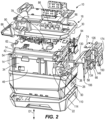
FIG. 2 is an exploded view of the battery pack ofFIG. 1 . -
FIG. 3 is a perspective view of a wall of the battery pack ofFIG. 1 . -
FIG. 4 is another perspective view of the wall ofFIG. 3 . -
FIG. 5 is a partial perspective view of the battery pack ofFIG. 1 . -
FIG. 6 is another partial perspective view of the battery pack ofFIG. 1 . -
FIG. 7 is a cross-sectional view of the battery pack ofFIG. 1 taken along section line 7-7 inFIG. 5 . -
FIG. 8 is another partial perspective view of the battery pack ofFIG. 1 . - Before any embodiments of the disclosure are explained in detail, it is to be understood that the disclosure is not limited in its application to the details of construction and the arrangement of components set forth in the following description or illustrated in the following drawings. The disclosure is capable of other embodiments and of being practiced or of being carried out in various ways. Also, it is to be understood that the phraseology and terminology used herein is for the purpose of description and should not be regarded as limiting.
-
FIGS. 1-7 illustrate abattery pack 10 including a plurality of cells 14 (e.g., pouch cells) positioned within ahousing 18. With reference toFIG. 2 , thehousing 18 includes abase 22, abody 26, and acap 30. Thebattery pack 10 further includes acore box 34 positioned within thehousing 18. Thepouch cells 14 are generally located within thecore box 34. Thecore box 34 is generally rectangular in shape, and includes abase wall 38, anend wall 42, a plurality ofsidewalls 46. Theend wall 42 and thesidewalls 46 project away from thebase wall 38. Opposite theend wall 42, thecore box 34 includes anend void 50. Opposite thebase wall 38, thecore box 34 includes aceiling void 54. In the assembledbattery pack 10, awall 58 takes up theend void 50, and a printedcircuit board 62 takes up theceiling void 58. Various mechanisms relating to thewall 58, components provided on and around thewall 58, and electrical isolation and couplings provided adjacent thewall 58 are described herein. These mechanisms securely and safely mechanically and electrically couple thecells 14 to one another and thecells 14 to the printedcircuit board 62. - In the illustrated embodiment, the
battery pack 10 is a high-performance battery pack including a plurality of lithium-basedcells 14. The illustratedbattery pack 10 includes a plurality of lithium-basedpouch cells 14. Other battery packs may be nickel-based or have differing chemistries and/or structures (e.g., other battery packs may include prismatic cells or cylindrical cells). The illustratedcells 14 are stacked upon one another in thecore box 34 and along a stacking direction D1 between thebase wall 38 and the printedcircuit board 62. Eachcell 14 has acell terminal 66 corresponding to each polarity (e.g., positive, negative) of thecell 14. The illustrated embodiment includes fivecells 14 coupled in series. Eachcell 14 of the illustratedbattery pack 10 has a voltage of approximately 3.6 volts, and the total voltage of thebattery pack 10 is approximately 18 volts. Other electrical arrangements ofcells 14, numbers ofcells 14, voltages ofindividual cells 14, and/or the total voltage of thebattery pack 10 may differ in other embodiments. - As shown in
FIG. 5 , thebattery pack 10 includes afirst lead 70 coupled to acell terminal 66 of one of thecells 14 and asecond lead 74 coupled to acell terminal 66 of another one of thecells 14. Thecells 14 are coupled to one another by terminal-to-terminal connections as described below. Thefirst lead 70 and thesecond lead 74 are each mounted on the printedcircuit board 62 and are each coupled to abattery terminal 78 for connection of thebattery pack 10 to either a charger or a tool (not shown). Thefirst lead 70 and thesecond lead 74 relate to opposite polarities (e.g., thefirst lead 70 corresponds with a positive charge, and thesecond lead 74 corresponds with a negative charge, or vice versa). Referring toFIGS. 1 and2 , thebattery pack 10 includes a pair ofrails 82 which are configured to slidably engage either a charger or a tool to electrically connect thebattery terminals 78 of thebattery pack 10 to the charger or tool. Abutton 86 andtang 90 are configured to hold engagement of thebattery pack 10 and the charger or tool. To disconnect thebattery pack 10 from the charger or tool, thebutton 86 is depressed to release thetang 90 from the charger or tool. A plurality offasteners 94 engage thehousing 18 andwall 58 hold thebattery pack 10 together. - With reference to
FIGS. 2 and5 , thebattery pack 10 further includes a sensing circuit including a plurality oftraces 98 connecting a plurality oftaps 102 to the printedcircuit board 62. Thetraces 98 are each positioned within ajacket 106. In the illustrated embodiment, thetraces 98 andjacket 106 are formed as a flexible circuit capable of deflecting. However, in other embodiments, portions or the entirety of thetraces 98 and/or thejacket 106 may be substantially rigid. - With continued reference to
FIG. 2 , thecore box 34 includes a plurality ofbarbs 110 configured to interact with and secure thecore box 34 to the printedcircuit board 62 and thewall 58. Thebarbs 110 are generally located adjacent theceiling void 54 and theend void 50. Thecore box 34 further includesbarb receivers 114 which are also configured to interact with thewall 58. -
FIGS. 3 and 4 illustrate thewall 58 in detail. Thewall 58 is generally split into a first lateral portion 118 (i.e., a left side) and a second lateral portion 122 (i.e., a right side). Afastener receiver 126 is positioned between the firstlateral portion 118 and the secondlateral portion 122. Thefastener receiver 126 is configured to receive one of thefasteners 94 to secure thewall 58 to thehousing 18. Eachlateral portion wall 58 includes abarb 130 and abarb receiver 134 which each interface withcorresponding barbs 110 andbarb receivers 114 of thecore box 34 to secure thewall 58 to thecore box 34. Thewall 58 is generally planar and has anouter surface 138 andinner surface 142 which are spaced from one another by a thickness T1. - Each
lateral portion wall 58 includes a plurality of cell terminal holes 146. In the assembledbattery pack 10, onecell terminal 66 of onecell 14 is positioned extending through onecell terminal hole 146. Thewall 58 further includes a plurality ofribs 150 which project from theouter surface 138 of thewall 58. Theribs 150 project a second thickness T2 from theouter surface 138. Accordingly, a total thickness of theribs 150 includes both the first thickness T1 and the second thickness T2 such that the rib has a second thickness (T1+T2) that is greater than the first thickness T1. Theribs 150 separateadjacent cell terminals 66 to inhibit contact between adjacent cell terminals and inhibit electrical short circuiting between certain combinations of terminals 66 (e.g., a first terminal of a first cell and a second terminal of a second cell). One of theribs 150 includes areceptacle 154. In the illustrated embodiment, therib 150 includes a pair of spaced apartreceptacles 154. Thewall 58 includes a plurality of tap holes 158 passing through theouter surface 138 but not projecting from theinner surface 142. The tap holes 158 are in communication with tap recesses 162. The tap recesses 162 are recess from theouter surface 138 of thewall 58. Tap through-holes 166 are located within the tap recesses 162 and span the entirety of thewall 58 from theouter surface 138 to theinner surface 142. In the illustrated embodiment, eachtap recess 162 includes three tap through-holes 166 at one lateral side thereof, and three tap through-holes 166 at an opposite lateral side thereof for a total of six tap through-holes 166 pertap recess 162. The illustrated tap through-holes are arranged in opposing triangular pattern. Other numbers and/or arrangements of tap through-holes 166 are possible. - With reference to
FIGS. 5 and6 , thebattery pack 10 includes afuse 170. Thefuse 170 electrically couples acell terminal 66 of acell 14 to the printedcircuit board 62. Thefuse 170 is positioned between thecell terminal 66 and the printedcircuit board 62 such that thefuse 170 can protect the printedcircuit board 62 from damage (e.g., overheating, overvoltage, overcurrent) occurring at thecell terminal 66. Thefuse 170 is electrically conductive. An electricallyinsulative strap 174 is insert molded to thefuse 170. Thestrap 174 is electrically isolates thefuse 170 fromcells 14 andcell terminals 66 other than theconnected cell 14 andcell terminal 66. - The
fuse 170 has a cell-side 170a portion having a first width W1, a board-side portion 170b having a second width W2, and acentral portion 170c between the cell-side portion 170a and theboard side portion 170b. Thecentral portion 170c has a third width W3 which is smaller than the first width W1 and the second width W2. In the illustrated embodiment, the first width W1 and the second width W2 are generally the same. The first width W1 and second width W2 permit thefuse 170 to be robust enough to withstand operating characteristics (e.g., heat, voltage, current), and the third width W3 is dimensioned such that the central portion of thefuse 170 ruptures with unsafe operating characteristics (e.g., overheating, overvoltage, overcurrent). Upon rupture, thefuse 170 does not permit passage of current from theconnected cell terminal 66, and the charge or discharge to/from thebattery pack 10 is halted. - The
fuse 170 includes an encapsulatedportion 170d surrounded by thestrap 174 and afree portion 170e not encapsulated by the strap. Thecell terminal 66 that is electrically coupled to thefuse 170 is coupled to thefree portion 170e of thefuse 170. Thestrap 174 electrically isolates the encapsulatedportion 170d of thefuse 170 fromother cell terminals 66 adjacent the second lateral portion 122 (i.e., the right side) of thewall 58. As illustrated inFIG. 6 , thestrap 174 includes atab 178. Thereceptacle 154 of therib 150 receives thetab 178 of thestrap 174 to align thestrap 174 with thewall 58. In the illustrated embodiment, thestrap 174 includes twotabs 178 which are received by each of thereceptacles 154. - As best illustrated in
FIG. 7 ,cell terminals 66 ofadjacent cells 14 are connected to one another at aninterface 182. Thetaps 102 are electrically coupled to each of the adjacent cells 14 (e.g., afirst cell 14 and a second cell 14) at thesame interface 182. Thetaps 102 pass through the tap holes 158. Thetaps 102 are soldered totraces 98 within thejacket 106 to be coupled to thecircuit board 62. Thetrace 98 electrically couples thetap 102 to the printedcircuit board 62 with thetrace 98 being configured to transmit a signal indicative of at least one of a voltage and a current at theinterface 182 to the printedcircuit board 62. As shown inFIG. 7 , thetap 102, acell terminal 66 of onecell 14, and acell terminal 66 of anothercell 14 are welded to one another at theinterface 182. In the illustrated embodiment, thetap 102, acell terminal 66 of onecell 14, and acell terminal 66 of anothercell 14 are stacked upon one another and laser welded to one another at theinterface 182. Multiple traces 98 are present in thejacket 106, with eachtrace 98 electrically coupling adifferent interface 182 to the printedcircuit board 62. In the illustrated embodiment, thecell terminals 66 are either copper-based or aluminum-based. In the illustrated embodiment, opposingcell terminals 66 at asingle interface 182 are copper-based and aluminum-based, respectively. Thetap 102 has an encapsulatedportion 102a surrounded by thewall 58 and afree portion 102b not encapsulated by thewall 58. Thefree portion 102b is positioned between thewall 58 and acell terminal 66 of afirst cell 14. Thecell terminal 66 of thefirst cell 14 is positioned between thefree portion 102b and acell terminal 66 of asecond cell 14. -
FIGS. 5 and8 illustrate theribs 150 of thewall 58 in detail. Theribs 150 are electrically insulative and protrude from theouter surface 138 of thewall 58 to electrically isolatecell terminals 66 of oneinterface 182 fromcell terminals 66 of anotherinterface 182. Presence of theribs 150 separates thecell terminals 66 prior to securing the position of the cell terminals by welding (e.g., laser welding) of thetabs 102 and twocell terminals 66 at eachinterface 182. In the illustrated embodiment, thewall 58 is molded (e.g., insert molded), and theribs 150 are integrally formed with the wall. In other embodiments, ribs may be otherwise secured to thewall 58. As best illustrated inFIGS. 3 and8 , theribs 150 are positioned betweenterminal holes 146 corresponding tocell terminals 66 that need to be electrically isolated from one another. In the assembly, thecells 14 are stacked in the stacking direction D1 with oppositepolarities cell terminals 66 on eitherlateral side wall 58. Theinterfaces 182 connectpositive cell terminals 66 of onecell 14 tonegative cell terminals 66 of anothercell 14, and vice-versa. This continues down the stacking direction D1, where thelast cell terminal 66 of thebattery pack 10 is connected to thefree portion 170e of thefuse 170. Thefuse 170 is, in turn, connected to thesecond lead 74 and acorresponding battery terminal 78 such that when thebattery pack 10 is coupled to a charger or tool, thebattery pack 10 is configured to receive or emit current to or from the charger or tool. - The
ribs 150 electrically isolate onecell terminal 66 from two directly electrically coupledcell terminals 66. In the stacking direction, thebattery pack 10 includes afirst cell 14 having afirst cell terminal 66, asecond cell 14 having asecond cell terminal 66, and athird cell 14 having athird cell terminal 66. Eachcell terminal 66 extends through a corresponding and dedicatedterminal hole 146 of the wall 58 (e.g., onecell terminal 66 extends through one terminal hole 146). Therib 150 protrudes from thewall 58 to inhibit contact and thus electrical short circuiting between thethird cell terminal 66 and either one of thefirst cell terminal 66 and thesecond cell terminal 66. Therib 150 electrically isolates thethird cell terminal 66 from thefirst cell terminal 66 and thesecond cell terminal 66.. - Although the disclosure has been described in detail with reference to certain preferred embodiments, variations and modifications exist within the scope and spirit of one or more independent aspects of the disclosure as described. When used in this specification and claims, the terms "comprises" and "comprising" and variations thereof mean that the specified features, steps or integers are included. The terms are not to be interpreted to exclude the presence of other features, steps or components.
- Representative features are set out in the following clauses, which stand alone or may be combined, in any combination, with one or more features disclosed in the text and/or drawings of the specification.
- 1. A battery pack comprising:
- a control circuit board;
- a first cell having a first terminal electrically coupled to the control circuit board;
- a second cell electrically coupled to the first cell and having a second terminal;
- a fuse electrically coupling the second terminal to the control circuit board, the fuse being positioned between the second terminal and the control circuit board;
- an electrically insulative strap molded to the fuse, the strap electrically isolates the fuse from the first cell.
- 2. The battery pack of clause 1, wherein the fuse has a cell-side portion having a first width, a board-side portion having a second width, and a central portion between the cell-side portion and the board-side portion having a third width smaller than the first width and the second width.
- 3. The battery pack of clause 1, wherein the fuse has an encapsulated portion surrounded by the strap and a free portion not encapsulated by the strap.
- 4. The battery pack of clause 3, wherein the second terminal is coupled to the fuse at the free portion.
- 5. The battery pack of clause 3, wherein the fuse has a cell-side portion, a board-side portion, and a central portion between the cell-side portion and the board-side portion, the central portion being part of the free portion of the fuse spaced from the strap.
- 6. The battery pack of clause 1, further comprising a core box having a wall with a receptacle, the receptacle receiving a tab of the strap to align the strap with the wall.
- 7. The battery pack of clause 1, further comprising a third cell with a third terminal, the third cell being electrically coupled with the first cell and the second cell, the third terminal being electrically isolated from the second terminal by the strap.
- 8. A battery pack comprising:
- a control circuit board;
- a cell electrically coupled to the control circuit board and having a first terminal;
- another cell having a second terminal electrically coupled to the first terminal at an interface;
- a tap electrically coupled to the first terminal and the second terminal at the interface;
- an electrically insulative wall molded to the tap, the wall secures the position of the tap; and
- a trace electrically coupling the tap to the control circuit board, the trace being configured to transmit a signal indicative of at least one of a voltage and a current at the interface to the control circuit board.
- 9. The battery pack of clause 8, wherein the tap, first terminal, and second terminal are welded to one another at the interface.
- 10. The battery pack of clause 9, wherein the tap is soldered to the trace.
- 11. The battery pack of clause 8, further comprising yet another cell having a yet another terminal, a further cell having a further terminal, and a another tap electrically coupled to the yet another terminal and the further terminal at a second interface, the second tap being electrically coupled to the second trace, both the trace and the second trace being provided within a jacket.
- 12. The battery pack of clause 8, wherein at least one of the first terminal and the second terminal is either copper-based or aluminum-based.
- 13. The battery pack of clause 12, wherein the first terminal is copper-based, and the second terminal is aluminum-based.
- 14. The battery pack of clause 8, wherein the tap has an encapsulated portion surrounded by the wall and a free portion not encapsulated by the wall, the free portion is positioned between the wall and the first terminal, and the first terminal is positioned between the tap and the second terminal.
- 15. A battery pack comprising:
- a first cell having a first terminal;
- a second cell having a second terminal directly electrically coupled to the first cell at an interface;
- a third cell having a third terminal;
- a core box receiving the first cell, the second cell, and the third cell therein;
- a wall coupled to the core box, the wall comprising:
- a first terminal hole through which the first terminal extends,
- a second terminal hole through which the second terminal extends,
- a third terminal hole through which the third terminal extends, and
- an electrically insulative rib protruding from the wall to inhibit contact and thus electrical short circuiting between the third terminal and either of the first terminal and the second terminal, the rib electrically isolates the third terminal from the first terminal and the second terminal.
- 16. The battery pack of clause 15, wherein the wall is generally planar and has a first thickness.
- 17. The battery pack of clause 16, wherein the rib has a second thickness greater than the first thickness.
- 18. The battery pack of clause 15, wherein the second cell has an auxiliary second cell terminal, the third cell has an auxiliary third cell terminal, and the third terminal is indirectly coupled to the first cell and the second cell through an auxiliary interface between the auxiliary second cell terminal and the auxiliary third cell terminal.
- 19. The battery pack of clause 15, wherein the wall is molded, and the rib is integrally formed with the wall.
- 20. The battery pack of clause 15, wherein the rib is positioned between the first terminal hole and the second terminal hole.
Claims (15)
- A battery pack comprising:a control circuit board;a first cell having a first terminal electrically coupled to the control circuit board;a second cell electrically coupled to the first cell and having a second terminal;a fuse electrically coupling the second terminal to the control circuit board, the fuse being positioned between the second terminal and the control circuit board;an electrically insulative strap molded to the fuse, the strap electrically isolates the fuse from the first cell.
- The battery pack of claim 1, wherein the fuse has a cell-side portion having a first width, a board-side portion having a second width, and a central portion between the cell-side portion and the board-side portion having a third width smaller than the first width and the second width.
- The battery pack of claim 1, wherein the fuse has an encapsulated portion surrounded by the strap and a free portion not encapsulated by the strap, preferably wherein the second terminal is coupled to the fuse at the free portion.
- The battery pack of claim 3, wherein the fuse has a cell-side portion, a board-side portion, and a central portion between the cell-side portion and the board-side portion, the central portion being part of the free portion of the fuse spaced from the strap.
- The battery pack of any preceding claim, further comprising a core box having a wall with a receptacle, the receptacle receiving a tab of the strap to align the strap with the wall.
- The battery pack of any preceding claim, further comprising a third cell with a third terminal, the third cell being electrically coupled with the first cell and the second cell, the third terminal being electrically isolated from the second terminal by the strap.
- A battery pack comprising:a control circuit board;a cell electrically coupled to the control circuit board and having a first terminal;another cell having a second terminal electrically coupled to the first terminal at an interface;a tap electrically coupled to the first terminal and the second terminal at the interface;an electrically insulative wall molded to the tap, the wall secures the position of the tap; anda trace electrically coupling the tap to the control circuit board, the trace being configured to transmit a signal indicative of at least one of a voltage and a current at the interface to the control circuit board.
- The battery pack of claim 7, wherein the tap, first terminal, and second terminal are welded to one another at the interface, preferably wherein the tap is soldered to the trace.
- The battery pack of claim 7 or 8, further comprising yet another cell having a yet another terminal, a further cell having a further terminal, and a another tap electrically coupled to the yet another terminal and the further terminal at a second interface, the second tap being electrically coupled to the second trace, both the trace and the second trace being provided within a jacket, and/or wherein at least one of the first terminal and the second terminal is either copper-based or aluminum-based.
- The battery pack of claim 9, wherein the first terminal is copper-based, and the second terminal is aluminum-based.
- The battery pack of any one of claims 7 to 10, wherein the tap has an encapsulated portion surrounded by the wall and a free portion not encapsulated by the wall, the free portion is positioned between the wall and the first terminal, and the first terminal is positioned between the tap and the second terminal.
- A battery pack comprising:a first cell having a first terminal;a second cell having a second terminal directly electrically coupled to the first cell at an interface;a third cell having a third terminal;a core box receiving the first cell, the second cell, and the third cell therein;a wall coupled to the core box, the wall comprising:a first terminal hole through which the first terminal extends,a second terminal hole through which the second terminal extends,a third terminal hole through which the third terminal extends, andan electrically insulative rib protruding from the wall to inhibit contact and thus electrical short circuiting between the third terminal and either of the first terminal and the second terminal, the rib electrically isolates the third terminal from the first terminal and the second terminal.
- The battery pack of claim 12, wherein the wall is generally planar and has a first thickness, preferably wherein the rib has a second thickness greater than the first thickness.
- The battery pack of claim 12 or 13, wherein the second cell has an auxiliary second cell terminal, the third cell has an auxiliary third cell terminal, and the third terminal is indirectly coupled to the first cell and the second cell through an auxiliary interface between the auxiliary second cell terminal and the auxiliary third cell terminal.
- The battery pack of claim 12, 13 or 14, wherein the wall is molded, and the rib is integrally formed with the wall, and/or wherein the rib is positioned between the first terminal hole and the second terminal hole.
Applications Claiming Priority (1)
| Application Number | Priority Date | Filing Date | Title |
|---|---|---|---|
| US202263430602P | 2022-12-06 | 2022-12-06 |
Publications (2)
| Publication Number | Publication Date |
|---|---|
| EP4383417A2 true EP4383417A2 (en) | 2024-06-12 |
| EP4383417A3 EP4383417A3 (en) | 2024-08-07 |
Family
ID=89073024
Family Applications (1)
| Application Number | Title | Priority Date | Filing Date |
|---|---|---|---|
| EP23213616.8A Pending EP4383417A3 (en) | 2022-12-06 | 2023-12-01 | Battery pack |
Country Status (4)
| Country | Link |
|---|---|
| US (1) | US20240186640A1 (en) |
| EP (1) | EP4383417A3 (en) |
| JP (1) | JP2024081613A (en) |
| CN (1) | CN222214315U (en) |
Families Citing this family (3)
| Publication number | Priority date | Publication date | Assignee | Title |
|---|---|---|---|---|
| USD1123821S1 (en) * | 2024-06-13 | 2026-04-28 | Jiangsu Dongcheng Tools Technology Co., Ltd. | Battery pack |
| USD1117001S1 (en) * | 2025-04-14 | 2026-03-10 | Lianpeng Chen | Battery pack |
| USD1117000S1 (en) * | 2025-04-14 | 2026-03-10 | Lianpeng Chen | Battery pack |
Family Cites Families (12)
| Publication number | Priority date | Publication date | Assignee | Title |
|---|---|---|---|---|
| JPH05266928A (en) * | 1992-03-16 | 1993-10-15 | Sanyo Electric Co Ltd | Packed battery |
| JPH09153352A (en) * | 1995-11-30 | 1997-06-10 | Canon Inc | Electronic device battery pack |
| JP4757508B2 (en) * | 2005-03-01 | 2011-08-24 | 日本電気株式会社 | Electrical device assembly |
| JP2013191286A (en) * | 2012-03-12 | 2013-09-26 | Max Co Ltd | Battery pack |
| DE102016219098B4 (en) * | 2016-09-30 | 2024-11-28 | Volkswagen Aktiengesellschaft | battery disconnect device |
| CN106450098B (en) * | 2016-12-17 | 2023-04-18 | 北京理工大学 | High-energy-density battery box structure easy to maintain |
| JP6926770B2 (en) * | 2017-07-21 | 2021-08-25 | 工機ホールディングス株式会社 | Battery packs and electrical equipment using battery packs |
| JP6724062B2 (en) * | 2018-04-18 | 2020-07-15 | 本田技研工業株式会社 | Battery pack |
| EP3817087B1 (en) * | 2018-06-26 | 2024-07-03 | SANYO Electric Co., Ltd. | Battery system, and electric vehicle and electric storage device including battery system |
| US20230010270A1 (en) * | 2020-03-31 | 2023-01-12 | Koki Holdings Co., Ltd. | Battery pack and electrical apparatus using same |
| EP3965223A1 (en) * | 2020-07-17 | 2022-03-09 | Dongguan Poweramp Technology Limited | Cell module and battery pack |
| JP7576223B2 (en) * | 2021-01-19 | 2024-10-31 | 株式会社オートネットワーク技術研究所 | Wiring Module |
-
2023
- 2023-11-29 US US18/522,472 patent/US20240186640A1/en active Pending
- 2023-12-01 EP EP23213616.8A patent/EP4383417A3/en active Pending
- 2023-12-01 JP JP2023204061A patent/JP2024081613A/en active Pending
- 2023-12-06 CN CN202323312257.4U patent/CN222214315U/en active Active
Also Published As
| Publication number | Publication date |
|---|---|
| EP4383417A3 (en) | 2024-08-07 |
| US20240186640A1 (en) | 2024-06-06 |
| JP2024081613A (en) | 2024-06-18 |
| CN222214315U (en) | 2024-12-20 |
Similar Documents
| Publication | Publication Date | Title |
|---|---|---|
| EP4383417A2 (en) | Battery pack | |
| EP1695401B1 (en) | Lead member and secondary battery module with the same | |
| EP2207222B1 (en) | Battery pack | |
| US8974950B2 (en) | Connection structure for battery module, battery module and method of connecting terminals of battery modules | |
| CN104704649B (en) | Battery module with busbar assembly and the battery pack including the battery module | |
| US9397327B2 (en) | Battery connecting assembly | |
| KR20240081474A (en) | Battery module | |
| US8481183B2 (en) | Secondary battery | |
| EP3154108B1 (en) | Battery module and battery pack including same | |
| KR102866659B1 (en) | A battery module with improved assembly structure of voltage sensing components and A battery pack including the same | |
| EP4064417B1 (en) | Battery module in which connection between electrode lead and voltage sensing member is simplified, and battery pack including the same | |
| EP1928044A1 (en) | Connection cap for a rechargeable battery | |
| EP2064759A1 (en) | Battery module interface | |
| KR102789863B1 (en) | Connector | |
| CN101164179A (en) | Improved middle or large-sized battery pack with improved safety | |
| EP4109662A1 (en) | Battery module, battery pack comprising same, and vehicle | |
| US12051868B2 (en) | Connector, battery management unit and battery pack | |
| EP4462584A1 (en) | Battery module with improved flame path, and battery pack comprising same | |
| JP7854133B2 (en) | Energy storage device | |
| EP4553981A1 (en) | End cover assembly, battery assembly, battery, and electrical device | |
| EP4447212A1 (en) | Rechargeable battery module | |
| KR20260021236A (en) | A bus bar for inter battery cell connection and a bus bar set thereof | |
| CN120814109A (en) | Battery cell, battery and electricity utilization device | |
| US20030072992A1 (en) | Battery pack |
Legal Events
| Date | Code | Title | Description |
|---|---|---|---|
| PUAI | Public reference made under article 153(3) epc to a published international application that has entered the european phase |
Free format text: ORIGINAL CODE: 0009012 |
|
| STAA | Information on the status of an ep patent application or granted ep patent |
Free format text: STATUS: REQUEST FOR EXAMINATION WAS MADE |
|
| 17P | Request for examination filed |
Effective date: 20231201 |
|
| AK | Designated contracting states |
Kind code of ref document: A2 Designated state(s): AL AT BE BG CH CY CZ DE DK EE ES FI FR GB GR HR HU IE IS IT LI LT LU LV MC ME MK MT NL NO PL PT RO RS SE SI SK SM TR |
|
| PUAL | Search report despatched |
Free format text: ORIGINAL CODE: 0009013 |
|
| AK | Designated contracting states |
Kind code of ref document: A3 Designated state(s): AL AT BE BG CH CY CZ DE DK EE ES FI FR GB GR HR HU IE IS IT LI LT LU LV MC ME MK MT NL NO PL PT RO RS SE SI SK SM TR |
|
| RIC1 | Information provided on ipc code assigned before grant |
Ipc: H01M 50/583 20210101ALI20240704BHEP Ipc: H01M 50/553 20210101ALI20240704BHEP Ipc: H01M 50/502 20210101ALI20240704BHEP Ipc: H01M 50/519 20210101ALI20240704BHEP Ipc: H01M 50/529 20210101ALI20240704BHEP Ipc: H01M 50/284 20210101ALI20240704BHEP Ipc: H01M 50/247 20210101ALI20240704BHEP Ipc: H01M 50/211 20210101AFI20240704BHEP |