EP4383412A2 - Battery cell and battery pack including the same - Google Patents
Battery cell and battery pack including the same Download PDFInfo
- Publication number
- EP4383412A2 EP4383412A2 EP23212051.9A EP23212051A EP4383412A2 EP 4383412 A2 EP4383412 A2 EP 4383412A2 EP 23212051 A EP23212051 A EP 23212051A EP 4383412 A2 EP4383412 A2 EP 4383412A2
- Authority
- EP
- European Patent Office
- Prior art keywords
- terminal
- guide line
- cap assembly
- battery
- guide
- Prior art date
- Legal status (The legal status is an assumption and is not a legal conclusion. Google has not performed a legal analysis and makes no representation as to the accuracy of the status listed.)
- Pending
Links
Images


Classifications
-
- H—ELECTRICITY
- H01—ELECTRIC ELEMENTS
- H01M—PROCESSES OR MEANS, e.g. BATTERIES, FOR THE DIRECT CONVERSION OF CHEMICAL ENERGY INTO ELECTRICAL ENERGY
- H01M50/00—Constructional details or processes of manufacture of the non-active parts of electrochemical cells other than fuel cells, e.g. hybrid cells
- H01M50/50—Current conducting connections for cells or batteries
- H01M50/543—Terminals
- H01M50/564—Terminals characterised by their manufacturing process
- H01M50/567—Terminals characterised by their manufacturing process by fixing means, e.g. screws, rivets or bolts
-
- H—ELECTRICITY
- H01—ELECTRIC ELEMENTS
- H01M—PROCESSES OR MEANS, e.g. BATTERIES, FOR THE DIRECT CONVERSION OF CHEMICAL ENERGY INTO ELECTRICAL ENERGY
- H01M50/00—Constructional details or processes of manufacture of the non-active parts of electrochemical cells other than fuel cells, e.g. hybrid cells
- H01M50/50—Current conducting connections for cells or batteries
- H01M50/543—Terminals
- H01M50/552—Terminals characterised by their shape
- H01M50/553—Terminals adapted for prismatic, pouch or rectangular cells
-
- H—ELECTRICITY
- H01—ELECTRIC ELEMENTS
- H01M—PROCESSES OR MEANS, e.g. BATTERIES, FOR THE DIRECT CONVERSION OF CHEMICAL ENERGY INTO ELECTRICAL ENERGY
- H01M50/00—Constructional details or processes of manufacture of the non-active parts of electrochemical cells other than fuel cells, e.g. hybrid cells
- H01M50/10—Primary casings; Jackets or wrappings
- H01M50/102—Primary casings; Jackets or wrappings characterised by their shape or physical structure
- H01M50/103—Primary casings; Jackets or wrappings characterised by their shape or physical structure prismatic or rectangular
-
- H—ELECTRICITY
- H01—ELECTRIC ELEMENTS
- H01M—PROCESSES OR MEANS, e.g. BATTERIES, FOR THE DIRECT CONVERSION OF CHEMICAL ENERGY INTO ELECTRICAL ENERGY
- H01M50/00—Constructional details or processes of manufacture of the non-active parts of electrochemical cells other than fuel cells, e.g. hybrid cells
- H01M50/10—Primary casings; Jackets or wrappings
- H01M50/147—Lids or covers
- H01M50/148—Lids or covers characterised by their shape
- H01M50/15—Lids or covers characterised by their shape for prismatic or rectangular cells
-
- H—ELECTRICITY
- H01—ELECTRIC ELEMENTS
- H01M—PROCESSES OR MEANS, e.g. BATTERIES, FOR THE DIRECT CONVERSION OF CHEMICAL ENERGY INTO ELECTRICAL ENERGY
- H01M50/00—Constructional details or processes of manufacture of the non-active parts of electrochemical cells other than fuel cells, e.g. hybrid cells
- H01M50/10—Primary casings; Jackets or wrappings
- H01M50/172—Arrangements of electric connectors penetrating the casing
- H01M50/174—Arrangements of electric connectors penetrating the casing adapted for the shape of the cells
- H01M50/176—Arrangements of electric connectors penetrating the casing adapted for the shape of the cells for prismatic or rectangular cells
-
- H—ELECTRICITY
- H01—ELECTRIC ELEMENTS
- H01M—PROCESSES OR MEANS, e.g. BATTERIES, FOR THE DIRECT CONVERSION OF CHEMICAL ENERGY INTO ELECTRICAL ENERGY
- H01M50/00—Constructional details or processes of manufacture of the non-active parts of electrochemical cells other than fuel cells, e.g. hybrid cells
- H01M50/20—Mountings; Secondary casings or frames; Racks, modules or packs; Suspension devices; Shock absorbers; Transport or carrying devices; Holders
- H01M50/204—Racks, modules or packs for multiple batteries or multiple cells
- H01M50/207—Racks, modules or packs for multiple batteries or multiple cells characterised by their shape
- H01M50/209—Racks, modules or packs for multiple batteries or multiple cells characterised by their shape adapted for prismatic or rectangular cells
-
- H—ELECTRICITY
- H01—ELECTRIC ELEMENTS
- H01M—PROCESSES OR MEANS, e.g. BATTERIES, FOR THE DIRECT CONVERSION OF CHEMICAL ENERGY INTO ELECTRICAL ENERGY
- H01M50/00—Constructional details or processes of manufacture of the non-active parts of electrochemical cells other than fuel cells, e.g. hybrid cells
- H01M50/50—Current conducting connections for cells or batteries
- H01M50/502—Interconnectors for connecting terminals of adjacent batteries; Interconnectors for connecting cells outside a battery casing
-
- H—ELECTRICITY
- H01—ELECTRIC ELEMENTS
- H01M—PROCESSES OR MEANS, e.g. BATTERIES, FOR THE DIRECT CONVERSION OF CHEMICAL ENERGY INTO ELECTRICAL ENERGY
- H01M50/00—Constructional details or processes of manufacture of the non-active parts of electrochemical cells other than fuel cells, e.g. hybrid cells
- H01M50/50—Current conducting connections for cells or batteries
- H01M50/502—Interconnectors for connecting terminals of adjacent batteries; Interconnectors for connecting cells outside a battery casing
- H01M50/507—Interconnectors for connecting terminals of adjacent batteries; Interconnectors for connecting cells outside a battery casing comprising an arrangement of two or more busbars within a container structure, e.g. busbar modules
-
- H—ELECTRICITY
- H01—ELECTRIC ELEMENTS
- H01M—PROCESSES OR MEANS, e.g. BATTERIES, FOR THE DIRECT CONVERSION OF CHEMICAL ENERGY INTO ELECTRICAL ENERGY
- H01M50/00—Constructional details or processes of manufacture of the non-active parts of electrochemical cells other than fuel cells, e.g. hybrid cells
- H01M50/50—Current conducting connections for cells or batteries
- H01M50/502—Interconnectors for connecting terminals of adjacent batteries; Interconnectors for connecting cells outside a battery casing
- H01M50/514—Methods for interconnecting adjacent batteries or cells
- H01M50/516—Methods for interconnecting adjacent batteries or cells by welding, soldering or brazing
-
- H—ELECTRICITY
- H01—ELECTRIC ELEMENTS
- H01M—PROCESSES OR MEANS, e.g. BATTERIES, FOR THE DIRECT CONVERSION OF CHEMICAL ENERGY INTO ELECTRICAL ENERGY
- H01M50/00—Constructional details or processes of manufacture of the non-active parts of electrochemical cells other than fuel cells, e.g. hybrid cells
- H01M50/50—Current conducting connections for cells or batteries
- H01M50/543—Terminals
- H01M50/547—Terminals characterised by the disposition of the terminals on the cells
- H01M50/55—Terminals characterised by the disposition of the terminals on the cells on the same side of the cell
-
- H—ELECTRICITY
- H01—ELECTRIC ELEMENTS
- H01M—PROCESSES OR MEANS, e.g. BATTERIES, FOR THE DIRECT CONVERSION OF CHEMICAL ENERGY INTO ELECTRICAL ENERGY
- H01M50/00—Constructional details or processes of manufacture of the non-active parts of electrochemical cells other than fuel cells, e.g. hybrid cells
- H01M50/50—Current conducting connections for cells or batteries
- H01M50/543—Terminals
- H01M50/552—Terminals characterised by their shape
- H01M50/553—Terminals adapted for prismatic, pouch or rectangular cells
- H01M50/557—Plate-shaped terminals
-
- H—ELECTRICITY
- H01—ELECTRIC ELEMENTS
- H01M—PROCESSES OR MEANS, e.g. BATTERIES, FOR THE DIRECT CONVERSION OF CHEMICAL ENERGY INTO ELECTRICAL ENERGY
- H01M50/00—Constructional details or processes of manufacture of the non-active parts of electrochemical cells other than fuel cells, e.g. hybrid cells
- H01M50/50—Current conducting connections for cells or batteries
- H01M50/543—Terminals
- H01M50/564—Terminals characterised by their manufacturing process
- H01M50/566—Terminals characterised by their manufacturing process by welding, soldering or brazing
-
- Y—GENERAL TAGGING OF NEW TECHNOLOGICAL DEVELOPMENTS; GENERAL TAGGING OF CROSS-SECTIONAL TECHNOLOGIES SPANNING OVER SEVERAL SECTIONS OF THE IPC; TECHNICAL SUBJECTS COVERED BY FORMER USPC CROSS-REFERENCE ART COLLECTIONS [XRACs] AND DIGESTS
- Y02—TECHNOLOGIES OR APPLICATIONS FOR MITIGATION OR ADAPTATION AGAINST CLIMATE CHANGE
- Y02E—REDUCTION OF GREENHOUSE GAS [GHG] EMISSIONS, RELATED TO ENERGY GENERATION, TRANSMISSION OR DISTRIBUTION
- Y02E60/00—Enabling technologies; Technologies with a potential or indirect contribution to GHG emissions mitigation
- Y02E60/10—Energy storage using batteries
Definitions
- Embodiments of the present invention provide a battery cell in which a center of a rivet terminal is easily identifiable, and a battery pack including the battery cell.
- the guide line may be parallel to a length direction of the cap assembly.
- the bus bars 40 may electrically connect the positive electrode terminal and the negative electrode terminal of different ones of the battery cells 10.
- the bus bars 40 may connect the plurality of battery cells 10 in series and/or in parallel. To this end, the plurality of bus bars 40 may be provided.
- the bus bar 40 may electrically connect the battery cells 10 that are not adjacent to each other from among the battery cells 10 arranged in a line.
- the bus bar 40 may electrically connect a positive electrode terminal of one battery cell 10 and a positive electrode terminal or a negative electrode terminal of another battery cell 10.
- the bus bar 40 may also electrically connect a negative electrode terminal of one battery cell 10 and a positive electrode terminal or a negative electrode terminal of another battery cell 10.
- the bus bar 40 may be connected to the positive electrode terminal and the negative electrode terminal by laser welding.
- the bus bar 40 may be insulated from regions other than the positive electrode terminal and the negative electrode terminal by the bus bar holder 30.
- the circuit board 50 is disposed between the bus bars 40 and the top plate 26.
- a portion of the bus bars 40 may be cut to a certain size such that a probe for measuring low resistance may contact a terminal.
- the cut portion is defined as a cutout portion 42 and is shown in detail in FIG. 4 .
- FIGS. 6 and 7 are plan views illustrating a cell terminal according to other embodiments of the present invention.
Landscapes
- Chemical & Material Sciences (AREA)
- Chemical Kinetics & Catalysis (AREA)
- Electrochemistry (AREA)
- General Chemical & Material Sciences (AREA)
- Engineering & Computer Science (AREA)
- Manufacturing & Machinery (AREA)
- Connection Of Batteries Or Terminals (AREA)
- Battery Mounting, Suspending (AREA)
Abstract
Description
- Aspects of embodiments of the present invention relate to a battery cell and a battery pack including the same.
- Generally, a battery pack includes a plurality of battery cells, bus bars electrically connecting the battery cells to each other and to the outside, and a circuit board that is electrically connected to the bus bars and has various circuits and components mounted thereon. Each battery cell includes a negative electrode terminal and a positive electrode terminal. The bus bars may be electrically connected to the terminals of the battery cells by laser welding. In this case, to ensure welding quality after welding, a partially open portion should be present between the bus bar and the terminal before welding. This allows for the welding quality to be checked by using a probe for measuring low resistance.
- When a rivet terminal is used as a terminal of a battery cell, a welding position should be accurate so that the rivet terminal is not affected during laser welding. However, in a process of stacking a plurality of cells, it is difficult for a position of a cell terminal to maintain an accurate distance (or an accurate position) due to accumulated tolerances and the like. In addition, because the rivet terminal is covered by the bus bar during welding, it is difficult to check welding quality because an exact position of the rivet terminal is not known.
- The above information disclosed in this background section is for enhancement of understanding of the background of the present invention, and therefore, it may contain information that does not constitute the related (or prior) art.
- Embodiments of the present invention provide a battery cell in which a center of a rivet terminal is easily identifiable, and a battery pack including the battery cell.
- A battery cell, according to an embodiment of the present invention, includes an electrode assembly and a cap assembly. The cap assembly includes: a terminal plate; a negative electrode terminal; and a positive electrode terminal. The negative electrode terminal and the positive electrode terminal respectively include a rivet terminal electrically connecting the terminal plate and the electrode assembly, and each of the terminal plates has a guide line on a plate surface thereof and passing through a center of the rivet terminal.
- The guide line may be parallel to a length direction of the cap assembly.
- The guide line may be perpendicular to a length direction of the cap assembly.
- The guide line may include: a first guide line parallel to a length direction of the cap assembly; and a second guide line perpendicular to the length direction of the cap assembly.
- The guide line may further include a plurality of third guide lines spaced apart from the first guide line and the second guide line.
- The first to third guide lines may be spaced apart from each other at equal intervals.
- The guide line may be formed through laser marking or mechanical marking to have a preferred depth of about 0.01 mm or less.
- A battery pack, according to an embodiment of the present invention, includes: a plurality of battery cells; a plurality of bus bars; and a cell frame supporting the battery cells. Each of the battery cells includes: a cap assembly including a terminal plate, a negative electrode terminal, and a positive electrode terminal. Each of the negative electrode terminal and the positive electrode terminal includes a rivet terminal electrically connecting the respective terminal plate and an electrode assembly. The bus bars are electrically connected to the terminal plates, each of the terminal plates has a guide line on a plate surface thereof and passing through a center of the rivet terminal.
- One side of at least one of the bus bars may have a cutout portion through which the guide line is exposed.
- The guide line may be parallel to a length direction of the cap assembly.
- The guide line may be perpendicular to a length direction of the cap assembly.
- The guide line may include: a first guide line parallel to a length direction of the cap assembly; and a second guide line perpendicular to the length direction of the cap assembly.
- The guide line may further include a plurality of third guide lines spaced apart from the first guide line and the second guide line.
- The first to third guide lines may be spaced apart from each other at equal intervals.
- Each of the guide lines may be formed through laser marking or mechanical marking to have a preferred depth of about 0.01 mm or less.
- All embodiments described in this specification may be advantageously combined with one another to the extent that their respective features are compatible. In particular, the expressions "according to an embodiment," "in an embodiment," "an embodiment of the invention provides" etc. mean that the respective features may or may not be part of specific embodiments of the present invention.
-
-
FIG. 1 is an exploded perspective view illustrating a battery pack according to an embodiment of the present invention. -
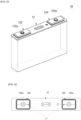
FIG. 2 is a perspective view illustrating a battery cell according to an embodiment of the present invention. -
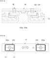
FIG. 3 is a plan view illustrating a cell terminal of the battery cell shown inFIG. 2 . -
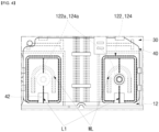
FIG. 4 is a plan view illustrating a welding state between the cell terminal shown inFIG. 3 and a bus bar. -
FIG. 5 is a cross-sectional view illustrating the welding state between the cell terminal and the bus bar shown inFIG. 4 . -
FIG. 6 is a plan view illustrating a cell terminal according to another embodiment of the present invention. -
FIG. 7 is a plan view illustrating a cell terminal according to another embodiment of the present invention. - Embodiments of the present invention are provided to more completely describe the present invention to those having ordinary skill in the art. The following embodiments may be modified into various different forms, and the scope of the present invention is not limited to the following embodiments. Rather, the embodiments are provided so that the present disclosure will be thorough and complete and will convey the aspects and features of the present invention to those skilled in the art.
- It will be understood that when an element or layer is referred to as being "on," "connected to," or "coupled to" another element or layer, it may be directly on, connected, or coupled to the other element or layer or one or more intervening elements or layers may also be present. When an element or layer is referred to as being "directly on," "directly connected to," or "directly coupled to" another element or layer, there are no intervening elements or layers present. For example, when a first element is described as being "coupled" or "connected" to a second element, the first element may be directly coupled or connected to the second element or the first element may be indirectly coupled or connected to the second element via one or more intervening elements.
- In the figures, dimensions of the various elements, layers, etc. may be exaggerated for clarity of illustration. The same reference numerals designate the same elements. As used herein, the term "and/or" includes any and all combinations of one or more of the associated listed items. Further, the use of "may" when describing embodiments of the present invention relates to "one or more embodiments of the present invention." Expressions, such as "at least one of' and "any one of," when preceding a list of elements, modify the entire list of elements and do not modify the individual elements of the list. For example, the expression "at least one of a, b, or c" indicates only a, only b, only c, both a and b, both a and c, both b and c, all of a, b, and c, or variations thereof. As used herein, the terms "use," "using," and "used" may be considered synonymous with the terms "utilize," "utilizing," and "utilized," respectively. As used herein, the terms "substantially," "about," and similar terms are used as terms of approximation and not as terms of degree, and are intended to account for the inherent variations in measured or calculated values that would be recognized by those of ordinary skill in the art.
- It will be understood that, although the terms first, second, third, etc. may be used herein to describe various elements, components, regions, layers, and/or sections, these elements, components, regions, layers, and/or sections should not be limited by these terms. These terms are used to distinguish one element, component, region, layer, or section from another element, component, region, layer, or section. Thus, a first element, component, region, layer, or section discussed below could be termed a second element, component, region, layer, or section without departing from the teachings of example embodiments.
- Spatially relative terms, such as "beneath," "below," "lower," "above," "upper," and the like, may be used herein for ease of description to describe one element or feature's relationship to another element(s) or feature(s) as illustrated in the figures. It will be understood that the spatially relative terms are intended to encompass different orientations of the device in use or operation in addition to the orientation depicted in the figures. For example, if the device in the figures is turned over, elements described as "below" or "beneath" other elements or features would then be oriented "above" or "over" the other elements or features. Thus, the term "below" may encompass both an orientation of above and below. The device may be otherwise oriented (rotated 90 degrees or at other orientations), and the spatially relative descriptors used herein should be interpreted accordingly.
- The terminology used herein is for the purpose of describing embodiments of the present invention and is not intended to be limiting of the present invention. As used herein, the singular forms "a" and "an" are intended to include the plural forms as well, unless the context clearly indicates otherwise. It will be further understood that the terms "includes," "including," "comprises," and/or "comprising," when used in this specification, specify the presence of stated features, integers, steps, operations, elements, and/or components but do not preclude the presence or addition of one or more other features, integers, steps, operations, elements, components, and/or groups thereof.
- Hereinafter, a battery pack, according to an embodiment of the present invention, will be described in detail with reference to the accompanying drawings.
-
FIG. 1 is an exploded perspective view illustrating a battery pack according to an embodiment of the present invention, andFIG. 2 is a perspective view illustrating a battery cell according to one embodiment of the present invention. - As shown in
FIG. 1 , abattery pack 1, according to an embodiment of the present invention, may include a plurality ofbattery cells 10, acell frame 20 for arranging and supporting thebattery cells 10, a plurality ofbus bars 40 electrically connecting thebattery cells 10, and abus bar holder 30 for supporting the bus bars 40. In addition, thebattery pack 1 may further include ahybrid circuit board 50 on which various circuits and components are mounted. One or more of the bus bars 40 may be electrically connected to thecircuit board 50, and thecircuit board 50 may be electrically connected to the outside of thebattery pack 1 through a separate connector. Thebattery pack 1 may be referred to as a battery module. - The
battery cell 10 may have a rectangular parallelepiped shape, and the plurality ofbattery cells 10 may be arranged in a line in a certain direction (e.g., in a stacking direction). Each of thebattery cells 10 may be arranged such that relatively wide plate (or flat) surfaces face each other. Thecell frame 20 is provided to arrange thebattery cells 10. Eachbattery cell 10 may include a case having a rectangular parallelepiped shape, an electrode assembly accommodated inside the case together with an electrolyte, and acap assembly 12 for sealing the case. - The electrode assembly may be formed by sequentially winding or stacking a negative electrode plate, a separator, and a positive electrode plate. The negative electrode plate may have a negative electrode active material, such as graphite or carbon, coated or applied on a metal foil made of copper, a copper alloy, nickel, or a nickel alloy. The positive electrode plate may have an active material, such as a transition metal oxide, coated or applied on a metal foil made of aluminum or an aluminum alloy. An uncoated portion, which is a region on which the corresponding active material is not applied, may be formed on each of the negative electrode plate and the positive electrode plate. A negative electrode tab may be connected to a negative electrode uncoated portion, and a positive electrode tab may be connected to a positive electrode uncoated portion. The negative electrode tab and the positive electrode tab, connected in this way, may be respectively electrically connected to a negative electrode terminal and a positive electrode terminal formed in the
cap assembly 12. The negative electrode terminal and the positive electrode terminal, formed in thecap assembly 12, are electrically connected to the bus bars 40. - The
cell frame 20 may include a pair ofend plates 22 in contact with thebattery cells 10 at both (e.g., opposite) end portions along the arrangement direction of thebattery cells 10, a pair ofside plates 24 orthogonally coupled to (e.g., extending between and coupling) theend plates 22, and atop plate 26 coupled to an upper portion of thehybrid circuit board 50. Thecell frame 20 may also include a bottom plate below thebattery cells 10 to support thebattery cells 10 from below. InFIG. 1 , theend plates 22 support thebattery cells 10 at front and rear sides, theside plates 24 support thebattery cells 10 at left and right sides, and thetop plate 26 supports thebattery cells 10 at an upper side. Theend plate 22, theside plate 24, thetop plate 26, and the bottom plate are coupled to each other to form an approximately rectangular parallelepiped shape, and thebattery cell 10, thebus bar holder 30, thebus bar 40, and thecircuit board 50 are accommodated therein. - In
FIG. 1 , thebus bar holder 30 may be seated on thecap assemblies 12. Thebus bar holder 30 may be made of an approximately rectangular plate material and may have a plurality of through-holes (e.g., openings) through which the positive electrode terminals and the negative electrode terminals of thecap assemblies 12 are exposed. Thebus bar holder 30 may be made of an insulating material. When the positive electrode terminals and the negative electrode terminals are exposed through the through-holes formed in thebus bar holder 30, the bus bars 40 are electrically connected to the exposed positive and negative electrode terminals. - The bus bars 40 may electrically connect the positive electrode terminal and the negative electrode terminal of different ones of the
battery cells 10. The bus bars 40 may connect the plurality ofbattery cells 10 in series and/or in parallel. To this end, the plurality of bus bars 40 may be provided. In some cases, thebus bar 40 may electrically connect thebattery cells 10 that are not adjacent to each other from among thebattery cells 10 arranged in a line. In other cases, thebus bar 40 may electrically connect a positive electrode terminal of onebattery cell 10 and a positive electrode terminal or a negative electrode terminal of anotherbattery cell 10. In addition, thebus bar 40 may also electrically connect a negative electrode terminal of onebattery cell 10 and a positive electrode terminal or a negative electrode terminal of anotherbattery cell 10. Thebus bar 40 may be connected to the positive electrode terminal and the negative electrode terminal by laser welding. Thebus bar 40 may be insulated from regions other than the positive electrode terminal and the negative electrode terminal by thebus bar holder 30. Thecircuit board 50 is disposed between the bus bars 40 and thetop plate 26. In addition, a portion of the bus bars 40 may be cut to a certain size such that a probe for measuring low resistance may contact a terminal. The cut portion is defined as acutout portion 42 and is shown in detail inFIG. 4 . - The
circuit board 50 may be a printed circuit board (PCB) on which circuits are mounted and may be a rigid board or a combination of a rigid board and a flexible board. Various components for measuring state information of thebattery cells 10, such as voltage and/or temperature of thebattery cells 10, and various components or circuits for controlling and/or managing thebattery cells 10 may be mounted on thecircuit board 50. - Hereinafter, a terminal structure of the above-described battery cells will be described in more detail.
-
FIG. 3 is a plan view illustrating the cell terminals of thebattery cell 10 shown inFIG. 2 .FIG. 4 is a plan view illustrating a welding state between the cell terminals shown inFIG. 3 and the bus bar.FIG. 5 is a side cross-sectional view illustrating the welding state between the cell terminals and the bus bar shown inFIG. 4 . - As shown in
FIGS. 3 to 5 , eachbattery cell 10 may include a negative electrode terminal and a positive electrode terminal. The negative electrode terminal and the positive electrode terminal may includeterminal plates rivet terminals terminal plates rivet terminals rivet terminal battery cell 10 and theterminal plate - In addition, as shown in
FIG. 3 , first guide lines L1 indicating a center on (or across) a surface (e.g., an upper surface inFIG. 2 ) exposed to the outside of thebattery cell 10 may be formed on theterminal plates terminal plates battery cell 10. In other words, the first guide line L1 may be formed in a direction perpendicular to a width direction (e.g., a short side) of thebattery cell 10 or thecap assembly 12. The first guide lines L1 are formed to cross centers of theterminal plates rivet terminals FIG. 3 , the first guide lines L1 may be formed across centers of theterminal plates rivet terminals terminal plates cutout portion 42 formed in the bus bar 40 (see, e.g.,FIG. 4 ). Because the first guide line L1 is relatively very shallow as described above, the first guide line L1 do not affect the stiffness or durability of theterminal plates - Referring to
FIGS. 4 and5 , when thebus bar 40 and theterminal plates rivet terminals rivet terminals terminal plates rivet terminals cutout portion 42 of the bus bar 40 (see, e.g.,FIG. 4 ). Therefore, center positions of therivet terminals rivet terminals - The above-describe terminal plate may have an additional guide line.
-
FIGS. 6 and7 are plan views illustrating a cell terminal according to other embodiments of the present invention. - As shown in
FIG. 6 , second guide lines L2 may be formed onterminal plates battery cell 10. In this embodiment, the second guide lines L2 may also be formed to pass through centers of theterminal plates rivet terminals FIG. 6 , the second guide lines L2 may be formed to pass through centers of theterminal plates rivet terminals bus bar 40 according to a shape of thebus bar 40, the centers of therivet terminals - As shown in
FIG. 7 , a plurality of third guide lines L3 may be formed around the first guide lines L1 and the second guide lines L2 on each ofterminal plates rivet terminals - As described above, because the guide line for identifying the center of the rivet terminal is provided on the terminal plate, the center of the rivet terminal may be easily identified. In addition, when the bus bar and the terminal plate are welded, the welding line may be formed to avoid the rivet terminal.
- According to embodiments of the present invention, because a guide line for identifying a center of a rivet terminal is provided on a terminal plate of a battery cell, the center of the rivet terminal can be easily identified. In addition, when a bus bar and a terminal plate are welded together, a welding line can be formed to avoid the rivet terminal.
- The foregoing embodiments are only some embodiments for carrying out the present invention, which is not limited to these embodiments. It will be understood by a person skilled in the art that various changes in form and details may be made therein without departing from the scope of the present invention as defined by the following claims and their equivalents.
Claims (15)
- A battery cell (10) comprising:an electrode assembly; anda cap assembly (12) comprising:a terminal plate (122, 124, 222, 224);a negative electrode terminal; anda positive electrode terminal, the negative electrode terminal and the positive electrode terminal respectively comprising a rivet terminal (122a, 124a, 222a, 224a) electrically connecting the terminal plate (122, 124, 222, 224) and the electrode assembly,wherein the terminal plate (122, 124, 222, 224) has a guide line (L1, L2, L3) on a plate surface thereof and passing through a center of the rivet terminal (122a, 124a, 222a, 224a).
- The battery cell (10) of claim 1, wherein the guide line (L1, L2, L3) is parallel to a length direction of the cap assembly (12).
- The battery cell (10) of claim 1, wherein the guide line (L1, L2, L3) is perpendicular to a length direction of the cap assembly (12).
- The battery cell (10) of claim 1, wherein the guide line (L1, L2, L3) comprises:a first guide line (L1) parallel to a length direction of the cap assembly (12); anda second guide line (L2) perpendicular to the length direction of the cap assembly (12).
- The battery cell (10) of claim 4, wherein the guide line (L1, L2, L3) further comprises a plurality of third guide lines (L3) spaced apart from the first guide line (L1) and the second guide line (L2).
- The battery cell (10) of claim 5, wherein the first to third guide lines (L1, L2, L3) are spaced apart from each other at equal intervals.
- The battery cell (10) of any one of the preceding claims, wherein the guide line (L1, L2, L3) is formed through laser marking or mechanical marking to have a depth of about 0.01 mm or less.
- A battery pack (1) comprising:a plurality of battery cells (10), each of the battery cells (10) comprising:
a cap assembly (12) comprising a terminal plate (122, 124, 222, 224), a negative electrode terminal, and a positive electrode terminal, each of the negative electrode terminal and the positive electrode terminal comprising a rivet terminal (122a, 124a, 222a, 224a) electrically connecting the respective terminal plate (122, 124, 222, 224) and an electrode assembly;a plurality of bus bars (40) electrically connected to the terminal plates (122, 124, 222, 224); anda cell frame (20) supporting the battery cells (10),wherein each of the terminal plates (122, 124, 222, 224) has a guide line (L1, L2, L3) on a plate surface thereof and passing through a center of the rivet terminal (122a, 124a, 222a, 224a). - The battery pack (1) of claim 8, wherein one side of at least one of the bus bars (40) has a cutout portion (42) through which the guide line (L1, L2, L3) is exposed.
- The battery pack (1) of claim 8 or 9, wherein the guide line (L1, L2, L3) is parallel to a length direction of the cap assembly (12).
- The battery pack (1) of claim 8 or 9, wherein the guide line (L1, L2, L3) is perpendicular to a length direction of the cap assembly (12).
- The battery pack (1) of claim 8 or 9, wherein the guide line (L1, L2, L3) comprises:a first guide line (L1) parallel to a length direction of the cap assembly (12); anda second guide line (L2) perpendicular to the length direction of the cap assembly (12).
- The battery pack (1) of claim 12, wherein the guide line (L1, L2, L3) further comprises a plurality of third guide lines (L3) spaced apart from the first guide line (L1) and the second guide line (L2).
- The battery pack (1) of claim 13, wherein the first to third guide lines (L1, L2, L3) are spaced apart from each other at equal intervals.
- The battery pack (1) of any one of claims 8 to 14, wherein each of the guide lines (L1, L2, L3) is formed through laser marking or mechanical marking to have a depth of about 0.01 mm or less.
Applications Claiming Priority (1)
| Application Number | Priority Date | Filing Date | Title |
|---|---|---|---|
| KR1020220168054A KR20240083682A (en) | 2022-12-05 | 2022-12-05 | Battery cell and battery pack having it |
Publications (2)
| Publication Number | Publication Date |
|---|---|
| EP4383412A2 true EP4383412A2 (en) | 2024-06-12 |
| EP4383412A3 EP4383412A3 (en) | 2024-08-21 |
Family
ID=88969713
Family Applications (1)
| Application Number | Title | Priority Date | Filing Date |
|---|---|---|---|
| EP23212051.9A Pending EP4383412A3 (en) | 2022-12-05 | 2023-11-24 | Battery cell and battery pack including the same |
Country Status (3)
| Country | Link |
|---|---|
| US (1) | US20240186663A1 (en) |
| EP (1) | EP4383412A3 (en) |
| KR (1) | KR20240083682A (en) |
Families Citing this family (1)
| Publication number | Priority date | Publication date | Assignee | Title |
|---|---|---|---|---|
| KR20250177748A (en) * | 2024-06-17 | 2025-12-24 | 주식회사 엘지에너지솔루션 | Battery cell assembly |
Family Cites Families (3)
| Publication number | Priority date | Publication date | Assignee | Title |
|---|---|---|---|---|
| KR101693291B1 (en) * | 2012-11-23 | 2017-01-05 | 삼성에스디아이 주식회사 | Rechargeable battery |
| KR102248594B1 (en) * | 2014-04-07 | 2021-05-06 | 삼성에스디아이 주식회사 | Electrode terminal and battery module including the same |
| JP6861376B2 (en) * | 2016-05-31 | 2021-04-21 | パナソニックIpマネジメント株式会社 | Method of forming terminal connection structure, battery laminate and terminal connection structure |
-
2022
- 2022-12-05 KR KR1020220168054A patent/KR20240083682A/en active Pending
-
2023
- 2023-09-19 US US18/370,315 patent/US20240186663A1/en active Pending
- 2023-11-24 EP EP23212051.9A patent/EP4383412A3/en active Pending
Also Published As
| Publication number | Publication date |
|---|---|
| US20240186663A1 (en) | 2024-06-06 |
| KR20240083682A (en) | 2024-06-12 |
| EP4383412A3 (en) | 2024-08-21 |
Similar Documents
| Publication | Publication Date | Title |
|---|---|---|
| US12211975B2 (en) | Battery module having connector mounted on FPCB, and battery pack and vehicle comprising same | |
| US12074342B2 (en) | Battery module structured so as to allow accurate temperature sensing, and battery pack and motor vehicle comprising same | |
| US9077026B2 (en) | Rechargeable battery pack | |
| US20060091891A1 (en) | Member for measurement of cell voltage and temperature in battery pack | |
| CN111989798A (en) | Battery module with improved energy density structure, battery pack and vehicle including the same | |
| US20220376361A1 (en) | Battery module having busbar, battery pack and vehicle | |
| KR20130129838A (en) | Method for producing electric storage device, and spacer and electric storage device | |
| KR102851978B1 (en) | Cell module assembly and battery Pack including the same | |
| JP2023510377A (en) | Battery module with solder pins for busbar connection and battery pack containing same | |
| EP4383412A2 (en) | Battery cell and battery pack including the same | |
| US12431580B2 (en) | External connection bus bar and wiring module | |
| US11876249B2 (en) | Conductive module | |
| JP7769875B2 (en) | Wiring Module | |
| EP4096006A1 (en) | Battery module having venting hole terminal, and battery pack and vehicle including same | |
| KR20240030365A (en) | Battery Module | |
| KR102515873B1 (en) | Battery pack | |
| US20130244060A1 (en) | Battery pack | |
| JP2007080743A (en) | Power supply | |
| US20240097284A1 (en) | Battery system with flexible printed circuit | |
| CN222422046U (en) | Battery device | |
| US20240106083A1 (en) | Battery system with flexible printed circuit | |
| JP2025006128A (en) | Battery Module | |
| JP2025025717A (en) | Battery Module | |
| JP2025006130A (en) | Battery Module | |
| KR20250157611A (en) | Busbar frame assembly and battery module including the same |
Legal Events
| Date | Code | Title | Description |
|---|---|---|---|
| PUAI | Public reference made under article 153(3) epc to a published international application that has entered the european phase |
Free format text: ORIGINAL CODE: 0009012 |
|
| STAA | Information on the status of an ep patent application or granted ep patent |
Free format text: STATUS: REQUEST FOR EXAMINATION WAS MADE |
|
| 17P | Request for examination filed |
Effective date: 20231124 |
|
| AK | Designated contracting states |
Kind code of ref document: A2 Designated state(s): AL AT BE BG CH CY CZ DE DK EE ES FI FR GB GR HR HU IE IS IT LI LT LU LV MC ME MK MT NL NO PL PT RO RS SE SI SK SM TR |
|
| PUAL | Search report despatched |
Free format text: ORIGINAL CODE: 0009013 |
|
| AK | Designated contracting states |
Kind code of ref document: A3 Designated state(s): AL AT BE BG CH CY CZ DE DK EE ES FI FR GB GR HR HU IE IS IT LI LT LU LV MC ME MK MT NL NO PL PT RO RS SE SI SK SM TR |
|
| RIC1 | Information provided on ipc code assigned before grant |
Ipc: H01M 50/566 20210101ALI20240717BHEP Ipc: H01M 50/567 20210101ALI20240717BHEP Ipc: H01M 50/553 20210101ALI20240717BHEP Ipc: H01M 50/55 20210101ALI20240717BHEP Ipc: H01M 50/516 20210101ALI20240717BHEP Ipc: H01M 50/507 20210101ALI20240717BHEP Ipc: H01M 50/209 20210101ALI20240717BHEP Ipc: H01M 50/176 20210101ALI20240717BHEP Ipc: H01M 50/15 20210101ALI20240717BHEP Ipc: H01M 50/103 20210101AFI20240717BHEP |