EP4383403A1 - Secondary battery with swelling sensor - Google Patents
Secondary battery with swelling sensor Download PDFInfo
- Publication number
- EP4383403A1 EP4383403A1 EP23172945.0A EP23172945A EP4383403A1 EP 4383403 A1 EP4383403 A1 EP 4383403A1 EP 23172945 A EP23172945 A EP 23172945A EP 4383403 A1 EP4383403 A1 EP 4383403A1
- Authority
- EP
- European Patent Office
- Prior art keywords
- secondary battery
- incised
- terminal
- conductive line
- bridges
- Prior art date
- Legal status (The legal status is an assumption and is not a legal conclusion. Google has not performed a legal analysis and makes no representation as to the accuracy of the status listed.)
- Pending
Links
Images






Classifications
-
- H—ELECTRICITY
- H01—ELECTRIC ELEMENTS
- H01M—PROCESSES OR MEANS, e.g. BATTERIES, FOR THE DIRECT CONVERSION OF CHEMICAL ENERGY INTO ELECTRICAL ENERGY
- H01M10/00—Secondary cells; Manufacture thereof
- H01M10/42—Methods or arrangements for servicing or maintenance of secondary cells or secondary half-cells
- H01M10/48—Accumulators combined with arrangements for measuring, testing or indicating the condition of cells, e.g. the level or density of the electrolyte
-
- G—PHYSICS
- G01—MEASURING; TESTING
- G01B—MEASURING LENGTH, THICKNESS OR SIMILAR LINEAR DIMENSIONS; MEASURING ANGLES; MEASURING AREAS; MEASURING IRREGULARITIES OF SURFACES OR CONTOURS
- G01B21/00—Measuring arrangements or details thereof, where the measuring technique is not covered by the other groups of this subclass, unspecified or not relevant
- G01B21/32—Measuring arrangements or details thereof, where the measuring technique is not covered by the other groups of this subclass, unspecified or not relevant for measuring the deformation in a solid
-
- G—PHYSICS
- G01—MEASURING; TESTING
- G01B—MEASURING LENGTH, THICKNESS OR SIMILAR LINEAR DIMENSIONS; MEASURING ANGLES; MEASURING AREAS; MEASURING IRREGULARITIES OF SURFACES OR CONTOURS
- G01B7/00—Measuring arrangements characterised by the use of electric or magnetic techniques
- G01B7/16—Measuring arrangements characterised by the use of electric or magnetic techniques for measuring the deformation in a solid, e.g. by resistance strain gauge
-
- G—PHYSICS
- G01—MEASURING; TESTING
- G01L—MEASURING FORCE, STRESS, TORQUE, WORK, MECHANICAL POWER, MECHANICAL EFFICIENCY, OR FLUID PRESSURE
- G01L17/00—Devices or apparatus for measuring tyre pressure or the pressure in other inflated bodies
- G01L17/005—Devices or apparatus for measuring tyre pressure or the pressure in other inflated bodies using a sensor contacting the exterior surface, e.g. for measuring deformation
-
- G—PHYSICS
- G01—MEASURING; TESTING
- G01R—MEASURING ELECTRIC VARIABLES; MEASURING MAGNETIC VARIABLES
- G01R31/00—Arrangements for testing electric properties; Arrangements for locating electric faults; Arrangements for electrical testing characterised by what is being tested not provided for elsewhere
- G01R31/36—Arrangements for testing, measuring or monitoring the electrical condition of accumulators or electric batteries, e.g. capacity or state of charge [SoC]
-
- H—ELECTRICITY
- H01—ELECTRIC ELEMENTS
- H01M—PROCESSES OR MEANS, e.g. BATTERIES, FOR THE DIRECT CONVERSION OF CHEMICAL ENERGY INTO ELECTRICAL ENERGY
- H01M10/00—Secondary cells; Manufacture thereof
- H01M10/04—Construction or manufacture in general
-
- H—ELECTRICITY
- H01—ELECTRIC ELEMENTS
- H01M—PROCESSES OR MEANS, e.g. BATTERIES, FOR THE DIRECT CONVERSION OF CHEMICAL ENERGY INTO ELECTRICAL ENERGY
- H01M10/00—Secondary cells; Manufacture thereof
- H01M10/05—Accumulators with non-aqueous electrolyte
- H01M10/052—Li-accumulators
-
- H—ELECTRICITY
- H01—ELECTRIC ELEMENTS
- H01M—PROCESSES OR MEANS, e.g. BATTERIES, FOR THE DIRECT CONVERSION OF CHEMICAL ENERGY INTO ELECTRICAL ENERGY
- H01M10/00—Secondary cells; Manufacture thereof
- H01M10/05—Accumulators with non-aqueous electrolyte
- H01M10/052—Li-accumulators
- H01M10/0525—Rocking-chair batteries, i.e. batteries with lithium insertion or intercalation in both electrodes; Lithium-ion batteries
-
- H—ELECTRICITY
- H01—ELECTRIC ELEMENTS
- H01M—PROCESSES OR MEANS, e.g. BATTERIES, FOR THE DIRECT CONVERSION OF CHEMICAL ENERGY INTO ELECTRICAL ENERGY
- H01M10/00—Secondary cells; Manufacture thereof
- H01M10/05—Accumulators with non-aqueous electrolyte
- H01M10/058—Construction or manufacture
-
- H—ELECTRICITY
- H01—ELECTRIC ELEMENTS
- H01M—PROCESSES OR MEANS, e.g. BATTERIES, FOR THE DIRECT CONVERSION OF CHEMICAL ENERGY INTO ELECTRICAL ENERGY
- H01M10/00—Secondary cells; Manufacture thereof
- H01M10/42—Methods or arrangements for servicing or maintenance of secondary cells or secondary half-cells
- H01M10/425—Structural combination with electronic components, e.g. electronic circuits integrated to the outside of the casing
-
- H—ELECTRICITY
- H01—ELECTRIC ELEMENTS
- H01M—PROCESSES OR MEANS, e.g. BATTERIES, FOR THE DIRECT CONVERSION OF CHEMICAL ENERGY INTO ELECTRICAL ENERGY
- H01M10/00—Secondary cells; Manufacture thereof
- H01M10/42—Methods or arrangements for servicing or maintenance of secondary cells or secondary half-cells
- H01M10/46—Accumulators structurally combined with charging apparatus
-
- H—ELECTRICITY
- H01—ELECTRIC ELEMENTS
- H01M—PROCESSES OR MEANS, e.g. BATTERIES, FOR THE DIRECT CONVERSION OF CHEMICAL ENERGY INTO ELECTRICAL ENERGY
- H01M50/00—Constructional details or processes of manufacture of the non-active parts of electrochemical cells other than fuel cells, e.g. hybrid cells
- H01M50/10—Primary casings; Jackets or wrappings
- H01M50/102—Primary casings; Jackets or wrappings characterised by their shape or physical structure
- H01M50/105—Pouches or flexible bags
-
- H—ELECTRICITY
- H01—ELECTRIC ELEMENTS
- H01M—PROCESSES OR MEANS, e.g. BATTERIES, FOR THE DIRECT CONVERSION OF CHEMICAL ENERGY INTO ELECTRICAL ENERGY
- H01M50/00—Constructional details or processes of manufacture of the non-active parts of electrochemical cells other than fuel cells, e.g. hybrid cells
- H01M50/40—Separators; Membranes; Diaphragms; Spacing elements inside cells
- H01M50/409—Separators, membranes or diaphragms characterised by the material
- H01M50/411—Organic material
- H01M50/414—Synthetic resins, e.g. thermoplastics or thermosetting resins
- H01M50/417—Polyolefins
-
- H—ELECTRICITY
- H01—ELECTRIC ELEMENTS
- H01M—PROCESSES OR MEANS, e.g. BATTERIES, FOR THE DIRECT CONVERSION OF CHEMICAL ENERGY INTO ELECTRICAL ENERGY
- H01M50/00—Constructional details or processes of manufacture of the non-active parts of electrochemical cells other than fuel cells, e.g. hybrid cells
- H01M50/50—Current conducting connections for cells or batteries
- H01M50/572—Means for preventing undesired use or discharge
- H01M50/574—Devices or arrangements for the interruption of current
- H01M50/578—Devices or arrangements for the interruption of current in response to pressure
-
- H—ELECTRICITY
- H01—ELECTRIC ELEMENTS
- H01M—PROCESSES OR MEANS, e.g. BATTERIES, FOR THE DIRECT CONVERSION OF CHEMICAL ENERGY INTO ELECTRICAL ENERGY
- H01M10/00—Secondary cells; Manufacture thereof
- H01M10/42—Methods or arrangements for servicing or maintenance of secondary cells or secondary half-cells
- H01M10/425—Structural combination with electronic components, e.g. electronic circuits integrated to the outside of the casing
- H01M2010/4271—Battery management systems including electronic circuits, e.g. control of current or voltage to keep battery in healthy state, cell balancing
-
- H—ELECTRICITY
- H01—ELECTRIC ELEMENTS
- H01M—PROCESSES OR MEANS, e.g. BATTERIES, FOR THE DIRECT CONVERSION OF CHEMICAL ENERGY INTO ELECTRICAL ENERGY
- H01M2200/00—Safety devices for primary or secondary batteries
- H01M2200/20—Pressure-sensitive devices
-
- Y—GENERAL TAGGING OF NEW TECHNOLOGICAL DEVELOPMENTS; GENERAL TAGGING OF CROSS-SECTIONAL TECHNOLOGIES SPANNING OVER SEVERAL SECTIONS OF THE IPC; TECHNICAL SUBJECTS COVERED BY FORMER USPC CROSS-REFERENCE ART COLLECTIONS [XRACs] AND DIGESTS
- Y02—TECHNOLOGIES OR APPLICATIONS FOR MITIGATION OR ADAPTATION AGAINST CLIMATE CHANGE
- Y02E—REDUCTION OF GREENHOUSE GAS [GHG] EMISSIONS, RELATED TO ENERGY GENERATION, TRANSMISSION OR DISTRIBUTION
- Y02E60/00—Enabling technologies; Technologies with a potential or indirect contribution to GHG emissions mitigation
- Y02E60/10—Energy storage using batteries
Definitions
- the present disclosure relates to a secondary battery.
- An internal temperature of a secondary battery may increase when it is overcharged, and an electrolyte solution may decompose, generate gas, and increase an internal pressure when its internal temperature rises.
- a case of the secondary battery may stretch outward to generate a swelling phenomenon.
- the swelling phenomenon may also be generated by over-discharging, an internal short-circuit, an external short-circuit, and external heat in addition to overcharging.
- Embodiments are directed to a secondary battery.
- the secondary battery includes an electrode assembly having a positive electrode, a negative electrode, and a separator.
- the secondary battery also has a case accommodating and sealing the electrode assembly, and a swelling sensor on an outer side of the case.
- the swelling sensor includes a base film on which a plurality of incised portions are disposed, and a conductive line on the base film passing among the incised portions.
- Embodiments are also directed to a secondary battery.
- the secondary battery includes an electrode assembly having a positive electrode, a negative electrode, and a separator.
- the secondary battery also has a case accommodating and sealing the electrode assembly, and a swelling sensor attached to an outer side of the case.
- the swelling sensor includes a base film for providing a plurality of incised portions and including a plurality of bridges among the incised portions, and a conductive line on the bridges. When the case swells, the base film is transformed, at least one of the bridges may be damaged, and the conductive line may be incised.
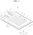
- FIG. 1 shows a perspective view of a secondary battery according to an example embodiment
- FIG. 2 and FIG. 3 show partially cut-away views of a secondary battery shown in FIG. 1
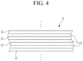
- FIG. 4 shows an enlarged view of an area A marked in FIG. 2 and FIG. 3 .
- the secondary battery 100 includes an electrode assembly 10, a case 20 for receiving the electrode assembly 10 and an electrolyte solution, and a swelling sensor 30 positioned on an outer side of the case 20.
- the electrode assembly 10 includes a positive electrode 12 and a negative electrode 13 with a separator 11 positioned therebetween.
- the positive electrode 12 may include a positive electrode current collector, and a positive electrode active material layer positioned on the positive electrode current collector.
- the negative electrode 13 may include a negative electrode current collector, and a negative active material layer positioned on the negative electrode current collector.
- the positive electrode current collector may include a metal foil such as aluminium, and the positive electrode active material layer may include an active material such as a transition metal oxide.
- the negative electrode current collector may include a metal foil such as copper or nickel, and the negative active material layer may include an active material such as graphite or carbon.
- the separator 11 may, e.g., include a complex film of a polyethylene and a polypropylene.
- the positive electrode 12, the negative electrode 13, and the separator 11 may respectively have a square sheet shape, and the positive electrode 12 and the negative electrode 13 may be alternately stacked with the separator 11 therebetween to thus configure the electrode assembly 10.
- FIG. 2 shows a stack-type electrode assembly.
- the positive electrode 12, the negative electrode 13, and the separator 11 may respectively have a band shape, and a stack of the positive electrode 12, the separator 11, the negative electrode 13, and the separator 11 may be wound and pressed to be flat, and may resultantly configure an electrode assembly in a jelly roll shape.
- FIG. 3 shows an electrode assembly 10 in a jelly roll shape.
- a positive uncoated region in which no positive electrode active material layer is positioned may be on the positive electrode current collector on a first end portion of the electrode assembly 10, and a negative uncoated region in which no negative active material layer is positioned may be on the negative electrode current collector.
- the secondary battery 100 may include a positive electrode terminal 14 attached to the positive uncoated region, and a negative terminal 15 attached to the negative uncoated region.
- the positive electrode terminal 14 may be spaced from the negative terminal 15 with a gap therebetween.
- the electrode assembly 10 may be received in the case 20 with the electrolyte solution.
- the electrolyte solution may, e.g., include a lithium salt such as LiPF 6 or LiBF 4 dissolved in an organic solvent.
- the case 20, which may be made of an exterior material, may receive the electrode assembly 10 and the electrolyte solution, and may close and seal them, and e.g., may be configured into a pouch-type case.
- the case 20 may include a first case 21 positioned on a first side (e.g., an upper side) of the electrode assembly 10, and a second case 22 positioned on an opposite side (e.g., a lower side) of the electrode assembly 10.
- the first case 21 and the second case 22 may commonly include bonding portions 211 and 221 combined along an edge by thermal fusion.
- Part of the positive electrode terminal 14 may be positioned inside the case 20, another part thereof may overlap the bonding portions 211 and 221, and the other part may be positioned outside the case 20.
- part of the negative terminal 15 may be positioned inside the case 20, another part may overlap the bonding portions 211 and 221, and the other part may be positioned outside the case 20.
- the positive electrode terminal 14 and the negative terminal 15 may be electrically connected to an external device.
- overlap or “overlapping” may indicate that a layer is either above or below another layer while being located at least partially in the same area with respect to a reference direction, e.g., a vertical direction. It will be understood that when a layer is referred to as "overlapping" another layer, it can be directly over or under that layer or one or more intervening layers may be present.
- the swelling sensor 30 may be attached to an outer side of the case 20 and may sense a swelling of the case 20.
- the swelling sensor 30 may be attached to an outer side of one of the first case 21 and the second case 22, or may be attached to the outer side of the first case 21 and the outer side of the second case 22.
- FIG. 1 to FIG. 3 show an example in which the swelling sensor 30 may be attached to the outer side of the first case 21.
- FIG. 5 shows a top plan view of an example embodiment of a swelling sensor in a secondary battery shown in FIG. 1
- FIG. 6 shows a partially enlarged view of FIG. 5
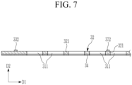
- FIG. 7 shows a cross-sectional view of a swelling sensor incised with respect to a line VII-VII of FIG. 5
- FIG. 8 shows a cross-sectional view of a swelling sensor incised with respect to a line VIII-VIII of FIG. 5 .
- the swelling sensor 30 includes a base film 32 providing a plurality of incised portions 31, and a conductive line 33 on the base film 32 passing among the incised portions 31, and may further include an adhesive layer 34 on a first side of the base film 32 facing toward the case 20.
- the base film 32 may be a flexible film made of a polymer material, and may be easily bent by an external force. A thickness of the base film 32 may be equal to or less than a thickness of the first case 21.
- the base film 32 may be attached to the outer side of the first case 21 by the adhesive layer 34, and may be transformed together with the first case 21 when the first case 21 swells.
- the incised portions 31 may represent a hole penetrating the base film 32, and may include a plurality of first incised portions 311 positioned in a first direction D1 of the base film 32, and a plurality of second incised portions 312 positioned in a second direction D2 traversing the first direction D1.
- the first direction D1 may be parallel to a width direction of the secondary battery 100
- the second direction D2 may be parallel to a length direction of the secondary battery 100.
- the respective first incised portions 311 may have a polygonal shape with more sides than a triangle, a circular shape, an oval shape, or may have a shape that is parallel to the first direction D1.
- the shape that is parallel to the first direction D1 may have forms such as a rectangular shape with a long side in parallel to the first direction D1, a rectangular shape with round corners, or a wavy shape with at least one curve.
- the respective second incised portions 312 may have a polygonal shape with more sides than a triangle, a circular shape, an oval shape, or may have a shape that is parallel to the second direction D2.
- the shape that is parallel to the second direction D2 may have forms such as a rectangular shape with a long side in parallel to the second direction D2, a rectangular shape with round corners, or a wavy shape with at least one curve.
- the first incised portions 311 may be positioned in a line at intervals in the first direction D1, and the second incised portions 312 may be positioned in a line at intervals in the second direction D2.
- FIG. 6 shows the rectangular first incised portion 311 and the rectangular second incised portion 312.
- the first incised portions 311 in parallel to the first direction D1 may be positioned to configure a plurality of rows (or horizontal lines) at intervals in the second direction D2, and the second incised portions 312 in parallel to the second direction D2 may be positioned to configure a plurality of columns (or perpendicular lines) at intervals in the first direction D1.
- the first incised portions 311 and the second incised portions 312 may substantially configure a lattice.
- the base film 32 may include a first bridge 321 positioned between two first incised portions 311 neighboring in the first direction D1.
- a width W1 of the first bridge 321 in the first direction D1 may be less than a length L1 of the long side of the first incised portion 311 in the first direction D1, and may be less than a length L2 of the short side of the first incised portion 311 in the second direction D2.
- the base film 32 may include a plurality of first bridges 321, and each one of the first incised portions 311 and the first bridges 321 may be alternately positioned in the first direction D1.
- the base film 32 may include a second bridge 322 positioned between the two second incised portions 312 neighboring in the second direction D2.
- a width W2 of the second bridge 322 in the second direction D2 may be less than a length L3 of the long side of the second incised portion 312 in the second direction D2, and may be less than a length L4 of the short side of the second incised portion 312 in the first direction D1.
- the base film 32 may include a plurality of second bridges 322, and each one of the second incised portions 312 and the second bridges 322 may be alternately positioned in the second direction D2.
- the conductive line 33 may pass among a plurality of incised portions 31 and may have a zigzag pattern on the base film 32.
- the swelling sensor 30 may further include a first terminal 35 and a second terminal 36 connected to the conductive line 33.
- the first terminal 35 and the second terminal 36 may be spaced from each other at the first edge of the base film 32, and may extend to the outside of the base film 32.
- the first terminal 35 and the second terminal 36 may be electrically connected to the external circuit 40.
- the conductive line 33 may be a metal film with a predetermined thickness and a predetermined width, and may be on a first side (an upper side in the drawing) of the base film 32 that is opposite the adhesive layer 34 according to a method such as a screen printing.
- a width W3 of the conductive line 33 may be less than the width W1 of the first bridge 321 in the first direction D1, and may be less than the width W2 of the second bridge 322 in the second direction D2.
- the conductive line 33 may have a zigzag pattern on the first bridge 321 and the second bridge 322.
- the conductive line 33 may include a pattern portion 331 passing over the first bridge 321 and the second bridge 322 and have a zigzag pattern, and a return portion 332 connected to the pattern portion 331 and along the first edge of the base film 32.
- the pattern portion 331 may be connected to the first terminal 35, and the return portion 332 may be connected to the second terminal 36.
- a conductive path connecting the first terminal 35, the pattern portion 331, the return portion 332, and the second terminal 36 may be provided.
- the pattern portion 331 may include a plurality of first straight line portions 371 in parallel to the first direction D1, and a plurality of second straight line portions 372 in parallel to the second direction D2.
- Each one of the second straight line portions 372 may be alternately connected to the first end portions (a left end portion in FIG. 5 ) of the first straight line portions 371 and the second end portions (a right end portion in FIG. 5 ) of the first straight line portions 371 and may configure a zigzag pattern together with the first straight line portions 371.
- the return portion 332 may be connected to an end portion of the pattern portion 331, and may be inside the first edge of the base film 32. In an implementation, the return portion 332 may be positioned nearer to the first edge of the base film 32 than the incised portion 31 and the pattern portion 331.
- the return portion 332 may include at least one straight line portion, and a portion of the return portion 332 near the second terminal 36 may pass above the first bridge 321 and the second bridge 322.
- FIG. 9 shows a cross-sectional view of a state of a swelling sensor when a secondary battery swells
- FIG. 10 shows a top plan view of a swelling sensor shown in FIG. 9
- the case 20 of the secondary battery 100 may stretch outward to generate a swelling phenomenon.
- the base film 32 attached to the first case 21 may also stretch outward to be transformed.
- the first bridge 321 and the second bridge 322 of the base film 32 may be weak in their structures so when the base film 32 is transformed, at least one of a plurality of first bridges 321 and at least one of a plurality of second bridges 322 may be damaged and disconnected. Therefore, part of the conductive line 33 passing over the first bridge 321 and the second bridge 322 may be damaged and disconnected.
- part of the conductive line 33 passing over the damaged first bridge 321 may also be damaged, and when at least one of the second bridges 322 is damaged, part of the conductive line 33 passing over the damaged second bridge 322 may be damaged.
- the first terminal 35 and the second terminal 36 of the swelling sensor 30 may be electrically connected to the external circuit 40, and the external circuit 40 may supply a predetermined current to the conductive line 33.
- the external circuit 40 may determine that a swelling is generated when the current flow is not sensed.
- the external circuit 40 may be electrically connected to a control unit of the external device using the secondary battery 100 as a power source, and it may output an alarm signal for notifying generation of swelling to the control unit of the external device when no current flow is sensed.
- the control unit of the external device may provide information for recommending replacement of secondary batteries to a user.
- FIG. 11 shows a top plan view of a secondary battery according to an example embodiment.
- the first terminal 35 and the second terminal 36 of the swelling sensor 30 may be connected to a battery management system (BMS) 50 of the secondary battery 101, and the conductive line 33 may function as a charging and discharging path when the secondary battery 101 is charged and discharged.
- BMS battery management system
- the secondary battery 101 and the external device may not be directly connected to each other, but may be electrically connected to each other through the conductive line 33 of the swelling sensor 30 therebetween. Therefore, when the secondary battery 101 is discharged, a discharging current may be provided to the external device by moving through the conductive line 33, and when the secondary battery 101 is charged, a charging current may be provided to the secondary battery 101 by moving through the conductive line 33.
- the secondary battery 101 may fail to be charged and discharged because of the incision of the conductive line 33.
- the secondary battery 101 may not be further used, and the case 20 of the secondary battery 101 may not further stretch outward and the swelling phenomenon may stop.
- the above-configured secondary batteries 100 and 101 may sense the swelling of the case 20 in an earlier stage by using the swelling sensor 30. As a result, the secondary batteries 100 and 101 may prevent the external device from being damage by the swelling, and may efficiently reduce the risks of fire by preventing the ignition phenomenon caused by the swelling.
- the electronic device including the secondary battery 100 may be damaged, and self-ignition may be generated because of the damage to the case 20. Therefore, methods for sensing the swelling of the case 20, preventing the case 20 from swelling, and thereby reducing damages and ignition of the electronic device are developed.
- the present disclosure has been made in an effort to provide a secondary battery 100 including a swelling sensor 30 for sensing a swelling phenomenon of a case 20 in an earlier stage.
- the secondary battery 100 may sense the swelling of the case 20 in an earlier stage by using the swelling sensor 30. As a result, the secondary battery 100 may prevent the external device from being damaged by the swelling, may prevent the ignition phenomenon caused by the swelling, and may efficiently reduce the risk of fire.
Landscapes
- Chemical & Material Sciences (AREA)
- Engineering & Computer Science (AREA)
- Chemical Kinetics & Catalysis (AREA)
- Electrochemistry (AREA)
- General Chemical & Material Sciences (AREA)
- Manufacturing & Machinery (AREA)
- General Physics & Mathematics (AREA)
- Physics & Mathematics (AREA)
- Microelectronics & Electronic Packaging (AREA)
- Analytical Chemistry (AREA)
- Materials Engineering (AREA)
- Connection Of Batteries Or Terminals (AREA)
- Sealing Battery Cases Or Jackets (AREA)
Abstract
A secondary battery comprising an electrode assembly including a positive electrode, a negative electrode, and a separator, a case accommodating and sealing the electrode assembly, and a swelling sensor on an outer side of the case, wherein the swelling sensor includes a base film on which a plurality of incised portions are disposed, and a conductive line on the base film passing among the plurality of incised portions.
Description
- The present disclosure relates to a secondary battery.
- An internal temperature of a secondary battery may increase when it is overcharged, and an electrolyte solution may decompose, generate gas, and increase an internal pressure when its internal temperature rises. In this case, a case of the secondary battery may stretch outward to generate a swelling phenomenon. The swelling phenomenon may also be generated by over-discharging, an internal short-circuit, an external short-circuit, and external heat in addition to overcharging.
- Embodiments are directed to a secondary battery. The secondary battery includes an electrode assembly having a positive electrode, a negative electrode, and a separator. The secondary battery also has a case accommodating and sealing the electrode assembly, and a swelling sensor on an outer side of the case. The swelling sensor includes a base film on which a plurality of incised portions are disposed, and a conductive line on the base film passing among the incised portions.
- Embodiments are also directed to a secondary battery. The secondary battery includes an electrode assembly having a positive electrode, a negative electrode, and a separator. The secondary battery also has a case accommodating and sealing the electrode assembly, and a swelling sensor attached to an outer side of the case. The swelling sensor includes a base film for providing a plurality of incised portions and including a plurality of bridges among the incised portions, and a conductive line on the bridges. When the case swells, the base film is transformed, at least one of the bridges may be damaged, and the conductive line may be incised.
- At least some of the above and other features of the invention are set out in the claims.
- Features will become apparent to those of skill in the art by describing in detail embodiments with reference to the attached drawings in which:
-
FIG. 1 shows a perspective view of a secondary battery according to an example embodiment. -
FIG. 2 andFIG. 3 show partially cut-away views of an example embodiment of a secondary battery shown inFIG. 1 . -
FIG. 4 shows an enlarged view of an area A marked inFIG. 2 andFIG. 3 . -
FIG. 5 shows a top plan view of a swelling sensor in an example embodiment of a secondary battery shown inFIG. 1 . -
FIG. 6 shows a partially enlarged view ofFIG. 5 . -
FIG. 7 shows a cross-sectional view of an example embodiment of a swelling sensor incised with respect to a line VII-VII ofFIG. 5 . -
FIG. 8 shows a cross-sectional view of an example embodiment of a swelling sensor incised with respect to a line VIII-VIII ofFIG. 5 . -
FIG. 9 shows a cross-sectional view of a state of an example embodiment of a swelling sensor when a secondary battery swells. -
FIG. 10 shows a top plan view of an example embodiment of a swelling sensor shown inFIG. 9 . -
FIG. 11 shows a top plan view of a secondary battery according to an example embodiment. - The present invention will be described more fully hereinafter with reference to the accompanying drawings, in which embodiments of the invention are shown. As those skilled in the art would realize, the described embodiments may be modified in various different ways, all without departing from the scope of the present invention.
-
FIG. 1 shows a perspective view of a secondary battery according to an example embodiment,FIG. 2 andFIG. 3 show partially cut-away views of a secondary battery shown inFIG. 1 , andFIG. 4 shows an enlarged view of an area A marked inFIG. 2 andFIG. 3 . - Referring to
FIG. 1 to FIG. 4 , thesecondary battery 100 includes anelectrode assembly 10, acase 20 for receiving theelectrode assembly 10 and an electrolyte solution, and aswelling sensor 30 positioned on an outer side of thecase 20. - The
electrode assembly 10 includes apositive electrode 12 and anegative electrode 13 with aseparator 11 positioned therebetween. Thepositive electrode 12 may include a positive electrode current collector, and a positive electrode active material layer positioned on the positive electrode current collector. Thenegative electrode 13 may include a negative electrode current collector, and a negative active material layer positioned on the negative electrode current collector. - The positive electrode current collector may include a metal foil such as aluminium, and the positive electrode active material layer may include an active material such as a transition metal oxide. The negative electrode current collector may include a metal foil such as copper or nickel, and the negative active material layer may include an active material such as graphite or carbon. The
separator 11 may, e.g., include a complex film of a polyethylene and a polypropylene. - The
positive electrode 12, thenegative electrode 13, and theseparator 11 may respectively have a square sheet shape, and thepositive electrode 12 and thenegative electrode 13 may be alternately stacked with theseparator 11 therebetween to thus configure theelectrode assembly 10.FIG. 2 shows a stack-type electrode assembly. - Meanwhile, the
positive electrode 12, thenegative electrode 13, and theseparator 11 may respectively have a band shape, and a stack of thepositive electrode 12, theseparator 11, thenegative electrode 13, and theseparator 11 may be wound and pressed to be flat, and may resultantly configure an electrode assembly in a jelly roll shape.FIG. 3 shows anelectrode assembly 10 in a jelly roll shape. - A positive uncoated region in which no positive electrode active material layer is positioned may be on the positive electrode current collector on a first end portion of the
electrode assembly 10, and a negative uncoated region in which no negative active material layer is positioned may be on the negative electrode current collector. Thesecondary battery 100 may include apositive electrode terminal 14 attached to the positive uncoated region, and anegative terminal 15 attached to the negative uncoated region. Thepositive electrode terminal 14 may be spaced from thenegative terminal 15 with a gap therebetween. - The
electrode assembly 10 may be received in thecase 20 with the electrolyte solution. The electrolyte solution may, e.g., include a lithium salt such as LiPF6 or LiBF4 dissolved in an organic solvent. Thecase 20, which may be made of an exterior material, may receive theelectrode assembly 10 and the electrolyte solution, and may close and seal them, and e.g., may be configured into a pouch-type case. - The
case 20 may include afirst case 21 positioned on a first side (e.g., an upper side) of theelectrode assembly 10, and asecond case 22 positioned on an opposite side (e.g., a lower side) of theelectrode assembly 10. Thefirst case 21 and thesecond case 22 may commonly include bondingportions - Part of the
positive electrode terminal 14 may be positioned inside thecase 20, another part thereof may overlap the bondingportions case 20. Like thepositive electrode terminal 14, part of thenegative terminal 15 may be positioned inside thecase 20, another part may overlap the bondingportions case 20. Thepositive electrode terminal 14 and thenegative terminal 15 may be electrically connected to an external device. The term "overlap" or "overlapping" may indicate that a layer is either above or below another layer while being located at least partially in the same area with respect to a reference direction, e.g., a vertical direction. It will be understood that when a layer is referred to as "overlapping" another layer, it can be directly over or under that layer or one or more intervening layers may be present. - The
swelling sensor 30 may be attached to an outer side of thecase 20 and may sense a swelling of thecase 20. Theswelling sensor 30 may be attached to an outer side of one of thefirst case 21 and thesecond case 22, or may be attached to the outer side of thefirst case 21 and the outer side of thesecond case 22.FIG. 1 to FIG. 3 show an example in which theswelling sensor 30 may be attached to the outer side of thefirst case 21. -
FIG. 5 shows a top plan view of an example embodiment of a swelling sensor in a secondary battery shown inFIG. 1 , andFIG. 6 shows a partially enlarged view ofFIG. 5 .FIG. 7 shows a cross-sectional view of a swelling sensor incised with respect to a line VII-VII ofFIG. 5 , andFIG. 8 shows a cross-sectional view of a swelling sensor incised with respect to a line VIII-VIII ofFIG. 5 . - Referring to
FIG. 5 to FIG. 8 , theswelling sensor 30 includes abase film 32 providing a plurality of incisedportions 31, and aconductive line 33 on thebase film 32 passing among the incisedportions 31, and may further include anadhesive layer 34 on a first side of thebase film 32 facing toward thecase 20. - The
base film 32 may be a flexible film made of a polymer material, and may be easily bent by an external force. A thickness of thebase film 32 may be equal to or less than a thickness of thefirst case 21. Thebase film 32 may be attached to the outer side of thefirst case 21 by theadhesive layer 34, and may be transformed together with thefirst case 21 when thefirst case 21 swells. - The incised
portions 31 may represent a hole penetrating thebase film 32, and may include a plurality of first incisedportions 311 positioned in a first direction D1 of thebase film 32, and a plurality of second incisedportions 312 positioned in a second direction D2 traversing the first direction D1. The first direction D1 may be parallel to a width direction of thesecondary battery 100, and the second direction D2 may be parallel to a length direction of thesecondary battery 100. - The respective first incised
portions 311 may have a polygonal shape with more sides than a triangle, a circular shape, an oval shape, or may have a shape that is parallel to the first direction D1. The shape that is parallel to the first direction D1 may have forms such as a rectangular shape with a long side in parallel to the first direction D1, a rectangular shape with round corners, or a wavy shape with at least one curve. - The respective second incised
portions 312 may have a polygonal shape with more sides than a triangle, a circular shape, an oval shape, or may have a shape that is parallel to the second direction D2. The shape that is parallel to the second direction D2 may have forms such as a rectangular shape with a long side in parallel to the second direction D2, a rectangular shape with round corners, or a wavy shape with at least one curve. - The first incised
portions 311 may be positioned in a line at intervals in the first direction D1, and the second incisedportions 312 may be positioned in a line at intervals in the second direction D2.FIG. 6 shows the rectangular first incisedportion 311 and the rectangular second incisedportion 312. - On the
base film 32, the first incisedportions 311 in parallel to the first direction D1 may be positioned to configure a plurality of rows (or horizontal lines) at intervals in the second direction D2, and the second incisedportions 312 in parallel to the second direction D2 may be positioned to configure a plurality of columns (or perpendicular lines) at intervals in the first direction D1. The first incisedportions 311 and the second incisedportions 312 may substantially configure a lattice. - The
base film 32 may include afirst bridge 321 positioned between two first incisedportions 311 neighboring in the first direction D1. A width W1 of thefirst bridge 321 in the first direction D1 may be less than a length L1 of the long side of the first incisedportion 311 in the first direction D1, and may be less than a length L2 of the short side of the first incisedportion 311 in the second direction D2. Thebase film 32 may include a plurality offirst bridges 321, and each one of the first incisedportions 311 and thefirst bridges 321 may be alternately positioned in the first direction D1. - The
base film 32 may include asecond bridge 322 positioned between the two second incisedportions 312 neighboring in the second direction D2. A width W2 of thesecond bridge 322 in the second direction D2 may be less than a length L3 of the long side of the second incisedportion 312 in the second direction D2, and may be less than a length L4 of the short side of the second incisedportion 312 in the first direction D1. Thebase film 32 may include a plurality ofsecond bridges 322, and each one of the second incisedportions 312 and thesecond bridges 322 may be alternately positioned in the second direction D2. - The
conductive line 33 may pass among a plurality of incisedportions 31 and may have a zigzag pattern on thebase film 32. The swellingsensor 30 may further include afirst terminal 35 and asecond terminal 36 connected to theconductive line 33. Thefirst terminal 35 and thesecond terminal 36 may be spaced from each other at the first edge of thebase film 32, and may extend to the outside of thebase film 32. Thefirst terminal 35 and thesecond terminal 36 may be electrically connected to theexternal circuit 40. - The
conductive line 33 may be a metal film with a predetermined thickness and a predetermined width, and may be on a first side (an upper side in the drawing) of thebase film 32 that is opposite theadhesive layer 34 according to a method such as a screen printing. A width W3 of theconductive line 33 may be less than the width W1 of thefirst bridge 321 in the first direction D1, and may be less than the width W2 of thesecond bridge 322 in the second direction D2. Theconductive line 33 may have a zigzag pattern on thefirst bridge 321 and thesecond bridge 322. - In an implementation, the
conductive line 33 may include apattern portion 331 passing over thefirst bridge 321 and thesecond bridge 322 and have a zigzag pattern, and areturn portion 332 connected to thepattern portion 331 and along the first edge of thebase film 32. Thepattern portion 331 may be connected to thefirst terminal 35, and thereturn portion 332 may be connected to thesecond terminal 36. A conductive path connecting thefirst terminal 35, thepattern portion 331, thereturn portion 332, and thesecond terminal 36 may be provided. - The
pattern portion 331 may include a plurality of firststraight line portions 371 in parallel to the first direction D1, and a plurality of secondstraight line portions 372 in parallel to the second direction D2. Each one of the secondstraight line portions 372 may be alternately connected to the first end portions (a left end portion inFIG. 5 ) of the firststraight line portions 371 and the second end portions (a right end portion inFIG. 5 ) of the firststraight line portions 371 and may configure a zigzag pattern together with the firststraight line portions 371. - The
return portion 332 may be connected to an end portion of thepattern portion 331, and may be inside the first edge of thebase film 32. In an implementation, thereturn portion 332 may be positioned nearer to the first edge of thebase film 32 than the incisedportion 31 and thepattern portion 331. Thereturn portion 332 may include at least one straight line portion, and a portion of thereturn portion 332 near thesecond terminal 36 may pass above thefirst bridge 321 and thesecond bridge 322. -
FIG. 9 shows a cross-sectional view of a state of a swelling sensor when a secondary battery swells, andFIG. 10 shows a top plan view of a swelling sensor shown inFIG. 9 . Referring toFIG. 1 ,FIG. 9 , andFIG. 10 , thecase 20 of thesecondary battery 100 may stretch outward to generate a swelling phenomenon. When thefirst case 21 stretches outward, thebase film 32 attached to thefirst case 21 may also stretch outward to be transformed. - The
first bridge 321 and thesecond bridge 322 of thebase film 32 may be weak in their structures so when thebase film 32 is transformed, at least one of a plurality offirst bridges 321 and at least one of a plurality ofsecond bridges 322 may be damaged and disconnected. Therefore, part of theconductive line 33 passing over thefirst bridge 321 and thesecond bridge 322 may be damaged and disconnected. - In an implementation, when at least one of the
first bridges 321 are damaged, part of theconductive line 33 passing over the damagedfirst bridge 321 may also be damaged, and when at least one of thesecond bridges 322 is damaged, part of theconductive line 33 passing over the damagedsecond bridge 322 may be damaged. - The
first terminal 35 and thesecond terminal 36 of the swellingsensor 30 may be electrically connected to theexternal circuit 40, and theexternal circuit 40 may supply a predetermined current to theconductive line 33. When part of theconductive line 33 is damaged by the damage of thefirst bridge 321 or thesecond bridge 322, a current flow may be blocked, and theexternal circuit 40 may determine that a swelling is generated when the current flow is not sensed. - The
external circuit 40 may be electrically connected to a control unit of the external device using thesecondary battery 100 as a power source, and it may output an alarm signal for notifying generation of swelling to the control unit of the external device when no current flow is sensed. The control unit of the external device may provide information for recommending replacement of secondary batteries to a user. -
FIG. 11 shows a top plan view of a secondary battery according to an example embodiment. Referring toFIG. 11 , thefirst terminal 35 and thesecond terminal 36 of the swellingsensor 30 may be connected to a battery management system (BMS) 50 of thesecondary battery 101, and theconductive line 33 may function as a charging and discharging path when thesecondary battery 101 is charged and discharged. - In an implementation, the
secondary battery 101 and the external device may not be directly connected to each other, but may be electrically connected to each other through theconductive line 33 of the swellingsensor 30 therebetween. Therefore, when thesecondary battery 101 is discharged, a discharging current may be provided to the external device by moving through theconductive line 33, and when thesecondary battery 101 is charged, a charging current may be provided to thesecondary battery 101 by moving through theconductive line 33. - When the
base film 32 is transformed by the swelling of thecase 20 and part of theconductive line 33 is damaged, thesecondary battery 101 may fail to be charged and discharged because of the incision of theconductive line 33. In an implementation, thesecondary battery 101 may not be further used, and thecase 20 of thesecondary battery 101 may not further stretch outward and the swelling phenomenon may stop. - The above-configured
secondary batteries case 20 in an earlier stage by using the swellingsensor 30. As a result, thesecondary batteries - By way of summation and review, when the swelling phenomenon of the
secondary battery 100 is neglected, the electronic device including thesecondary battery 100 may be damaged, and self-ignition may be generated because of the damage to thecase 20. Therefore, methods for sensing the swelling of thecase 20, preventing thecase 20 from swelling, and thereby reducing damages and ignition of the electronic device are developed. The present disclosure has been made in an effort to provide asecondary battery 100 including a swellingsensor 30 for sensing a swelling phenomenon of acase 20 in an earlier stage. - The
secondary battery 100 according to an embodiment may sense the swelling of thecase 20 in an earlier stage by using the swellingsensor 30. As a result, thesecondary battery 100 may prevent the external device from being damaged by the swelling, may prevent the ignition phenomenon caused by the swelling, and may efficiently reduce the risk of fire. - Example embodiments have been disclosed herein, and although specific terms are employed, they are used and are to be interpreted in a generic and descriptive sense only and not for purpose of limitation. In some instances, as would be apparent to one of ordinary skill in the art as of the filing of the present application, features, characteristics, and/or elements described in connection with a particular embodiment may be used singly or in combination with features, characteristics, and/or elements described in connection with other embodiments unless otherwise specifically indicated. Accordingly, it will be understood by those of skill in the art that various changes in form and details may be made without departing from the scope of the present invention as set forth in the following claims.
Claims (15)
- A secondary battery comprising:an electrode assembly including a positive electrode, a negative electrode, and a separator;a case accommodating and sealing the electrode assembly; anda swelling sensor on an outer side of the case,wherein the swelling sensor includesa base film on which a plurality of incised portions are disposed, anda conductive line on the base film passing among the plurality of incised portions.
- The secondary battery as claimed in claim 1, whereinthe swelling sensor further includes an adhesive layer on a first side of the base film facing the outer side of the case, andthe conductive line is on a second side of the base film that is opposite the adhesive layer.
- The secondary battery as claimed in claim 1 or claim 2, wherein each of the plurality of incised portions have a first plurality of incised portions in series in a first direction, and a second plurality of incised portions in series in a second direction traversing the first direction.
- The secondary battery as claimed in claim 3, wherein the conductive line passes among the first plurality of incised portions and among the second plurality of incised portions and are in a zigzag pattern.
- The secondary battery as claimed in claim 4, wherein:(i) the swelling sensor further includes:a first terminal and a second terminal connected to respective end portions of the conductive line, andan external circuit electrically connected to the first terminal and the second terminal and supplying a current to the conductive line; or(ii) the swelling sensor further includes a first terminal and a second terminal connected to respective end portions of the conductive line,the first terminal and the second terminal are connected to a battery management system, anda charging current and a discharge current move along the conductive line.
- The secondary battery as claimed in claim 1, whereinthe swelling sensor is attached to the outer side of the case,the base film includes a plurality of bridges among the incised portions, andthe conductive line is on the bridges, and when the case swells, the base film is transformed, at least one of the plurality of bridges is damaged, and the conductive line is incised.
- The secondary battery as claimed in claim 6, whereinthe plurality of incised portions have a first plurality of incised portions in a first direction and a second plurality of incised portions in a second direction traversing the first direction, andthe plurality of bridges have a first plurality of bridges among the first plurality of incised portions and a second plurality of bridges among the second plurality of incised portions.
- The secondary battery as claimed in claim 7, whereinthe first plurality of incised portions have a long side in parallel to the first direction and a short side in parallel to the second direction, andthe second plurality of incised portions have a long side in parallel to the second direction and a short side in parallel to the first direction.
- The secondary battery as claimed in claim 8, whereinwidths of the first plurality of bridges are less than a length of the long side of the first incised portion, andwidths of the second plurality of bridges are less than a length of the long side of the second incised portion.
- The secondary battery as claimed in claim 9, whereinwidths of the first plurality of bridges are less than a length of the short side of the first incised portion, andwidths of the second plurality of bridges are less than a length of the short side of the second incised portion, optionally whereinthe conductive line passes above the first plurality of bridges and the second plurality of bridges, anda width of the conductive line is less than the widths of the first plurality of bridges and the widths of the second plurality of bridges.
- The secondary battery as claimed in any one of claims 7 to 10, wherein the conductive line includes:a pattern portion passing above the first plurality of bridges and the second plurality of bridges and having a zigzag pattern, anda return portion connected to an end portion of the pattern portion and along a first edge of the base film.
- The secondary battery as claimed in claim 11, whereinthe swelling sensor further includes a first terminal and a second terminal with a gap therebetween on a second edge of the base film, andthe first terminal is connected to the pattern portion, and the second terminal is connected to the return portion.
- The secondary battery as claimed in claim 12, wherein:(i) the first terminal and the second terminal are connected to an external circuit, and
the external circuit supplies a current to the conductive line, and determines generation of swelling when a current flow is not sensed by a disconnection of the conductive line; or(ii) the first terminal and the second terminal are connected to a battery management system,a charging current and a discharging current move along the conductive line, anda charging and discharging function is lost when the conductive line is incised. - The secondary battery as claimed in any one of claims 1 to 13, whereinthe case includes a first case on a first side of the electrode assembly and a second case on a second side of the electrode assembly and bonded to the first case along an edge, andthe swelling sensor is on at least one of the outer side of the first case and the outer side of the second case.
- The secondary battery as claimed in any one of claims 1 to 14, wherein:(i) the separator includes a complex film of a polyethylene and a polypropylene;
and/or(ii) the positive electrode includes a positive electrode current collector, and a positive electrode active material layer positioned on the positive electrode current collector.
Applications Claiming Priority (1)
| Application Number | Priority Date | Filing Date | Title |
|---|---|---|---|
| KR1020220167898A KR102908017B1 (en) | 2022-12-05 | 2022-12-05 | Secondary battery with swelling detecting unit |
Publications (1)
| Publication Number | Publication Date |
|---|---|
| EP4383403A1 true EP4383403A1 (en) | 2024-06-12 |
Family
ID=86331757
Family Applications (1)
| Application Number | Title | Priority Date | Filing Date |
|---|---|---|---|
| EP23172945.0A Pending EP4383403A1 (en) | 2022-12-05 | 2023-05-11 | Secondary battery with swelling sensor |
Country Status (4)
| Country | Link |
|---|---|
| US (1) | US20240186600A1 (en) |
| EP (1) | EP4383403A1 (en) |
| KR (1) | KR102908017B1 (en) |
| CN (1) | CN118156652A (en) |
Cited By (1)
| Publication number | Priority date | Publication date | Assignee | Title |
|---|---|---|---|---|
| EP4730478A1 (en) * | 2024-10-15 | 2026-04-22 | Samsung Sdi Co., Ltd. | Secondary battery and battery module |
Citations (4)
| Publication number | Priority date | Publication date | Assignee | Title |
|---|---|---|---|---|
| KR20110037378A (en) * | 2009-10-06 | 2011-04-13 | 에너원코리아 주식회사 | Lithium-ion secondary battery pack and swelling detection means using a protection circuit [MCS] |
| WO2019059571A1 (en) * | 2017-09-22 | 2019-03-28 | Samsung Electronics Co., Ltd. | Method and electronic device for detecting battery swelling |
| US20200212417A1 (en) * | 2018-12-29 | 2020-07-02 | Lenovo (Beijing) Co., Ltd. | Battery, battery management method, and battery control method |
| CN112913068A (en) * | 2018-08-28 | 2021-06-04 | 美蓓亚三美株式会社 | Battery pack |
Family Cites Families (2)
| Publication number | Priority date | Publication date | Assignee | Title |
|---|---|---|---|---|
| KR100964175B1 (en) * | 2008-05-19 | 2010-06-17 | 주식회사 에스피엠탈로스 | Battery explosion prevention sensor and control method of battery charge / discharge circuit |
| KR20220049141A (en) * | 2020-10-14 | 2022-04-21 | 주식회사 엘지에너지솔루션 | Easy to check swollen cell case and battery cell comprising the same |
-
2022
- 2022-12-05 KR KR1020220167898A patent/KR102908017B1/en active Active
-
2023
- 2023-04-17 US US18/135,435 patent/US20240186600A1/en active Pending
- 2023-05-11 EP EP23172945.0A patent/EP4383403A1/en active Pending
- 2023-05-30 CN CN202310624651.7A patent/CN118156652A/en active Pending
Patent Citations (4)
| Publication number | Priority date | Publication date | Assignee | Title |
|---|---|---|---|---|
| KR20110037378A (en) * | 2009-10-06 | 2011-04-13 | 에너원코리아 주식회사 | Lithium-ion secondary battery pack and swelling detection means using a protection circuit [MCS] |
| WO2019059571A1 (en) * | 2017-09-22 | 2019-03-28 | Samsung Electronics Co., Ltd. | Method and electronic device for detecting battery swelling |
| CN112913068A (en) * | 2018-08-28 | 2021-06-04 | 美蓓亚三美株式会社 | Battery pack |
| US20200212417A1 (en) * | 2018-12-29 | 2020-07-02 | Lenovo (Beijing) Co., Ltd. | Battery, battery management method, and battery control method |
Cited By (1)
| Publication number | Priority date | Publication date | Assignee | Title |
|---|---|---|---|---|
| EP4730478A1 (en) * | 2024-10-15 | 2026-04-22 | Samsung Sdi Co., Ltd. | Secondary battery and battery module |
Also Published As
| Publication number | Publication date |
|---|---|
| KR20240083597A (en) | 2024-06-12 |
| US20240186600A1 (en) | 2024-06-06 |
| KR102908017B1 (en) | 2026-01-02 |
| CN118156652A (en) | 2024-06-07 |
Similar Documents
| Publication | Publication Date | Title |
|---|---|---|
| JP7041810B2 (en) | Battery module with a structure that breaks the connector using venting gas | |
| US8323824B2 (en) | Laminate type battery and battery module incorporating the laminate type battery | |
| US12494551B2 (en) | Battery pack having movable busbar assembly and secondary battery including the same | |
| EP2429018B1 (en) | Secondary battery | |
| EP1387419A2 (en) | Method for treating electrode tabs of crude cell for lithium secondary battery, and crude cell and lithium secondary battery according to the method | |
| EP2602840A2 (en) | Secondary battery pouch having improved stability, pouch-type secondary battery using same, and medium- or large-sized battery pack | |
| EP2339903B1 (en) | Lead plate and protection circuit module having the same | |
| TW201933651A (en) | Battery pack and method for manufactaring battery pack | |
| US10622615B2 (en) | Electrochemical device | |
| EP3716386B1 (en) | Secondary battery | |
| KR102264701B1 (en) | Rechargeable battery | |
| US10199616B2 (en) | Battery pack including cell frames coupled to each other | |
| US20110076544A1 (en) | Stack type battery | |
| US20170062795A1 (en) | Battery module | |
| US10312497B2 (en) | Rechargeable battery | |
| EP4383403A1 (en) | Secondary battery with swelling sensor | |
| US20150104674A1 (en) | Rechargeable battery | |
| US9761914B2 (en) | Battery pack | |
| KR200289707Y1 (en) | Crude cell for lithium secondary battery & lithium secondary battery therefrom | |
| US20250149725A1 (en) | Rechargeable battery | |
| EP4553964A1 (en) | Rechargeable battery | |
| KR20250138551A (en) | Electrode assembly and rechargeable battery with the same | |
| KR20230148001A (en) | Battery Cell Including Electrode Tab With Disconnection Prevention Function And A Battery Module Including It | |
| CN121863012A (en) | Protection circuit module, battery assembly, and method for manufacturing battery assembly | |
| KR20220042683A (en) | Battery cell including electrode tabs on which stress relief portions are formed |
Legal Events
| Date | Code | Title | Description |
|---|---|---|---|
| PUAI | Public reference made under article 153(3) epc to a published international application that has entered the european phase |
Free format text: ORIGINAL CODE: 0009012 |
|
| STAA | Information on the status of an ep patent application or granted ep patent |
Free format text: STATUS: REQUEST FOR EXAMINATION WAS MADE |
|
| 17P | Request for examination filed |
Effective date: 20230511 |
|
| AK | Designated contracting states |
Kind code of ref document: A1 Designated state(s): AL AT BE BG CH CY CZ DE DK EE ES FI FR GB GR HR HU IE IS IT LI LT LU LV MC ME MK MT NL NO PL PT RO RS SE SI SK SM TR |