EP4383053A1 - Input display device - Google Patents
Input display device Download PDFInfo
- Publication number
- EP4383053A1 EP4383053A1 EP23212696.1A EP23212696A EP4383053A1 EP 4383053 A1 EP4383053 A1 EP 4383053A1 EP 23212696 A EP23212696 A EP 23212696A EP 4383053 A1 EP4383053 A1 EP 4383053A1
- Authority
- EP
- European Patent Office
- Prior art keywords
- keyboard
- shaped
- finger
- touch
- protruding switch
- Prior art date
- Legal status (The legal status is an assumption and is not a legal conclusion. Google has not performed a legal analysis and makes no representation as to the accuracy of the status listed.)
- Granted
Links
Images


Classifications
-
- G—PHYSICS
- G06—COMPUTING OR CALCULATING; COUNTING
- G06F—ELECTRIC DIGITAL DATA PROCESSING
- G06F3/00—Input arrangements for transferring data to be processed into a form capable of being handled by the computer; Output arrangements for transferring data from processing unit to output unit, e.g. interface arrangements
- G06F3/01—Input arrangements or combined input and output arrangements for interaction between user and computer
- G06F3/03—Arrangements for converting the position or the displacement of a member into a coded form
- G06F3/041—Digitisers, e.g. for touch screens or touch pads, characterised by the transducing means
- G06F3/0416—Control or interface arrangements specially adapted for digitisers
- G06F3/0418—Control or interface arrangements specially adapted for digitisers for error correction or compensation, e.g. based on parallax, calibration or alignment
- G06F3/04186—Touch location disambiguation
-
- B—PERFORMING OPERATIONS; TRANSPORTING
- B60—VEHICLES IN GENERAL
- B60K—ARRANGEMENT OR MOUNTING OF PROPULSION UNITS OR OF TRANSMISSIONS IN VEHICLES; ARRANGEMENT OR MOUNTING OF PLURAL DIVERSE PRIME-MOVERS IN VEHICLES; AUXILIARY DRIVES FOR VEHICLES; INSTRUMENTATION OR DASHBOARDS FOR VEHICLES; ARRANGEMENTS IN CONNECTION WITH COOLING, AIR INTAKE, GAS EXHAUST OR FUEL SUPPLY OF PROPULSION UNITS IN VEHICLES
- B60K35/00—Instruments specially adapted for vehicles; Arrangement of instruments in or on vehicles
- B60K35/10—Input arrangements, i.e. from user to vehicle, associated with vehicle functions or specially adapted therefor
-
- B—PERFORMING OPERATIONS; TRANSPORTING
- B60—VEHICLES IN GENERAL
- B60K—ARRANGEMENT OR MOUNTING OF PROPULSION UNITS OR OF TRANSMISSIONS IN VEHICLES; ARRANGEMENT OR MOUNTING OF PLURAL DIVERSE PRIME-MOVERS IN VEHICLES; AUXILIARY DRIVES FOR VEHICLES; INSTRUMENTATION OR DASHBOARDS FOR VEHICLES; ARRANGEMENTS IN CONNECTION WITH COOLING, AIR INTAKE, GAS EXHAUST OR FUEL SUPPLY OF PROPULSION UNITS IN VEHICLES
- B60K35/00—Instruments specially adapted for vehicles; Arrangement of instruments in or on vehicles
- B60K35/20—Output arrangements, i.e. from vehicle to user, associated with vehicle functions or specially adapted therefor
- B60K35/21—Output arrangements, i.e. from vehicle to user, associated with vehicle functions or specially adapted therefor using visual output, e.g. blinking lights or matrix displays
- B60K35/22—Display screens
-
- G—PHYSICS
- G06—COMPUTING OR CALCULATING; COUNTING
- G06F—ELECTRIC DIGITAL DATA PROCESSING
- G06F1/00—Details not covered by groups G06F3/00 - G06F13/00 and G06F21/00
- G06F1/16—Constructional details or arrangements
- G06F1/1601—Constructional details related to the housing of computer displays, e.g. of CRT monitors, of flat displays
- G06F1/1603—Arrangements to protect the display from incident light, e.g. hoods
-
- G—PHYSICS
- G06—COMPUTING OR CALCULATING; COUNTING
- G06F—ELECTRIC DIGITAL DATA PROCESSING
- G06F3/00—Input arrangements for transferring data to be processed into a form capable of being handled by the computer; Output arrangements for transferring data from processing unit to output unit, e.g. interface arrangements
- G06F3/01—Input arrangements or combined input and output arrangements for interaction between user and computer
- G06F3/02—Input arrangements using manually operated switches, e.g. using keyboards or dials
-
- G—PHYSICS
- G06—COMPUTING OR CALCULATING; COUNTING
- G06F—ELECTRIC DIGITAL DATA PROCESSING
- G06F3/00—Input arrangements for transferring data to be processed into a form capable of being handled by the computer; Output arrangements for transferring data from processing unit to output unit, e.g. interface arrangements
- G06F3/01—Input arrangements or combined input and output arrangements for interaction between user and computer
- G06F3/03—Arrangements for converting the position or the displacement of a member into a coded form
- G06F3/041—Digitisers, e.g. for touch screens or touch pads, characterised by the transducing means
- G06F3/044—Digitisers, e.g. for touch screens or touch pads, characterised by the transducing means by capacitive means
-
- G—PHYSICS
- G06—COMPUTING OR CALCULATING; COUNTING
- G06F—ELECTRIC DIGITAL DATA PROCESSING
- G06F3/00—Input arrangements for transferring data to be processed into a form capable of being handled by the computer; Output arrangements for transferring data from processing unit to output unit, e.g. interface arrangements
- G06F3/01—Input arrangements or combined input and output arrangements for interaction between user and computer
- G06F3/048—Interaction techniques based on graphical user interfaces [GUI]
- G06F3/0487—Interaction techniques based on graphical user interfaces [GUI] using specific features provided by the input device, e.g. functions controlled by the rotation of a mouse with dual sensing arrangements, or of the nature of the input device, e.g. tap gestures based on pressure sensed by a digitiser
- G06F3/0488—Interaction techniques based on graphical user interfaces [GUI] using specific features provided by the input device, e.g. functions controlled by the rotation of a mouse with dual sensing arrangements, or of the nature of the input device, e.g. tap gestures based on pressure sensed by a digitiser using a touch-screen or digitiser, e.g. input of commands through traced gestures
- G06F3/04886—Interaction techniques based on graphical user interfaces [GUI] using specific features provided by the input device, e.g. functions controlled by the rotation of a mouse with dual sensing arrangements, or of the nature of the input device, e.g. tap gestures based on pressure sensed by a digitiser using a touch-screen or digitiser, e.g. input of commands through traced gestures by partitioning the display area of the touch-screen or the surface of the digitising tablet into independently controllable areas, e.g. virtual keyboards or menus
-
- B—PERFORMING OPERATIONS; TRANSPORTING
- B60—VEHICLES IN GENERAL
- B60K—ARRANGEMENT OR MOUNTING OF PROPULSION UNITS OR OF TRANSMISSIONS IN VEHICLES; ARRANGEMENT OR MOUNTING OF PLURAL DIVERSE PRIME-MOVERS IN VEHICLES; AUXILIARY DRIVES FOR VEHICLES; INSTRUMENTATION OR DASHBOARDS FOR VEHICLES; ARRANGEMENTS IN CONNECTION WITH COOLING, AIR INTAKE, GAS EXHAUST OR FUEL SUPPLY OF PROPULSION UNITS IN VEHICLES
- B60K2360/00—Indexing scheme associated with groups B60K35/00 or B60K37/00 relating to details of instruments or dashboards
- B60K2360/141—Activation of instrument input devices by approaching fingers or pens
-
- B—PERFORMING OPERATIONS; TRANSPORTING
- B60—VEHICLES IN GENERAL
- B60K—ARRANGEMENT OR MOUNTING OF PROPULSION UNITS OR OF TRANSMISSIONS IN VEHICLES; ARRANGEMENT OR MOUNTING OF PLURAL DIVERSE PRIME-MOVERS IN VEHICLES; AUXILIARY DRIVES FOR VEHICLES; INSTRUMENTATION OR DASHBOARDS FOR VEHICLES; ARRANGEMENTS IN CONNECTION WITH COOLING, AIR INTAKE, GAS EXHAUST OR FUEL SUPPLY OF PROPULSION UNITS IN VEHICLES
- B60K2360/00—Indexing scheme associated with groups B60K35/00 or B60K37/00 relating to details of instruments or dashboards
- B60K2360/143—Touch sensitive instrument input devices
- B60K2360/1438—Touch screens
-
- B—PERFORMING OPERATIONS; TRANSPORTING
- B60—VEHICLES IN GENERAL
- B60K—ARRANGEMENT OR MOUNTING OF PROPULSION UNITS OR OF TRANSMISSIONS IN VEHICLES; ARRANGEMENT OR MOUNTING OF PLURAL DIVERSE PRIME-MOVERS IN VEHICLES; AUXILIARY DRIVES FOR VEHICLES; INSTRUMENTATION OR DASHBOARDS FOR VEHICLES; ARRANGEMENTS IN CONNECTION WITH COOLING, AIR INTAKE, GAS EXHAUST OR FUEL SUPPLY OF PROPULSION UNITS IN VEHICLES
- B60K2360/00—Indexing scheme associated with groups B60K35/00 or B60K37/00 relating to details of instruments or dashboards
- B60K2360/143—Touch sensitive instrument input devices
- B60K2360/1446—Touch switches
-
- G—PHYSICS
- G06—COMPUTING OR CALCULATING; COUNTING
- G06F—ELECTRIC DIGITAL DATA PROCESSING
- G06F2203/00—Indexing scheme relating to G06F3/00 - G06F3/048
- G06F2203/041—Indexing scheme relating to G06F3/041 - G06F3/045
- G06F2203/04108—Touchless 2D- digitiser, i.e. digitiser detecting the X/Y position of the input means, finger or stylus, also when it does not touch, but is proximate to the digitiser's interaction surface without distance measurement in the Z direction
Definitions
- the present invention relates to an input display device having a human-machine interface function, and more particularly to an input display device including a three-dimensional operation unit.
- An input display device in which a protrusion is provided on a touch panel disposed to be superimposed on a display, and an image such as an operation icon is displayed at a position overlapping the protrusion (for example, JP 2020-190832 A ). The user performs an input by performing a touch operation on the protrusion.
- a user interface (hereinafter, referred to as a three-dimensional UI) in which a cover glass has an uneven shape so that a touch position is tactilely recognized and the touch position can be understood without gazing.
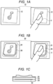
- Fig. 1A is an operation example of a conventional flat touch panel, and a user U visually recognizes an operation icon 12 displayed on a display 10 and performs an input by performing a touch operation on the position of the operation icon 12 (note in the example of Figure).
- Fig. 1B is an operation example of a touch panel having a three-dimensional UI
- Fig. 1C is a schematic cross-sectional view of the three-dimensional UI.
- a transparent cover lens 26 having an uneven shape is attached on a touch panel 24 including a capacitive sensor, and a display 20 displays an operation icon 22 at a position overlapping the cover lens 26.
- the user U performs input by touching the cover lens 26 with a finger.
- a highly sensitive electrostatic sensor capable of detecting the electrostatic capacitance (distance) of the finger even when the finger is away from the sensor is used for the touch detection, and the presence or absence of the touch can be determined even from on the thick cover lens 26. This makes it possible to reduce touch mistakes (operation error) under a situation where it is difficult to gaze at the in-vehicle display during driving.
- a keyboard-shaped or protruding switch 30 protruding in the horizontal direction from the display.
- the keyboard-shaped/protruding switch 30 has an operation face 32 extending laterally from a touch panel 40.
- a method of operating such a keyboard-shaped/protruding switch 30 is different from a method of operating a normal flat-shaped switch.
- a finger U is touched or pushed in the screen direction with respect to the flat operation face 42 on the touch panel 40, but in the keyboard-shaped/protruding switch, as illustrated in Fig. 2D , a touch operation is performed by placing the finger U on an operation face 44 protruding laterally from the touch panel 40.
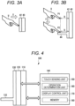
- Fig. 3A is a schematic cross section of a flat-shaped switch, and a flat cover glass 42 is attached on the touch panel 40.
- the user moves the finger U in the X direction and brings the finger U close to the cover glass 42 to perform a touch operation. For this reason, the distance from the sensor of the touch panel 40 to the finger U greatly changes, and the difference in value of the electrostatic capacitance measured at the time of touch/non-touch increases, and thus, it is easy to determine the threshold value of the presence or absence of the touch operation.
- An object of the present invention is to provide an input display device capable of accurately sensing the presence or absence of a touch operation on a keyboard-shaped/protruding switch.
- the invention relates to an input display device according to the appended claims. Embodiments are disclosed in the dependent claims.
- An input display device includes a display configured to display an image, and a capacitive touch panel mounted on the display, a keyboard-shaped/protruding switch provided on the touch panel, a sensing unit configured to sense a position of an operation target when the operation target approaches the touch panel, and a determination unit configured to determine presence or absence of a touch operation on the keyboard-shaped/protruding switch based on a variation in positions of the operation target sensed by the sensing unit.
- the determination unit determines whether a variation in sensed positions of the operation target is large, determines that a touch operation on the keyboard-shaped/protruding switch is not performed when the variation is large, and determines that a touch operation on the keyboard-shaped/protruding switch is performed when the variation is small. In an embodiment, the determination unit compares a variation in sensed positions of the operation target with a threshold value, determines that a touch operation on the keyboard-shaped/protruding switch is not performed when the variation is equal to or greater than the threshold value, and determines that a touch operation on the keyboard-shaped/protruding switch is performed when the variation is less than the threshold value.
- the determination unit acquires a certain number of sensed positions of the operation target, and calculates a variation in positions of the operation target from the certain number of the acquired positions of the operation target.
- the input display device further includes a cover glass on the touch panel, wherein the cover glass includes at least one keyboard-shaped/protruding switch, and wherein the keyboard-shaped/protruding switch includes a front face extending laterally from a front face of the touch panel.
- the display is an in-vehicle display.
- the determination accuracy of the touch operation on the keyboard-shaped/protruding switch can be improved, and erroneous determination can be suppressed.
- An input display device provides an interface between a person and a machine.
- the input display device of the present invention is not particularly limited, but is applied to, for example, an electronic device equipped with a display with a touch panel.
- the electronic device equipped with the display with a touch panel is, for example, an in-vehicle device having a navigation function, an audio visual function, a television function, and the like.
- FIG. 4 is a block diagram illustrating a configuration of an input display device according to an embodiment of the present invention.
- An input display device 100 of the present embodiment includes a display 110 configured to display an image and a video, a touch panel 120 including a capacitive sensor mounted on the display 110, a cover glass 130 attached to a front face of the touch panel 120 and including a keyboard-shaped/protruding switch 132 as a three-dimensional UI, and a controller 140 configured to control image display on the display 110, touch sensing on the touch panel 120, and the like.
- the display 110 is not particularly limited, but includes, for example, a liquid crystal panel or an organic EL panel, and displays image data provided from the controller 140.
- an operation icon representing an input operation may be displayed at a corresponding position of the keyboard-shaped/protruding switch 132.
- the touch panel 120 includes, for example, a plurality of sensors (sensing units) formed at positions where a plurality of X-side and Y-side electrode lines intersect, and the sensor senses an electrostatic capacitance when a user's finger, hand, or the like approaches or comes into contact with the cover glass 130 or the keyboard-shaped/protruding switch 132.
- the touch panel 120 is mounted on the display 110 and provides an input interface for the user to make an input to an icon or the like displayed on the display 110.
- the cover glass 130 is attached to the front face of the touch panel 120.
- the cover glass 130 may be part of the touch panel 120, or may be prepared separately from the touch panel 120.
- One or more keyboard-shaped/protruding switches 132 are formed on the cover glass 130 as a three-dimensional UI.
- the keyboard-shaped/protruding switch 132 has a keyboard-shaped or protruding shape, and the protruding shape includes at least a front face extending laterally from the cover glass 130, that is, a front face extending in a direction away from the touch panel 120. This front face has a size that allows at least a user's finger to be placed thereon.
- the shape, size, thickness, material, and the like of the keyboard-shaped/protruding switch 132 are not particularly limited, but include, for example, the operation face 32 extending laterally from the front face of the touch panel 40 as illustrated in Figs. 2A and 2B .
- the operation face 32 is not necessarily transparent, and characters, symbols, figures, and the like representing the content of the input operation may be drawn on the operation face. Further, the operation face 32 is not necessarily flat, and may include some irregularities, be linearly inclined, or be curved.
- the keyboard-shaped/protruding switch 132 may be formed integrally with the cover glass 130 or may be separate from the cover glass 130.
- the side face of the rectangular keyboard-shaped/protruding switch 132 may be attached to the cover glass 130 with a double-sided adhesive or the like.
- the keyboard-shaped/protruding switch 132 can be made of a material different from the cover glass 130, and is made of, for example, acrylic, polycarbonate, or the like.
- the coordinate position of the keyboard-shaped/protruding switch 132 on the touch panel 120 is registered in the memory of the controller 140, and when a finger approaching the touch panel 120 is sensed, the controller 140 determines whether the finger is a touch operation of the keyboard-shaped/protruding switch 132. Furthermore, the controller 140 can display an icon representing an input operation in the vicinity of the keyboard-shaped/protruding switch 132 via the display 110. The user visually recognizes an icon drawn on the operation face of the keyboard-shaped/protruding switch 132 or an icon displayed on the display 110, and performs an input operation by touching the keyboard-shaped/protruding switch 132.
- the controller 140 includes hardware and/or software resources, and performs overall processing of the input display device using, for example, an arithmetic processing unit, a microcontroller including a ROM/RAM, or the like. For example, the controller performs display processing of the display 110, touch sensing or operation determination (sense touch position and finger distance, and determine whether the touch operation is performed) from an output value of the touch panel 120, and processing of video display/video switching according to the touch sensing or operation determination.
- touch sensing or operation determination sense touch position and finger distance, and determine whether the touch operation is performed
- controller 140 includes a touch sensing unit 150, an operation determination unit 160, a display control unit 170, and a memory 180.
- the touch sensing unit 150 drives the plurality of electrode lines on the X side and/or the Y side of the touch panel 120, measures the electrostatic capacitance of each sensing unit (sensor) of the driven electrode lines, senses the touch position based on the measurement result, and provides the sensing result to the operation determination unit 160.
- the operation determination unit 160 determines the presence or absence of a touch operation on the touch panel 120 or a touch operation on the keyboard-shaped/protruding switch 132 based on the measurement result of the touch sensing unit 150.
- the touch mentioned here includes not only contact of the user's finger with the cover glass 130 and the keyboard-shaped/protruding switch 132 but also approach of the finger to the cover glass 130 and the keyboard-shaped/protruding switch 132.
- the operation determination unit 160 determines the presence or absence of a touch operation based on a change in electrostatic capacitance of a corresponding sensing unit (sensor), and similarly, when the user's finger contacts or approaches the keyboard-shaped/protruding switch 132, the operation determination unit determines the presence or absence of a touch operation on the keyboard-shaped/protruding switch 132 based on a change in electrostatic capacitance of a corresponding sensing unit (sensor).
- the display control unit 170 displays an image and a video on the display 110, and displays an icon at a corresponding position of the keyboard-shaped/protruding switch 132 as necessary. When no icon is drawn on the operation face of the keyboard-shaped/protruding switch 132, an icon representing the operation content of the keyboard-shaped/protruding switch 132 can be displayed on the display 110. In addition, the display control unit 170 switches an image to be displayed on the display 110 to another image in response to the operation determination unit 160 determining that a touch operation has been performed.
- the memory 180 stores information about coordinates, a size, and the like of the keyboard-shaped/protruding switch 132, coordinates of a touch position (finger position) sensed by the touch sensing unit 150, and the like.
- the memory 180 may store image data such as an icon to be displayed in the vicinity of the keyboard-shaped/protruding switch 132.
- an algorithm is used to determine whether a finger is in a state of not touching the keyboard-shaped/protruding switch in the air or in a state of touching the keyboard-shaped/protruding switch based on an amount of shake or variation in sensed finger positions.
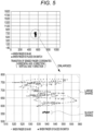
- Fig. 5 is a graph of a finger position (x, y coordinates) sensed when the finger is brought close to the keyboard-shaped/protruding switch, and the lower graph is an enlarged view of the sensed finger position.
- • represents a finger position when the finger is in the air, that is, a finger position when the finger U is not in contact with the keyboard-shaped/protruding switch 44 at the position P1 in Fig. 3B
- ⁇ represents a finger position when the finger U is placed on the front face of the keyboard-shaped/protruding switch 132, that is, a finger position when the finger U is in contact with the operation face of the keyboard-shaped/protruding switch 44 at the position P2 in Fig. 3B .
- the sensing algorithm of the present embodiment determines that there is a touch operation on the keyboard-shaped/protruding switch in a case where the amount of shake is small, and determines that there is no touch operation on the keyboard-shaped/protruding switch in a case where the amount of shake is large, based on the amount of shake (variation) of the sensed finger position.
- the threshold value for determining the magnitude of the variation is determined based on the sensing accuracy of the sensor of the touch panel 120. For example, in a case where the variation is calculated by the variance, the threshold value is set by a method in which whether the variance is a certain value or more or a movement average of x and y coordinate positions is obtained, and when the value exceeds 1 ⁇ of the normal distribution, the shake is large (a finger is in the air), and when the value is within 1 ⁇ , the shake is small (a keyboard-shaped switch is touched). Note that the determination of the amount of shake (variation) is not limited to the above algorithm, and any method may be used as long as the difference in the amount of shake can be determined as illustrated in the graph.
- Fig. 6 illustrates an operation flow of the sensing algorithm of the present embodiment.
- the touch sensing unit 150 senses the finger distance based on the measured electrostatic capacitance (S100).
- the finger distance is a distance from the sensor of the touch panel 120 to the finger.
- the finger distance sensed by the touch sensing unit 150 is provided to the operation determination unit 160.
- the operation determination unit 160 determines whether the sensed finger distance is equal to or greater than a threshold value (S110), that is, determines that the finger approaches the touch panel 120 when the finger distance is equal to or less than the threshold value. When determining that the finger is approaching, the operation determination unit 160 starts to acquire the coordinates of the finger position (X, Y coordinates), and stores the coordinates of a certain number of finger positions in the memory 180 (S120). Although the number of finger positions to be acquired is any number, for example, coordinates of 10 consecutive finger positions are acquired. When the sensor senses an electrostatic capacitance at 60 fps (frames per second), coordinates of 10 consecutive finger positions are obtained during 0.1 seconds.
- the operation determination unit 160 calculates a variation in finger positions from the coordinates of a certain number of finger positions stored in the memory (S130).
- a method of calculating the variation is any method, and for example, dispersion, standard deviation, or the like can be used.
- the variation is calculated in each of the X coordinate and the Y coordinate of the finger position.
- the operation determination unit 160 determines whether the variation is large (S140). For example, when the variance is used for calculating the variation, it is determined whether the variation exceeds a threshold value, and when the standard deviation is used, it is determined whether the variation falls within 1 ⁇ . This determination is made on each of the X coordinate and the Y coordinate of the finger position, and it is determined that the variation in finger positions is large when the variation in both the X coordinate and the Y coordinate is equal to or larger than the threshold value.
- the presence or absence of the touch operation on the keyboard-shaped/protruding switch is determined by utilizing the event that the magnitude difference occurs in the amount of shake (variation) of the finger position sensed depending on whether the finger touches the keyboard-shaped/protruding switch. Therefore, the determination accuracy of the touch operation on the keyboard-shaped/protruding switch is improved, and erroneous determination can be suppressed.
- the present invention is not necessarily limited to the finger, and the present invention is also applied to a case where the user touches the touch panel (cover glass) with a hand or other members.
- the variance or the standard deviation is used for calculating the variation, but this is an example, and the variation may be calculated by another method.
Landscapes
- Engineering & Computer Science (AREA)
- Theoretical Computer Science (AREA)
- General Engineering & Computer Science (AREA)
- Human Computer Interaction (AREA)
- Physics & Mathematics (AREA)
- General Physics & Mathematics (AREA)
- Chemical & Material Sciences (AREA)
- Combustion & Propulsion (AREA)
- Transportation (AREA)
- Mechanical Engineering (AREA)
- Computer Hardware Design (AREA)
- Position Input By Displaying (AREA)
- Input From Keyboards Or The Like (AREA)
- Switches That Are Operated By Magnetic Or Electric Fields (AREA)
Abstract
Description
- The present invention relates to an input display device having a human-machine interface function, and more particularly to an input display device including a three-dimensional operation unit.
- An input display device is disclosed in which a protrusion is provided on a touch panel disposed to be superimposed on a display, and an image such as an operation icon is displayed at a position overlapping the protrusion (for example,
JP 2020-190832 A - In a display device that performs a capacitive touch operation, there has been proposed a user interface (hereinafter, referred to as a three-dimensional UI) in which a cover glass has an uneven shape so that a touch position is tactilely recognized and the touch position can be understood without gazing.
-
Fig. 1A is an operation example of a conventional flat touch panel, and a user U visually recognizes anoperation icon 12 displayed on adisplay 10 and performs an input by performing a touch operation on the position of the operation icon 12 (note in the example of Figure). -
Fig. 1B is an operation example of a touch panel having a three-dimensional UI, andFig. 1C is a schematic cross-sectional view of the three-dimensional UI. Atransparent cover lens 26 having an uneven shape is attached on a touch panel 24 including a capacitive sensor, and adisplay 20 displays anoperation icon 22 at a position overlapping thecover lens 26. The user U performs input by touching thecover lens 26 with a finger. A highly sensitive electrostatic sensor capable of detecting the electrostatic capacitance (distance) of the finger even when the finger is away from the sensor is used for the touch detection, and the presence or absence of the touch can be determined even from on thethick cover lens 26. This makes it possible to reduce touch mistakes (operation error) under a situation where it is difficult to gaze at the in-vehicle display during driving. - In the three-dimensional UI, in order to realize a shape imitating various physical switches (buttons, knobs, sliders, and the like) existing in the vehicle interior and operation sensing thereof by a touch panel, it is required to cope with various operation gestures.
- As one of the in-vehicle switches, as illustrated in
Figs. 2A and 2B , there is a keyboard-shaped orprotruding switch 30 protruding in the horizontal direction from the display. The keyboard-shaped/protruding switch 30 has anoperation face 32 extending laterally from atouch panel 40. A method of operating such a keyboard-shaped/protruding switch 30 is different from a method of operating a normal flat-shaped switch. In the flat-shaped switch, as illustrated inFig. 2C , a finger U is touched or pushed in the screen direction with respect to theflat operation face 42 on thetouch panel 40, but in the keyboard-shaped/protruding switch, as illustrated inFig. 2D , a touch operation is performed by placing the finger U on anoperation face 44 protruding laterally from thetouch panel 40. - A more specific operation method will be described with reference to
Figs. 3A and 3B. Fig. 3A is a schematic cross section of a flat-shaped switch, and aflat cover glass 42 is attached on thetouch panel 40. The user moves the finger U in the X direction and brings the finger U close to thecover glass 42 to perform a touch operation. For this reason, the distance from the sensor of thetouch panel 40 to the finger U greatly changes, and the difference in value of the electrostatic capacitance measured at the time of touch/non-touch increases, and thus, it is easy to determine the threshold value of the presence or absence of the touch operation. - On the other hand, in the keyboard-shaped/protruding switch, as illustrated in
Fig. 3B , thecover glass 42 is attached onto thetouch panel 40, and thecover glass 42 has aprotrusion 44 protruding in a direction away from thetouch panel 40. - When the user performs a touch operation on the
protrusion 44, the user moves the finger U in the Y direction from a position P1 away from thetouch panel 40 by a distance D, and places the finger U on the front face of theprotrusion 44 at a position P2. While the finger U is at the distance D from thetouch panel 40 at the position P1, since the finger U floats in the air without contacting thecover glass 42, the electrostatic capacitance measured by the sensor is small, and the touch operation of the finger U is not sensed. While the finger U is at the distance D from thetouch panel 40 at the position P2, since the finger U comes into contact with the front face of theprotrusion 44, the electrostatic capacitance measured by the center increases, and the touch operation of the finger U is sensed. - However, when the finger U is placed on the front face of the
protrusion 44, since the finger U is away from thetouch panel 40 by the distance D, the difference between the electrostatic capacitance at the time of non-contact at the position P1 and the electrostatic capacitance at the time of contact at the position P2 does not greatly change, and it is difficult to determine the presence or absence of the touch operation. For this reason, in the touch operation on the keyboard-shaped/protruding switch, a sensing method capable of accurately determining the presence or absence of the touch operation is required. - An object of the present invention is to provide an input display device capable of accurately sensing the presence or absence of a touch operation on a keyboard-shaped/protruding switch.
- The invention relates to an input display device according to the appended claims. Embodiments are disclosed in the dependent claims.
- An input display device according to an aspect of the present invention includes a display configured to display an image, and a capacitive touch panel mounted on the display, a keyboard-shaped/protruding switch provided on the touch panel, a sensing unit configured to sense a position of an operation target when the operation target approaches the touch panel, and a determination unit configured to determine presence or absence of a touch operation on the keyboard-shaped/protruding switch based on a variation in positions of the operation target sensed by the sensing unit.
- In an embodiment, the determination unit determines whether a variation in sensed positions of the operation target is large, determines that a touch operation on the keyboard-shaped/protruding switch is not performed when the variation is large, and determines that a touch operation on the keyboard-shaped/protruding switch is performed when the variation is small. In an embodiment, the determination unit compares a variation in sensed positions of the operation target with a threshold value, determines that a touch operation on the keyboard-shaped/protruding switch is not performed when the variation is equal to or greater than the threshold value, and determines that a touch operation on the keyboard-shaped/protruding switch is performed when the variation is less than the threshold value. In an embodiment, the determination unit acquires a certain number of sensed positions of the operation target, and calculates a variation in positions of the operation target from the certain number of the acquired positions of the operation target. In an embodiment, the input display device further includes a cover glass on the touch panel, wherein the cover glass includes at least one keyboard-shaped/protruding switch, and wherein the keyboard-shaped/protruding switch includes a front face extending laterally from a front face of the touch panel. In an embodiment, the display is an in-vehicle display.
- According to aspects of the present invention, since the presence or absence of the touch operation on the keyboard-shaped/protruding switch is determined based on the variation in sensed positions of the operation target, the determination accuracy of the touch operation on the keyboard-shaped/protruding switch can be improved, and erroneous determination can be suppressed.
-
Fig. 1A illustrates an operation example of a flat touch panel,Fig. 1B illustrates an operation example of a touch panel of a three-dimensional UI, andFig. 1C is a schematic cross-sectional view of the three-dimensional UI. -
Figs. 2A and 2B are perspective views illustrating a configuration example of a keyboard-shaped/protruding switch,Fig. 2C is an operation example of a flat-shaped switch, andFig. 2D is a view illustrating an operation example of a keyboard-shaped/protruding switch. -
Fig. 3A is a diagram illustrating a specific operation example of a flat-shaped switch, andFig. 3B is a diagram illustrating a specific operation example of a keyboard-shaped/protruding switch. -
Fig. 4 is a block diagram illustrating a configuration of an input display device according to an embodiment of the present invention. -
Fig. 5 is an exemplary graph illustrating transition of a finger position (x, y coordinates) sensed when the finger is in the air and when the finger is placed on the keyboard-shaped/protruding switch. -
Fig. 6 is an operation flow illustrating a sensing algorithm of a touch operation of a keyboard-shaped/protruding switch according to an embodiment of the present invention. - An input display device according to aspects of the present invention provides an interface between a person and a machine. The input display device of the present invention is not particularly limited, but is applied to, for example, an electronic device equipped with a display with a touch panel. The electronic device equipped with the display with a touch panel is, for example, an in-vehicle device having a navigation function, an audio visual function, a television function, and the like.
- Next, embodiments of the present invention will be described in detail with reference to the drawings.
Fig. 4 is a block diagram illustrating a configuration of an input display device according to an embodiment of the present invention. Aninput display device 100 of the present embodiment includes adisplay 110 configured to display an image and a video, atouch panel 120 including a capacitive sensor mounted on thedisplay 110, acover glass 130 attached to a front face of thetouch panel 120 and including a keyboard-shaped/protruding switch 132 as a three-dimensional UI, and acontroller 140 configured to control image display on thedisplay 110, touch sensing on thetouch panel 120, and the like. - The
display 110 is not particularly limited, but includes, for example, a liquid crystal panel or an organic EL panel, and displays image data provided from thecontroller 140. For example, an operation icon representing an input operation may be displayed at a corresponding position of the keyboard-shaped/protrudingswitch 132. - The
touch panel 120 includes, for example, a plurality of sensors (sensing units) formed at positions where a plurality of X-side and Y-side electrode lines intersect, and the sensor senses an electrostatic capacitance when a user's finger, hand, or the like approaches or comes into contact with thecover glass 130 or the keyboard-shaped/protrudingswitch 132. Thetouch panel 120 is mounted on thedisplay 110 and provides an input interface for the user to make an input to an icon or the like displayed on thedisplay 110. - The
cover glass 130 is attached to the front face of thetouch panel 120. Thecover glass 130 may be part of thetouch panel 120, or may be prepared separately from thetouch panel 120. - One or more keyboard-shaped/protruding
switches 132 are formed on thecover glass 130 as a three-dimensional UI. The keyboard-shaped/protrudingswitch 132 has a keyboard-shaped or protruding shape, and the protruding shape includes at least a front face extending laterally from thecover glass 130, that is, a front face extending in a direction away from thetouch panel 120. This front face has a size that allows at least a user's finger to be placed thereon. - The shape, size, thickness, material, and the like of the keyboard-shaped/protruding
switch 132 are not particularly limited, but include, for example, theoperation face 32 extending laterally from the front face of thetouch panel 40 as illustrated inFigs. 2A and 2B . The operation face 32 is not necessarily transparent, and characters, symbols, figures, and the like representing the content of the input operation may be drawn on the operation face. Further, theoperation face 32 is not necessarily flat, and may include some irregularities, be linearly inclined, or be curved. - Further, the keyboard-shaped/protruding
switch 132 may be formed integrally with thecover glass 130 or may be separate from thecover glass 130. For example, the side face of the rectangular keyboard-shaped/protrudingswitch 132 may be attached to thecover glass 130 with a double-sided adhesive or the like. In this case, the keyboard-shaped/protrudingswitch 132 can be made of a material different from thecover glass 130, and is made of, for example, acrylic, polycarbonate, or the like. - The coordinate position of the keyboard-shaped/protruding
switch 132 on thetouch panel 120 is registered in the memory of thecontroller 140, and when a finger approaching thetouch panel 120 is sensed, thecontroller 140 determines whether the finger is a touch operation of the keyboard-shaped/protrudingswitch 132. Furthermore, thecontroller 140 can display an icon representing an input operation in the vicinity of the keyboard-shaped/protrudingswitch 132 via thedisplay 110. The user visually recognizes an icon drawn on the operation face of the keyboard-shaped/protrudingswitch 132 or an icon displayed on thedisplay 110, and performs an input operation by touching the keyboard-shaped/protrudingswitch 132. - The
controller 140 includes hardware and/or software resources, and performs overall processing of the input display device using, for example, an arithmetic processing unit, a microcontroller including a ROM/RAM, or the like. For example, the controller performs display processing of thedisplay 110, touch sensing or operation determination (sense touch position and finger distance, and determine whether the touch operation is performed) from an output value of thetouch panel 120, and processing of video display/video switching according to the touch sensing or operation determination. - In an aspect, as illustrated in
Fig. 4 ,controller 140 includes atouch sensing unit 150, anoperation determination unit 160, adisplay control unit 170, and amemory 180. Thetouch sensing unit 150 drives the plurality of electrode lines on the X side and/or the Y side of thetouch panel 120, measures the electrostatic capacitance of each sensing unit (sensor) of the driven electrode lines, senses the touch position based on the measurement result, and provides the sensing result to theoperation determination unit 160. - The
operation determination unit 160 determines the presence or absence of a touch operation on thetouch panel 120 or a touch operation on the keyboard-shaped/protrudingswitch 132 based on the measurement result of thetouch sensing unit 150. The touch mentioned here includes not only contact of the user's finger with thecover glass 130 and the keyboard-shaped/protrudingswitch 132 but also approach of the finger to thecover glass 130 and the keyboard-shaped/protrudingswitch 132. For example, when the user's finger contacts or approaches the flat front face of thecover glass 130, theoperation determination unit 160 determines the presence or absence of a touch operation based on a change in electrostatic capacitance of a corresponding sensing unit (sensor), and similarly, when the user's finger contacts or approaches the keyboard-shaped/protrudingswitch 132, the operation determination unit determines the presence or absence of a touch operation on the keyboard-shaped/protrudingswitch 132 based on a change in electrostatic capacitance of a corresponding sensing unit (sensor). - The
display control unit 170 displays an image and a video on thedisplay 110, and displays an icon at a corresponding position of the keyboard-shaped/protrudingswitch 132 as necessary. When no icon is drawn on the operation face of the keyboard-shaped/protrudingswitch 132, an icon representing the operation content of the keyboard-shaped/protrudingswitch 132 can be displayed on thedisplay 110. In addition, thedisplay control unit 170 switches an image to be displayed on thedisplay 110 to another image in response to theoperation determination unit 160 determining that a touch operation has been performed. - The
memory 180 stores information about coordinates, a size, and the like of the keyboard-shaped/protrudingswitch 132, coordinates of a touch position (finger position) sensed by thetouch sensing unit 150, and the like. In addition, thememory 180 may store image data such as an icon to be displayed in the vicinity of the keyboard-shaped/protrudingswitch 132. - Next, a sensing operation of a touch operation of the keyboard-shaped/protruding switch according to the present embodiment will be described. In the present embodiment, an algorithm is used to determine whether a finger is in a state of not touching the keyboard-shaped/protruding switch in the air or in a state of touching the keyboard-shaped/protruding switch based on an amount of shake or variation in sensed finger positions.
-
Fig. 5 is a graph of a finger position (x, y coordinates) sensed when the finger is brought close to the keyboard-shaped/protruding switch, and the lower graph is an enlarged view of the sensed finger position. • represents a finger position when the finger is in the air, that is, a finger position when the finger U is not in contact with the keyboard-shaped/protrudingswitch 44 at the position P1 inFig. 3B , and ▲ represents a finger position when the finger U is placed on the front face of the keyboard-shaped/protrudingswitch 132, that is, a finger position when the finger U is in contact with the operation face of the keyboard-shaped/protrudingswitch 44 at the position P2 inFig. 3B . - As is clear from the graph, it can be seen that the amount of shake (variation) of the finger position sensed when the finger U touches the front face of the keyboard-shaped/protruding switch is small, but the amount of shake (variation) of the finger position sensed when the finger is in the air is large. That is, depending on whether the finger touches the keyboard-shaped/protruding switch, a magnitude difference occurs in an amount of shake (variation) of the sensed finger position. The sensing algorithm of the present embodiment determines that there is a touch operation on the keyboard-shaped/protruding switch in a case where the amount of shake is small, and determines that there is no touch operation on the keyboard-shaped/protruding switch in a case where the amount of shake is large, based on the amount of shake (variation) of the sensed finger position.
- A specific example of the sensing algorithm is shown below.
- 1. The transition of a certain number of the finger positions sensed by the
touch sensing unit 150 is recorded. For example, coordinates of a certain number of sensed finger positions are stored in thememory 180. - 2. For the transition of the recorded finger position (coordinate position), for example, the variation in transition amounts of the finger position is calculated from variance, standard deviation, and the like.
- 3. When the variation is equal to or less than the threshold value, it is determined that the finger is placed on the keyboard-shaped/protruding switch. That is, it is determined that a touch operation on the keyboard-shaped/protruding switch has been performed.
- Here, the threshold value for determining the magnitude of the variation is determined based on the sensing accuracy of the sensor of the
touch panel 120. For example, in a case where the variation is calculated by the variance, the threshold value is set by a method in which whether the variance is a certain value or more or a movement average of x and y coordinate positions is obtained, and when the value exceeds 1σ of the normal distribution, the shake is large (a finger is in the air), and when the value is within 1σ, the shake is small (a keyboard-shaped switch is touched). Note that the determination of the amount of shake (variation) is not limited to the above algorithm, and any method may be used as long as the difference in the amount of shake can be determined as illustrated in the graph. -
Fig. 6 illustrates an operation flow of the sensing algorithm of the present embodiment. Thetouch sensing unit 150 senses the finger distance based on the measured electrostatic capacitance (S100). The finger distance is a distance from the sensor of thetouch panel 120 to the finger. The finger distance sensed by thetouch sensing unit 150 is provided to theoperation determination unit 160. - The
operation determination unit 160 determines whether the sensed finger distance is equal to or greater than a threshold value (S110), that is, determines that the finger approaches thetouch panel 120 when the finger distance is equal to or less than the threshold value. When determining that the finger is approaching, theoperation determination unit 160 starts to acquire the coordinates of the finger position (X, Y coordinates), and stores the coordinates of a certain number of finger positions in the memory 180 (S120). Although the number of finger positions to be acquired is any number, for example, coordinates of 10 consecutive finger positions are acquired. When the sensor senses an electrostatic capacitance at 60 fps (frames per second), coordinates of 10 consecutive finger positions are obtained during 0.1 seconds. - Next, the
operation determination unit 160 calculates a variation in finger positions from the coordinates of a certain number of finger positions stored in the memory (S130). A method of calculating the variation is any method, and for example, dispersion, standard deviation, or the like can be used. The variation is calculated in each of the X coordinate and the Y coordinate of the finger position. - Next, the
operation determination unit 160 determines whether the variation is large (S140). For example, when the variance is used for calculating the variation, it is determined whether the variation exceeds a threshold value, and when the standard deviation is used, it is determined whether the variation falls within 1σ. This determination is made on each of the X coordinate and the Y coordinate of the finger position, and it is determined that the variation in finger positions is large when the variation in both the X coordinate and the Y coordinate is equal to or larger than the threshold value. - When it is determined that the variation is large, it is determined that the finger does not touch the keyboard-shaped/protruding switch (the finger is in the air), and this routine is ended, and preparation for next finger sensing is performed. On the other hand, when it is determined that the variation is small, it is determined that the finger touches the keyboard-shaped/protruding switch located in the sensed finger coordinate area (S150). As a result, the
controller 140 determines that an input operation on the keyboard-shaped/protruding switch has been performed. - As described above, according to the present embodiment, in the keyboard-shaped/protruding switch, the presence or absence of the touch operation on the keyboard-shaped/protruding switch is determined by utilizing the event that the magnitude difference occurs in the amount of shake (variation) of the finger position sensed depending on whether the finger touches the keyboard-shaped/protruding switch. Therefore, the determination accuracy of the touch operation on the keyboard-shaped/protruding switch is improved, and erroneous determination can be suppressed.
- In the above embodiment, the example in which the user touches the touch panel (cover glass) with a finger is used, but the present invention is not necessarily limited to the finger, and the present invention is also applied to a case where the user touches the touch panel (cover glass) with a hand or other members. In the above embodiment, the variance or the standard deviation is used for calculating the variation, but this is an example, and the variation may be calculated by another method.
- Embodiments of the present invention have been described in detail above. However, the present invention is not limited to the specific embodiments, and thus various modifications and alterations can be made in the scope of the claims.
-
- 30, 44
- keyboard-shaped/protruding switch
- 100
- input display device
- 110
- display
- 120
- touch panel
- 130
- cover glass
- 132
- keyboard-shaped/protruding switch
- 140
- Controller
Claims (6)
- An input display device (100) comprising a display (110) configured to display an image, and a capacitive touch panel (120) mounted on the display (110),a keyboard-shaped/protruding switch (132) provided on the touch panel (120);a sensing unit (150) configured to sense a position of an operation target when the operation target approaches the touch panel (120); anda determination unit (160) configured to determine presence or absence of a touch operation on the keyboard-shaped/protruding switch (132) based on a variation in positions of the operation target sensed by the sensing unit (150).
- The input display device (100) according to claim 1, wherein the determination unit (160) is configured to determine whether a variation in sensed positions of the operation target is large, to determine that a touch operation on the keyboard-shaped/protruding switch (132) is not performed when the variation is large, and to determine that a touch operation on the keyboard-shaped/protruding switch (132) is performed when the variation is small.
- The input display device (100) according to claim 1 or 2, wherein the determination unit (160) is configured to compare a variation in sensed positions of the operation target with a threshold value, to determine that a touch operation on the keyboard-shaped/protruding switch (132) is not performed when the variation is equal to or greater than the threshold value, and to determine that a touch operation on the keyboard-shaped/protruding switch (132) is performed when the variation is less than the threshold value.
- The input display device (100) according to one of claims 1 - 3, wherein the determination unit (160) is configured to acquire a certain number of sensed positions of the operation target, and to calculate a variation in positions of the operation target from the certain number of the acquired positions of the operation target.
- The input display device (100) according to one of claims 1 - 4, further comprising:a cover glass (130) on the touch panel (120), wherein the cover glass (130) includes at least one keyboard-shaped/protruding switch (132), and whereinthe keyboard-shaped/protruding switch (132) includes a front face extending laterally from a front face of the touch panel (120).
- The input display device (100) according to one of claims 1 - 5, wherein the display (110) is an in-vehicle display.
Applications Claiming Priority (1)
| Application Number | Priority Date | Filing Date | Title |
|---|---|---|---|
| JP2022194647A JP2024081202A (en) | 2022-12-06 | 2022-12-06 | Input display device |
Publications (2)
| Publication Number | Publication Date |
|---|---|
| EP4383053A1 true EP4383053A1 (en) | 2024-06-12 |
| EP4383053B1 EP4383053B1 (en) | 2025-08-20 |
Family
ID=88978298
Family Applications (1)
| Application Number | Title | Priority Date | Filing Date |
|---|---|---|---|
| EP23212696.1A Active EP4383053B1 (en) | 2022-12-06 | 2023-11-28 | Input display device |
Country Status (4)
| Country | Link |
|---|---|
| US (1) | US12307051B2 (en) |
| EP (1) | EP4383053B1 (en) |
| JP (1) | JP2024081202A (en) |
| CN (1) | CN118151778A (en) |
Citations (4)
| Publication number | Priority date | Publication date | Assignee | Title |
|---|---|---|---|---|
| US20150169114A1 (en) * | 2010-08-27 | 2015-06-18 | Apple Inc. | Touch and hover sensor compensation |
| US20150277760A1 (en) * | 2012-11-05 | 2015-10-01 | Ntt Docomo, Inc. | Terminal device, screen display method, hover position correction method, and recording medium |
| JP2020190832A (en) | 2019-05-20 | 2020-11-26 | 株式会社デンソー | Input display device |
| WO2022090091A1 (en) * | 2020-10-26 | 2022-05-05 | Hap2U | Three-dimensional touch interface providing haptic feedback |
-
2022
- 2022-12-06 JP JP2022194647A patent/JP2024081202A/en active Pending
-
2023
- 2023-11-09 US US18/505,322 patent/US12307051B2/en active Active
- 2023-11-28 CN CN202311599666.9A patent/CN118151778A/en active Pending
- 2023-11-28 EP EP23212696.1A patent/EP4383053B1/en active Active
Patent Citations (5)
| Publication number | Priority date | Publication date | Assignee | Title |
|---|---|---|---|---|
| US20150169114A1 (en) * | 2010-08-27 | 2015-06-18 | Apple Inc. | Touch and hover sensor compensation |
| US20150277760A1 (en) * | 2012-11-05 | 2015-10-01 | Ntt Docomo, Inc. | Terminal device, screen display method, hover position correction method, and recording medium |
| JP2020190832A (en) | 2019-05-20 | 2020-11-26 | 株式会社デンソー | Input display device |
| WO2022090091A1 (en) * | 2020-10-26 | 2022-05-05 | Hap2U | Three-dimensional touch interface providing haptic feedback |
| US20230400924A1 (en) * | 2020-10-26 | 2023-12-14 | Hap2U | Three-dimensional touch interface providing haptic feedback |
Also Published As
| Publication number | Publication date |
|---|---|
| US20240184404A1 (en) | 2024-06-06 |
| EP4383053B1 (en) | 2025-08-20 |
| US12307051B2 (en) | 2025-05-20 |
| CN118151778A (en) | 2024-06-07 |
| JP2024081202A (en) | 2024-06-18 |
Similar Documents
| Publication | Publication Date | Title |
|---|---|---|
| US20080192024A1 (en) | Operator distinguishing device | |
| EP1126406A2 (en) | Touch panel input device | |
| US20060244733A1 (en) | Touch sensitive device and method using pre-touch information | |
| EP2508965B1 (en) | Touch-sensitive display apparatus and method for displaying object thereof | |
| EP4386529A1 (en) | Input display device | |
| JP2012099005A (en) | Input device, input method, and input program | |
| EP4383053A1 (en) | Input display device | |
| EP4354264A1 (en) | Input display device | |
| US12277280B2 (en) | Input display device | |
| JP2006350789A (en) | Display device with touch panel | |
| EP4354263B1 (en) | Input display device | |
| KR102246818B1 (en) | Capacitive input device and user input judging method using the same | |
| EP4546095A1 (en) | Input display device | |
| US20180292924A1 (en) | Input processing apparatus | |
| US12585368B2 (en) | Input display device | |
| JP7838110B2 (en) | Electrostatic coordinate input device, and operation determination method for electrostatic coordinate input device | |
| KR20260029595A (en) | Touch control method for display panel | |
| KR20260018220A (en) | Display panel with physical buttons and touch control method | |
| JP2022136389A (en) | Touch panel device and display device using the same | |
| JP2014130385A (en) | Touch input device |
Legal Events
| Date | Code | Title | Description |
|---|---|---|---|
| PUAI | Public reference made under article 153(3) epc to a published international application that has entered the european phase |
Free format text: ORIGINAL CODE: 0009012 |
|
| STAA | Information on the status of an ep patent application or granted ep patent |
Free format text: STATUS: THE APPLICATION HAS BEEN PUBLISHED |
|
| AK | Designated contracting states |
Kind code of ref document: A1 Designated state(s): AL AT BE BG CH CY CZ DE DK EE ES FI FR GB GR HR HU IE IS IT LI LT LU LV MC ME MK MT NL NO PL PT RO RS SE SI SK SM TR |
|
| STAA | Information on the status of an ep patent application or granted ep patent |
Free format text: STATUS: REQUEST FOR EXAMINATION WAS MADE |
|
| 17P | Request for examination filed |
Effective date: 20241202 |
|
| RBV | Designated contracting states (corrected) |
Designated state(s): AL AT BE BG CH CY CZ DE DK EE ES FI FR GB GR HR HU IE IS IT LI LT LU LV MC ME MK MT NL NO PL PT RO RS SE SI SK SM TR |
|
| GRAP | Despatch of communication of intention to grant a patent |
Free format text: ORIGINAL CODE: EPIDOSNIGR1 |
|
| STAA | Information on the status of an ep patent application or granted ep patent |
Free format text: STATUS: GRANT OF PATENT IS INTENDED |
|
| RIC1 | Information provided on ipc code assigned before grant |
Ipc: B60K 35/22 20240101ALI20250304BHEP Ipc: B60K 35/10 20240101ALI20250304BHEP Ipc: B60K 35/00 20240101ALI20250304BHEP Ipc: G06F 3/044 20060101AFI20250304BHEP |
|
| INTG | Intention to grant announced |
Effective date: 20250324 |
|
| GRAS | Grant fee paid |
Free format text: ORIGINAL CODE: EPIDOSNIGR3 |
|
| GRAA | (expected) grant |
Free format text: ORIGINAL CODE: 0009210 |
|
| STAA | Information on the status of an ep patent application or granted ep patent |
Free format text: STATUS: THE PATENT HAS BEEN GRANTED |
|
| AK | Designated contracting states |
Kind code of ref document: B1 Designated state(s): AL AT BE BG CH CY CZ DE DK EE ES FI FR GB GR HR HU IE IS IT LI LT LU LV MC ME MK MT NL NO PL PT RO RS SE SI SK SM TR |
|
| REG | Reference to a national code |
Ref country code: GB Ref legal event code: FG4D |
|
| REG | Reference to a national code |
Ref country code: CH Ref legal event code: EP |
|
| REG | Reference to a national code |
Ref country code: DE Ref legal event code: R096 Ref document number: 602023005887 Country of ref document: DE |
|
| P01 | Opt-out of the competence of the unified patent court (upc) registered |
Free format text: CASE NUMBER: UPC_APP_2566_4383053/2025 Effective date: 20250806 |
|
| REG | Reference to a national code |
Ref country code: IE Ref legal event code: FG4D |
|
| REG | Reference to a national code |
Ref country code: NL Ref legal event code: MP Effective date: 20250820 |
|
| PG25 | Lapsed in a contracting state [announced via postgrant information from national office to epo] |
Ref country code: IS Free format text: LAPSE BECAUSE OF FAILURE TO SUBMIT A TRANSLATION OF THE DESCRIPTION OR TO PAY THE FEE WITHIN THE PRESCRIBED TIME-LIMIT Effective date: 20251220 |
|
| PGFP | Annual fee paid to national office [announced via postgrant information from national office to epo] |
Ref country code: DE Payment date: 20251119 Year of fee payment: 3 |
|
| PG25 | Lapsed in a contracting state [announced via postgrant information from national office to epo] |
Ref country code: NO Free format text: LAPSE BECAUSE OF FAILURE TO SUBMIT A TRANSLATION OF THE DESCRIPTION OR TO PAY THE FEE WITHIN THE PRESCRIBED TIME-LIMIT Effective date: 20251120 |
|
| REG | Reference to a national code |
Ref country code: LT Ref legal event code: MG9D |
|
| PG25 | Lapsed in a contracting state [announced via postgrant information from national office to epo] |
Ref country code: PT Free format text: LAPSE BECAUSE OF FAILURE TO SUBMIT A TRANSLATION OF THE DESCRIPTION OR TO PAY THE FEE WITHIN THE PRESCRIBED TIME-LIMIT Effective date: 20251222 |
|
| PG25 | Lapsed in a contracting state [announced via postgrant information from national office to epo] |
Ref country code: FI Free format text: LAPSE BECAUSE OF FAILURE TO SUBMIT A TRANSLATION OF THE DESCRIPTION OR TO PAY THE FEE WITHIN THE PRESCRIBED TIME-LIMIT Effective date: 20250820 |
|
| PG25 | Lapsed in a contracting state [announced via postgrant information from national office to epo] |
Ref country code: NL Free format text: LAPSE BECAUSE OF FAILURE TO SUBMIT A TRANSLATION OF THE DESCRIPTION OR TO PAY THE FEE WITHIN THE PRESCRIBED TIME-LIMIT Effective date: 20250820 Ref country code: HR Free format text: LAPSE BECAUSE OF FAILURE TO SUBMIT A TRANSLATION OF THE DESCRIPTION OR TO PAY THE FEE WITHIN THE PRESCRIBED TIME-LIMIT Effective date: 20250820 |
|
| PGFP | Annual fee paid to national office [announced via postgrant information from national office to epo] |
Ref country code: FR Payment date: 20251126 Year of fee payment: 3 |
|
| PG25 | Lapsed in a contracting state [announced via postgrant information from national office to epo] |
Ref country code: GR Free format text: LAPSE BECAUSE OF FAILURE TO SUBMIT A TRANSLATION OF THE DESCRIPTION OR TO PAY THE FEE WITHIN THE PRESCRIBED TIME-LIMIT Effective date: 20251121 |
|
| PG25 | Lapsed in a contracting state [announced via postgrant information from national office to epo] |
Ref country code: SE Free format text: LAPSE BECAUSE OF FAILURE TO SUBMIT A TRANSLATION OF THE DESCRIPTION OR TO PAY THE FEE WITHIN THE PRESCRIBED TIME-LIMIT Effective date: 20250820 |
|
| PG25 | Lapsed in a contracting state [announced via postgrant information from national office to epo] |
Ref country code: LV Free format text: LAPSE BECAUSE OF FAILURE TO SUBMIT A TRANSLATION OF THE DESCRIPTION OR TO PAY THE FEE WITHIN THE PRESCRIBED TIME-LIMIT Effective date: 20250820 |
|
| PG25 | Lapsed in a contracting state [announced via postgrant information from national office to epo] |
Ref country code: PL Free format text: LAPSE BECAUSE OF FAILURE TO SUBMIT A TRANSLATION OF THE DESCRIPTION OR TO PAY THE FEE WITHIN THE PRESCRIBED TIME-LIMIT Effective date: 20250820 Ref country code: BG Free format text: LAPSE BECAUSE OF FAILURE TO SUBMIT A TRANSLATION OF THE DESCRIPTION OR TO PAY THE FEE WITHIN THE PRESCRIBED TIME-LIMIT Effective date: 20250820 |
|
| PG25 | Lapsed in a contracting state [announced via postgrant information from national office to epo] |
Ref country code: RS Free format text: LAPSE BECAUSE OF FAILURE TO SUBMIT A TRANSLATION OF THE DESCRIPTION OR TO PAY THE FEE WITHIN THE PRESCRIBED TIME-LIMIT Effective date: 20251120 |
|
| PG25 | Lapsed in a contracting state [announced via postgrant information from national office to epo] |
Ref country code: ES Free format text: LAPSE BECAUSE OF FAILURE TO SUBMIT A TRANSLATION OF THE DESCRIPTION OR TO PAY THE FEE WITHIN THE PRESCRIBED TIME-LIMIT Effective date: 20250820 |
|
| REG | Reference to a national code |
Ref country code: AT Ref legal event code: MK05 Ref document number: 1827995 Country of ref document: AT Kind code of ref document: T Effective date: 20250820 |
|
| PG25 | Lapsed in a contracting state [announced via postgrant information from national office to epo] |
Ref country code: RO Free format text: LAPSE BECAUSE OF FAILURE TO SUBMIT A TRANSLATION OF THE DESCRIPTION OR TO PAY THE FEE WITHIN THE PRESCRIBED TIME-LIMIT Effective date: 20250820 |
|
| PG25 | Lapsed in a contracting state [announced via postgrant information from national office to epo] |
Ref country code: SM Free format text: LAPSE BECAUSE OF FAILURE TO SUBMIT A TRANSLATION OF THE DESCRIPTION OR TO PAY THE FEE WITHIN THE PRESCRIBED TIME-LIMIT Effective date: 20250820 |
|
| PG25 | Lapsed in a contracting state [announced via postgrant information from national office to epo] |
Ref country code: DK Free format text: LAPSE BECAUSE OF FAILURE TO SUBMIT A TRANSLATION OF THE DESCRIPTION OR TO PAY THE FEE WITHIN THE PRESCRIBED TIME-LIMIT Effective date: 20250820 |
|
| PG25 | Lapsed in a contracting state [announced via postgrant information from national office to epo] |
Ref country code: AT Free format text: LAPSE BECAUSE OF FAILURE TO SUBMIT A TRANSLATION OF THE DESCRIPTION OR TO PAY THE FEE WITHIN THE PRESCRIBED TIME-LIMIT Effective date: 20250820 |
|
| PG25 | Lapsed in a contracting state [announced via postgrant information from national office to epo] |
Ref country code: IT Free format text: LAPSE BECAUSE OF FAILURE TO SUBMIT A TRANSLATION OF THE DESCRIPTION OR TO PAY THE FEE WITHIN THE PRESCRIBED TIME-LIMIT Effective date: 20250820 |
|
| PG25 | Lapsed in a contracting state [announced via postgrant information from national office to epo] |
Ref country code: CZ Free format text: LAPSE BECAUSE OF FAILURE TO SUBMIT A TRANSLATION OF THE DESCRIPTION OR TO PAY THE FEE WITHIN THE PRESCRIBED TIME-LIMIT Effective date: 20250820 |
|
| PG25 | Lapsed in a contracting state [announced via postgrant information from national office to epo] |
Ref country code: EE Free format text: LAPSE BECAUSE OF FAILURE TO SUBMIT A TRANSLATION OF THE DESCRIPTION OR TO PAY THE FEE WITHIN THE PRESCRIBED TIME-LIMIT Effective date: 20250820 Ref country code: SK Free format text: LAPSE BECAUSE OF FAILURE TO SUBMIT A TRANSLATION OF THE DESCRIPTION OR TO PAY THE FEE WITHIN THE PRESCRIBED TIME-LIMIT Effective date: 20250820 |