EP4383002A1 - Vorrichtung und verfahren zur erzeugung von optischen pinzetten - Google Patents
Vorrichtung und verfahren zur erzeugung von optischen pinzetten Download PDFInfo
- Publication number
- EP4383002A1 EP4383002A1 EP22211813.5A EP22211813A EP4383002A1 EP 4383002 A1 EP4383002 A1 EP 4383002A1 EP 22211813 A EP22211813 A EP 22211813A EP 4383002 A1 EP4383002 A1 EP 4383002A1
- Authority
- EP
- European Patent Office
- Prior art keywords
- stair
- mirror
- spacing
- partial beams
- height
- Prior art date
- Legal status (The legal status is an assumption and is not a legal conclusion. Google has not performed a legal analysis and makes no representation as to the accuracy of the status listed.)
- Granted
Links
Images




Classifications
-
- G—PHYSICS
- G02—OPTICS
- G02F—OPTICAL DEVICES OR ARRANGEMENTS FOR THE CONTROL OF LIGHT BY MODIFICATION OF THE OPTICAL PROPERTIES OF THE MEDIA OF THE ELEMENTS INVOLVED THEREIN; NON-LINEAR OPTICS; FREQUENCY-CHANGING OF LIGHT; OPTICAL LOGIC ELEMENTS; OPTICAL ANALOGUE/DIGITAL CONVERTERS
- G02F1/00—Devices or arrangements for the control of the intensity, colour, phase, polarisation or direction of light arriving from an independent light source, e.g. switching, gating or modulating; Non-linear optics
- G02F1/29—Devices or arrangements for the control of the intensity, colour, phase, polarisation or direction of light arriving from an independent light source, e.g. switching, gating or modulating; Non-linear optics for the control of the position or the direction of light beams, i.e. deflection
- G02F1/33—Acousto-optical deflection devices
-
- G—PHYSICS
- G21—NUCLEAR PHYSICS; NUCLEAR ENGINEERING
- G21K—HANDLING OF PARTICLES OR IONISING RADIATION NOT OTHERWISE PROVIDED FOR; IRRADIATION DEVICES; GAMMA RAY OR X-RAY MICROSCOPES
- G21K1/00—Arrangements for handling particles or ionising radiation, e.g. focusing or moderating
- G21K1/20—Arrangements for handling particles or ionising radiation, e.g. focusing or moderating for confining charged particles or handling confined charged particles, e.g. ion traps
-
- G—PHYSICS
- G21—NUCLEAR PHYSICS; NUCLEAR ENGINEERING
- G21K—HANDLING OF PARTICLES OR IONISING RADIATION NOT OTHERWISE PROVIDED FOR; IRRADIATION DEVICES; GAMMA RAY OR X-RAY MICROSCOPES
- G21K1/00—Arrangements for handling particles or ionising radiation, e.g. focusing or moderating
- G21K1/06—Arrangements for handling particles or ionising radiation, e.g. focusing or moderating using diffraction, refraction or reflection, e.g. monochromators
-
- G—PHYSICS
- G06—COMPUTING OR CALCULATING; COUNTING
- G06N—COMPUTING ARRANGEMENTS BASED ON SPECIFIC COMPUTATIONAL MODELS
- G06N10/00—Quantum computing, i.e. information processing based on quantum-mechanical phenomena
- G06N10/40—Physical realisations or architectures of quantum processors or components for manipulating qubits, e.g. qubit coupling or qubit control
-
- G—PHYSICS
- G21—NUCLEAR PHYSICS; NUCLEAR ENGINEERING
- G21K—HANDLING OF PARTICLES OR IONISING RADIATION NOT OTHERWISE PROVIDED FOR; IRRADIATION DEVICES; GAMMA RAY OR X-RAY MICROSCOPES
- G21K2201/00—Arrangements for handling radiation or particles
- G21K2201/06—Arrangements for handling radiation or particles using diffractive, refractive or reflecting elements
- G21K2201/067—Construction details
Definitions
- the present invention relates to a device and a method for producing optical tweezers.
- Devices for producing optical tweezers which are used, for example, to capture atoms for quantum computers, are basically known from the state of the art.
- US 2020/0185120 A1 a method for rearranging atoms in arrays, where the atoms are in the Rydberg quantum state.
- the sliding movements of the atoms are highly correlated, which severely limits individual dynamic position control in the array.
- the object of the present invention is to further develop a device for producing optical tweezers, preferably for capturing atoms for a quantum computer, as well as a corresponding method in such a way that the positions and the amplitudes of the optical tweezers can be adjusted dynamically and with microsecond accuracy, while furthermore an optical tweezers array with the largest possible fill factor is realized.
- a device for producing optical tweezers which comprises a laser beam source for generating a laser beam
- the device further comprises at least one acousto-optical deflector for generating an array of partial beams of the laser beam and a staircase mirror unit comprising at least one first staircase mirror for reducing a distance between the partial beams of the array in at least one first direction.
- the laser beam source is in particular a high-power laser.
- a high-power laser in particular has a CW power of 10 to 100 watts.
- the device is used to capture atoms for a quantum computer by means of the optical tweezers that form optical traps.
- an array of partial beams of the laser beam is generated, the array comprising rows.
- An array is therefore preferably understood to be an arrangement in two dimensions.
- the partial beams are preferably aligned parallel to one another. Above all, the array is a 2D array. Neighboring rows can have a preferably constant row spacing.
- the partial beams form optical traps primarily at the location of the atoms to be captured. For this purpose, the partial beams are primarily focused.
- the rows of the array are preferably spaced apart in a first direction, while rows extend in a second direction.
- the first and second directions are preferably not fixed in position, but defined in relation to the array. These are relative directions. Thus, after a reflection of the array, the directions can change in absolute terms.
- the partial beams propagate in a third direction that is perpendicular to the first and second directions.
- the distance between the partial beams in the first direction is therefore preferably understood to mean the row spacing.
- the partial beams can form columns in the second direction. Alternatively, the partial beams can be unevenly distributed within different rows, so that no columns are formed. If columns are formed, the distance between the partial beams in the second direction represents the column spacing.
- the distance between adjacent partial beams within a row or the column spacing can differ from the row spacing. Furthermore, they can be the same size.
- a row and/or a column of the array comprises more than 10, preferably more than 15, most preferably more than 18, sub-beams.
- the device comprises a staircase mirror unit comprising at least a first staircase mirror.
- the staircase mirror unit serves to reduce a row spacing of the partial beams of the array.
- a stair mirror comprises a plurality of mirrors that are arranged offset from one another in two directions.
- a stair mirror comprises more than 5, preferably more than 7, most preferably more than 9, mirrors.
- all mirrors of a stair mirror are aligned parallel.
- all mirrors are arranged at an angle of 45° to the incoming light and thus also 45° to the outcoupled light.
- a stair mirror includes a stair distance between adjacent mirrors and a stair height.
- the stair height can also be understood as mirror height.
- neighboring mirrors are offset from each other by a step distance in the first direction and by a step height in a direction perpendicular to this.
- Neighboring mirrors are preferably offset by the step distance in the first direction.
- the offset by a step height occurs in particular in the propagation direction of the partial beams.
- the directions specified in relation to optical units, such as step mirrors refer to the incoming array, i.e. to the array before a reflection.
- the offset of the mirrors creates stairs, which gives the stair mirror its name.
- the mirrors have a minimum width perpendicular to the height of the stairs and the distance between the stairs, which corresponds to the width of the array in the second direction at the location of the stair mirror.
- the mirrors can be arranged separately. In other words, they can be individually adjustable. Furthermore, the mirrors can be designed as surfaces of a common component. This means that only one adjustment of the common component is necessary.
- the row spacing of the array can be reduced significantly, so that the fill factor of the array is particularly high.
- the fill factor is to be understood in particular as the ratio of the 1/e 2 diameter number of partial beams and thus of the tweezers per unit area. In other words, atoms captured by the tweezers are packed more densely at a higher fill factor.
- the stair mirror unit can be designed in several stages, especially two or three stages.
- the stair mirror unit can therefore comprise several stair mirrors that are constructed in a cascade.
- the stair mirrors of different stages thus form a cascade.
- Each stair mirror is arranged in such a way that neighboring mirrors are offset from one another in the first direction by one stair distance.
- each stair riser is preferably smaller than its spacing.
- the ratio of stair height to stair spacing can in particular be between 0.2 and 0.4.
- the spacing of a stair riser can preferably correspond to the height of the preceding stair riser, ie the stair riser of the preceding step. In particular, the height and spacing of each stair riser are constant.
- the stair mirror unit advantageously comprises a second stair mirror with mirrors, a stair spacing between adjacent mirrors, and a stair height.
- the stair spacing of the second stair mirror preferably corresponds to the stair height of the first stair mirror.
- the partial beams of the array thus strike the first stair mirror and then the second stair mirror.
- the distance between the partial beams in the first direction, i.e. the row spacing, is reduced.
- the row spacing between adjacent partial beams after reflection on the first stair mirror corresponds to the stair height of the first stair mirror.
- the stair spacing of the second stair mirror corresponds to the stair height of the first stair mirror, so that the partial beams can fall on the corresponding mirrors of the second stair mirror.
- the adjacent partial beams After passing through the second stair mirror, the adjacent partial beams have a row spacing that corresponds to the stair height of the second stair mirror.
- the device can further comprise a third stair mirror, wherein the third stair mirror also has mirrors, a stair spacing between adjacent mirrors and a stair height.
- the stair spacing of the third stair mirror now preferably corresponds to the stair height of the second stair mirror.
- the row spacing is reduced using the stair mirror unit, while the spacing in the rows is not changed.
- the row spacing of adjacent partial beams is preferably reduced further and further in each stage.
- the stair height of the mirrors of the first stair mirror preferably runs in the same absolute direction as the stair height of the third stair mirror.
- the stair spacing of the mirrors of the stair mirrors of the first stair mirror runs in particular in the same absolute direction as the stair spacing of the third stair mirror.
- the stair height of the second stair mirror runs in particular in the same direction as the Stair spacing of the first and third stair risers, while the stair spacing of the second stair riser can run in the same direction as the stair height of the first and third stair risers.
- the stair heights of different stair levels of the same step preferably run in the same absolute direction.
- the stair spacing of different stair levels of the same step in particular run in the same absolute direction.
- the stair mirror unit can preferably have several, preferably two, stair mirrors per step. In such a case, one stair mirror per step forms a cascade of stair mirrors. If the stair mirror unit has, for example, two first, two second and two third stair mirrors, these form two cascades of stair mirrors. One part, for example half, of the partial beams can pass through a first such cascade and the other part, for example half, of the partial beams can pass through a second cascade. For example, half of the partial beams formed can be coupled into one of the two sides of the stair mirror unit.
- the stair mirror unit can in particular consist of one or more, for example three, components.
- Each component can be monolithic.
- Each component can be wedge-shaped, whereby at least one stair mirror can be arranged on a side surface.
- the mirrors of a stair mirror are preferably designed as surfaces of a component and therefore do not have to be adjusted individually.
- the stair mirror unit can, for example, have a wedge-shaped first component, which can comprise a first and a third stair mirror.
- the first component comprises both a first and a third stair mirror on a first side surface.
- the component can also have a first and a third stair mirror on a second side surface.
- the at least one third stair mirror can be arranged in the tapered end region of the wedge-shaped first component.
- the stair mirror unit can comprise a second component, which preferably comprises a second stair mirror on a first side surface.
- the first side surface of the second component primarily faces the first side surface of the first component.
- the stair mirror unit can have a third component, which also preferably comprises a second stair mirror on a first side surface.
- the first side surface of the third component faces primarily the second side surface of the first component.
- the stair mirror unit is in particular designed to be mirror-symmetrical, preferably around a center line of the first component.
- the second component and/or the third component is aligned with the first component in such a way that partial rays fall on the second stair mirror after reflection at the first stair mirror and fall on the third stair mirror after reflection at the second stair mirror.
- the mirrors of the first stair mirror, the second stair mirror and the third stair mirror are preferably aligned parallel to one another.
- the device can further comprise a coupling unit for coupling the partial beams behind the at least one acousto-optical deflector into the stair mirror unit.
- the coupling unit serves for the precise adjustment of the partial beams in the direction of the stair mirror unit.
- the coupling unit can be designed as a staircase mirror with mirrors, a staircase distance between neighboring mirrors and a staircase height. Neighboring mirrors are again arranged in the first direction of the array.
- the staircase height of the coupling unit preferably corresponds to the staircase distance of the first staircase mirror. Thus, a first reduction in the distance between neighboring partial beams in the first direction already takes place in the coupling unit.
- the staircase height is primarily smaller than the
- the mirrors of the coupling unit are preferably designed as separate mirrors that can be adjusted individually. This allows, in particular, precise adjustment of the individual partial beams to one another or to the following stair mirrors.
- the coupling unit can be designed as an upstream stage of the stair mirror unit. Overall, this can result in a four-stage cascade of stair mirrors.
- the coupling unit can be integrated into the stair mirror unit.
- the coupling unit can be arranged on a component of the stair mirror unit and thus be designed monolithically with at least one stair mirror of the stair mirror unit.
- the step spacing of the coupling unit can be between 10 mm and 40 mm, preferably between 20 mm and 30 mm, most preferably between 23 mm and 27 mm, or 25 mm.
- the step height is preferably between 6 mm and 10 mm, preferably between 7 mm and 9 mm, or 8 mm.
- the device preferably has at least one Fourier lens.
- the discrete diffraction angles of the at least one acousto-optical deflector can be converted into preferably equidistant foci in an intermediate image plane. This can result in a telecentric arrangement on the image side.
- the object-side focal plane of the Fourier lenses can lie in the plane of the acousto-optical deflectors.
- the foci then lie in the image-side focal plane of the Fourier lenses, and the propagation directions of the partial beams are parallel to one another.
- the device has one Fourier lens per row of the array and/or per acousto-optical deflector.
- the Fourier lenses are arranged between the at least one acousto-optical deflector and the staircase mirror unit.
- Wedge plates such as Risley prisms, and/or plane-parallel plates that can be tilted can be used to adjust the partial beams.
- laterally movable lenses especially those with long focal lengths, can be used.
- the focal length ratio of these lenses to the Fourier lenses determines the transmission ratio of the resulting shift of the partial beams.
- the ratio of the focal length of the lenses to that of the Fourier lenses is preferably greater than 5, most preferably greater than ten.
- the stair spacing of the first stair mirror corresponds to between 4 mm and 12 mm, preferably between 6 mm and 10 mm or between 7 mm and 9 mm. Furthermore, the stair spacing can preferably be between 7.5 mm and 8.5 mm, most preferably 8 mm.
- the stair height of the first stair mirror is in particular between 0.5 mm and 3.5 mm, preferably between 1 mm and 3 mm, further preferably between 1.5 mm and 2.5 mm, most preferably 2 mm.
- the step spacing of the second step mirror is in particular between 0.5 mm and 3.5 mm, preferably between 1 mm and 3 mm, further preferably between 1.5 mm and 2.5 mm, most preferably 2 mm.
- the step height of the second step mirror is preferably between 0.25 mm and 0.75 mm, preferably between 0.4 mm and 0.6 mm, most preferably between 0.45 mm and 0.55 mm. Furthermore, the step height can be 0.5 mm.
- the step spacing of the third step mirror is preferably between 0.25 mm and 0.75 mm, further preferably between 0.4 mm and 0.6 mm, most preferably between 0.45 mm and 0.55 mm. Furthermore, the step spacing can be 0.5 mm.
- the step height of the third step mirror is preferably between 0.1 mm and 0.3 mm, preferably between 0.15 mm and 0.2 mm, most preferably between 0.16 mm and 0.19 mm. Furthermore, the step height can be 0.1875 mm.
- the device comprises a beam splitter unit for splitting the laser beam in the first direction, preferably into a column of partial beams, in other words, the laser beam is split into several partial beams in the first direction.
- the beam splitter unit has in particular an input and several outputs in the first direction.
- the beam splitter unit can comprise several beam splitters.
- the beam splitter unit can be designed as an acousto-optical deflector.
- the device can comprise a separate acousto-optical deflector for each row of the array to be formed.
- the device comprises a separate acousto-optical deflector for each partial beam that leaves the beam splitter unit for splitting the respective partial beam in a second direction and thus for generating several rows and thus the array of partial beams.
- the distance between the acousto-optical deflectors preferably corresponds to the distance between the partial beams after the beam splitter unit.
- Each acousto-optical deflector is in particular designed as a single-axis acousto-optical deflector with a single input and a plurality of outputs. The distance between the outputs corresponds to the distance between the partial beams in the second direction after the Fourier lenses.
- the acousto-optical deflectors each generate a row, so that an overall array is created.
- the staircase spacing of the coupling unit corresponds to the spacing of the acousto-optical deflectors.
- the row spacing is significantly larger than the distance within a row. This significantly limits the fill factor.
- the distance between the partial beams in the first direction initially corresponds to the distance between the acousto-optical deflectors, this is reduced in the first direction by the stair mirror unit and preferably the coupling unit.
- the row spacing of the partial beams of the array after the stair mirror unit corresponds to the distance between partial beams within the rows. In other words, the row spacing of the partial beams is adjusted to the distance between neighboring partial beams within a row by means of the stair mirror unit and, if necessary, the coupling unit.
- the stair mirror unit if necessary, together with the The coupling unit is designed to reduce the row spacing by preferably about two orders of magnitude. While the row spacing after the acousto-optical deflectors is about a few centimeters, it is about 200 micrometers after passing through the staircase mirror unit.
- the device can preferably comprise relay optics, which preferably has a microscope objective.
- the microscope objective can have a focal length between 5 mm and 50 mm, preferably between 30 mm and 35 mm, preferably 33 mm.
- the microscope objective can have a numerical aperture between 0.1 and 1.0, preferably between 0.4 and 0.6.
- the relay optics are used to reduce the row spacing and the spacing between neighboring partial beams within a row. With the help of the relay optics, the dimensions of the entire array are reduced after passing through the staircase mirror unit. The spacing in the first direction and the spacing in the second direction are thus reduced equally. The fill factor therefore does not change here.
- the relay optics are designed in two stages, whereby both stages can have the same imaging ratio. Furthermore, the relay optics can have more than two stages.
- the relay optics preferably comprise two collimators arranged in front of the microscope objective and at least one lens arranged between the collimators, especially a focus lens, in the focal plane of which a further, preferably telecentric, second intermediate image can be created. Furthermore, a focusing group of lenses can be arranged between the collimators.
- the first and/or the second collimator can have a focal length preferably between 200 mm and 300 mm.
- the two-stage design reduces the size of the relay optics and thus the size of the entire device.
- the focusing group is arranged in the middle between the collimators.
- the relay optics can be mounted on both sides be telecentric.
- the relay optics can consist of the two collimators, the focusing group and the microscope objective.
- a group preferably means more than two lenses.
- the relay optics are primarily designed to image the array after the staircase mirror unit reduced by a factor of at least 20, preferably at least 30, most preferably at least 50.
- the array After passing through the relay optics, the array has a row spacing and/or spacing of adjacent partial beams within a row of between 1 ⁇ m and 5 ⁇ m, preferably between 2 ⁇ m and 4 ⁇ m, most preferably around 3 ⁇ m.
- the partial beams form optical tweezers.
- Optical tweezers are designed to fix a single atom in its position.
- the device is used to fix atoms for a quantum computer.
- the atoms are in particular Rydberg atoms. This means that the atoms are excited.
- at least one electron in the electron shell is in a high state, namely in a so-called Rydberg state.
- An atom can be held at the beam waist, i.e. the narrowest point, of a partial beam after the relay optics.
- the device can have a unit for coupling in radiation to excite atoms captured by means of the optical tweezers and/or for coupling out radiation that comes from atoms captured by means of the optical tweezers.
- the unit is designed for coupling in and/or coupling out in a pupil plane of the relay optics.
- the relay optics can have two pupil planes, namely a first and a second pupil plane. Coupling in and coupling out in a pupil plane is particularly preferred, since this is where the beam waists of the partial beams are located and these are superimposed so that the total diameter of all partial beams is minimal. As a result, no astigmatism is created by the inclined mirrors.
- the two pupil planes are located mainly between the first and the second Collimator, and preferably one pupil plane lies in the focal plane of the second collimator of the relay optics.
- the device can be designed to shift the position of individual atoms.
- the shifting of the atoms can occur during gate operations of a deep quantum computer algorithm.
- the movement of the atoms allows the connectivity - in Rydberg systems typically a nearest-neighbor connectivity - to be changed dynamically. For example, by shifting, a direct entanglement can be created between atoms that were originally or later in the algorithm far apart. This enables the realization of a qubit register with dynamic connectivity beyond nearest neighbors.
- acousto-optical deflectors are fundamentally particularly advantageous because they have the shortest possible response time and are thus designed to shift the partial beams and thus the positions of the optical tweezers in a matter of microseconds.
- a shift is achieved by changing a high-frequency signal that is used to control the respective acousto-optical deflector. This shifts the position of the optical tweezers, preferably proportional to the frequency shift. A change in the high frequency is thus translated directly into a change in the position of the optical tweezers.
- each row can be assigned its own acousto-optical deflector, and exactly one deflector, the positions of trapped atoms within the individual rows can be changed independently of one another.
- the distance in each row can be changed, in particular on a microsecond scale. Sliding operations of trapped atoms are thus minimally correlated.
- the position shift can be as fast and highly parallel as possible, which is particularly advantageous because such a rearrangement in a quantum computer affects a large number of optical tweezers.
- the device thus serves as a central building block for a quantum computer.
- the device is designed to change the amplitudes of the individual tweezers in one row independently of those of other rows, since each row of the array is assigned its own acousto-optical deflector. This is achieved by adjusting the amplitude of the high-frequency signal. Overall, the positions and amplitudes of the optical tweezers can thus be adjusted dynamically and with microsecond accuracy.
- the invention may relate to a quantum computer comprising a device as described above.
- the present invention relates to a method for producing optical tweezers, preferably for trapping atoms for a quantum computer, wherein the method comprises generating a laser beam by means of a laser beam source.
- the method further comprises generating an array of partial beams by means of at least one acousto-optical deflector and reducing a row spacing of the partial beams of the array by means of a stair-mirror unit comprising at least one first stair-mirror, the first stair-mirror comprising mirrors, a distance between adjacent mirrors and a stair height.
- the method comprises splitting the laser beam into partial beams in the first direction by means of a beam splitter unit and splitting each partial beam into a row and thus generating the array of partial beams by means of a respective acousto-optical deflector.
- the method may further comprise coupling the partial beams of the array into the stair mirror unit, preferably by means of a coupling unit.
- the method may further comprise passing through the stair mirror unit, namely the reflection at the first stair mirror and preferably at the second stair mirror and further preferably at the third stair mirror.
- the distance between the Partial beams are reduced in the first direction.
- the method can comprise a further reduction in the distance between the partial beams in both the first direction and the second direction, preferably by means of relay optics, which can have a microscope objective.
- the method is to be carried out by means of the above-mentioned device and the device is designed to carry out the method.
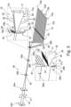
- FIG. 1 shows a schematic representation of a device 10 for producing optical tweezers.
- the device 10 comprises a laser beam source 11 which couples out a laser beam 12.
- the device 10 further comprises a plurality of acousto-optical deflectors 13, a beam splitter unit 13a which splits the laser beam 12 into a plurality of partial beams 14, namely a column 15a in this example, and a plurality of acousto-optical deflectors 13b for splitting the partial beams 14 into rows 15c.
- the rows 15c run into the image plane so that the individual partial beams in Figure 1 cannot be seen.
- An array 15 of partial beams 14 is created.
- Fourier lenses 33 are also shown purely schematically. Each row of the array 15 is assigned its own Fourier lens 33. A coupling unit 29 is also shown, after which the partial beams 14 of the array 15 pass through the staircase mirror unit 16. This is followed by a relay optics 40, after which the partial beams 14 form optical tweezers.
- the array 15 of partial beams 14 is shown in the first direction 50 and the second direction 51.
- the third direction 52, in which the partial beams propagate, extends into the image plane.
- the partial beams 14 are in the example of the Figure 2 arranged in columns 15a with a distance 15b between partial beams in a row and rows 15c with a row spacing 15d.
- section 2A it can be seen how the row spacing 15d is significantly larger than the spacing 15b of partial beams in a row. This is due in particular to the size of the acousto-optical deflectors 13b. As shown in section 2A, the array 15 is located after the Fourier lenses, especially in the focal plane of the Fourier lenses, if no staircase mirror unit is used.
- the array 15 is present after passing through the staircase mirror unit 16. More precisely, the array is present in the focal plane of the Fourier lenses when using the staircase mirror unit 16.
- the row spacing 15d is significantly reduced. It now corresponds to the spacing 15b of neighboring partial beams in a row.
- Section 2C of the Figure 2 the distance 15d of the partial beams in a row and the row spacing 15d after passing through the relay optics 40 are reduced again, preferably by a factor of 50 compared to section 2B.
- FIG 3 is a more detailed view of the device 10 of the Figure 1 can be seen. While the beam splitter unit is not visible, the acousto-optical deflectors 13b and the Fourier lenses 33 can be seen. Each row of the array 15 is assigned a Fourier lens 33. At the location of the Fourier lenses 33, the first direction 50 of the array runs in Figure 3 horizontally, while the second direction 51 runs vertically.
- the Figure 3 The beams shown after the acousto-optical deflectors 13 are columns 15a of the array 15. This is how the row spacing 15d can be seen. The spacing 15b of partial beams in a row is so much smaller in comparison that it is Figure 3 cannot be recognized.
- the partial beams 14 pass through the Fourier lenses 33 and then hit the coupling unit 29, which consists of several mirrors 30.
- the coupling unit 29 is characterized by a fixed step distance 29a and a fixed step height 29b.
- the mirrors 30 are thus each offset by a step height 29b and a step distance 29a.
- the staircase mirror unit 16 is shown in greater detail in the upper right part of the Figure 3 As can be seen, the stair mirror unit 16 consists of three components, namely a first component 17, a second component 18 and a third component 19, which are wedge-shaped. The end regions in which they taper to a point face each other.
- the first component 17 is mirror-symmetrical.
- the first component 17 has a first side surface 17a and a second side surface 17b.
- a first stair mirror 25 is arranged with mirrors 30 and a stair spacing 25a between adjacent mirrors 30 and a stair height 25b (see upper section of the Figure 3 and Figure 4 ).
- the second component 18 has a first side surface 18a, which is opposite the first side surface 17a of the first component 17. Furthermore, the third component 19 has a first side surface 19a, which is opposite the second side surface 17b of the first component 17.
- the first side surface 18a of the second Component 18 and the first side surface 19a of the third component 19 each have a second stair mirror 26 with a stair spacing 26a and a stair height 26b between mirrors 30 (see also lower section of the Figure 3 and Figure 4 ).
- FIG. 3 A further, even more detailed representation is shown in the lower detailed representation of the Figure 3 can be seen.
- the mirrors 30 of the second stair mirrors 26 on the second component 18 and the third component 19 can be seen more clearly. It can also be seen how the first component 17 has a first end region 17c.
- a third stair mirror 27 is arranged on both side surfaces of the first component 17 with a stair spacing 27a and a stair height 27b.
- the relay optics 40 which consists of two collimators 40a and a focusing lens group 40b arranged between them, is connected to the staircase mirror unit 16.
- the relay optics 40 also comprises a microscope objective 40c.
- An output mirror 41 is arranged between the second collimator 40a and the microscope objective 40c.
- the output mirror 41 lies in a pupil plane 42, which is optimally suited for coupling in radiation to excite trapped atoms or for coupling out radiation from trapped atoms.
- a second intermediate image plane 43 can be arranged after the lens group 40b.
- the row spacing 15d of the partial beams was initially reduced by means of the staircase mirror unit 16 and the coupling unit 29. A further reduction of both the row spacing 15d and the spacing 15b of partial beams in a row then takes place via the relay optics 40, among other things through the microscope objective 40c.
- Figure 4 is an enlarged view of the stair mirror unit 16 from Figure 3
- the first component 17 with the first stair mirrors 25 arranged on both sides on the respective side surfaces 17a, 17b can be clearly seen.
- three mirrors 30 of the coupling unit 29 can be seen. Their step spacing 29a and their step height 29b can be clearly seen.
- the mirrors 30 of the coupling unit 29 represent a stair mirror.
- the second component 18 and the third component 19 of the stair mirror unit 16 can be seen, which have a second stair mirror 26 on the respective first side surfaces 18a, 19a.
- the first end region 17c of the first component 17 can be clearly seen.
- a third stair mirror 27 with the stair spacing 27a and the stair height 27b is arranged on the side surfaces 17a and 17b.
- Figure 5 shows a process diagram of a method 100 for producing optical tweezers, which comprises generating 103 an array 15 of partial beams 14 and reducing 106 a row spacing 15d of the array, in other words the spacing of the partial beams of the array 15 in at least a first direction 50.
- the method 100 can comprise splitting 101 the laser beam 12 of a laser beam source 11 into partial beams 14 in the first direction and then splitting 102 the partial beams thus generated in a second direction 51 and thus into rows 15c. In this way, the array 15 is generated 103.
- the partial beams 14 of the array 15 can be coupled 104 into the stair mirror unit 16 and pass through 105 the stair mirror unit 16. In this way, the row spacing 15d of the partial beams 14 is reduced 106. A further reduction 108 of the spacing of the partial beams 14 of the array 15 in both directions is carried out in particular by passing through 107 a relay optics 40.
Landscapes
- Physics & Mathematics (AREA)
- Spectroscopy & Molecular Physics (AREA)
- Engineering & Computer Science (AREA)
- General Engineering & Computer Science (AREA)
- High Energy & Nuclear Physics (AREA)
- Nonlinear Science (AREA)
- General Physics & Mathematics (AREA)
- Optics & Photonics (AREA)
- Microscoopes, Condenser (AREA)
Abstract
Description
- Die vorliegende Erfindung betrifft eine Vorrichtung sowie ein Verfahren zur Erzeugung von optischen Pinzetten.
- Vorrichtungen zur Erzeugung von optischen Pinzetten, die bspw. zum Einfangen von Atomen für Quantencomputer dienen, sind aus dem Stand der Technik grundsätzlich bekannt. So beschreibt zum Beispiel
US 2020/0185120 A1 ein Verfahren zum Umordnen von Atomen in Arrays, wobei sich die Atome im Rydberg-Quantenzustand befinden. Ferner sind aufgrund der Anordnungen der verwendeten akustooptischen Deflektoren die Schiebebewegungen der Atome hochgradig korreliert, was eine individuelle dynamische Positionskontrolle im Array stark einschränkt. Dies liegt insbesondere daran, dass bei der Hintereinanderschaltung zweier akustooptischer Deflektoren unter einem Winkel die von dem ersten akustooptischen Deflektor erzeugte Reihe mit dem zweiten akustooptischen Deflektor mehrfach kopiert wird, um einen 2D-Array zu erzeugen. Somit lassen sich Schiebeoperationen nicht für einzelne Reihen durchführen. - Die Aufgabe der vorliegenden Erfindung ist es, eine Vorrichtung zur Erzeugung von optischen Pinzetten, vorzugsweise zum Einfangen von Atomen für einen Quantencomputer, sowie ein entsprechendes Verfahren derart weiterzuentwickeln, dass die Positionen sowie die Amplituden der optischen Pinzetten dynamisch und mit Mikrosekundengenauigkeit einstellbar sein, während ferner ein optischer Pinzettenarray mit möglichst großem Füllfaktor realisiert wird.
- Gelöst wird die vorgenannte Aufgabe durch eine Vorrichtung zur Erzeugung von optischen Pinzetten, die eine Laserstrahlquelle zur Erzeugung eines Laserstrahls umfasst. Ferner umfasst die Vorrichtung mindestens einen akustooptischen Deflektor zum Erzeugen eines Arrays an Teilstrahlen des Laserstrahls und eine Treppenspiegeleinheit umfassend mindestens einen ersten Treppenspiegel zur Reduktion eines Abstandes derTeilstrahlen des Arrays in mindestens einer ersten Richtung. Bei der Laserstrahlquelle handelt es sich insbesondere um einen Hochleistungslaser. Ein Hochleistungslaser weist insbesondere eine CW-Leistung von 10 bis 100 Watt auf. Vor allem dient die Vorrichtung zum Einfangen von Atomen für einen Quantencomputer mittels der optischen Pinzetten, die optische Fallen ausbilden.
- Mit Hilfe des mindestens einen akustooptischen Deflektors wird ein Array an Teilstrahlen des Laserstrahls erzeugt, wobei der Array Reihen umfasst. Unter einem Array ist somit vorzugsweise eine Anordnung in zwei Dimensionen zu verstehen. Die Teilstrahlen sind vorzugsweise parallel zueinander ausgerichtet. Vor allem handelt es sich bei dem Array um einen 2D-Array. Benachbarte Reihen können einen vorzugsweise konstanten Reihenabstand aufweisen. Die Teilstrahlen bilden vor allem am Ort einzufangender Atome optische Fallen aus. Hierfür sind die Teilstrahlen vor allem fokussiert.
- Die Reihen des Arrays sind vorzugsweise in eine erste Richtung beabstandet, während sich Reihen in eine zweite Richtung erstrecken. Die erste und die zweite Richtung sind vorzugsweise nicht ortsfest, sondern auf den Array bezogen, definiert. Es handelt sich um relative Richtungen. Somit können sich nach einer Reflexion des Arrays die Richtungen absolut betrachtet ändern. Die Teilstrahlen propagieren dabei in einer dritten Richtung, die senkrecht zur ersten und zweiten Richtung steht. Unter dem Abstand der Teilstrahlen in erster Richtung ist somit vorzugsweise der Reihenabstand zu verstehen. Die Teilstrahlen können in der zweiten Richtung Spalten ausbilden. Alternativ können die Teilstrahlen innerhalb unterschiedlicher Reihen ungleich verteilt sein, sodass keine Spalten ausgebildet werden. Im Falle der Ausbildung von Spalten stellt der Abstand der Teilstrahlen in zweiter Richtung den Spaltenabstand dar. Der Abstand benachbarter Teilstrahlen innerhalb einer Reihe bzw. der Spaltenabstand kann sich vom Reihenabstand unterscheiden. Ferner können diese gleich groß sein. Insbesondere umfasst eine Reihe und/oder eine Spalte des Arrays mehr als 10, vorzugsweise mehr als 15, am meisten bevorzugt mehr als 18, Teilstrahlen.
- Die Vorrichtung umfasst eine Treppenspiegeleinheit umfassend mindestens einen ersten Treppenspiegel. Die Treppenspiegeleinheit dient zur Reduktion eines Reihenabstandes der Teilstrahlen des Arrays.
- Ein Treppenspiegel umfasst eine Vielzahl von Spiegeln, die in zwei Richtungen zueinander versetzt angeordnet sind. Vorzugsweise umfasst ein Treppenspiegel mehr als 5, vorzugsweise mehr als 7, am meisten bevorzugt mehr als 9, Spiegel. Insbesondere weisen sämtliche Spiegel eines Treppenspiegels eine parallele Ausrichtung auf. Vorteilhafterweise sind sämtliche Spiegel in einem Winkel von 45° zum eintreffenden Licht und somit auch 45° zum ausgekoppelten Licht angeordnet.
- Ein Treppenspiegel umfasst einen Treppenabstand zwischen benachbarten Spiegeln und eine Treppenhöhe Die Treppenhöhe kann auch als Spiegelhöhe verstanden werden.
- Vor allem sind benachbarte Spiegel sowohl um einen Treppenabstand in erster Richtung und um eine Treppenhöhe in einer dazu senkrechten Richtung zueinander versetzt angeordnet. Benachbarte Spiegel sind vorzugsweise um den Treppenabstand in die erste Richtung versetzt. Der Versatz um eine Treppenhöhe erfolgt insbesondere in Propagationsrichtung der Teilstrahlen. Die in Bezug auf optische Einheiten, wie bspw. Treppenspiegel, angegebene Richtungen beziehen sich auf den einkommenden Array, d.h. auf den Array vor einer Reflexion.
- Durch den Versatz der Spiegel entstehen Treppen, die dem Treppenspiegel seinen Namen verleihen. Die Spiegel weisen vor allem eine Mindestbreite senkrecht zur Treppenhöhe und zum Treppenabstand auf, die der Breite des Arrays in zweiter Richtung am Ort des Treppenspiegels entspricht.
- Die Spiegel können separat angeordnet sein. In anderen Worten können diese einzeln justierbar sein. Ferner können die Spiegel als Flächen eines gemeinsamen Bauteils ausgebildet sein. Somit ist nur eine Justage des gemeinsamen Bauteils notwendig.
- Durch den Einsatz der Treppenspiegeleinheit kann der Reihenabstand des Arrays wesentlich reduziert werden, sodass der Füllfaktor des Arrays besonders groß ist. Unter dem Füllfaktor ist insbesondere das Verhältnis der 1/e2-Durchmesser Anzahl der Teilstrahlen und somit der Pinzetten pro Einheitsfläche zu verstehen. In anderen Worten sind mittels der Pinzetten eingefangene Atome bei einem höheren Füllfaktor dichter gepackt.
- Die Treppenspiegeleinheit kann mehrstufig, vor allem zweistufig oder dreistufig, ausgebildet sein. Somit kann die Treppenspiegeleinheit mehrere Treppenspiegel umfassen, die kaskadiert aufgebaut sind. Ausgehende Teilstrahlen eines Treppenspiegels erster Stufe, bspw. eines ersten Treppenspiegels, fallen auf einen Treppenspiegel nächster Stufe, bspw. einen zweiten Treppenspiegel, wobei weiter bevorzugt ausgehende Teilstrahlen des Treppenspiegels zweiter Stufe, bspw. eines zweiten Treppenspiegels, auf einen Treppenspiegel nächster Stufe, bspw. einen dritten Treppenspiegel, fallen. Die Treppenspiegel unterschiedlicher Stufe bilden somit eine Kaskade aus. Jeder Treppenspiegel ist derart angeordnet, dass benachbarte Spiegel in die erste Richtung zueinander um einen Treppenabstand versetzt sind.
- Die Treppenhöhe jedes Treppenspiegels ist vorzugsweise kleiner als dessen Treppenabstand. Das Verhältnis von Treppenhöhe zu Treppenabstand kann vor allem zwischen 0,2 und 0,4 betragen. Es kann der Treppenabstand eines Treppenspiegels vorzugsweise der Treppenhöhe des vorangehenden Treppenspiegels, d.h. des Treppenspiegels der vorangehenden Stufe, entsprechen. Insbesondere ist die Treppenhöhe und der Treppenabstand bei jedem Treppenspiegel konstant.
- Vorteilhafterweise umfasst die Treppenspiegeleinheit einen zweiten Treppenspiegel mit Spiegeln, einem Treppenabstand zwischen benachbarten Spiegeln und einer Treppenhöhe. Der Treppenabstand des zweiten Treppenspiegels entspricht vorzugsweise der Treppenhöhe des ersten Treppenspiegels. Somit treffen die Teilstrahlen des Arrays auf den ersten Treppenspiegel und im Anschluss auf den zweiten Treppenspiegel. Dabei wird der Abstand der Teilstrahlen in erster Richtung, d.h. der Reihenabstand, reduziert. Und zwar entspricht der Reihenabstand zwischen benachbarten Teilstrahlen nach Reflexion am ersten Treppenspiegel der Treppenhöhe des ersten Treppenspiegels. Es entspricht der Treppenabstand des zweiten Treppenspiegels der Treppenhöhe des ersten Treppenspiegels, sodass die Teilstrahlen auf die entsprechenden Spiegel des zweiten Treppenspiegels fallen können. Nach Durchlaufen des zweiten Treppenspiegels weisen die benachbarten Teilstrahlen einen Reihenabstand auf, der der Treppenhöhe des zweiten Treppenspiegels entspricht.
- Die Vorrichtung kann ferner einen dritten Treppenspiegel umfassen, wobei der dritte Treppenspiegel ebenfalls Spiegel, einen Treppenabstand zwischen benachbarten Spiegeln und eine Treppenhöhe aufweist. Der Treppenabstand des dritten Treppenspiegels entspricht nun vorzugsweise der Treppenhöhe des zweiten Treppenspiegels.
- Insgesamt wird der Reihenabstand mithilfe der Treppenspiegeleinheit reduziert, während der Abstand in den Reihen nicht verändert ist. Nach Durchlaufen einer mehrstufigen Treppenspiegeleinheit wird in jeder Stufe der Reihenabstand benachbarter Teilstrahlen vorzugsweise immer weiter reduziert.
- Die Treppenhöhe der Spiegel des ersten Treppenspiegels verläuft vorzugsweise in die gleiche absolute Richtung wie die Treppenhöhe des dritten Treppenspiegels. Der Treppenabstand der Spiegel der Treppenspiegel des ersten Treppenspiegels verläuft vor allem in die gleiche absolute Richtung wie der Treppenabstand des dritten Treppenspiegels. Die Treppenhöhe des zweiten Treppenspiegels verläuft insbesondere in die gleiche Richtung wie der Treppenabstand des ersten und des dritten Treppenspiegels, während der Treppenabstand des zweiten Treppenspiegels in die gleiche Richtung wie die Treppenhöhe des ersten und des dritten Treppenspiegels verlaufen kann.
- Die Treppenhöhen verschiedener Treppenspiegel der gleichen Stufe verlaufen vorzugsweise in die gleiche absolute Richtung. Der Treppenabstand verschiedener Treppenspiegel der gleichen Stufe verlaufen insbesondere in die gleiche absolute Richtung.
- Vorzugsweise kann die Treppenspiegeleinheit mehrere, vorzugsweise zwei, Treppenspiegel pro Stufe aufweisen. In einem solchen Fall bildet jeweils ein Treppenspiegel pro Stufe eine Kaskade an Treppenspiegeln aus. Weist die Treppenspiegeleinheit bspw. zwei erste, zwei zweite und zwei dritte Treppenspiegel auf, bilden diese zwei Kaskaden von Treppenspiegeln. Ein Teil, bspw. die Hälfte, der Teilstrahlen kann eine erste solche Kaskade und der andere Teil, bspw. die Hälfte, der Teilstrahlen kann eine zweite Kaskade durchlaufen. So kann bspw. die Hälfte der ausgebildeten Teilstrahlen je auf einer der beiden Seiten der Treppenspiegeleinheit eingekoppelt werden.
- Die Treppenspiegeleinheit kann insbesondere aus einem oder mehreren, bspw. drei, Bauteilen bestehen. Jedes Bauteil kann monolithisch ausgebildet sein. Jedes Bauteil kann keilförmig sein, wobei auf einer Seitenfläche mindestens ein Treppenspiegel angeordnet sein kann. Die Spiegel eines Treppenspiegels sind vorzugsweise als Oberflächen eines Bauteils ausgebildet und müssen somit nicht einzeln justiert werden.
- Die Treppenspiegeleinheit kann bspw. ein keilförmiges erstes Bauteil aufweisen, das einen ersten und einen dritten Treppenspiegel umfassen kann. Am meisten bevorzugt umfasst das erste Bauteil auf einer ersten Seitenfläche sowohl einen ersten als auch einen dritten Treppenspiegel. Ferner kann das Bauteil auf einer zweiten Seitenfläche ebenfalls einen ersten und einen dritten Treppenspiegel aufweisen. Der mindestens eine dritte Treppenspiegel kann in dem spitz zulaufenden Endbereich des keilförmigen ersten Bauteils angeordnet sein.
- Ferner kann die Treppenspiegeleinheit ein zweites Bauteil umfassen, das vorzugsweise auf einer ersten Seitenfläche einen zweiten Treppenspiegel umfasst. Die erste Seitenfläche des zweiten Bauteils ist vor allem der ersten Seitenfläche des ersten Bauteils zugewandt.
- Zudem kann die Treppenspiegeleinheit ein drittes Bauteil aufweisen, das ebenfalls vorzugsweise auf einer ersten Seitenfläche einen zweiten Treppenspiegel umfasst. Die erste Seitenfläche des dritten Bauteils ist vor allem der zweiten Seitenfläche des ersten Bauteils zugewandt. Die Treppenspiegeleinheit ist insbesondere spiegelsymmetrisch, vorzugsweise um eine Mittellinie des ersten Bauteils, ausgebildet.
- Ferner ist das zweite Bauteil und/oder das dritte Bauteil derart zum ersten Bauteil ausgerichtet, dass Teilstrahlen nach der Reflexion am ersten Treppenspiegel auf den zweiten Treppenspiegel fallen und nach Reflexion am zweiten Treppenspiegel auf den dritten Treppenspiegel fallen. Die Spiegel des ersten Treppenspiegels, des zweiten Treppenspiegels und des dritten Treppenspiegels sind vorzugsweise parallel zueinander ausgerichtet.
- Die Vorrichtung kann ferner eine Einkopplungseinheit zur Einkopplung der Teilstrahlen hinter dem mindestens einen akustooptischen Deflektor in die Treppenspiegeleinheit umfassen. Die Einkopplungseinheit dient zur präzisen Justage der Teilstrahlen in Richtung Treppenspiegeleinheit.
- Die Einkopplungseinheit kann als Treppenspiegel mit Spiegeln, einem Treppenabstand zwischen benachbarten Spiegeln und einer Treppenhöhe ausgebildet sein. Dabei sind benachbarte Spiegel erneut in erster Richtung des Arrays angeordnet. Die Treppenhöhe der Einkopplungseinheit entspricht vorzugsweise dem Treppenabstand des ersten Treppenspiegels. Es findet somit bereits bei der Einkopplungseinheit eine erste Reduktion des Abstands zwischen benachbarten Teilstrahlen in erster Richtung statt. Auch bei der Einkopplungseinheit ist die Treppenhöhe vor allem kleiner als der Treppenabstand der Einkopplungseinheit ausgebildet. Die Spiegel der Einkopplungseinheit sind vorzugsweise als separate Spiegel ausgebildet, die einzeln justierbar sind. Dies erlaubt insbesondere eine präzise Justage der einzelnen Teilstrahlen zueinander bzw. zu den folgenden Treppenspiegeln.
- Die Einkopplungseinheit kann als vorgelagerte Stufe der Treppenspiegeleinheit ausgebildet sein. Insgesamt kann somit eine vierstufige Kaskade von Treppenspiegeln vorliegen. Dabei kann die Einkopplungseinheit in die Treppenspiegeleinheit integriert sein. Bspw. kann die Einkopplungseinheit auf einem Bauteil der Treppenspiegeleinheit angeordnet sein und somit monolithisch mit mindestens einem Treppenspiegel der Treppenspiegeleinheit ausgebildet sein.
- Der Treppenabstand der Einkopplungseinheit kann zwischen 10 mm und 40 mm, vorzugsweise zwischen 20 mm und 30 mm, am meisten bevorzugt zwischen 23 mm und 27 mm, oder 25 mm betragen. Die Treppenhöhe beträgt vorzugsweise zwischen 6 mm und 10 mm, vorzugsweise zwischen 7 mm und 9 mm, oder 8 mm.
- Vorzugsweise weist die Vorrichtung mindestens eine Fourierlinse auf. Mithilfe der Fourierlinsen können die diskreten Beugungswinkel des mindestens einen akustooptischen Deflektors in vorzugsweise äquidistante Foki in ersten einer Zwischenbildebene überführt werden. Es kann sich eine bildseitig telezentrische Anordnung ergeben. Die objektseitige Brennebene der Fourierlinsen kann in der Ebene der akustooptischen Deflektoren liegen. Dann liegen die Foki in der bildseitigen Brennebene der Fourierlinsen, und die Propagationsrichtungen der Teilstrahlen sind parallel zueinander. Insbesondere weist die Vorrichtung eine Fourierlinse pro Reihe des Arrays und/oder pro akustooptischen Deflektor auf. Die Fourierlinsen sind zwischen dem mindestens einen akustooptischen Deflektor und der Treppenspiegeleinheit angeordnet.
- Zur Justage der Teilstrahlen können Keilplatten, beispielsweise Risley-Prismen, und/oder planparallele Platten vorgesehen sein, die verkippbar sind. Alternativ können lateral verschiebbare, vor allem langbrennweitige Linsen vorgesehen sein, wobei das Brennweitenverhältnis dieser Linsen zu den Fourierlinsen das Übersetzungsverhältnis der resultierenden Verschiebung der Teilstrahlen festlegt. Das Verhältnis der Brennweite der Linsen zu der der Fourierlinsen beträgt vorzugsweise größer als 5, am meisten bevorzugt größer als zehn.
- Vorzugsweise entspricht der Treppenabstand des ersten Treppenspiegels zwischen 4 mm und 12 mm, vorzugsweise zwischen 6 mm und 10 mm oder zwischen 7 mm und 9 mm. Ferner bevorzugt kann der Treppenabstand zwischen 7,5 mm und 8,5 mm, am meisten bevorzugt 8 mm betragen. Die Treppenhöhe des ersten Treppenspiegels beträgt insbesondere zwischen 0,5 mm und 3,5 mm, bevorzugterweise zwischen 1 mm und 3 mm, ferner bevorzugt zwischen 1,5 mm und 2,5 mm, am meisten bevorzugt 2 mm.
- Der Treppenabstand des zweiten Treppenspiegels beträgt insbesondere zwischen 0,5 mm und 3,5 mm, vorzugsweise zwischen 1 mm und 3 mm, ferner bevorzugt zwischen 1,5 mm und 2,5 mm, am meisten bevorzugt 2 mm. Die Treppenhöhe des zweiten Treppenspiegels beträgt vorzugsweise zwischen 0,25 mm und 0,75 mm, bevorzugterweise zwischen 0,4 mm und 0,6 mm, am meisten bevorzugt zwischen 0,45 mm und 0,55 mm. Ferner kann die Treppenhöhe 0,5 mm betragen.
- Der Treppenabstand des dritten Treppenspiegels beträgt vorzugsweise zwischen 0,25 mm und 0,75 mm, ferner bevorzugt zwischen 0,4 mm und 0,6 mm, am meisten bevorzugt zwischen 0,45 mm und 0,55 mm. Ferner kann der Treppenabstand 0,5 mm betragen. Die Treppenhöhe des dritten Treppenspiegels beträgt vorzugsweise zwischen 0,1 mm und 0,3 mm, bevorzugterweise zwischen 0,15 mm und 0,2 mm, am meisten bevorzugt zwischen 0,16 mm und 0,19 mm. Ferner kann die Treppenhöhe 0,1875 mm betragen.
- Vorzugsweise umfasst die Vorrichtung eine Strahlteilereinheit zur Aufteilung des Laserstrahls in erster Richtung, vorzugsweise in eine Spalte an Teilstrahlen, in anderen Worten wird der Laserstrahl in mehrere Teilstrahlen in erster Richtung aufgeteilt. Das heißt, die Strahlteilereinheit hat insbesondere einen Eingang und mehrere Ausgänge in erster Richtung. Die Strahlteilereinheit kann mehrere Strahlteiler umfassen. Ferner kann die Strahlteilereinheit als akustooptischer Deflektor ausgebildet sein.
- Die Vorrichtung kann pro auszubildende Reihe des Arrays einen eigenen akustooptischen Deflektor umfassen. Insbesondere umfasst die Vorrichtung pro Teilstrahl, der die Strahlteilereinheit verlässt, jeweils einen eigenen akustooptischen Deflektor zum Aufteilen des jeweiligen Teilstrahls in eine zweite Richtung und somit zum Erzeugen mehrerer Reihen und somit des Arrays an Teilstrahlen. Der Abstand der akustooptischen Deflektoren entspricht vorzugsweise dem Abstand der Teilstrahlen nach der Strahlteilereinheit. Jeder akustooptische Deflektor ist insbesondere als einachsiger akustooptischer Deflektor mit einem einzigen Eingang und einer Mehrzahl von Ausgängen ausgebildet. Der Abstand der Ausgänge entspricht dem Abstand der Teilstrahlen in zweiter Richtung nach den Fourierlinsen.
- Während somit die Strahlteilereinheit eine Vielzahl von Teilstrahlen in erster Richtung erzeugt, erzeugen die akustooptischen Deflektoren jeweils eine Reihe, sodass insgesamt ein Array entsteht. Insbesondere entspricht der Treppenabstand der Einkopplungseinheit dem Abstand der akustooptischen Deflektoren.
- Aufgrund des bautechnisch bedingten Abstands der akustooptischen Deflektoren ist der Reihenabstand wesentlich größer als der Abstand innerhalb einer Reihe. Dies begrenzt maßgeblich den Füllfaktor. Obwohl der Abstand der Teilstrahlen in erster Richtung zunächst dem Abstand der akustooptischen Deflektoren entspricht, wird dieser durch die Treppenspiegeleinheit und vorzugsweise die Einkopplungseinheit in erster Richtung reduziert. Insbesondere entspricht der Reihenabstand der Teilstrahlen des Arrays nach der Treppenspiegeleinheit dem Abstand von Teilstrahlen innerhalb der Reihen. In anderen Worten wird der Reihenabstand der Teilstrahlen mittels der Treppenspiegeleinheit und ggfs. der Einkopplungseinheit an den Abstand benachbarter Teilstrahlen innerhalb einer Reihe angeglichen. Die Treppenspiegeleinheit ggfs. zusammen mit der Einkopplungseinheit ist dazu ausgebildet den Reihenabstand um vorzugsweise etwa zwei Größenordnungen zu reduzieren. Während der Reihenabstand nach den akustooptischen Deflektoren in etwa ein paar Zentimeter beträgt, beträgt er nach Durchlaufen der Treppenspiegeleinheit in etwa 200 Mikrometer.
- Ferner bevorzugt kann die Vorrichtung eine Relaisoptik umfassen, die vorzugsweise ein Mikroskopobjektiv aufweist. Das Mikroskopobjektiv kann eine Brennweite zwischen 5 mm und 50 mm, vorzugsweise zwischen 30 mm und 35 mm, vorzugsweise 33 mm, aufweisen. Ferner kann das Mikroskopobjektiv eine numerische Apertur zwischen 0,1 und 1,0, vorzugsweise zwischen 0,4 und 0,6, aufweisen.
- Die Relaisoptik dient zur Reduktion des Reihenabstandes und des Abstandes benachbarter Teilstrahlen innerhalb einer Reihe. Mit Hilfe der Relaisoptik werden nach Durchlaufen der Treppenspiegeleinheit somit die Ausmaße des gesamten Arrays reduziert. Es werden somit der Abstand in erster Richtung und der Abstand in zweiter Richtung gleichermaßen reduziert. Der Füllfaktor ändert sich somit hier nicht.
- Insbesondere ist die Relaisoptik zweistufig ausgebildet, wobei beide Stufen das gleiche Abbildungsverhältnis aufweisen können. Ferner kann die Relaisoptik mehr als zwei Stufen aufweisen. Die Relaisoptik umfasst vorzugsweise zwei Kollimatoren, die vor dem Mikroskopobjektiv angeordnet sind, und mindestens eine zwischen den Kollimatoren angeordnete Linse, vor allem eine Fokuslinse, in deren Brennebene ein weiteres, vorzugsweise telezentrisches zweites Zwischenbild entstehen kann. Ferner kann zwischen den Kollimatoren eine fokussierende Gruppe von Linsen angeordnet sein. Der erste und/oder der zweite Kollimator kann eine Brennweite vorzugsweise zwischen 200 mm und 300 mm aufweisen.
- Der zweistufige Aufbau reduziert die Baugröße der Relaisoptik und somit die der gesamten Vorrichtung. Insbesondere ist die fokussierende Gruppe in der Mitte zwischen den Kollimatoren angeordnet. Ferner kann die Relaisoptik beidseitig telezentrisch ausgebildet sein. Die Relaisoptik kann aus den zwei Kollimatoren, der fokussierenden Gruppe und dem Mikroskopobjektiv bestehen. Unter einer Gruppe sind vorzugsweise mehr als zwei Linsen zu verstehen.
- Die Relaisoptik ist vor allem dazu ausgebildet, den Array nach der Treppenspiegeleinheit um einen Faktor von mindestens 20, vorzugsweise mindestens 30, am meistens bevorzugt mindestens 50 verkleinert abzubilden. Nach Durchlaufen der Relaisoptik umfasst der Array einen Reihenabstand und/oder Abstand benachbarter Teilstrahlen innerhalb einer Reihe zwischen 1 µm und 5 µm, vorzugsweise zwischen 2 µm und 4 µm, am meisten bevorzugt in etwa 3 µm.
- Nach der Relaisoptik bilden die Teilstrahlen optische Pinzetten. Eine optische Pinzette ist dazu ausgebildet, ein einzelnes Atom an dessen Position zu fixieren. Insbesondere wird die Vorrichtung dazu eingesetzt, Atome für einen Quantencomputer zu fixieren. Bei den Atomen handelt es sich insbesondere um Rydberg-Atome. Dies heißt, dass die Atome angeregt sind. Im Detail ist mindestens ein Elektron der Elektronenhülle in einem hohen Zustand, und zwar in einem sogenannten Rydberg-Zustand. Ein Atom kann jeweils an der Strahltaille, d.h. der schmalsten Stelle, eines Teilstrahls nach der Relaisoptik festgehalten werden.
- Ferner kann die Vorrichtung eine Einheit zum Einkoppeln von Strahlung zur Anregung von mittels der optischen Pinzetten eingefangener Atome und/oder zur Auskopplung von Strahlung, die von mittels der optischen Pinzetten eingefangenen Atome stammt. Die Einheit ist zur Einkopplung und/oder Auskopplung in einer Pupillenebene der Relaisoptik ausgebildet. Die Relaisoptik kann zwei Pupillenebenen, nämlich eine erste und eine zweite Pupillenebene, aufweisen. Die Ein- und Auskopplung in einer Pupillenebene ist besonders bevorzugt, da hier Strahltaillen der Teilstrahlen liegen und diese überlagert sind, so dass der Gesamtdurchmesser aller Teilstrahlen minimal ist. Es entsteht somit kein Astigmatismus durch die schräggestellten Spiegel. Die beiden Pupillenebenen liegen vor allem zwischen dem ersten und dem zweiten Kollimator, und zwar liegt vorzugsweise eine Pupillenebene in der Brennebene des zweiten Kollimators der Relaisoptik.
- Die Vorrichtung kann dazu ausgebildet sein, die Position einzelner Atome zu verschieben. Vor allem kann das Verschieben der Atome während Gatteropertionen eines tiefen Quantencomputer-Algorithmus erfolgen. Die Bewegung der Atome erlaubt die Konnektivität - in Rydberg-Systemen typischerweise eine Nächste-Nachbar Konnektivität - dynamisch zu verändern. So lässt sich bspw. durch Verschieben eine direkte Verschränkung zwischen ursprünglich oder später im Algorithmus weit voneinander entfernten Atomen erzeugen. Somit wird die Realisierung eines Qubit-Registers mit dynamischer Konnektivität über nächste Nachbarn hinaus ermöglicht.
- Der Einsatz akustooptischer Deflektoren ist grundsätzlich besonders vorteilhaft, da sie eine möglichst kleine Ansprechzeit aufweisen und somit dazu ausgebildet sind, die Teilstrahlen und somit die Positionen der optischen Pinzetten in Mikrosekundenschnelle zu verschieben. Eine Verschiebung wird erreicht, indem ein Hochfrequenzsignal, mit dem der jeweilige akustooptische Deflektor angesteuert wird, verändert wird. So verschiebt sich die Position der optischen Pinzette, vorzugsweise proportional zur Frequenzverschiebung. Eine Änderung der Hochfrequenz wird somit direkt in eine Änderung der Position der optischen Pinzetten übersetzt.
- Dadurch, dass jeder Reihe ein eigener akustooptischer Deflektor, und zwar genau ein Deflektor, zugeordnet sein kann, können die Positionen eingefangener Atome innerhalb der einzelnen Reihen unabhängig voneinander verändert werden. Der Abstand in jeder Reihe kann insbesondere auf Mikrosekundenskala verändert werden. Es sind Schiebeoperationen eingefangener Atome somit minimal korreliert. Es kann eine möglichst schnelle und hochgradig parallele Positionsverschiebung erfolgen, was besonders vorteilhaft ist, da eine entsprechende Umordnung bei einem Quantencomputer eine hohe Anzahl von optischen Pinzetten betrifft. Die Vorrichtung dient somit als zentraler Baustein für einen Quantencomputer.
- Ferner ist die Vorrichtung dazu ausgebildet, die Amplituden der einzelnen Pinzetten einer Reihe unabhängig von denen anderer Reihen zu verändern, da jeder Reihe des Arrays ein eigener akustooptischer Deflektor zugeordnet ist. Dies wird durch eine Einstellung der Amplitude des Hochfrequenzsignals erreicht. Insgesamt können somit Positionen sowie die Amplituden der optischen Pinzetten dynamisch und mit Mikrosekundengenauigkeit eingestellt werden.
- Ferner kann sich die Erfindung auf einen Quantencomputer umfassend eine oben beschriebene Vorrichtung beziehen.
- In einem weiteren Aspekt betrifft die vorliegende Erfindung ein Verfahren zur Erzeugung von optischen Pinzetten, vorzugsweise zum Einfangen von Atomen für einen Quantencomputer, wobei das Verfahren eine Erzeugung eines Laserstrahls mittels einer Laserstrahlquelle umfasst.
- Ferner umfasst das Verfahren ein Erzeugen eines Arrays an Teilstrahlen mittels mindestens eines akustooptischen Deflektors und eine Reduktion eines Reihenabstandes der Teilstrahlen des Arrays mittels einer Treppenspiegeleinheit, umfassend mindestens einen ersten Treppenspiegel, wobei der erste Treppenspiegel Spiegel, einen Abstand zwischen benachbarten Spiegeln und eine Treppenhöhe umfasst. Insbesondere umfasst das Verfahren ein Aufteilen des Laserstrahls in Teilstrahlen in die erste Richtung mittels einer Strahlteilereinheit und ein jeweiliges Aufteilen jedes Teilstrahls in eine Reihe und somit das Erzeugen des Arrays an Teilstrahlen mittels eines jeweiligen akustooptischen Deflektors.
- Das Verfahren kann ferner das Einkoppeln der Teilstrahlen des Arrays in die Treppenspiegeleinheit umfassen, und zwar vorzugsweise mittels einer Einkopplungseinheit. Ferner kann das Verfahren das Durchlaufen der Treppenspiegeleinheit umfassen, nämlich die Reflexion am ersten Treppenspiegel und vorzugsweise am zweiten Treppenspiegel und ferner bevorzugt am dritten Treppenspiegel. Es wird sowohl bei der Einkopplungseinheit als auch bei jedem Treppenspiegel der Treppenspiegeleinheit der Abstand der Teilstrahlen in erster Richtung reduziert. Ferner kann das Verfahren eine weitere Reduktion des Abstandes der Teilstrahlen sowohl in erster Richtung als auch in zweiter Richtung umfassen, vorzugsweise mittels einer Relaisoptik, die ein Mikroskopobjektiv aufweisen kann.
- Insbesondere ist das Verfahren mittels der oben genannten Vorrichtung auszuführen und die Vorrichtung zur Durchführung des Verfahrens ausgebildet.
- Es zeigen in rein schematischer Darstellung:
- Figur 1:
- eine Vorrichtung zur Erzeugung von optischen Pinzetten;
- Figur 2:
- ein Array an Teilstrahlen,
- Figur 3:
- eine detaillierte Ansicht der Vorrichtung der
Figur 1 , und - Figur 4:
- eine vergrößerte Darstellung der Treppenspiegeleinheit der
Figur 3 ; und - Figur 5:
- ein Verfahrensschema eines Verfahrens zur Erzeugung optischer Pinzetten.
-
Figur 1 zeigt eine schematische Darstellung einer Vorrichtung 10 zur Erzeugung von optischen Pinzetten. Die Vorrichtung 10 umfasst eine Laserstrahlquelle 11, die einen Laserstrahl 12 auskoppelt. Ferner umfasst die Vorrichtung 10 mehrere akustooptische Deflektoren 13, eine Strahlteilereinheit 13a, die den Laserstrahl 12 in eine Vielzahl von Teilstrahlen 14, und zwar in diesem Beispiel eine Spalte 15a, aufteilt, und eine Vielzahl von akustooptischen Deflektoren 13b zum Aufteilen der Teilstrahlen 14 in Reihen 15c. Die Reihen 15c verlaufen in die Bildebene, sodass die einzelnen Teilstrahlen inFigur 1 nicht zu sehen sind. Es entsteht ein Array 15 an Teilstrahlen 14. - Rein schematisch sind ferner Fourierlinsen 33 dargestellt. Jeder Reihe des Arrays 15 ist eine eigene Fourierlinse 33 zugeordnet. Ferner ist eine Einkopplungseinheit 29 dargestellt, nach der die Teilstrahlen 14 des Arrays 15 die Treppenspiegeleinheit 16 durchlaufen. Danach folgt eine Relaisoptik 40, nach der die Teilstahlen 14 optische Pinzetten ausbilden.
- In
Figur 2 ist der Array 15 an Teilstrahlen 14 in erste Richtung 50 und zweite Richtung 51 gezeigt. Die dritte Richtung 52, in die die Teilstrahlen propagieren, erstreckt sich in die Bildebene. Die Teilstrahlen 14 sind in dem Beispiel derFigur 2 in Spalten 15a mit einem Abstand 15b zwischen Teilstrahlen in einer Reihe und Reihen 15c mit einem Reihenabstand 15d angeordnet. - In Abschnitt 2A ist zu sehen, wie der Reihenabstand 15d wesentlich größer ist als der Abstand 15b von Teilstrahlen in einer Reihe. Dies ist insbesondere durch die Baugröße der akustooptischen Deflektoren 13b bedingt. Wie in Abschnitt 2A gezeigt, liegt der Array 15 nach den Fourierlinsen, vor allem in der Brennebene der Fourierlinsen vor, wenn keine Treppenspiegeleinheit eingesetzt wird.
- In Abschnitt 2B ist der Array 15 nach Durchlaufen der Treppenspiegeleinheit 16 vor. Genauer liegt der Array so bei Verwendung der Treppenspiegeleinheit 16 in der Brennebene der Fourierlinsen vor. Der Reihenabstand 15d ist wesentlich reduziert. Er entspricht nun dem Abstand 15b benachbarter Teilstrahlen in einer Reihe.
- In Abschnitt 2C der
Figur 2 ist der Abstand 15d der Teilstrahlen in einer Reihe und der Reihenabstand 15d nach Durchlaufen der Relaisoptik 40 nochmals reduziert, und zwar vorzugsweise um einen Faktor 50 im Vergleich zu Abschnitt 2B. - In
Figur 3 ist eine detailliertere Ansicht der Vorrichtung 10 derFigur 1 zu sehen. Während die Strahlteilereinheit nicht zu sehen ist, sind die akustooptischen Deflektoren 13b und die Fourierlinsen 33 zu sehen. Jeder Reihe des Arrays 15 ist eine Fourierlinse 33 zugeordnet. An der Stelle der Fourierlinsen 33 verläuft die erste Richtung 50 des Arrays inFigur 3 horizontal, während die zweite Richtung 51 vertikal verläuft. Die inFigur 3 nach den akustooptischen Deflektoren 13 dargestellten Strahlen sind Spalten 15a des Arrays 15. So ist der Reihenabstand 15d zu sehen. Der Abstand 15b von Teilstrahlen in einer Reihe ist im Vergleich so viel kleiner, dass er inFigur 3 nicht zu erkennen ist. - In
Figur 3 sind nur die zehn untersten Reihen 15c des Arrays 15 gezeigt, die auf einer Seite der Treppenspiegeleinheit 16 eingekoppelt werden. Weitere Reihen 15c des Arrays 15 werden auf der anderen Seite der Treppenspiegeleinheit 16, die im Folgenden noch detaillierter beschrieben wird, eingekoppelt. - Die Teilstrahlen 14 durchlaufen die Fourierlinsen 33 und treffen dann auf die Einkopplungseinheit 29, die aus mehreren Spiegeln 30 besteht. Die Einkopplungseinheit 29 ist durch einen festen Treppenabstand 29a und durch eine feste Treppenhöhe 29b charakterisiert. Die Spiegel 30 sind somit jeweils um eine Treppenhöhe 29b und einen Treppenabstand 29a versetzt.
- Die Treppenspiegeleinheit 16 ist im größeren Detail im oberen rechten Bildausschnitt der
Figur 3 dargestellt. Wie zu sehen ist, besteht die Treppenspiegeleinheit 16 aus drei Bauteilen, und zwar einem ersten Bauteil 17, einem zweiten Bauteil 18 und einem dritten Bauteil 19, die keilförmig ausgebildet sind Die Endbereiche, in denen diese spitz zulaufen, sind einander zugewandt. Das erste Bauteil 17 ist dabei spiegelsymmetrisch ausgebildet. - Das erste Bauteil 17 weist eine erste Seitenfläche 17a auf und eine zweite Seitenfläche 17b. Auf jeder der beiden vorgenannten Seitenflächen ist jeweils ein erster Treppenspiegel 25 angeordnet mit Spiegeln 30 und einem Treppenabstand 25a zwischen benachbarten Spiegeln 30 und einer Treppenhöhe 25b (siehe oberen Ausschnitt der
Figur 3 undFigur 4 ). - Das zweite Bauteil 18 weist eine erste Seitenfläche 18a auf, die der ersten Seitenfläche 17a des ersten Bauteils 17 gegenübersteht. Ferner weist das dritte Bauteil 19 eine erste Seitenfläche 19a auf, die der zweiten Seitenfläche 17b des ersten Bauteils 17 gegenübersteht. Die erste Seitenfläche 18a des zweiten Bauteils 18 und die erste Seitenfläche 19a des dritten Bauteils 19 weisen jeweils einen zweiten Treppenspiegel 26 auf mit einem Treppenabstand 26a und einer Treppenhöhe 26b zwischen Spiegeln 30 (siehe auch unteren Ausschnitt der
Figur 3 undFigur 4 ). - Eine weitere noch detailliertere Darstellung ist in der unteren Detaildarstellung der
Figur 3 zu sehen. Deutlicher sind die Spiegel 30 der zweiten Treppenspiegel 26 auf dem zweiten Bauteil 18 und dem dritten Bauteil 19 zu sehen. Ferner ist zu erkennen, wie das erste Bauteil 17 einen ersten Endbereich 17c aufweist. In dem ersten Endbereich 17c des ersten Bauteils 17 ist auf beiden Seitenflächen des ersten Bauteils 17 jeweils ein dritter Treppenspiegel 27 angeordnet mit einem Treppenabstand 27a und einer Treppenhöhe 27b. - An die Treppenspiegeleinheit 16 schließt sich die Relaisoptik 40 an, die aus zwei Kollimatoren 40a besteht und einer dazwischen angeordneten fokussierenden Linsengruppe 40b. Ferner umfasst die Relaisoptik 40 ein Mikroskopobjektiv 40c. Ein Auskoppelspiegel 41 ist zwischen dem zweiten Kollimator 40a und dem Mikroskopobjektiv 40c angeordnet.. Der Auskoppelspiegel 41 liegt in einer Pupillenebene 42, die sich optimal zum Einkoppeln von Strahlung zur Anregung eingefangener Atome oder zum Auskoppeln von Strahlung eingefangener Atome eignet. Nach der Linsengruppe 40b kann eine zweite Zwischenbildebene 43 angeordnet sein.
- Der Reihenabstand 15d der Teilstrahlen wurde zunächst mittels der Treppenspiegeleinheit 16 und der Einkopplungseinheit 29 reduziert. Eine weitere Reduktion sowohl des Reihenabstandes 15d als auch des Abstandes 15b von Teilstrahlen in einer Reihe findet dann über die Relaisoptik 40 unter anderem durch das Mikroskopobjektiv 40c, statt.
- In
Figur 4 ist eine vergrößerte Darstellung der Treppenspiegeleinheit 16 ausFigur 3 zu sehen. Deutlich ist das erste Bauteil 17 mit beidseitig angeordneten ersten Treppenspiegeln 25 auf den jeweiligen Seitenflächen 17a, 17b zu sehen. Ferner sind drei Spiegel 30 der Einkopplungseinheit 29 zu sehen. Deutlich ist deren Treppenabstand 29a und deren Treppenhöhe 29b zu erkennen. - Durch die versetzte Anordnung der Spiegel 30 der Einkopplungseinheit 29 stellen diese einen Treppenspiegel dar. Ferner sind das zweite Bauteil 18 und das dritte Bauteil 19 der Treppenspiegeleinheit 16 zu sehen, die auf den jeweiligen ersten Seitenflächen 18a, 19a einen zweiten Treppenspiegel 26 aufweisen. In der vergrößerten Darstellung auf der rechten Seite der
Figur 4 ist insbesondere der erste Endbereich 17c des ersten Bauteils 17 deutlich zu sehen. Auf den Seitenflächen 17a und 17b sind jeweils ein dritter Treppenspiegel 27 mit dem Treppenabstand 27a und der Treppenhöhe 27b angeordnet. -
Figur 5 zeigt ein Verfahrensschema eines Verfahrens 100 zur Erzeugung von optischen Pinzetten, das ein Erzeugen 103 eines Arrays 15 an Teilstrahlen 14 und eine Reduktion 106 eines Reihenabstandes 15d des Arrays, in anderen Worten des Abstands der Teilstrahlen des Arrays 15 in mindestens einer ersten Richtung 50, umfasst. - Zunächst kann das Verfahren 100 das Aufteilen 101 des Laserstrahls 12 einer Laserstrahlquelle 11 in Teilstrahlen 14 in erster Richtung und im Anschluss das Aufteilen 102 der so erzeugten Teilstrahlen in eine zweite Richtung 51 und somit in Reihen 15c umfassen. Auf diese Weise wird der Array 15 erzeugt 103.
- Im Anschluss können die Teilstrahlen 14 des Arrays 15 in die Treppenspiegeleinheit 16 eingekoppelt werden 104 und die Treppenspiegeleinheit 16 durchlaufen 105. So wird der Reihenabstand 15d der Teilstrahlen 14 reduziert 106. Eine weitere Reduktion 108 des Abstandes der Teilstrahlen 14 des Arrays 15 in beide Richtungen erfolgt insbesondere durch Durchlaufen 107 einer Relaisoptik 40.
-
- 10
- Vorrichtung
- 11
- Laserstrahlquelle
- 12
- Laserstrahl
- 13
- akustooptischer Deflektor
- 13a
- Strahlteilereinheit
- 13b
- akustooptischer Deflektor
- 14
- Teilstrahlen
- 15
- Array
- 15a
- Spalte
- 15b
- Abstand innerhalb einer Reihe
- 15c
- Reihe
- 15d
- Reihenabstand
- 16
- Treppenspiegeleinheit
- 17
- erstes Bauteil
- 17a
- erste Seitenfläche des ersten Bauteils
- 17b
- zweite Seitenfläche des ersten Bauteils
- 17c
- erster Endbereich des ersten Bauteils
- 18
- zweites Bauteil
- 18a
- erste Seitenfläche des zweiten Bauteils
- 19
- drittes Bauteil
- 19a
- erste Seitenfläche des dritten Bauteils
- 25
- erster Treppenspiegel
- 25a
- Treppenabstand des ersten Treppenspiegels
- 25b
- Treppenhöhe des ersten Treppenspiegels
- 26
- zweiter Treppenspiegel
- 26a
- Treppenabstand des zweiten Treppenspiegels
- 26b
- Treppenhöhe des zweiten Treppenspiegels
- 27
- dritter Treppenspiegel
- 27a
- Treppenabstand des dritten Treppenspiegels
- 27b
- Treppenhöhe des dritten Treppenspiegels
- 29
- Einkopplungseinheit
- 29a
- Treppenabstand der Einkopplungseinheit
- 29b
- Treppenhöhe der Einkopplungseinheit
- 30
- Spiegel
- 33
- Fourierlinsen
- 40
- Relaisoptik
- 40a
- Kollimator
- 40b
- fokussierende Linsengruppe
- 40c
- Mikroskopobjektiv
- 41
- Auskoppelspiegel
- 42
- Pupillenebene
- 43
- zweite Zwischenbildebene
- 50
- erste Richtung
- 51
- zweite Richtung
- 52
- dritte Richtung
- 100
- Verfahren zur Erzeugung von optischen Pinzetten
- 101
- Aufteilen des Laserstrahls in Teilstrahlen in eine Spalte
- 102
- Aufteilen der Teilstrahlen in Reihen
- 103
- Erzeugen eines Arrays an Teilstrahlen
- 104
- Einkoppeln der Teilstrahlen des Arrays in die Treppenspiegeleinheit
- 105
- Durchlaufen der Treppenspiegeleinheit
- 106
- Reduktion eines Reihenabstandes der Teilstrahlen des Arrays
- 107
- Durchlaufen der Relaisoptik
- 108
- Reduktion des Reihenabstandes und Abstandes der Teilstrahlen in einer Reihe
Claims (13)
- Vorrichtung (10) zur Erzeugung von optischen Pinzetten,
umfassendeine Laserstrahlquelle (11) zur Erzeugung eines Laserstrahls (12), und mindestens einen akustooptischen Deflektor (13) zum Erzeugen eines Arrays (15) an Teilstrahlen (14) des Laserstrahls (12),wobei der Array (15) Reihen (15c) umfasst,dadurch gekennzeichnet, dassdie Vorrichtung (10) eine Treppenspiegeleinheit (16) umfassend mindestens einen ersten Treppenspiegel (25) zur Reduktion eines Reihenabstandes (15d) der Teilstrahlen (14) des Arrays (15) aufweist, wobei der erste Treppenspiegel (25) Spiegel (30), einen Treppenabstand (25a) zwischen benachbarten Spiegeln (30) und eine Treppenhöhe (25b) umfasst. - Vorrichtung (10) nach Anspruch 1,
dadurch gekennzeichnet, dass
die Treppenspiegeleinheit (16) mehrstufig, vorzugsweise zwei- oder dreistufig, ausgebildet ist. - Vorrichtung (10) nach Anspruch 1 oder 2,
dadurch gekennzeichnet, dassdie Treppenspiegeleinheit (10) einen zweiten Treppenspiegel (26) umfasst, wobei der zweite Treppenspiegel (26) Spiegel (30), einen Treppenabstand (26a) zwischen benachbarten Spiegeln (30) und eine Treppenhöhe (26b) umfasst,wobei der Treppenabstand (26a) des zweiten Treppenspiegels (26) der Treppenhöhe (25b) des ersten Treppenspiegels (25) entspricht. - Vorrichtung (10) nach Anspruch 3,
dadurch gekennzeichnet, dassdie Treppenspiegeleinheit (16) einen dritten Treppenspiegel (27) umfasst,wobei der dritte Treppenspiegel (27) Spiegel (30), einen Treppenabstand (27a) zwischen benachbarten Spiegeln (30) und eine Treppenhöhe (27b) umfasst,wobei der Treppenabstand (27a) des dritten Treppenspiegels der Treppenhöhe (26b) des zweiten Treppenspiegels (26) entspricht. - Vorrichtung (10) nach einem der vorangehenden Ansprüche,
dadurch gekennzeichnet, dassdie Vorrichtung (10) eine Einkopplungseinheit (29) zur Einkopplung der Teilstrahlen in die Treppenspiegeleinheit (16) umfasst,wobei die Einkopplungseinheit (29) Spiegel (30), einen Treppenabstand (29a) zwischen benachbarten Spiegeln (30) und eine Treppenhöhe (29b) umfasst,wobei die Treppenhöhe (29b) der Einkopplungseinheit (29) dem Treppenabstand (25a) des ersten Treppenspiegels (25) entspricht. - Vorrichtung (10) nach einem der vorangehenden Ansprüche,
dadurch gekennzeichnet, dassdie Treppenhöhe (25b) des ersten Treppenspiegels (25) kleiner ist als der Treppenabstand (25a) des ersten Treppenspiegels (25) und/oderdie Treppenhöhe (26b) des zweiten Treppenspiegels (26) kleiner ist als der Treppenabstand (26a) des zweiten Treppenspiegels (26) und/oderdie Treppenhöhe (27a) des dritten Treppenspiegels (27) kleiner ist als der Treppenabstand (27b) des dritten Treppenspiegels (27), und/oderdie Treppenhöhe (29b) der Einkopplungseinheit (29) kleiner ist als der Treppenabstand (29a) der Einkopplungseinheit (29). - Vorrichtung (10) nach einem der vorangehenden Ansprüche,
dadurch gekennzeichnet, dassder Treppenabstand (25a) des ersten Treppenspiegels (25) zwischen 4 mm und 12 mm, vorzugsweise zwischen 6 mm und 10 mm, am meisten bevorzugt zwischen 7 mm und 9 mm, und/oderdie Treppenhöhe (25b) des ersten Treppenspiegels (25) zwischen 0,5 mm und 3,5 mm, bevorzugterweise zwischen 1 mm und 3 mm, beträgt. - Vorrichtung (10) nach einem der Ansprüche 3 bis 7,
dadurch gekennzeichnet, dassder Treppenabstand (26a) des zweiten Treppenspiegels (26) zwischen 0,5 mm und 3,5 mm, vorzugsweise zwischen 1 mm und 3 mm, und/oderdie Treppenhöhe (26b) des zweiten Treppenspiegels (26) zwischen 0,25 mm und 0,75 mm, bevorzugterweise zwischen 0,4 mm und 0,6 mm, beträgt. - Vorrichtung (10) nach einem der Ansprüche 4 bis 8,
dadurch gekennzeichnet, dassder Treppenabstand (27a) des dritten Treppenspiegels (27) zwischen 0,25 mm und 0,75 mm, vorzugsweise zwischen 0,4 mm und 0,6 mm,und/oder die Treppenhöhe (27b) des dritten Treppenspiegels (27) zwischen 0,10 mm und 0,30 mm, bevorzugterweise zwischen 0,150 mm und 0,20 mm, beträgt. - Vorrichtung (10) nach einem der vorangehenden Ansprüche,
dadurch gekennzeichnet, dass
die Vorrichtung (10) eine Strahlteilereinheit (13a) zur Aufteilung des Laserstrahls (12) in Teilstrahlen (14) in eine erste Richtung (50) umfasst, wobei die Vorrichtung (10) pro Teilstrahl (14) einen akustooptischen Deflektor (13b) zum Aufteilen der Teilstrahlen (14) in Reihen (15c) und somit zum Erzeugen des Arrays (15) an Teilstrahlen (14) umfasst. - Vorrichtung (10) nach einem der vorangehenden Ansprüche,
dadurch gekennzeichnet, dassdie Vorrichtung (10) eine Relaisoptik (40) umfassend ein Mikroskopobjektiv (40c) zur Reduktion des Reihenabstandes (15d) und des Abstandes von Teilstrahlen (14) innerhalb einer Reihe umfasst,wobei die Teilstrahlen (14) nach der Relaisoptik (40) optische Pinzetten zum Einfangen von Atomen ausbilden. - Vorrichtung (10) nach einem der Ansprüche,
dadurch gekennzeichnet, dassdie Vorrichtung (10) eine Einheit zum Einkoppeln von Strahlung zur Anregung von mittels der optischen Pinzetten eingefangenen Atomen und/oder zur Auskopplung von von mittels der optischen Pinzetten eingefangenen Atomen stammender Strahlung aufweist,wobei die Einheit zur Einkopplung und/oder Auskopplung in einer Pupillenebene (42) der Relaisoptik (40) ausgebildet ist. - Verfahren (100) zur Erzeugung von optischen Pinzetten,wobei das Verfahren (100) ein Erzeugen (103) eines Arrays (15) an Teilstrahlen (14) mittels mindestens eines akustooptischen Deflektors (13) umfasst,wobei der Array (15) Reihen (15c) umfasst,dadurch gekennzeichnet, dassdas Verfahren (100) eine Reduktion (1069 eines Reihenabstandes (15d) der Teilstrahlen (14) des Arrays (15) mittels einer Treppenspiegeleinheit (16) aufweisend mindestens einen ersten Treppenspiegel (25) umfasst, wobei der erste Treppenspiegel (25) Spiegel (30), einen Treppenabstand (25a) zwischen benachbarten Spiegeln (30) und eine Treppenhöhe (25b) umfasst.
Priority Applications (2)
| Application Number | Priority Date | Filing Date | Title |
|---|---|---|---|
| EP22211813.5A EP4383002B1 (de) | 2022-12-06 | 2022-12-06 | Vorrichtung und verfahren zur erzeugung von optischen pinzetten |
| US18/530,288 US20240194367A1 (en) | 2022-12-06 | 2023-12-06 | Device and Method for Generating Optical Tweezers |
Applications Claiming Priority (1)
| Application Number | Priority Date | Filing Date | Title |
|---|---|---|---|
| EP22211813.5A EP4383002B1 (de) | 2022-12-06 | 2022-12-06 | Vorrichtung und verfahren zur erzeugung von optischen pinzetten |
Publications (3)
| Publication Number | Publication Date |
|---|---|
| EP4383002A1 true EP4383002A1 (de) | 2024-06-12 |
| EP4383002B1 EP4383002B1 (de) | 2025-05-21 |
| EP4383002C0 EP4383002C0 (de) | 2025-05-21 |
Family
ID=84425381
Family Applications (1)
| Application Number | Title | Priority Date | Filing Date |
|---|---|---|---|
| EP22211813.5A Active EP4383002B1 (de) | 2022-12-06 | 2022-12-06 | Vorrichtung und verfahren zur erzeugung von optischen pinzetten |
Country Status (2)
| Country | Link |
|---|---|
| US (1) | US20240194367A1 (de) |
| EP (1) | EP4383002B1 (de) |
Citations (3)
| Publication number | Priority date | Publication date | Assignee | Title |
|---|---|---|---|---|
| US20200185120A1 (en) | 2017-07-13 | 2020-06-11 | President And Fellows Of Harvard College | Neutral atom quantum information processor |
| EP4016400A1 (de) * | 2020-12-15 | 2022-06-22 | Universität Stuttgart | Quantencomputervorrichtung, verwendung und verfahren |
| WO2022157246A1 (de) * | 2021-01-22 | 2022-07-28 | Fraunhofer-Gesellschaft zur Förderung der angewandten Forschung e. V. | Anordnung zur lasermaterialbearbeitung |
-
2022
- 2022-12-06 EP EP22211813.5A patent/EP4383002B1/de active Active
-
2023
- 2023-12-06 US US18/530,288 patent/US20240194367A1/en active Pending
Patent Citations (3)
| Publication number | Priority date | Publication date | Assignee | Title |
|---|---|---|---|---|
| US20200185120A1 (en) | 2017-07-13 | 2020-06-11 | President And Fellows Of Harvard College | Neutral atom quantum information processor |
| EP4016400A1 (de) * | 2020-12-15 | 2022-06-22 | Universität Stuttgart | Quantencomputervorrichtung, verwendung und verfahren |
| WO2022157246A1 (de) * | 2021-01-22 | 2022-07-28 | Fraunhofer-Gesellschaft zur Förderung der angewandten Forschung e. V. | Anordnung zur lasermaterialbearbeitung |
Also Published As
| Publication number | Publication date |
|---|---|
| EP4383002B1 (de) | 2025-05-21 |
| EP4383002C0 (de) | 2025-05-21 |
| US20240194367A1 (en) | 2024-06-13 |
Similar Documents
| Publication | Publication Date | Title |
|---|---|---|
| DE102013004869B4 (de) | Verfahren zur Ausbildung einer Strukturierung an Oberflächen von Bauteilen mit einem Laserstrahl | |
| DE102006047941B4 (de) | Vorrichtung zur Homogenisierung von Strahlung mit nicht regelmäßigen Mikrolinsenarrays | |
| DE502007012156C5 (de) | Vorrichtung zur strahlformung | |
| WO2021259597A1 (de) | Bearbeitungsoptik, laserbearbeitungsvorrichtung und verfahren zur laserbearbeitung | |
| EP2217961A1 (de) | Vorrichtung zur strahlformung | |
| DE102011119764A1 (de) | Vorrichtung und Verfahren zur Interferenzstrukturierung von flächigen Proben | |
| DE102008033358A1 (de) | Vorrichtung und Verfahren zur Umverteilung des Strahlparameter-Produktes eines Laserstrahls | |
| DE102009021251A1 (de) | Vorrichtung zur Formung von Laserstrahlung sowie Laservorrichtung mit einer derartigen Vorrichtung | |
| WO2009036716A1 (de) | Verfahren und anordnung zum erzeugen eines laserstrahls mit einem linienhaften strahlquerschnitt | |
| EP3593190A1 (de) | 3d-mikroskopie | |
| WO2022157246A1 (de) | Anordnung zur lasermaterialbearbeitung | |
| EP1836909A1 (de) | Perforationsvorrichtung der tabakverarbeitenden Industrie zum Perforieren einer Umhüllung eines stabförmigen Artikels | |
| DE2348025A1 (de) | Verfahren und vorrichtung zur behandlung von werkstuecken mittels laserstrahlung | |
| WO2011012503A1 (de) | Optisches system zum erzeugen eines lichtstrahls zur behandlung eines substrats | |
| EP3355097A1 (de) | Vorrichtung zur kollimation eines lichtstrahls, hochleistungslaser und fokussieroptik sowie verfahren zum kollimieren eines lichtstrahles | |
| DE3829728A1 (de) | Verfahren und vorrichtung zum homogenisieren der intensitaetsverteilung im querschnit eines laserstrahls | |
| EP4383002B1 (de) | Vorrichtung und verfahren zur erzeugung von optischen pinzetten | |
| EP0154700B1 (de) | Braggzellen-Spektralanalysator mit einem Prismenaufweitungssystem | |
| DE102015200795B3 (de) | Anordnung zur Bestrahlung einer Objektfläche mit mehreren Teilstrahlen ultrakurz gepulster Laserstrahlung | |
| EP2237079B1 (de) | Vorrichtung zum Homogenisieren kohärenter Strahlung | |
| EP3183610B1 (de) | Verfahren zum verlängern eines laufwegs eines lichtstrahls, optische verzögerungseinrichtung und treiberlaseranordnung damit | |
| DE102006018504A1 (de) | Anordnung zum Herstellen einer randscharfen Beleuchtungslinie sowie Anordnung zum Erhöhen der Asymmetrie des Strahlparameterproduktes | |
| DE102019118676B4 (de) | Optisches System zur Homogenisierung der Intensität von Lichtstrahlung und Anlage zur Bearbeitung einer Halbleitermaterialschicht | |
| DE102013109479B3 (de) | Verfahren und Laseranordnung zum Bearbeiten eines Werkstücks mit einem gepulsten Laserstrahl | |
| DE102008017947A1 (de) | Vorrichtung, Anordnung und Verfahren zur Homogenisierung zumindest teilweise kohärenten Laserlichts |
Legal Events
| Date | Code | Title | Description |
|---|---|---|---|
| PUAI | Public reference made under article 153(3) epc to a published international application that has entered the european phase |
Free format text: ORIGINAL CODE: 0009012 |
|
| STAA | Information on the status of an ep patent application or granted ep patent |
Free format text: STATUS: REQUEST FOR EXAMINATION WAS MADE |
|
| 17P | Request for examination filed |
Effective date: 20230914 |
|
| AK | Designated contracting states |
Kind code of ref document: A1 Designated state(s): AL AT BE BG CH CY CZ DE DK EE ES FI FR GB GR HR HU IE IS IT LI LT LU LV MC ME MK MT NL NO PL PT RO RS SE SI SK SM TR |
|
| GRAP | Despatch of communication of intention to grant a patent |
Free format text: ORIGINAL CODE: EPIDOSNIGR1 |
|
| STAA | Information on the status of an ep patent application or granted ep patent |
Free format text: STATUS: GRANT OF PATENT IS INTENDED |
|
| INTG | Intention to grant announced |
Effective date: 20250211 |
|
| RIC1 | Information provided on ipc code assigned before grant |
Ipc: G06N 10/40 20220101ALN20250131BHEP Ipc: G02F 1/33 20060101AFI20250131BHEP |
|
| GRAS | Grant fee paid |
Free format text: ORIGINAL CODE: EPIDOSNIGR3 |
|
| GRAA | (expected) grant |
Free format text: ORIGINAL CODE: 0009210 |
|
| STAA | Information on the status of an ep patent application or granted ep patent |
Free format text: STATUS: THE PATENT HAS BEEN GRANTED |
|
| AK | Designated contracting states |
Kind code of ref document: B1 Designated state(s): AL AT BE BG CH CY CZ DE DK EE ES FI FR GB GR HR HU IE IS IT LI LT LU LV MC ME MK MT NL NO PL PT RO RS SE SI SK SM TR |
|
| REG | Reference to a national code |
Ref country code: GB Ref legal event code: FG4D Free format text: NOT ENGLISH |
|
| REG | Reference to a national code |
Ref country code: DE Ref legal event code: R081 Ref document number: 502022004028 Country of ref document: DE Owner name: UNIVERSITAET STUTTGART, KOERPERSCHAFT DES OEFF, DE Free format text: FORMER OWNER: ANMELDERANGABEN UNKLAR / UNVOLLSTAENDIG, 80297 MUENCHEN, DE Ref country code: DE Ref legal event code: R081 Ref document number: 502022004028 Country of ref document: DE Owner name: FRAUNHOFER-GESELLSCHAFT ZUR FOERDERUNG DER ANG, DE Free format text: FORMER OWNER: ANMELDERANGABEN UNKLAR / UNVOLLSTAENDIG, 80297 MUENCHEN, DE |
|
| REG | Reference to a national code |
Ref country code: CH Ref legal event code: EP |
|
| REG | Reference to a national code |
Ref country code: DE Ref legal event code: R096 Ref document number: 502022004028 Country of ref document: DE |
|
| REG | Reference to a national code |
Ref country code: IE Ref legal event code: FG4D Free format text: LANGUAGE OF EP DOCUMENT: GERMAN |
|
| U01 | Request for unitary effect filed |
Effective date: 20250617 |
|
| U07 | Unitary effect registered |
Designated state(s): AT BE BG DE DK EE FI FR IT LT LU LV MT NL PT RO SE SI Effective date: 20250717 |
|
| PG25 | Lapsed in a contracting state [announced via postgrant information from national office to epo] |
Ref country code: ES Free format text: LAPSE BECAUSE OF FAILURE TO SUBMIT A TRANSLATION OF THE DESCRIPTION OR TO PAY THE FEE WITHIN THE PRESCRIBED TIME-LIMIT Effective date: 20250521 |
|
| PG25 | Lapsed in a contracting state [announced via postgrant information from national office to epo] |
Ref country code: NO Free format text: LAPSE BECAUSE OF FAILURE TO SUBMIT A TRANSLATION OF THE DESCRIPTION OR TO PAY THE FEE WITHIN THE PRESCRIBED TIME-LIMIT Effective date: 20250821 Ref country code: GR Free format text: LAPSE BECAUSE OF FAILURE TO SUBMIT A TRANSLATION OF THE DESCRIPTION OR TO PAY THE FEE WITHIN THE PRESCRIBED TIME-LIMIT Effective date: 20250822 |
|
| PG25 | Lapsed in a contracting state [announced via postgrant information from national office to epo] |
Ref country code: PL Free format text: LAPSE BECAUSE OF FAILURE TO SUBMIT A TRANSLATION OF THE DESCRIPTION OR TO PAY THE FEE WITHIN THE PRESCRIBED TIME-LIMIT Effective date: 20250521 |
|
| PG25 | Lapsed in a contracting state [announced via postgrant information from national office to epo] |
Ref country code: HR Free format text: LAPSE BECAUSE OF FAILURE TO SUBMIT A TRANSLATION OF THE DESCRIPTION OR TO PAY THE FEE WITHIN THE PRESCRIBED TIME-LIMIT Effective date: 20250521 |
|
| PG25 | Lapsed in a contracting state [announced via postgrant information from national office to epo] |
Ref country code: RS Free format text: LAPSE BECAUSE OF FAILURE TO SUBMIT A TRANSLATION OF THE DESCRIPTION OR TO PAY THE FEE WITHIN THE PRESCRIBED TIME-LIMIT Effective date: 20250821 |
|
| PG25 | Lapsed in a contracting state [announced via postgrant information from national office to epo] |
Ref country code: IS Free format text: LAPSE BECAUSE OF FAILURE TO SUBMIT A TRANSLATION OF THE DESCRIPTION OR TO PAY THE FEE WITHIN THE PRESCRIBED TIME-LIMIT Effective date: 20250921 |
|
| U20 | Renewal fee for the european patent with unitary effect paid |
Year of fee payment: 4 Effective date: 20251127 |
|
| PG25 | Lapsed in a contracting state [announced via postgrant information from national office to epo] |
Ref country code: SM Free format text: LAPSE BECAUSE OF FAILURE TO SUBMIT A TRANSLATION OF THE DESCRIPTION OR TO PAY THE FEE WITHIN THE PRESCRIBED TIME-LIMIT Effective date: 20250521 |
|
| PG25 | Lapsed in a contracting state [announced via postgrant information from national office to epo] |
Ref country code: CZ Free format text: LAPSE BECAUSE OF FAILURE TO SUBMIT A TRANSLATION OF THE DESCRIPTION OR TO PAY THE FEE WITHIN THE PRESCRIBED TIME-LIMIT Effective date: 20250521 |
|
| PG25 | Lapsed in a contracting state [announced via postgrant information from national office to epo] |
Ref country code: SK Free format text: LAPSE BECAUSE OF FAILURE TO SUBMIT A TRANSLATION OF THE DESCRIPTION OR TO PAY THE FEE WITHIN THE PRESCRIBED TIME-LIMIT Effective date: 20250521 |
|
| PLBE | No opposition filed within time limit |
Free format text: ORIGINAL CODE: 0009261 |
|
| STAA | Information on the status of an ep patent application or granted ep patent |
Free format text: STATUS: NO OPPOSITION FILED WITHIN TIME LIMIT |
|
| REG | Reference to a national code |
Ref country code: CH Ref legal event code: L10 Free format text: ST27 STATUS EVENT CODE: U-0-0-L10-L00 (AS PROVIDED BY THE NATIONAL OFFICE) Effective date: 20260402 |
|
| 26N | No opposition filed |
Effective date: 20260224 |
|
| PG25 | Lapsed in a contracting state [announced via postgrant information from national office to epo] |
Ref country code: MC Free format text: LAPSE BECAUSE OF FAILURE TO SUBMIT A TRANSLATION OF THE DESCRIPTION OR TO PAY THE FEE WITHIN THE PRESCRIBED TIME-LIMIT Effective date: 20250521 |
|
| REG | Reference to a national code |
Ref country code: CH Ref legal event code: H13 Free format text: ST27 STATUS EVENT CODE: U-0-0-H10-H13 (AS PROVIDED BY THE NATIONAL OFFICE) Effective date: 20260723 |