EP4382982A1 - Lens mounting systems - Google Patents
Lens mounting systems Download PDFInfo
- Publication number
- EP4382982A1 EP4382982A1 EP23214694.4A EP23214694A EP4382982A1 EP 4382982 A1 EP4382982 A1 EP 4382982A1 EP 23214694 A EP23214694 A EP 23214694A EP 4382982 A1 EP4382982 A1 EP 4382982A1
- Authority
- EP
- European Patent Office
- Prior art keywords
- lens
- head
- polymer
- mounted device
- flexure
- Prior art date
- Legal status (The legal status is an assumption and is not a legal conclusion. Google has not performed a legal analysis and makes no representation as to the accuracy of the status listed.)
- Pending
Links
- 230000003287 optical effect Effects 0.000 claims abstract description 28
- 230000002093 peripheral effect Effects 0.000 claims abstract description 19
- 230000000712 assembly Effects 0.000 claims abstract description 15
- 238000000429 assembly Methods 0.000 claims abstract description 15
- 229920000642 polymer Polymers 0.000 claims description 38
- 229910052751 metal Inorganic materials 0.000 claims description 18
- 239000002184 metal Substances 0.000 claims description 18
- 239000004593 Epoxy Substances 0.000 claims description 7
- 239000004697 Polyetherimide Substances 0.000 claims description 5
- 229920001601 polyetherimide Polymers 0.000 claims description 5
- 229920000089 Cyclic olefin copolymer Polymers 0.000 claims description 4
- 239000000853 adhesive Substances 0.000 description 28
- 230000001070 adhesive effect Effects 0.000 description 28
- 239000000463 material Substances 0.000 description 17
- 210000003128 head Anatomy 0.000 description 5
- 238000010586 diagram Methods 0.000 description 4
- 239000007788 liquid Substances 0.000 description 4
- 230000008602 contraction Effects 0.000 description 3
- 239000011521 glass Substances 0.000 description 3
- 239000004713 Cyclic olefin copolymer Substances 0.000 description 2
- 238000003339 best practice Methods 0.000 description 2
- 239000000428 dust Substances 0.000 description 2
- 230000004438 eyesight Effects 0.000 description 2
- 239000004820 Pressure-sensitive adhesive Substances 0.000 description 1
- 229910052782 aluminium Inorganic materials 0.000 description 1
- XAGFODPZIPBFFR-UHFFFAOYSA-N aluminium Chemical compound [Al] XAGFODPZIPBFFR-UHFFFAOYSA-N 0.000 description 1
- 201000009310 astigmatism Diseases 0.000 description 1
- 230000003190 augmentative effect Effects 0.000 description 1
- 238000005452 bending Methods 0.000 description 1
- 230000033228 biological regulation Effects 0.000 description 1
- 230000015556 catabolic process Effects 0.000 description 1
- 230000007547 defect Effects 0.000 description 1
- 238000006731 degradation reaction Methods 0.000 description 1
- 230000000694 effects Effects 0.000 description 1
- 239000004744 fabric Substances 0.000 description 1
- 210000000887 face Anatomy 0.000 description 1
- 229920005570 flexible polymer Polymers 0.000 description 1
- 201000006318 hyperopia Diseases 0.000 description 1
- 230000004305 hyperopia Effects 0.000 description 1
- 238000012986 modification Methods 0.000 description 1
- 230000004048 modification Effects 0.000 description 1
- 208000001491 myopia Diseases 0.000 description 1
- 230000004379 myopia Effects 0.000 description 1
- 239000004033 plastic Substances 0.000 description 1
- 229920003023 plastic Polymers 0.000 description 1
- 230000010287 polarization Effects 0.000 description 1
- 208000014733 refractive error Diseases 0.000 description 1
- 239000000565 sealant Substances 0.000 description 1
- 238000007789 sealing Methods 0.000 description 1
- 239000012945 sealing adhesive Substances 0.000 description 1
- 238000000926 separation method Methods 0.000 description 1
Images




Classifications
-
- G—PHYSICS
- G02—OPTICS
- G02B—OPTICAL ELEMENTS, SYSTEMS OR APPARATUS
- G02B27/00—Optical systems or apparatus not provided for by any of the groups G02B1/00 - G02B26/00, G02B30/00
- G02B27/01—Head-up displays
- G02B27/017—Head mounted
- G02B27/0176—Head mounted characterised by mechanical features
-
- G—PHYSICS
- G02—OPTICS
- G02B—OPTICAL ELEMENTS, SYSTEMS OR APPARATUS
- G02B7/00—Mountings, adjusting means, or light-tight connections, for optical elements
- G02B7/02—Mountings, adjusting means, or light-tight connections, for optical elements for lenses
- G02B7/028—Mountings, adjusting means, or light-tight connections, for optical elements for lenses with means for compensating for changes in temperature or for controlling the temperature; thermal stabilisation
-
- G—PHYSICS
- G02—OPTICS
- G02B—OPTICAL ELEMENTS, SYSTEMS OR APPARATUS
- G02B27/00—Optical systems or apparatus not provided for by any of the groups G02B1/00 - G02B26/00, G02B30/00
- G02B27/01—Head-up displays
- G02B27/0149—Head-up displays characterised by mechanical features
- G02B2027/0154—Head-up displays characterised by mechanical features with movable elements
- G02B2027/0159—Head-up displays characterised by mechanical features with movable elements with mechanical means other than scaning means for positioning the whole image
-
- G—PHYSICS
- G02—OPTICS
- G02B—OPTICAL ELEMENTS, SYSTEMS OR APPARATUS
- G02B27/00—Optical systems or apparatus not provided for by any of the groups G02B1/00 - G02B26/00, G02B30/00
- G02B27/01—Head-up displays
- G02B27/0149—Head-up displays characterised by mechanical features
- G02B2027/0169—Supporting or connecting means other than the external walls
Definitions
- This relates generally to electronic devices, and, more particularly, to electronic devices such as head-mounted devices.
- Electronic devices such as head-mounted devices have displays that generate images and lenses that are used in presenting the images to users.
- Components such as lenses may be sensitive to stress, which raises challenges when mounting lenses in head-mounted devices.
- a head-mounted device may include optical assemblies for presenting images to a user.
- the optical assemblies may each have a display for generating an image and a lens that presents the image to a corresponding eye box for viewing by a user.
- the lens may be a catadioptric lens with polymer lens elements that exhibit stress-induced birefringence when subjected to excessive stress.
- FIG. 1 is a schematic diagram of an illustrative electronic device of the type that may include lenses mounted with flexures.
- Device 10 of FIG. 1 may be a head-mounted device (e.g., goggles, glasses, a helmet, and/or other head-mounted device.
- device 10 is a head-mounted device such as a pair of goggles (sometimes referred to as virtual reality goggles, mixed reality goggles, augmented reality glasses, etc.).
- Device 10 may have electrical and optical components that are used in displaying images to eye boxes 36 when device 10 is being worn. These components may include left and right optical assemblies 20 (sometimes referred to as optical modules). Each optical assembly 20 may have an optical assembly support 38 (sometimes referred to as a lens barrel, optical module support, or support structure). Supports 38 may have hollow tubular shapes or other suitable shapes. Optical assemblies 20 may slide laterally along guide rails to adjust optical-assembly-to-optical-assembly separation to accommodate different user interpupillary distances.
- Rear portion 12R may include flexible structures (e.g., a flexible polymer layer, a flexible fabric layer, etc.) so that portion 12R can stretch to accommodate movement of assemblies 20.
- lenses 34 may be catadioptric lenses.
- a catadioptric lens incorporates optical components such as polarizers and wave plates to create a folded optical path that can help reduce lens size.
- the use of these polarization-sensitive optical components may, however, make lenses 34 sensitive to performance degradation due to stress-induced birefringence effects.
- Lenses 34 may, as an example, include lens elements formed from polymers (for example, COC polymer (cyclic olefin copolymer) or other suitable polymers) that help minimize lens weight, but these polymers may exhibit birefringence when subjected to excess stress.
- FIG. 2 is a front view of an illustrative lens for device 10.
- lens 34 may be surrounded by flexible lens mount 40.
- Lens mount 40 may include one or more flexures.
- lens mount 40 contains a ring-shaped flexure that runs around the entire perimeter of lens 34.
- Bend 40-3 runs along mount 40 between portions 40-1 and 4-2 and allows mount 40 to flex.
- portion 40-1 may move radially outwardly towards portion 40-2 when lens 34 expands radially due to an increase in operating temperature.
- the metal of support 38 has a significantly lower coefficient of thermal expansion than the polymer of lens 34, but is separated by an air gap from the edge of lens 34, so that lens 34 can expand radially outwardly without contacting support 38 and is therefore not stressed due to pressure from contact with support 38.
- the material of mount may be desirable for the material of mount to have an elongation-to-failure value of at least 25%, at least 35%, or at least 40%.
- the material of mount 40 preferably also exhibits satisfactory compatibility (bond strength) with adhesives 52 and 50.
- Adhesives 52 and 50 may be, for example, epoxy, so the material of mount 40 preferably forms satisfactory bonds with epoxy.
- the coefficient of thermal expansion of the material of mount 40 may be matched (e.g., within 20%, within 10%, within 5%, or within 2%) to the coefficient of thermal expansion of the material of lens 34.
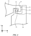
- thermally induced lens stress may be minimized using a reverse flange adhesive attachment arrangement of the type shown in FIG. 4 .
- lens 34 may be provided with a milled flange that is bonded to a surface of support 38 that faces radially outward (away from lens 34).
- adhesive 50 e.g., a soft adhesive
- An air gap such as air gap 56 is preferably present between outer peripheral edge surface 58 of lens 34 and opposing inwardly facing surface 60 of support 38, thereby ensuring that the periphery of lens 34 (surface 58) will not contact support 38 and will therefore not receive stress from support 38 even as lens 34 expands radially outward as a function of increasing operating temperature.
- a set of discretely located flexures such as the illustrative flexures of FIGS. 5 and 6 may also be used in supporting lens 34 (e.g., at three points along the perimeter of lens 34).
- lens 34 is viewed from the rear of device 10 (e.g., along the Z axis).
- One side of illustrative flexures 64 and 66 may be attached to the periphery of lens 34 using adhesive 68 and another side of flexures 64 and 66 may be attached to support 38 (e.g., using adhesive, screws or other fasteners, etc.).
- lens 34 may expand radially outward and may contract radially inward.
- flexures 64 and 66 may radially flex to accommodate the lens expansion and contraction, while accurately maintaining a desired mounting location for lens 34 within support 38.
- sealing structures e.g., ring-shaped elastomeric boots
- ring-shaped elastomeric boots may be used to help seal the periphery of lens 34 against support 38 and thereby prevent dust and moisture ingress into assembly 20.
- mount 40 may help assemblies 20 resist plastic deformation and other damage during drop events and other undesired impacts leading to excessive stress.
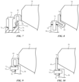
- FIGS. 7, 8, 9, and 10 are illustrative cross-sectional side views of illustrative flexures for mount 40.
- the flexures of FIGS. 7, 8, 9, and 10 may extend in a continuous ring around the periphery of lens 34, may be formed from a number of segments that extend around lens 34, or may be formed from discretely located flexures (as shown, for example, in FIGS. 5 and 6 ).
- mount 40 has a U-shaped cross-sectional shape.
- screw 70 attaches mount (flexure) 40 to support 38 and adhesive 78 attaches mount 40 to lens 34.
- a separate seal such as seal 72 may be used to seal lens 34 to support 38 and thereby help prevent moisture and dust ingress into the interior of assembly 20.
- Seal 72 may be an O-ring formed from an elastomeric gasket material, may be a ring of adhesive (e.g., pressure sensitive adhesive or other soft sealing adhesive), or may be other sealant.
- adhesive 76 may be provided at the interface between mount 40 and support 38 (e.g., epoxy or other rigid adhesive) and may be used both to attach mount 40 to support 38 and to seal mount 40 to support 38.
- the use of screws such as screw 70 of FIG. 7 to attach mount 40 to support 38 is illustrative.
- FIGS. 8, 9, and 10 may also involve the use of screws 70, adhesive 76, and/or seal 72 to attach and seal mount 40 to support 38.
- mount 40 protrudes inwardly under the outer edge of lens 34.
- screw 70 extends radially inward towards the center of lens 34.
- the flexure formed by mount 40 does not have a central bend, but rather relies on its length to ensure that sufficient flexure bending is available to accommodate radial outward expansion of lens 34 as operating temperatures rise.
- FIG. 11 shows how adhesive 78 may be dispensed to attach mount 40 to the outer edge of lens 34.
- lens 34 and mount 40 have been flipped upside down relative to the orientation of FIG. 3 .
- mount 40 may have a chamfer such as chamfer 84 that locally widens the gap between lens 34 and mount 40 to facilitate the introduction of liquid adhesive into this gap.
- Adhesive may be dispensed in liquid form in direction 82 from dispenser 80 and may then be drawn into the gap between mount 40 and lens 34 by capillary action.
- the adhesive may be cured to form adhesive 78 (e.g., using ultraviolet light curing, curing using a two-part adhesive arrangement, etc.).
- mount 40 may be provided with a stop feature such as step 86. The presence of step 86 on the inwardly facing surface of mount 40 creases a surface tension break that stops the downward flow of adhesive 78 when flowing into the joint between lens 34 and mount 40. In this way, the dispensing of adhesive 78 may be limited to a desired bonding area between mount 40 and lens 34.
- any personal user information that is gathered by device 10 may be handled using best practices. These best practices including meeting or exceeding any privacy regulations that are applicable. Opt-in and opt-out options and/or other options may be provided that allow users to control usage of their personal data.
- a head-mounted device in accordance with an aspect of the invention, includes a head-mounted housing, optical assemblies in the head-mounted housing that are configured to provide images to eye boxes, each optical assembly includes a display, a lens barrel coupled to the display, a lens, and a flexure coupled between the lens and the lens barrel.
- the lens includes a catadioptric lens.
- the flexure includes a ring with a U-shaped cross-sectional shape.
- the lens includes a first polymer and the flexure includes a second polymer that is different than the first polymer.
- the second polymer includes polyetherimide.
- the first polymer includes cyclic olefin polymer.
- the first polymer has a first coefficient of thermal expansion and the second polymer has a second coefficient of thermal expansion that is within 10% of the first coefficient of thermal expansion.
- the lens includes a catadioptric lens with a peripheral edge and the flexure includes a polymer ring with U-shaped cross-sectional shape that that extends around the peripheral edge.
- the lens barrel includes a metal lens barrel and the catadioptric lens includes polymer.
- a head-mounted device optical module includes a tube-shaped metal support having opposing first and second ends, a display coupled to the first end, a catadioptric lens having a peripheral edge, and a flexure having a first portion attached to the tube-shaped metal support at the second end, having a second portion attached to peripheral edge, and having a bend between the first and second portions.
- the flexure includes a material that with a coefficient of thermal expansion that is matched to that of the catadioptric lens within 10%.
- the head-mounted device optical module includes epoxy that attaches the second portion to the peripheral edge.
- the head-mounted device optical module includes epoxy that attaches the first portion to the tube-shaped metal support.
- the head-mounted device optical module includes a screw that attaches the first portion to the tube-shaped metal support.
- the head-mounted device optical module includes a ring-shaped seal between the tube-shaped metal support and the flexure.
- the flexure has a U-shaped cross-sectional shape and includes polymer having an elastic modulus of at least 2 GPa and a yield strength of at least 70 MPa.
- the polymer has an elongation-to-failure value of at least 30%.
- a head-mounted device in accordance with an aspect of the invention, includes a head-mounted housing, optical assemblies in the head-mounted housing that are configured to provide images to eye boxes, each optical assembly includes a display, a lens support coupled to the display, a polymer catadioptric lens, and a lens mount having at least one flexure, the lens mount is configured to attach the polymer catadioptric lens to the lens support.
- the lens support includes a metal lens support having a tubular shape and the at least one flexure includes a polymer ring with a U-shaped cross-sectional shape.
- the at least one flexure includes a set of three flexures each coupled between the lens support and the polymer catadioptric lens at a different location along a peripheral edge of the polymer catadioptric lens.
Landscapes
- Physics & Mathematics (AREA)
- General Physics & Mathematics (AREA)
- Optics & Photonics (AREA)
- Lens Barrels (AREA)
Abstract
A head-mounted device (10) may include optical assemblies (20) for presenting images to a user. The optical assemblies (20) may each have a display (32) for generating an image and a lens (34) that presents the image to a corresponding eye box (36) for viewing by a user. The optical assemblies (20) may have lens barrels (38). Each lens barrel (38) may have a first end to which a display is mounted and may have an opposing second end. A mount (40) may be used to attach the lens to the second end of the lens barrel. The mount (40) may have at least one flexure. The flexure may have a U-shaped cross-sectional shape. The mount (40) may have a ring-shaped flexure that extends around a peripheral edge of the lens (34), may have flexure segments, or may have a set of three discrete flexures located at different positions along the edge of the lens (34).
Description
- This application claims priority to
U.S. patent application No. 18/326,540, filed May 31, 2023 U.S. provisional patent application No. 63/431,394, filed December 9, 2022 - This relates generally to electronic devices, and, more particularly, to electronic devices such as head-mounted devices.
- Electronic devices such as head-mounted devices have displays that generate images and lenses that are used in presenting the images to users. Components such as lenses may be sensitive to stress, which raises challenges when mounting lenses in head-mounted devices.
- A head-mounted device may include optical assemblies for presenting images to a user. The optical assemblies may each have a display for generating an image and a lens that presents the image to a corresponding eye box for viewing by a user. The lens may be a catadioptric lens with polymer lens elements that exhibit stress-induced birefringence when subjected to excessive stress.
- The optical assemblies may have lens barrels. Each lens barrel may have a first end to which a display is mounted and may have an opposing second end. A lens mount that helps reduce stress in the lens may be used to attach the lens to the second end of the lens barrel. The mount may have at least one flexure. The flexure may have a U-shaped cross-sectional shape. The mount may have a ring-shaped flexure that extends around a peripheral edge of the lens, may have flexure segments, or may have a set of three discrete flexures located at different positions along the edge of the lens.
-
-
FIG. 1 is a diagram of an illustrative head-mounted device in accordance with an embodiment. -
FIG. 2 is a front view of an illustrative lens in accordance with embodiments. -
FIGS. 3 and4 are cross-sectional side view of peripheral portions of illustrative lenses and associated mounting structures in accordance with embodiments. -
FIGS. 5 and 6 are top views of illustrative flexures for mounting a lens in accordance with embodiments. -
FIGS. 7, 8, 9, and 10 are cross-sectional side views of additional illustrative flexure arrangements for mounting a lens in accordance with embodiments. -
FIG. 11 is a diagram showing how adhesive may be introduced into a gap between an illustrative flexure and a lens in accordance with an embodiment. - Electronic devices such as head-mounted devices may have displays for displaying images and lenses that are used in presenting the images to eye boxes for viewing by a user. The lenses may be mounted in a head-mounted device using support structures that help minimize lens stress. In an illustrative embodiment, the lenses are mounted in rigid lens supports such as metal lens barrels using lens mounts based on flexures. The flexures help prevent stress from being applied to the lenses even when the electronic devices are subjected to changes in operating temperature that cause the lenses to expand and contract.
-
FIG. 1 is a schematic diagram of an illustrative electronic device of the type that may include lenses mounted with flexures.Device 10 ofFIG. 1 may be a head-mounted device (e.g., goggles, glasses, a helmet, and/or other head-mounted device. In an illustrative configuration,device 10 is a head-mounted device such as a pair of goggles (sometimes referred to as virtual reality goggles, mixed reality goggles, augmented reality glasses, etc.). - As shown in the illustrative cross-sectional top view of
device 10 ofFIG. 1 ,device 10 may have a housing such as housing 12 (sometimes referred to as a head-mounted support structure, head-mounted housing, or head-mounted support).Housing 12 may include a front portion such as front portion 12F and a rear portion such asrear portion 12R. Whendevice 10 is worn on the head of a user,rear portion 12R rests against the face of the user and helps block stray light from reaching the eyes of the user. -
Main portion 12M ofhousing 12 may be attached tohead strap 12T.Head strap 12T may be used to help securemain portion 12 on the head and face of a user.Main portion 12M may have a rigid shell formed from housing walls of polymer, glass, metal, and/or other materials. Whenhousing 12 is being worn on the head of a user, the front ofhousing 12 may face outwardly away from the user and the rear of housing 12 (andrear portion 12R) may face towards the user. In this configuration,rear portion 12R may face the user's eyes located ineye boxes 36. -
Device 10 may have electrical and optical components that are used in displaying images toeye boxes 36 whendevice 10 is being worn. These components may include left and right optical assemblies 20 (sometimes referred to as optical modules). Eachoptical assembly 20 may have an optical assembly support 38 (sometimes referred to as a lens barrel, optical module support, or support structure).Supports 38 may have hollow tubular shapes or other suitable shapes.Optical assemblies 20 may slide laterally along guide rails to adjust optical-assembly-to-optical-assembly separation to accommodate different user interpupillary distances.Rear portion 12R may include flexible structures (e.g., a flexible polymer layer, a flexible fabric layer, etc.) so thatportion 12R can stretch to accommodate movement ofassemblies 20. - Each
assembly 20 may have adisplay 32 coupled to one end ofsupport 38 and a lens mounted to an opposing end ofsupport 38.Display 32 has an array of pixels for displaying images.Lens 34 may optionally have a removable vision correction lens for correcting user vision defects (e.g., refractive errors such as nearsightedness, farsightedness, and/or astigmatism). During operation, images displayed bydisplays 32 may be presented toeye boxes 36 throughlenses 34 for viewing by the user. - To help satisfy design constraints (e.g., low weight, compact size, wide field of view, high resolution, etc.),
lenses 34 may be catadioptric lenses. A catadioptric lens incorporates optical components such as polarizers and wave plates to create a folded optical path that can help reduce lens size. The use of these polarization-sensitive optical components may, however, makelenses 34 sensitive to performance degradation due to stress-induced birefringence effects.Lenses 34 may, as an example, include lens elements formed from polymers (for example, COC polymer (cyclic olefin copolymer) or other suitable polymers) that help minimize lens weight, but these polymers may exhibit birefringence when subjected to excess stress. - Satisfactory operation for
lenses 34 may be achieved by mountinglenses 34 using lens mounts that help isolatelenses 34 from sources of stress. In an illustrative configuration,supports 38 may be formed from strong rigid materials such as metal (e.g., aluminum, etc.). Whenoperating device 10 over wide temperature ranges (e.g., 0-50°C), there is a risk that expansion and contraction of materials inassemblies 20 and, more particularly, mismatches in the coefficient of thermal expansion between the polymer oflenses 34 and the metal ofsupports 38, can give rise to unwanted stress inlenses 34, leading to unwanted stress-induced birefringence inlenses 34. Unwanted temperature-change-induced stress may be avoided by mountinglenses 34 withinsupports 38 using lens mounts based on flexures. -
FIG. 2 is a front view of an illustrative lens fordevice 10. A shown inFIG. 2 ,lens 34 may be surrounded byflexible lens mount 40.Lens mount 40 may include one or more flexures. In an illustrative embodiment,lens mount 40 contains a ring-shaped flexure that runs around the entire perimeter oflens 34. Arrangements in whichmount 40 includes a number of separate segments (see, e.g., illustrative segment SG) each of which has a separate strip-shaped flexure segment or in whichmount 40 includes discrete flexures such as illustrative discrete flexure DL (e.g., a set of three discrete flexures attached to the periphery oflens 34 at three evenly spaced locations along the periphery) may also be used.Support 38 may be attached tomount 40 along the outer peripheral edge ofmount 40 orsupport 38 may be attached tomount 40 where support 38 overlaps mount 40 (see, e.g.,FIG. 3 ). -
FIG. 3 is a cross-sectional side view of an illustrative peripheral portion oflens 38 andmount 40 ofFIG. 2 taken alongline 42 ofFIG. 2 and viewed indirection 44. As shown inFIG. 3 , support (lens barrel) 38 may be overlapped bymount 40.Mount 40 may be formed from polymer, metal, or other material that is shaped to form a flexure. In the example ofFIG. 3 , mount 40 is a ring-shaped flexure with a U-shaped cross section that runs along the ring-shaped peripheral edge oflens 34. First portion 40-1 of the flexure is attached to the peripheral edge oflens 34 with a first ring of adhesive 50 and second portion 40-2 of the flexure is attached to support 38 with a second ring of adhesive 52. Bend 40-3 runs alongmount 40 between portions 40-1 and 4-2 and allows mount 40 to flex. For example, portion 40-1 may move radially outwardly towards portion 40-2 whenlens 34 expands radially due to an increase in operating temperature. The metal ofsupport 38 has a significantly lower coefficient of thermal expansion than the polymer oflens 34, but is separated by an air gap from the edge oflens 34, so thatlens 34 can expand radially outwardly without contactingsupport 38 and is therefore not stressed due to pressure from contact withsupport 38. -
Mount 40 may, if desired, be formed from a material such as polyetherimide (PEI) or other rigid polymer that exhibits a high yield strength and a high elongation-to-failure value. The elastic modulus of thematerial forming mount 40 may be, for example, at least 1.5 GPa, at least 2 GPa, or at least 3 GPa, as examples. The high strength and high rigidity of thematerial forming mount 40 helps mount 40 accurately holdlens 34 in place. The material ofmount 40 may exhibit a yield strength (e.g., at least 30 MPa, at least 70 MPa, or at least 100 MPa), so thatmount 40 exhibits a good yield-strength-to-stiffness ratio. To providemount 40 with satisfactory durability, it may be desirable for the material of mount to have an elongation-to-failure value of at least 25%, at least 35%, or at least 40%. To ensure satisfactory attachment ofmount 40 with adhesive 52 and 50, the material ofmount 40 preferably also exhibits satisfactory compatibility (bond strength) withadhesives Adhesives mount 40 preferably forms satisfactory bonds with epoxy. The coefficient of thermal expansion of the material ofmount 40 may be matched (e.g., within 20%, within 10%, within 5%, or within 2%) to the coefficient of thermal expansion of the material oflens 34. In this way, lens stress can be avoided that might otherwise be imposed bymount 40 onlens 34 if, for example, the perimeter ofmount 40 were to expand less quickly than the perimeter oflens 34 as a function of increasing operating temperature and thereby constrain the expansion oflens 34. Other types of materials may be used in formingmount 40, if desired. The use of polyetherimide that is matched to the polymer oflens 34 in its coefficient of thermal expansion and that exhibits high yield strength and high elongation-to-failure values is illustrative. - If desired, thermally induced lens stress may be minimized using a reverse flange adhesive attachment arrangement of the type shown in
FIG. 4 . With this type of arrangement,lens 34 may be provided with a milled flange that is bonded to a surface ofsupport 38 that faces radially outward (away from lens 34). As shown inFIG. 4 , adhesive 50 (e.g., a soft adhesive) may be used to attach outwardly facingsurface 53 ofsupport 38 to opposing inwardly faced milledflange surface 54 oflens 34. An air gap such asair gap 56 is preferably present between outerperipheral edge surface 58 oflens 34 and opposing inwardly facingsurface 60 ofsupport 38, thereby ensuring that the periphery of lens 34 (surface 58) will not contactsupport 38 and will therefore not receive stress fromsupport 38 even aslens 34 expands radially outward as a function of increasing operating temperature. - If desired a set of discretely located flexures such as the illustrative flexures of
FIGS. 5 and 6 may also be used in supporting lens 34 (e.g., at three points along the perimeter of lens 34). In the examples ofFIG. 5 and 6 ,lens 34 is viewed from the rear of device 10 (e.g., along the Z axis). One side ofillustrative flexures lens 34 usingadhesive 68 and another side offlexures lens 34 may expand radially outward and may contract radially inward. With the flexure arrangements ofFIGS. 5 and 6 ,flexures lens 34 withinsupport 38. In arrangements in with flexures are located at discrete locations around the periphery of lens 34 (e.g., three discrete locations), sealing structures (e.g., ring-shaped elastomeric boots) may be used to help seal the periphery oflens 34 againstsupport 38 and thereby prevent dust and moisture ingress intoassembly 20. As with the ring-shaped flexure ofFIGS. 2 and 3 , the discrete flexures ofFIG. 5 and 6 may be used to maintainlens 34 in a satisfactory position (without significant lateral shifting in X and Y position and without significant tilt away from the Z axis) while flexing to accommodate expansion and contraction due to temperature changes. The strength ofmount 40 may helpassemblies 20 resist plastic deformation and other damage during drop events and other undesired impacts leading to excessive stress. -
FIGS. 7, 8, 9, and 10 are illustrative cross-sectional side views of illustrative flexures formount 40. The flexures ofFIGS. 7, 8, 9, and 10 may extend in a continuous ring around the periphery oflens 34, may be formed from a number of segments that extend aroundlens 34, or may be formed from discretely located flexures (as shown, for example, inFIGS. 5 and 6 ). In the arrangements ofFIGS. 7, 8, and 9 , mount 40 has a U-shaped cross-sectional shape. - In the example of
FIG. 7 , screw 70 attaches mount (flexure) 40 to support 38 and adhesive 78 attachesmount 40 tolens 34. When using a screw such asscrew 70 to attachmount 40 to support 38 instead of adhesive, a separate seal such asseal 72 may be used to seallens 34 to support 38 and thereby help prevent moisture and dust ingress into the interior ofassembly 20.Seal 72 may be an O-ring formed from an elastomeric gasket material, may be a ring of adhesive (e.g., pressure sensitive adhesive or other soft sealing adhesive), or may be other sealant. If desired, adhesive 76 may be provided at the interface betweenmount 40 and support 38 (e.g., epoxy or other rigid adhesive) and may be used both to attachmount 40 to support 38 and to sealmount 40 to support 38. The use of screws such asscrew 70 ofFIG. 7 to attachmount 40 to support 38 is illustrative. - The illustrative configurations of
FIGS. 8, 9, and 10 may also involve the use ofscrews 70, adhesive 76, and/or seal 72 to attach and sealmount 40 to support 38. In the example ofFIG. 8 , mount 40 protrudes inwardly under the outer edge oflens 34. In the example ofFIG. 9 , screw 70 extends radially inward towards the center oflens 34. In the example ofFIG. 10 , the flexure formed bymount 40 does not have a central bend, but rather relies on its length to ensure that sufficient flexure bending is available to accommodate radial outward expansion oflens 34 as operating temperatures rise. - The diagram of
FIG. 11 shows how adhesive 78 may be dispensed to attachmount 40 to the outer edge oflens 34. In the example ofFIG. 11 ,lens 34 and mount 40 have been flipped upside down relative to the orientation ofFIG. 3 . As shown inFIG. 11 , mount 40 may have a chamfer such aschamfer 84 that locally widens the gap betweenlens 34 and mount 40 to facilitate the introduction of liquid adhesive into this gap. Adhesive may be dispensed in liquid form indirection 82 fromdispenser 80 and may then be drawn into the gap betweenmount 40 andlens 34 by capillary action. After the liquid adhesive material has been drawn into the gap, the adhesive may be cured to form adhesive 78 (e.g., using ultraviolet light curing, curing using a two-part adhesive arrangement, etc.). To help control the downward progress of adhesive 78 while adhesive 78 is liquid, mount 40 may be provided with a stop feature such asstep 86. The presence ofstep 86 on the inwardly facing surface ofmount 40 creases a surface tension break that stops the downward flow of adhesive 78 when flowing into the joint betweenlens 34 andmount 40. In this way, the dispensing of adhesive 78 may be limited to a desired bonding area betweenmount 40 andlens 34. - To help protect the privacy of users, any personal user information that is gathered by
device 10 may be handled using best practices. These best practices including meeting or exceeding any privacy regulations that are applicable. Opt-in and opt-out options and/or other options may be provided that allow users to control usage of their personal data. - In accordance with an aspect of the invention, a head-mounted device is provided that includes a head-mounted housing, optical assemblies in the head-mounted housing that are configured to provide images to eye boxes, each optical assembly includes a display, a lens barrel coupled to the display, a lens, and a flexure coupled between the lens and the lens barrel.
- Preferably, the lens includes a catadioptric lens.
- Preferably, the flexure includes a ring with a U-shaped cross-sectional shape.
- Preferably, the lens includes a first polymer and the flexure includes a second polymer that is different than the first polymer.
- Preferably, the second polymer includes polyetherimide.
- Preferably, the first polymer includes cyclic olefin polymer.
- Preferably, the first polymer has a first coefficient of thermal expansion and the second polymer has a second coefficient of thermal expansion that is within 10% of the first coefficient of thermal expansion.
- Preferably, the lens includes a catadioptric lens with a peripheral edge and the flexure includes a polymer ring with U-shaped cross-sectional shape that that extends around the peripheral edge.
- Preferably, the lens barrel includes a metal lens barrel and the catadioptric lens includes polymer.
- In accordance with an aspect of the invention, a head-mounted device optical module is provided that includes a tube-shaped metal support having opposing first and second ends, a display coupled to the first end, a catadioptric lens having a peripheral edge, and a flexure having a first portion attached to the tube-shaped metal support at the second end, having a second portion attached to peripheral edge, and having a bend between the first and second portions.
- Preferably, the flexure includes a material that with a coefficient of thermal expansion that is matched to that of the catadioptric lens within 10%.
- Preferably, the head-mounted device optical module includes epoxy that attaches the second portion to the peripheral edge.
- Preferably, the head-mounted device optical module includes epoxy that attaches the first portion to the tube-shaped metal support.
- Preferably, the head-mounted device optical module includes a screw that attaches the first portion to the tube-shaped metal support.
- Preferably, the head-mounted device optical module includes a ring-shaped seal between the tube-shaped metal support and the flexure.
- Preferably, the flexure has a U-shaped cross-sectional shape and includes polymer having an elastic modulus of at least 2 GPa and a yield strength of at least 70 MPa.
- Preferably, the polymer has an elongation-to-failure value of at least 30%.
- In accordance with an aspect of the invention, a head-mounted device is provided that includes a head-mounted housing, optical assemblies in the head-mounted housing that are configured to provide images to eye boxes, each optical assembly includes a display, a lens support coupled to the display, a polymer catadioptric lens, and a lens mount having at least one flexure, the lens mount is configured to attach the polymer catadioptric lens to the lens support.
- Preferably, the lens support includes a metal lens support having a tubular shape and the at least one flexure includes a polymer ring with a U-shaped cross-sectional shape.
- Preferably, the at least one flexure includes a set of three flexures each coupled between the lens support and the polymer catadioptric lens at a different location along a peripheral edge of the polymer catadioptric lens.
- The foregoing is merely illustrative and various modifications can be made to the described embodiments. The foregoing embodiments may be implemented individually or in any combination.
Claims (15)
- A head-mounted device, comprising:a head-mounted housing;optical assemblies in the head-mounted housing that are configured to provide images to eye boxes, wherein each optical assembly includes:a display;a lens barrel coupled to the display;a lens; anda flexure coupled between the lens and the lens barrel.
- The head-mounted device defined in claim 1 wherein the lens comprises a catadioptric lens.
- The head-mounted device defined in claim 1 or claim 2 wherein the flexure comprises a ring with a U-shaped cross-sectional shape.
- The head-mounted device defined in any preceding claim wherein the lens comprises a first polymer and wherein the flexure comprises a second polymer that is different than the first polymer.
- The head-mounted device defined in claim 4 wherein the second polymer comprises polyetherimide.
- The head-mounted device defined in claim 4 or claim 5 wherein the first polymer comprises cyclic olefin polymer.
- The head-mounted device defined in any of claims 4 to 6 wherein the first polymer has a first coefficient of thermal expansion and wherein the second polymer has a second coefficient of thermal expansion that is within 10% of the first coefficient of thermal expansion.
- The head-mounted device defined in claim 1 wherein the lens comprises a catadioptric lens with a peripheral edge and wherein the flexure comprises a polymer ring with U-shaped cross-sectional shape that that extends around the peripheral edge.
- The head-mounted device defined in claim 8 wherein the lens barrel comprises a metal lens barrel and wherein the catadioptric lens comprises polymer.
- The head-mounted device defined in claim 1 wherein each of the optical assemblies includes:
a tube-shaped metal support having opposing first and second ends, wherein the display is coupled to the first end, the lens is a catadioptric lens having a peripheral edge, and the flexure has a first portion attached to the tube-shaped metal support at the second end, a second portion attached to the peripheral edge, and a bend between the first and second portions. - The head-mounted device defined in claim 10 further comprising epoxy that attaches the second portion to the peripheral edge.
- The head-mounted device defined in claim 10 or claim 11 further comprising epoxy that attaches the first portion to the tube-shaped metal support.
- The head-mounted device defined in any of claims 10 to 12 further comprising a screw that attaches the first portion to the tube-shaped metal support.
- The head-mounted device defined in any of claims 10 to 13 wherein the flexure has a U-shaped cross-sectional shape and comprises polymer having an elastic modulus of at least 2 GPa and a yield strength of at least 70 MPa.
- The head-mounted device defined in claim 14 wherein the polymer has an elongation-to-failure value of at least 30%.
Applications Claiming Priority (2)
| Application Number | Priority Date | Filing Date | Title |
|---|---|---|---|
| US202263431394P | 2022-12-09 | 2022-12-09 | |
| US18/326,540 US12158590B2 (en) | 2022-12-09 | 2023-05-31 | Lens mounting systems with flexures coupled to the lens |
Publications (1)
| Publication Number | Publication Date |
|---|---|
| EP4382982A1 true EP4382982A1 (en) | 2024-06-12 |
Family
ID=89122147
Family Applications (1)
| Application Number | Title | Priority Date | Filing Date |
|---|---|---|---|
| EP23214694.4A Pending EP4382982A1 (en) | 2022-12-09 | 2023-12-06 | Lens mounting systems |
Country Status (2)
| Country | Link |
|---|---|
| US (2) | US12158590B2 (en) |
| EP (1) | EP4382982A1 (en) |
Families Citing this family (1)
| Publication number | Priority date | Publication date | Assignee | Title |
|---|---|---|---|---|
| US12158590B2 (en) * | 2022-12-09 | 2024-12-03 | Apple Inc. | Lens mounting systems with flexures coupled to the lens |
Citations (4)
| Publication number | Priority date | Publication date | Assignee | Title |
|---|---|---|---|---|
| WO2000052515A1 (en) * | 1999-03-05 | 2000-09-08 | Itt Manufacturing Enterprises, Inc. | Enhanced night vision device |
| US9555589B1 (en) * | 2015-09-03 | 2017-01-31 | 3M Innovative Properties Company | Method of making optical films and stacks |
| US20200400948A1 (en) * | 2019-06-21 | 2020-12-24 | Apple Inc. | Display And Vision Correction System With Removable Lens |
| EP3910404A2 (en) * | 2020-04-20 | 2021-11-17 | Apple Inc. | Electronic devices with optical modules |
Family Cites Families (14)
| Publication number | Priority date | Publication date | Assignee | Title |
|---|---|---|---|---|
| US6625372B1 (en) * | 1999-11-15 | 2003-09-23 | Axsun Technologies, Inc. | Mounting and alignment structures for optical components |
| NL1036701A1 (en) * | 2008-04-15 | 2009-10-19 | Asml Holding Nv | Apparatus for supporting an optical element, and method of making the same. |
| JP6310072B2 (en) * | 2013-06-26 | 2018-04-11 | ネクシスビジョン, インコーポレイテッド | Contact lenses for refractive correction |
| JP6638383B2 (en) | 2015-12-24 | 2020-01-29 | セイコーエプソン株式会社 | Virtual image display |
| US10268042B2 (en) | 2016-08-19 | 2019-04-23 | Seiko Epson Corporation | Head-mounted image display device |
| US10809524B2 (en) * | 2018-01-08 | 2020-10-20 | Facebook Technologies, Llc | Varifocal apparatuses, systems, and methods employing a deformable stepped lens |
| JP7155815B2 (en) | 2018-09-27 | 2022-10-19 | セイコーエプソン株式会社 | head mounted display |
| US11143838B2 (en) * | 2019-01-08 | 2021-10-12 | N2 Imaging Systems, LLC | Optical element retainers |
| US11822081B2 (en) | 2019-08-29 | 2023-11-21 | Apple Inc. | Optical module for head-mounted device |
| US11662550B1 (en) * | 2019-09-25 | 2023-05-30 | Meta Platforms Technologies, Llc | Systems and methods for varifocal adjustments |
| US11719936B2 (en) | 2020-03-23 | 2023-08-08 | Apple Inc. | Optical system for head-mounted display |
| US11892701B2 (en) | 2020-04-17 | 2024-02-06 | Apple Inc. | Lens mounting structures for head-mounted devices |
| US11936100B2 (en) * | 2022-03-16 | 2024-03-19 | Meta Platforms Technologies, Llc | System and method for 3D-printed optical lens with in-situ antenna |
| US12158590B2 (en) * | 2022-12-09 | 2024-12-03 | Apple Inc. | Lens mounting systems with flexures coupled to the lens |
-
2023
- 2023-05-31 US US18/326,540 patent/US12158590B2/en active Active
- 2023-12-06 EP EP23214694.4A patent/EP4382982A1/en active Pending
-
2024
- 2024-10-02 US US18/905,046 patent/US20250028179A1/en active Pending
Patent Citations (4)
| Publication number | Priority date | Publication date | Assignee | Title |
|---|---|---|---|---|
| WO2000052515A1 (en) * | 1999-03-05 | 2000-09-08 | Itt Manufacturing Enterprises, Inc. | Enhanced night vision device |
| US9555589B1 (en) * | 2015-09-03 | 2017-01-31 | 3M Innovative Properties Company | Method of making optical films and stacks |
| US20200400948A1 (en) * | 2019-06-21 | 2020-12-24 | Apple Inc. | Display And Vision Correction System With Removable Lens |
| EP3910404A2 (en) * | 2020-04-20 | 2021-11-17 | Apple Inc. | Electronic devices with optical modules |
Also Published As
| Publication number | Publication date |
|---|---|
| US20250028179A1 (en) | 2025-01-23 |
| US20240192505A1 (en) | 2024-06-13 |
| US12158590B2 (en) | 2024-12-03 |
Similar Documents
| Publication | Publication Date | Title |
|---|---|---|
| US12111471B2 (en) | Free-form prism-lens group and near-eye display apparatus | |
| US11243398B2 (en) | Optical device for a head-mounted display, and head-mounted device incorporating it for augmented reality | |
| JP7268437B2 (en) | virtual image display | |
| JP2017181819A (en) | On-vehicle device including curved display | |
| CN106019585B (en) | head mounted display | |
| CN107924058B (en) | Optical device adapted to a wearer | |
| US20250028179A1 (en) | Lens Mounting Systems | |
| US7262890B2 (en) | Observation optical system | |
| US6768592B2 (en) | Optical combiners | |
| JP2018014620A (en) | Virtual image display device | |
| JP2014174367A (en) | Virtual image display device | |
| CN118169826A (en) | Lens mounting system | |
| TW202238179A (en) | Liquid lens with gravity sag correction | |
| US20220099871A1 (en) | Diffractive optical member and virtual image display device | |
| CN117518498A (en) | Smart glasses and installation methods | |
| US20250271733A1 (en) | Optical apparatus | |
| US12271003B2 (en) | Image display device | |
| KR20160005557A (en) | Optical apparatus and HMD having the same | |
| US12405477B2 (en) | Image display device | |
| US12399373B2 (en) | Image display device | |
| JPH11296095A (en) | Video display device | |
| JP2023102601A (en) | optical equipment | |
| CN121784969A (en) | Virtual image display device and optical unit | |
| JP2025080044A (en) | Phase difference optical element and method for producing phase difference optical element | |
| GB2394067A (en) | Viewing device with reticle |
Legal Events
| Date | Code | Title | Description |
|---|---|---|---|
| PUAI | Public reference made under article 153(3) epc to a published international application that has entered the european phase |
Free format text: ORIGINAL CODE: 0009012 |
|
| STAA | Information on the status of an ep patent application or granted ep patent |
Free format text: STATUS: REQUEST FOR EXAMINATION WAS MADE |
|
| 17P | Request for examination filed |
Effective date: 20231206 |
|
| AK | Designated contracting states |
Kind code of ref document: A1 Designated state(s): AL AT BE BG CH CY CZ DE DK EE ES FI FR GB GR HR HU IE IS IT LI LT LU LV MC ME MK MT NL NO PL PT RO RS SE SI SK SM TR |