EP4382932A1 - Battery testing device and battery testing system - Google Patents
Battery testing device and battery testing system Download PDFInfo
- Publication number
- EP4382932A1 EP4382932A1 EP22853339.4A EP22853339A EP4382932A1 EP 4382932 A1 EP4382932 A1 EP 4382932A1 EP 22853339 A EP22853339 A EP 22853339A EP 4382932 A1 EP4382932 A1 EP 4382932A1
- Authority
- EP
- European Patent Office
- Prior art keywords
- battery
- battery cells
- battery testing
- connecting unit
- testing apparatus
- Prior art date
- Legal status (The legal status is an assumption and is not a legal conclusion. Google has not performed a legal analysis and makes no representation as to the accuracy of the status listed.)
- Pending
Links
Images


Classifications
-
- G—PHYSICS
- G01—MEASURING; TESTING
- G01R—MEASURING ELECTRIC VARIABLES; MEASURING MAGNETIC VARIABLES
- G01R31/00—Arrangements for testing electric properties; Arrangements for locating electric faults; Arrangements for electrical testing characterised by what is being tested not provided for elsewhere
- G01R31/36—Arrangements for testing, measuring or monitoring the electrical condition of accumulators or electric batteries, e.g. capacity or state of charge [SoC]
- G01R31/367—Software therefor, e.g. for battery testing using modelling or look-up tables
-
- G—PHYSICS
- G01—MEASURING; TESTING
- G01R—MEASURING ELECTRIC VARIABLES; MEASURING MAGNETIC VARIABLES
- G01R31/00—Arrangements for testing electric properties; Arrangements for locating electric faults; Arrangements for electrical testing characterised by what is being tested not provided for elsewhere
- G01R31/28—Testing of electronic circuits, e.g. by signal tracer
- G01R31/282—Testing of electronic circuits specially adapted for particular applications not provided for elsewhere
-
- G—PHYSICS
- G01—MEASURING; TESTING
- G01R—MEASURING ELECTRIC VARIABLES; MEASURING MAGNETIC VARIABLES
- G01R31/00—Arrangements for testing electric properties; Arrangements for locating electric faults; Arrangements for electrical testing characterised by what is being tested not provided for elsewhere
- G01R31/36—Arrangements for testing, measuring or monitoring the electrical condition of accumulators or electric batteries, e.g. capacity or state of charge [SoC]
- G01R31/3644—Constructional arrangements
- G01R31/3648—Constructional arrangements comprising digital calculation means, e.g. for performing an algorithm
-
- G—PHYSICS
- G01—MEASURING; TESTING
- G01R—MEASURING ELECTRIC VARIABLES; MEASURING MAGNETIC VARIABLES
- G01R31/00—Arrangements for testing electric properties; Arrangements for locating electric faults; Arrangements for electrical testing characterised by what is being tested not provided for elsewhere
- G01R31/36—Arrangements for testing, measuring or monitoring the electrical condition of accumulators or electric batteries, e.g. capacity or state of charge [SoC]
- G01R31/371—Arrangements for testing, measuring or monitoring the electrical condition of accumulators or electric batteries, e.g. capacity or state of charge [SoC] with remote indication, e.g. on external chargers
-
- G—PHYSICS
- G01—MEASURING; TESTING
- G01R—MEASURING ELECTRIC VARIABLES; MEASURING MAGNETIC VARIABLES
- G01R31/00—Arrangements for testing electric properties; Arrangements for locating electric faults; Arrangements for electrical testing characterised by what is being tested not provided for elsewhere
- G01R31/36—Arrangements for testing, measuring or monitoring the electrical condition of accumulators or electric batteries, e.g. capacity or state of charge [SoC]
- G01R31/382—Arrangements for monitoring battery or accumulator variables, e.g. SoC
- G01R31/3842—Arrangements for monitoring battery or accumulator variables, e.g. SoC combining voltage and current measurements
-
- G—PHYSICS
- G01—MEASURING; TESTING
- G01R—MEASURING ELECTRIC VARIABLES; MEASURING MAGNETIC VARIABLES
- G01R31/00—Arrangements for testing electric properties; Arrangements for locating electric faults; Arrangements for electrical testing characterised by what is being tested not provided for elsewhere
- G01R31/36—Arrangements for testing, measuring or monitoring the electrical condition of accumulators or electric batteries, e.g. capacity or state of charge [SoC]
- G01R31/385—Arrangements for measuring battery or accumulator variables
- G01R31/3865—Arrangements for measuring battery or accumulator variables related to manufacture, e.g. testing after manufacture
-
- G—PHYSICS
- G01—MEASURING; TESTING
- G01R—MEASURING ELECTRIC VARIABLES; MEASURING MAGNETIC VARIABLES
- G01R31/00—Arrangements for testing electric properties; Arrangements for locating electric faults; Arrangements for electrical testing characterised by what is being tested not provided for elsewhere
- G01R31/36—Arrangements for testing, measuring or monitoring the electrical condition of accumulators or electric batteries, e.g. capacity or state of charge [SoC]
- G01R31/392—Determining battery ageing or deterioration, e.g. state of health
-
- H—ELECTRICITY
- H01—ELECTRIC ELEMENTS
- H01M—PROCESSES OR MEANS, e.g. BATTERIES, FOR THE DIRECT CONVERSION OF CHEMICAL ENERGY INTO ELECTRICAL ENERGY
- H01M10/00—Secondary cells; Manufacture thereof
- H01M10/42—Methods or arrangements for servicing or maintenance of secondary cells or secondary half-cells
- H01M10/4285—Testing apparatus
-
- H—ELECTRICITY
- H01—ELECTRIC ELEMENTS
- H01M—PROCESSES OR MEANS, e.g. BATTERIES, FOR THE DIRECT CONVERSION OF CHEMICAL ENERGY INTO ELECTRICAL ENERGY
- H01M10/00—Secondary cells; Manufacture thereof
- H01M10/42—Methods or arrangements for servicing or maintenance of secondary cells or secondary half-cells
- H01M10/44—Methods for charging or discharging
- H01M10/441—Methods for charging or discharging for several batteries or cells simultaneously or sequentially
-
- H—ELECTRICITY
- H01—ELECTRIC ELEMENTS
- H01M—PROCESSES OR MEANS, e.g. BATTERIES, FOR THE DIRECT CONVERSION OF CHEMICAL ENERGY INTO ELECTRICAL ENERGY
- H01M10/00—Secondary cells; Manufacture thereof
- H01M10/42—Methods or arrangements for servicing or maintenance of secondary cells or secondary half-cells
- H01M10/48—Accumulators combined with arrangements for measuring, testing or indicating the condition of cells, e.g. the level or density of the electrolyte
- H01M10/482—Accumulators combined with arrangements for measuring, testing or indicating the condition of cells, e.g. the level or density of the electrolyte for several batteries or cells simultaneously or sequentially
-
- H—ELECTRICITY
- H01—ELECTRIC ELEMENTS
- H01M—PROCESSES OR MEANS, e.g. BATTERIES, FOR THE DIRECT CONVERSION OF CHEMICAL ENERGY INTO ELECTRICAL ENERGY
- H01M10/00—Secondary cells; Manufacture thereof
- H01M10/42—Methods or arrangements for servicing or maintenance of secondary cells or secondary half-cells
- H01M10/48—Accumulators combined with arrangements for measuring, testing or indicating the condition of cells, e.g. the level or density of the electrolyte
- H01M10/486—Accumulators combined with arrangements for measuring, testing or indicating the condition of cells, e.g. the level or density of the electrolyte for measuring temperature
-
- H—ELECTRICITY
- H02—GENERATION; CONVERSION OR DISTRIBUTION OF ELECTRIC POWER
- H02J—ELECTRIC POWER NETWORKS; CIRCUIT ARRANGEMENTS OR SYSTEMS FOR SUPPLYING OR DISTRIBUTING ELECTRIC POWER; SYSTEMS FOR STORING ELECTRIC ENERGY
- H02J7/00—Circuit arrangements for charging or discharging batteries or for supplying loads from batteries
- H02J7/70—Circuit arrangements for charging or discharging batteries or for supplying loads from batteries characterised by the mechanical construction
- H02J7/751—Circuit arrangements for charging or discharging batteries or for supplying loads from batteries characterised by the mechanical construction concerning the insertion or the connection of the batteries
-
- G—PHYSICS
- G01—MEASURING; TESTING
- G01R—MEASURING ELECTRIC VARIABLES; MEASURING MAGNETIC VARIABLES
- G01R31/00—Arrangements for testing electric properties; Arrangements for locating electric faults; Arrangements for electrical testing characterised by what is being tested not provided for elsewhere
- G01R31/36—Arrangements for testing, measuring or monitoring the electrical condition of accumulators or electric batteries, e.g. capacity or state of charge [SoC]
- G01R31/389—Measuring internal impedance, internal conductance or related variables
-
- Y—GENERAL TAGGING OF NEW TECHNOLOGICAL DEVELOPMENTS; GENERAL TAGGING OF CROSS-SECTIONAL TECHNOLOGIES SPANNING OVER SEVERAL SECTIONS OF THE IPC; TECHNICAL SUBJECTS COVERED BY FORMER USPC CROSS-REFERENCE ART COLLECTIONS [XRACs] AND DIGESTS
- Y02—TECHNOLOGIES OR APPLICATIONS FOR MITIGATION OR ADAPTATION AGAINST CLIMATE CHANGE
- Y02E—REDUCTION OF GREENHOUSE GAS [GHG] EMISSIONS, RELATED TO ENERGY GENERATION, TRANSMISSION OR DISTRIBUTION
- Y02E60/00—Enabling technologies; Technologies with a potential or indirect contribution to GHG emissions mitigation
- Y02E60/10—Energy storage using batteries
Definitions
- Embodiments disclosed herein relate to a battery testing apparatus and a battery testing system.
- An electric vehicle is supplied with electricity from outside to charge a battery cell, and then a motor is driven by a voltage charged in the battery cell to obtain power.
- Battery cells of electric vehicles repeatedly expand and contract due to chemical reactions that occur in a process of charging and discharging electricity, such that a risk of explosion may exist.
- the stability of a battery cell has to be verified through various tests in production.
- Atypical battery cell testing system performs various tests while loading a battery cell on a tray and transporting the tray with specific equipment.
- a passive battery cell testing system tests a battery for a short test time while conveying a tray, there is a problem in that a defective battery cell leaks to an assembly process and a test for the battery is difficult to perform frequently.
- Embodiments disclosed herein aim to provide a battery testing apparatus and a battery testing system capable of performing accurate and continuous tests by automatically performing a battery cell test.
- a battery testing apparatus includes a first connecting unit connected to a positive electrode of each of a plurality of battery cells, a second connecting unit connected to a negative electrode of each of the plurality of battery cells, a charging/discharging managing unit configured to charge or discharge the plurality of battery cells through the first connecting unit and the second connecting unit, and a monitoring unit configured to measure state information in at least any one of a charging state, a discharging state, and an idle state of each of the plurality of battery cells.
- the first connecting unit may include a plurality of first terminals respectively connected to positive electrodes of the plurality of battery cells
- the second connecting unit may include a plurality of second terminals respectively connected to negative electrodes of the plurality of battery cells.
- the first terminal and the second terminal may be electrically connected to the charging/discharging managing unit.
- the state information may include at least one of a voltage, a temperature, electrochemical impedance spectroscopy (EIS) data, and a self-discharging current.
- EIS electrochemical impedance spectroscopy
- the monitoring unit may be further configured to transmit the measured state information of each of the plurality of battery cells to a server.
- the server may be further configured to control an amount of charge of the plurality of battery cells.
- the server may be further configured to generate a machine learning model that determines whether the plurality of battery cells are defective, based on state information of the plurality of battery cells, measured by the battery testing apparatus.
- a battery testing system includes a battery testing apparatus including a first connecting unit connected to a positive electrode of each of a plurality of battery cells, a second connecting unit connected to a negative electrode of each of the plurality of battery cells, a charging/discharging managing unit configured to charge or discharge the plurality of battery cells through the first connecting unit and the second connecting unit, and a monitoring unit configured to measure state information in at least any one of a charging state, a discharging state, and an idle state of each of the plurality of battery cells, and a tray on which the plurality of battery cells are accommodated.
- the state information may include at least one of a voltage, a temperature, electrochemical impedance spectroscopy (EIS) data, and a self-discharging current.
- EIS electrochemical impedance spectroscopy
- the monitoring unit may be further configured to transmit the measured state information of each of the plurality of battery cells to a server.
- the server may be further configured to control an amount of charge of the plurality of battery cells.
- the battery testing system may further include a pressure forming unit configured to apply pressure to the plurality of battery cells.
- the pressure forming unit may be provided in a space formed between the plurality of battery cells accommodated in the tray.
- the pressure forming unit may be connected to a pneumatic feeder or a hydraulic feeder.
- the pneumatic feeder or the hydraulic feeder may be connected to the server through a wireless or wired network.
- a battery testing apparatus and a battery testing system may automatically perform a battery cell test to provide an accurate and continuous battery stability test.
- terms such as first, second, A, B, (a), (b), etc. may be used. These terms are used merely for distinguishing one component from another component and do not limit the component to the essence, sequence, order, etc., of the component.
- the terms used herein, including technical and scientific terms, have the same meanings as terms that are generally understood by those skilled in the art, as long as the terms are not differently defined.
- the terms defined in a generally used dictionary should be interpreted as having the same meanings as the contextual meanings of the relevant technology and should not be interpreted as having ideal or exaggerated meanings unless they are clearly defined in the present document.
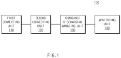
- FIG. 1 is a block diagram illustrating a configuration of a battery testing apparatus, according to an embodiment disclosed herein.
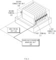
- FIG. 2 is a view for generally describing a battery testing apparatus according to an embodiment disclosed herein.
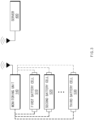
- FIG. 3 is a view for describing operations of a battery testing apparatus and a server, according to an embodiment disclosed herein.
- FIGS. 1 and 3 a configuration and an operation of a battery testing apparatus 100 will be described.
- a plurality of battery cells 510, 520, and 530 are partially illustrated in FIGS. 1 to 3 , but the plurality of battery cells may include n (n is a natural number equal to or greater than 2) battery cells, without being limited thereto.
- the plurality of battery cells 510, 520, and 530 may be a lithium ion (Li-ion) battery, an Li-ion polymer battery, a nickel-cadmium (Ni-Cd) battery, a nickel hydrogen (Ni-MH) battery, etc., and are not limited thereto.
- the battery testing apparatus 100 may include a first connecting unit 110, a second connecting unit 120, a charging/discharging managing unit 130, and a monitoring unit 140.
- the first connecting unit 110 may be connected to a first electrode of each of the plurality of battery cells 510, 520, and 530.
- a first electrode may be a positive electrode.
- the first connecting unit 110 may be implemented in the form of a gripper that holds a positive tab of each of the plurality of battery cells 510, 520, and 530.
- the first connecting unit 110 may include a plurality of first terminals 111 respectively connected to the first electrodes of the plurality of battery cells 510, 520, and 530. That is, the first connecting unit 110 may be connected to the first electrode of each of the plurality of battery cells 510, 520, and 530 through the plurality of first terminals 111.
- the plurality of first terminals 111 may be electrically connected to the charging/discharging managing unit 130 so as to be supplied with power from the charging/discharging managing unit 130.
- the second connecting unit 120 may be connected to a second electrode of each of the plurality of battery cells 510, 520, and 530.
- a second electrode may be a negative electrode.
- the second connecting unit 120 may be implemented in the form of a gripper that holds a negative tab of each of the plurality of battery cells 510, 520, and 530.
- the second connecting unit 120 may include a plurality of second terminals 121 respectively connected to the second electrodes of the plurality of battery cells 510, 520, and 530. That is, the second connecting unit 120 may be connected to the second electrode of each of the plurality of battery cells 510, 520, and 530 through the plurality of second terminals 121.
- the plurality of second terminals 121 may be electrically connected to the charging/discharging managing unit 130 so as to be supplied with power from the charging/discharging managing unit 130.
- the charging/discharging managing unit 130 may charge or discharge the plurality of battery cells 510, 520, and 530 through the first connecting unit 110 and the second connecting unit 120.
- the charging/discharging managing unit 130 may be electrically connected with the first terminal 111 and the second terminal 121 to supply power to the plurality of battery cells 510, 520, and 530.
- the charging/discharging managing unit 130 may manage a state of charge (SOC) value of each of the plurality of battery cells 510, 520, and 530 by charging or discharging each of the plurality of battery cells 510, 520, and 530.
- SOC state of charge
- the charging/discharging managing unit 130 may manage the amount of charge or discharge of each of the plurality of battery cells 510, 520, and 530 in response to a control command transmitted from a server 400.
- the monitoring unit 140 may monitor charging, discharging, remaining battery capacity, etc., of each of the plurality of battery cells 510, 520, and 530.
- the monitoring unit 140 may be understood as a battery management apparatus. More specifically, the monitoring unit 140 may measure state information of each of the plurality of battery cells 510, 520, and 530 in at least one of a charging state, a discharging state, and an idle state.
- the state information may include at least one of a voltage, a temperature, electrochemical impedance spectroscopy (EIS) data, and a self-discharging current.
- the monitoring unit 140 may measure a voltage, a current, a temperature, etc., of each of the plurality of battery cells 510, 520, and 530, and calculate a parameter indicating a state of each of the plurality of battery cells 510, 520, and 530 based on the measured voltage, current, temperature, etc. For example, the monitoring unit 140 may measure the EIS data with respect to a change in the SOC value of each of the plurality of battery cells 510, 520, and 530.
- a typical battery testing apparatus may measure required time, temperature, and voltage while repeating charging and discharging of a battery cell to evaluate whether a battery is defective. Such a battery testing method may not be able to reflect detailed characteristics of the battery.
- EIS is a battery diagnosis method using impedance measurement of the battery cell, and may detect a damaged battery cell. Impedance may be a cause that interferes with electrical conduction of an electrode when chemical reaction occurs in the battery cell. Thus, the battery testing apparatus 100 may accurately and rapidly test the battery cell based on EIS data measured by the monitoring unit 140.
- the monitoring unit 140 may transmit measured state information of each of the plurality of battery cells 510, 520, and 530 to the server 400 through a wired/wireless network.
- the monitoring unit 140 may transmit the measured state information of each of the plurality of battery cells 510, 520, and 530 to the server 400 through Bluetooth, WiFi, or ZigBee.
- the monitoring unit 140 may collect the state information of each of the plurality of battery cells 510, 520, and 530 and transmit the collected state information to the server 400. That is, the monitoring unit 140 may perform serial communication with each of the plurality of battery cells 510, 520, and 530 and transmit the state information of each of the plurality of battery cells 510, 520, and 530 to the server 400.
- the monitoring unit 140 may measure the EIS data with respect to the SOC value of each of the plurality of battery cells 510, 520, and 530 and transmit the measured EIS data to the server 400.
- the server 400 may be defined as a controller that receives the state information of each of the plurality of battery cells 510, 520, and 530 and determines whether each of the plurality of battery cells 510, 520, and 530 is defective.
- the server 400 may control the amount of charge of the plurality of battery cells 510, 520, and 530. More specifically, the server 400 may control the charging/discharging managing unit 130 to supply, maintain, or block power supplied to each of the plurality of battery cells 510, 520, and 530, thereby controlling the amount of charge (SOC) of the plurality of battery cells 510, 520, and 530.
- SOC amount of charge
- the server 400 may control the amount of charge of the plurality of battery cells 510, 520, and 530 based on a target SOC value.
- the target SOC value may be defined as an SOC value in which defective battery cells are most often detected.
- the server 400 may control the charging/discharging managing unit 130 to control the amount of charge of the plurality of battery cells 510, 520, and 530 as the target SOC value.
- the server 400 may receive the EIS data measured through the monitoring unit 140 and analyze a change in an impedance of a battery cell to detect a defective battery cell. For example, a battery cell damaged due to discharge, a battery cell damaged due to overheat, or a battery cell damaged due to short may derive a unique impedance change graph. Thus, the server 400 may compare the EIS data measured through the monitoring unit 140 with a previously stored impedance change graph of a damaged battery cell to detect a defective battery cell.
- the server 400 may be generate a machine learning model for determining whether the plurality of battery cells 510, 520, and 530 are defective, based on the state information of the plurality of battery cells 510, 520, and 530, measured by the battery testing apparatus 100.
- the server 400 may be generate a machine learning model for detecting a defective battery cell, based on the EIS data of the plurality of battery cells 510, 520, and 530, measured by the battery testing apparatus 100.
- the server 400 may determine whether the plurality of battery cells 510, 520, and 530 measured through the monitoring unit 140 are defective, by using the generated machine learning model.
- the battery testing apparatus 100 may provide a battery test for accurate and continuous detection of a defective battery cell by automatically performing a battery cell test.
- the battery testing apparatus 100 may simulate various battery test environments through the monitoring unit to simulate an actual battery manufacturing or battery module assembly processing environment.
- the battery testing apparatus 100 may measure the state of the battery cell in real time to immediately determine whether the battery cell is defective. Therefore, the battery testing apparatus 100 may prevent the defective battery cell from leaking to the battery module assembly process in a battery transport process or test mid-process.
- the battery testing apparatus 100 may enable charging and discharging required for activation of the battery cell in a place where a battery is stored, without moving the battery cell with separate equipment after manufacturing of the battery cell, thereby improving the efficiency of the battery test.
- FIG. 4 is a block diagram illustrating a configuration of a battery testing system according to an embodiment disclosed herein.
- FIG. 5 is a view for generally describing a battery testing system according to an embodiment disclosed herein.
- FIG. 6 is a view for describing operations of a battery testing system and a pressure forming unit, according to an embodiment disclosed herein.
- a battery testing system 1000 may include the battery testing apparatus 100 and a tray 200.
- FIGS. 4 and 6 a configuration and an operation of the battery testing system 1000 will be described.
- the battery testing system 1000 may include the battery testing apparatus 100 and the tray 200.
- the battery testing apparatus 100 may be substantially the same as the battery testing apparatus 100 described with reference to FIGS. 1 to 3 , and thus will be briefly described to avoid redundant description.
- the battery testing apparatus 100 may include the first connecting unit 110, the second connecting unit 120, the charging/discharging managing unit 130, and the monitoring unit 140.
- the first connecting unit 110 may be connected to the first electrode of each of the plurality of battery cells 510, 520, and 530.
- the first electrode may be a positive electrode.
- the first connecting unit 110 may include the plurality of first terminals 111 respectively connected to the first electrodes of the plurality of battery cells 510, 520, and 530.
- the second connecting unit 120 may be connected to the second electrode of each of the plurality of battery cells 510, 520, and 530.
- the second electrode may be a negative electrode.
- the second connecting unit 120 may include the plurality of second terminals 121 respectively connected to the second electrodes of the plurality of battery cells 510, 520, and 530.
- the charging/discharging managing unit 130 may charge or discharge the plurality of battery cells 510, 520, and 530 through the first connecting unit 110 and the second connecting unit 120.
- the monitoring unit 140 may monitor charging, discharging, remaining battery capacity, etc., of each of the plurality of battery cells 510, 520, and 530. More specifically, the monitoring unit 140 may measure state information of each of the plurality of battery cells 510, 520, and 530 in at least one of a charging state, a discharging state, and an idle state.
- the monitoring unit 140 may transmit the measured state information of each of the plurality of battery cells 510, 520, and 530 to the server 400 through a wired/wireless network.
- the server 400 may be defined as a controller that receives the state information of each of the plurality of battery cells 510, 520, and 530 and determines whether each of the plurality of battery cells 510, 520, and 530 is defective.
- the server 400 may control the amount of charge of the plurality of battery cells 510, 520, and 530.
- the server 400 may be generate a machine learning model for determining whether the plurality of battery cells 510, 520, and 530 are defective, based on the state information of the plurality of battery cells 510, 520, and 530, measured by the battery testing apparatus 100.
- the tray 200 may be defined as a case in which each of the plurality of battery cells 510, 520, and 530 is accommodated.
- the tray 200 may be loaded with the plurality of battery cells 510, 520, and 530 to provide a battery test environment in which the plurality of battery cells 510, 520, and 530 perform an auto battery test without being moved.
- the plurality of battery cells 510, 520, and 530 loaded on the tray 200 may be connected in parallel such that the charging/discharging managing unit 130 may collectively control the amount of charge of the plurality of battery cells 510, 520, and 530.
- the first connecting unit 110 or the second connecting unit 120 may be attached to a side of the tray 200.
- the tray 200 may be electrically connected to the monitoring unit 140.
- the battery testing system 1000 may further include a pressure forming unit 300 that applies pressure to the plurality of battery cells 510, 520, and 530.
- the pressure forming unit 300 may be defined as pressure forming tool that provides pressure to the plurality of battery cells 510, 520, and 530.
- the battery testing system 1000 may further include the pressure forming unit 300 that is pressure forming instrument for simulating a module assembly process to detect in advance a defect of the plurality of battery cells 510, 520, and 530, which may be expressed in a battery module assembly process.
- the pressure forming unit 300 that is pressure forming instrument for simulating a module assembly process to detect in advance a defect of the plurality of battery cells 510, 520, and 530, which may be expressed in a battery module assembly process.
- the pressure forming unit 300 may be provided in a space formed between the plurality of battery cells 510, 520, and 530 accommodated in the tray 200. More specifically, in the tray 200 where the plurality of battery cells 510, 520, and 530 are respectively accommodated, the pressure forming unit 300 may be mounted on a space between the plurality of battery cells 510, 520, and 530 to provide pressure to each of the plurality of battery cells 510, 520, and 530.
- the pressure forming unit 300 may be connected to a pressure former 310 to provide pressure to each of the plurality of battery cells 510, 520, and 530.
- the pressure former 310 may include, for example, a pneumatic feeder 311 or a hydraulic feeder 312.
- the pressure forming unit 300 may be connected to the pneumatic feeder 311 to provide air pressure to the plurality of battery cells 510, 520, and 530.
- the pressure forming unit 300 may be connected to the hydraulic feeder 312 to provide air pressure to the plurality of battery cells 510, 520, and 530.
- the pneumatic feeder 311 or the hydraulic feeder 312 may be connected to the server 400 through a wired or wireless network.
- the server 400 may control the pressure former 310 to provide pressure to the plurality of battery cells 510, 520, and 530.
- the server 400 may control the charging/discharging managing unit 130 to repeat charging and discharging of the plurality of battery cells 510, 520, and 530 to which pressure is applied.
- the server 400 may control the charging/discharging managing unit 130 to set a voltage of the plurality of battery cells 510, 520, and 530 to which pressure is applied to a voltage corresponding to the target SOC value. That is, the server 400 may adjust the amount of charge (SOC) of the plurality of battery cells 510, 520, and 530 to which pressure is applied to the target SOC value, thereby setting the voltage of the plurality of battery cells 510, 520, and 530 to which pressure is applied to the voltage corresponding to the target SOC value.
- SOC amount of charge
- the server 400 may control the monitoring unit 140 to measure a self-discharge voltage or current of the plurality of battery cells 510, 520, and 530 to which pressure is applied, thereby detecting a defective battery cell.
- the server 400 may compare the self-discharge voltage or current of the plurality of battery cells 510, 520, and 530 to which pressure is applied with previously stored self-discharge voltage or current data of a normal battery cell to detect a defective battery cell.
Landscapes
- Engineering & Computer Science (AREA)
- Manufacturing & Machinery (AREA)
- Chemical & Material Sciences (AREA)
- Chemical Kinetics & Catalysis (AREA)
- Electrochemistry (AREA)
- General Chemical & Material Sciences (AREA)
- Physics & Mathematics (AREA)
- General Physics & Mathematics (AREA)
- General Engineering & Computer Science (AREA)
- Power Engineering (AREA)
- Secondary Cells (AREA)
- Charge And Discharge Circuits For Batteries Or The Like (AREA)
Abstract
Description
- This application claims priority to and the benefit of
Korean Patent Application No. 10-2021-0102178 filed in the Korean Intellectual Property Office on August 3, 2021 - Embodiments disclosed herein relate to a battery testing apparatus and a battery testing system.
- An electric vehicle is supplied with electricity from outside to charge a battery cell, and then a motor is driven by a voltage charged in the battery cell to obtain power. Battery cells of electric vehicles repeatedly expand and contract due to chemical reactions that occur in a process of charging and discharging electricity, such that a risk of explosion may exist. Thus, the stability of a battery cell has to be verified through various tests in production.
- Atypical battery cell testing system performs various tests while loading a battery cell on a tray and transporting the tray with specific equipment. However, since such a passive battery cell testing system tests a battery for a short test time while conveying a tray, there is a problem in that a defective battery cell leaks to an assembly process and a test for the battery is difficult to perform frequently.
- Embodiments disclosed herein aim to provide a battery testing apparatus and a battery testing system capable of performing accurate and continuous tests by automatically performing a battery cell test.
- Technical problems of the embodiments disclosed herein are not limited to the above-described technical problems, and other unmentioned technical problems would be clearly understood by one of ordinary skill in the art from the following description.
- A battery testing apparatus according to an embodiment disclosed herein includes a first connecting unit connected to a positive electrode of each of a plurality of battery cells, a second connecting unit connected to a negative electrode of each of the plurality of battery cells, a charging/discharging managing unit configured to charge or discharge the plurality of battery cells through the first connecting unit and the second connecting unit, and a monitoring unit configured to measure state information in at least any one of a charging state, a discharging state, and an idle state of each of the plurality of battery cells.
- According to an embodiment, the first connecting unit may include a plurality of first terminals respectively connected to positive electrodes of the plurality of battery cells, and the second connecting unit may include a plurality of second terminals respectively connected to negative electrodes of the plurality of battery cells.
- According to an embodiment, the first terminal and the second terminal may be electrically connected to the charging/discharging managing unit.
- According to an embodiment, the state information may include at least one of a voltage, a temperature, electrochemical impedance spectroscopy (EIS) data, and a self-discharging current.
- According to an embodiment, the monitoring unit may be further configured to transmit the measured state information of each of the plurality of battery cells to a server.
- According to an embodiment, the server may be further configured to control an amount of charge of the plurality of battery cells.
- According to an embodiment, the server may be further configured to generate a machine learning model that determines whether the plurality of battery cells are defective, based on state information of the plurality of battery cells, measured by the battery testing apparatus.
- A battery testing system according to an embodiment disclosed herein includes a battery testing apparatus including a first connecting unit connected to a positive electrode of each of a plurality of battery cells, a second connecting unit connected to a negative electrode of each of the plurality of battery cells, a charging/discharging managing unit configured to charge or discharge the plurality of battery cells through the first connecting unit and the second connecting unit, and a monitoring unit configured to measure state information in at least any one of a charging state, a discharging state, and an idle state of each of the plurality of battery cells, and a tray on which the plurality of battery cells are accommodated.
- According to an embodiment, the state information may include at least one of a voltage, a temperature, electrochemical impedance spectroscopy (EIS) data, and a self-discharging current.
- According to an embodiment, the monitoring unit may be further configured to transmit the measured state information of each of the plurality of battery cells to a server.
- According to an embodiment, the server may be further configured to control an amount of charge of the plurality of battery cells.
- According to an embodiment, the battery testing system may further include a pressure forming unit configured to apply pressure to the plurality of battery cells.
- According to an embodiment, the pressure forming unit may be provided in a space formed between the plurality of battery cells accommodated in the tray.
- According to an embodiment, the pressure forming unit may be connected to a pneumatic feeder or a hydraulic feeder.
- According to an embodiment, the pneumatic feeder or the hydraulic feeder may be connected to the server through a wireless or wired network.
- A battery testing apparatus and a battery testing system according to an embodiment disclosed herein may automatically perform a battery cell test to provide an accurate and continuous battery stability test.
-
-
FIG. 1 is a block diagram illustrating a configuration of a battery testing apparatus, according to an embodiment disclosed herein. -
FIG. 2 is a view for generally describing a battery testing apparatus according to an embodiment disclosed herein. -
FIG. 3 is a view for describing operations of a battery testing apparatus and a server, according to an embodiment disclosed herein. -
FIG. 4 is a block diagram illustrating a configuration of a battery testing system according to an embodiment disclosed herein. -
FIG. 5 is a view for generally describing a battery testing system according to an embodiment disclosed herein. -
FIG. 6 is a view for describing operations of a battery testing system and a pressure forming unit, according to an embodiment disclosed herein. - Hereinafter, some embodiments disclosed in this document will be described in detail with reference to the exemplary drawings. In adding reference numerals to components of each drawing, it should be noted that the same components are given the same reference numerals even though they are indicated in different drawings. In addition, in describing the embodiments disclosed in this document, when it is determined that a detailed description of a related known configuration or function interferes with the understanding of an embodiment disclosed in this document, the detailed description thereof will be omitted.
- To describe a component of an embodiment disclosed herein, terms such as first, second, A, B, (a), (b), etc., may be used. These terms are used merely for distinguishing one component from another component and do not limit the component to the essence, sequence, order, etc., of the component. The terms used herein, including technical and scientific terms, have the same meanings as terms that are generally understood by those skilled in the art, as long as the terms are not differently defined. Generally, the terms defined in a generally used dictionary should be interpreted as having the same meanings as the contextual meanings of the relevant technology and should not be interpreted as having ideal or exaggerated meanings unless they are clearly defined in the present document.
-
FIG. 1 is a block diagram illustrating a configuration of a battery testing apparatus, according to an embodiment disclosed herein.FIG. 2 is a view for generally describing a battery testing apparatus according to an embodiment disclosed herein.FIG. 3 is a view for describing operations of a battery testing apparatus and a server, according to an embodiment disclosed herein. - Hereinbelow, referring to
FIGS. 1 and3 , a configuration and an operation of abattery testing apparatus 100 will be described. - A plurality of
battery cells FIGS. 1 to 3 , but the plurality of battery cells may include n (n is a natural number equal to or greater than 2) battery cells, without being limited thereto. The plurality ofbattery cells - Referring to
FIG. 1 , thebattery testing apparatus 100 may include a first connectingunit 110, a second connectingunit 120, a charging/discharging managingunit 130, and amonitoring unit 140. - The first connecting
unit 110 may be connected to a first electrode of each of the plurality ofbattery cells unit 110 may be implemented in the form of a gripper that holds a positive tab of each of the plurality ofbattery cells - The first connecting
unit 110 may include a plurality offirst terminals 111 respectively connected to the first electrodes of the plurality ofbattery cells unit 110 may be connected to the first electrode of each of the plurality ofbattery cells first terminals 111. Herein, the plurality offirst terminals 111 may be electrically connected to the charging/discharging managingunit 130 so as to be supplied with power from the charging/discharging managingunit 130. - The second connecting
unit 120 may be connected to a second electrode of each of the plurality ofbattery cells unit 120 may be implemented in the form of a gripper that holds a negative tab of each of the plurality ofbattery cells - The second connecting
unit 120 may include a plurality of second terminals 121 respectively connected to the second electrodes of the plurality ofbattery cells unit 120 may be connected to the second electrode of each of the plurality ofbattery cells unit 130 so as to be supplied with power from the charging/discharging managingunit 130. - The charging/discharging managing
unit 130 may charge or discharge the plurality ofbattery cells unit 110 and the second connectingunit 120. For example, the charging/discharging managingunit 130 may be electrically connected with thefirst terminal 111 and the second terminal 121 to supply power to the plurality ofbattery cells - The charging/discharging managing
unit 130 may manage a state of charge (SOC) value of each of the plurality ofbattery cells battery cells unit 130 may manage the amount of charge or discharge of each of the plurality ofbattery cells server 400. - The
monitoring unit 140 may monitor charging, discharging, remaining battery capacity, etc., of each of the plurality ofbattery cells monitoring unit 140 may be understood as a battery management apparatus. More specifically, themonitoring unit 140 may measure state information of each of the plurality ofbattery cells - The
monitoring unit 140 may measure a voltage, a current, a temperature, etc., of each of the plurality ofbattery cells battery cells monitoring unit 140 may measure the EIS data with respect to a change in the SOC value of each of the plurality ofbattery cells - A typical battery testing apparatus may measure required time, temperature, and voltage while repeating charging and discharging of a battery cell to evaluate whether a battery is defective. Such a battery testing method may not be able to reflect detailed characteristics of the battery. On the other hand, EIS is a battery diagnosis method using impedance measurement of the battery cell, and may detect a damaged battery cell. Impedance may be a cause that interferes with electrical conduction of an electrode when chemical reaction occurs in the battery cell. Thus, the
battery testing apparatus 100 may accurately and rapidly test the battery cell based on EIS data measured by themonitoring unit 140. - Referring to
FIG. 3 , themonitoring unit 140 may transmit measured state information of each of the plurality ofbattery cells server 400 through a wired/wireless network. For example, themonitoring unit 140 may transmit the measured state information of each of the plurality ofbattery cells server 400 through Bluetooth, WiFi, or ZigBee. - The
monitoring unit 140 may collect the state information of each of the plurality ofbattery cells server 400. That is, themonitoring unit 140 may perform serial communication with each of the plurality ofbattery cells battery cells server 400. - For example, the
monitoring unit 140 may measure the EIS data with respect to the SOC value of each of the plurality ofbattery cells server 400. - The
server 400 may be defined as a controller that receives the state information of each of the plurality ofbattery cells battery cells - The
server 400 may control the amount of charge of the plurality ofbattery cells server 400 may control the charging/discharging managingunit 130 to supply, maintain, or block power supplied to each of the plurality ofbattery cells battery cells - For example, the
server 400 may control the amount of charge of the plurality ofbattery cells server 400 may control the charging/discharging managingunit 130 to control the amount of charge of the plurality ofbattery cells - More specifically, the
server 400 may receive the EIS data measured through themonitoring unit 140 and analyze a change in an impedance of a battery cell to detect a defective battery cell. For example, a battery cell damaged due to discharge, a battery cell damaged due to overheat, or a battery cell damaged due to short may derive a unique impedance change graph. Thus, theserver 400 may compare the EIS data measured through themonitoring unit 140 with a previously stored impedance change graph of a damaged battery cell to detect a defective battery cell. - The
server 400 may be generate a machine learning model for determining whether the plurality ofbattery cells battery cells battery testing apparatus 100. For example, theserver 400 may be generate a machine learning model for detecting a defective battery cell, based on the EIS data of the plurality ofbattery cells battery testing apparatus 100. - The
server 400 may determine whether the plurality ofbattery cells monitoring unit 140 are defective, by using the generated machine learning model. - As described above, the
battery testing apparatus 100 according to an embodiment disclosed herein may provide a battery test for accurate and continuous detection of a defective battery cell by automatically performing a battery cell test. - Moreover, the
battery testing apparatus 100 may simulate various battery test environments through the monitoring unit to simulate an actual battery manufacturing or battery module assembly processing environment. - The
battery testing apparatus 100 may measure the state of the battery cell in real time to immediately determine whether the battery cell is defective. Therefore, thebattery testing apparatus 100 may prevent the defective battery cell from leaking to the battery module assembly process in a battery transport process or test mid-process. - Moreover, the
battery testing apparatus 100 may enable charging and discharging required for activation of the battery cell in a place where a battery is stored, without moving the battery cell with separate equipment after manufacturing of the battery cell, thereby improving the efficiency of the battery test. -
FIG. 4 is a block diagram illustrating a configuration of a battery testing system according to an embodiment disclosed herein.FIG. 5 is a view for generally describing a battery testing system according to an embodiment disclosed herein.FIG. 6 is a view for describing operations of a battery testing system and a pressure forming unit, according to an embodiment disclosed herein. - Referring to
FIG. 4 , abattery testing system 1000 according to an embodiment disclosed herein may include thebattery testing apparatus 100 and atray 200. - Hereinbelow, referring to
FIGS. 4 and6 , a configuration and an operation of thebattery testing system 1000 will be described. - Referring to
FIG. 4 , thebattery testing system 1000 may include thebattery testing apparatus 100 and thetray 200. - The
battery testing apparatus 100 may be substantially the same as thebattery testing apparatus 100 described with reference toFIGS. 1 to 3 , and thus will be briefly described to avoid redundant description. - The
battery testing apparatus 100 may include the first connectingunit 110, the second connectingunit 120, the charging/discharging managingunit 130, and themonitoring unit 140. - The first connecting
unit 110 may be connected to the first electrode of each of the plurality ofbattery cells unit 110 may include the plurality offirst terminals 111 respectively connected to the first electrodes of the plurality ofbattery cells - The second connecting
unit 120 may be connected to the second electrode of each of the plurality ofbattery cells unit 120 may include the plurality of second terminals 121 respectively connected to the second electrodes of the plurality ofbattery cells - The charging/discharging managing
unit 130 may charge or discharge the plurality ofbattery cells unit 110 and the second connectingunit 120. - The
monitoring unit 140 may monitor charging, discharging, remaining battery capacity, etc., of each of the plurality ofbattery cells monitoring unit 140 may measure state information of each of the plurality ofbattery cells - The
monitoring unit 140 may transmit the measured state information of each of the plurality ofbattery cells server 400 through a wired/wireless network. - The
server 400 may be defined as a controller that receives the state information of each of the plurality ofbattery cells battery cells - The
server 400 may control the amount of charge of the plurality ofbattery cells - The
server 400 may be generate a machine learning model for determining whether the plurality ofbattery cells battery cells battery testing apparatus 100. - The
tray 200 may be defined as a case in which each of the plurality ofbattery cells tray 200 may be loaded with the plurality ofbattery cells battery cells - The plurality of
battery cells tray 200 may be connected in parallel such that the charging/discharging managingunit 130 may collectively control the amount of charge of the plurality ofbattery cells - The first connecting
unit 110 or the second connectingunit 120 may be attached to a side of thetray 200. Thetray 200 may be electrically connected to themonitoring unit 140. - The
battery testing system 1000 may further include apressure forming unit 300 that applies pressure to the plurality ofbattery cells pressure forming unit 300 may be defined as pressure forming tool that provides pressure to the plurality ofbattery cells - The
battery testing system 1000 may further include thepressure forming unit 300 that is pressure forming instrument for simulating a module assembly process to detect in advance a defect of the plurality ofbattery cells - Referring to
FIG. 6 , thepressure forming unit 300 may be provided in a space formed between the plurality ofbattery cells tray 200. More specifically, in thetray 200 where the plurality ofbattery cells pressure forming unit 300 may be mounted on a space between the plurality ofbattery cells battery cells - The
pressure forming unit 300 may be connected to a pressure former 310 to provide pressure to each of the plurality ofbattery cells - Thus, for example, the
pressure forming unit 300 may be connected to the pneumatic feeder 311 to provide air pressure to the plurality ofbattery cells pressure forming unit 300 may be connected to the hydraulic feeder 312 to provide air pressure to the plurality ofbattery cells server 400 through a wired or wireless network. - Thus, the
server 400 may control the pressure former 310 to provide pressure to the plurality ofbattery cells - The
server 400 may control the charging/discharging managingunit 130 to repeat charging and discharging of the plurality ofbattery cells server 400 may control the charging/discharging managingunit 130 to set a voltage of the plurality ofbattery cells server 400 may adjust the amount of charge (SOC) of the plurality ofbattery cells battery cells - The
server 400 may control themonitoring unit 140 to measure a self-discharge voltage or current of the plurality ofbattery cells - That is, the
server 400 may compare the self-discharge voltage or current of the plurality ofbattery cells - The above description is merely illustrative of the technical idea of the present disclosure, and various modifications and variations will be possible without departing from the essential characteristics of the present disclosure by those of ordinary skill in the art to which the present disclosure pertains.
- Therefore, the embodiments disclosed in the present invention are intended for description rather than limitation of the technical spirit of the present disclosure and the scope of the technical spirit of the present invention is not limited by these embodiments. The protection scope of the present invention should be interpreted by the following claims, and all technical spirits within the same range should be understood to be included in the range of the present invention.
Claims (15)
- A battery testing apparatus comprising:a first connecting unit connected to a positive electrode of each of a plurality of battery cells;a second connecting unit connected to a negative electrode of each of the plurality of battery cells;a charging/discharging managing unit configured to charge or discharge the plurality of battery cells through the first connecting unit and the second connecting unit; anda monitoring unit configured to measure state information in at least any one of a charging state, a discharging state, and an idle state of each of the plurality of battery cells.
- The battery testing apparatus of claim 1, wherein the first connecting unit comprises a plurality of first terminals respectively connected to positive electrodes of the plurality of battery cells, and
the second connecting unit comprises a plurality of second terminals respectively connected to negative electrodes of the plurality of battery cells. - The battery testing apparatus of claim 2, wherein the first terminal and the second terminal are electrically connected to the charging/discharging managing unit.
- The battery testing apparatus of claim 1, wherein the state information comprises at least one of a voltage, a temperature, electrochemical impedance spectroscopy (EIS) data, and a self-discharging current.
- The battery testing apparatus of claim 1, wherein the monitoring unit is further configured to transmit the measured state information of each of the plurality of battery cells to a server.
- The battery testing apparatus of claim 5, wherein the server is further configured to control an amount of charge of the plurality of battery cells.
- The battery testing apparatus of claim 5, wherein the server is further configured to generate a machine learning model that determines whether the plurality of battery cells are defective, based on state information of the plurality of battery cells, measured by the battery testing apparatus.
- A battery testing system comprising:a battery testing apparatus comprising a first connecting unit connected to a positive electrode of each of a plurality of battery cells, a second connecting unit connected to a negative electrode of each of the plurality of battery cells, a charging/discharging managing unit configured to charge or discharge the plurality of battery cells through the first connecting unit and the second connecting unit, and a monitoring unit configured to measure state information in at least any one of a charging state, a discharging state, and an idle state of each of the plurality of battery cells; anda tray on which the plurality of battery cells are accommodated.
- The battery testing system of claim 8, wherein the state information comprises at least one of a voltage, a temperature, electrochemical impedance spectroscopy (EIS) data, and a self-discharging current.
- The battery testing system of claim 8, wherein the monitoring unit is further configured to transmit the measured state information of each of the plurality of battery cells to a server.
- The battery testing system of claim 10, wherein the server is further configured to control an amount of charge of the plurality of battery cells.
- The battery testing system of claim 10, further comprising a pressure forming unit configured to apply pressure to the plurality of battery cells.
- The battery testing system of claim 12, wherein the pressure forming unit is provided in a space formed between the plurality of battery cells accommodated in the tray.
- The battery testing system of claim 12, wherein the pressure forming unit is connected to a pneumatic feeder or a hydraulic feeder.
- The battery testing system of claim 14, wherein the pneumatic feeder or the hydraulic feeder is connected to the server through a wireless or wired network.
Applications Claiming Priority (2)
| Application Number | Priority Date | Filing Date | Title |
|---|---|---|---|
| KR1020210102178A KR102862226B1 (en) | 2021-08-03 | 2021-08-03 | Apparatus and system for battery inspection |
| PCT/KR2022/011055 WO2023013961A1 (en) | 2021-08-03 | 2022-07-27 | Battery testing device and battery testing system |
Publications (2)
| Publication Number | Publication Date |
|---|---|
| EP4382932A1 true EP4382932A1 (en) | 2024-06-12 |
| EP4382932A4 EP4382932A4 (en) | 2025-03-12 |
Family
ID=85156204
Family Applications (1)
| Application Number | Title | Priority Date | Filing Date |
|---|---|---|---|
| EP22853339.4A Pending EP4382932A4 (en) | 2021-08-03 | 2022-07-27 | BATTERY TESTING DEVICE AND BATTERY TESTING SYSTEM |
Country Status (6)
| Country | Link |
|---|---|
| US (1) | US20240283039A1 (en) |
| EP (1) | EP4382932A4 (en) |
| JP (1) | JP7673907B2 (en) |
| KR (1) | KR102862226B1 (en) |
| CN (1) | CN117413192A (en) |
| WO (1) | WO2023013961A1 (en) |
Cited By (1)
| Publication number | Priority date | Publication date | Assignee | Title |
|---|---|---|---|---|
| EP4489160A1 (en) * | 2023-07-06 | 2025-01-08 | Honeywell International Inc. | Dynamic control and performance assessment/optimization of secondary battery cell finishing (formation/aging/sorting/grading) utilizing simultanteous inline electrochemical methods and closed-loop process control |
Families Citing this family (4)
| Publication number | Priority date | Publication date | Assignee | Title |
|---|---|---|---|---|
| EP4239346B1 (en) * | 2022-01-07 | 2025-01-01 | Contemporary Amperex Technology (Hong Kong) Limited | Cell sampling circuit, circuit fault early-warning method, and battery management system |
| KR20230108168A (en) * | 2022-01-10 | 2023-07-18 | 주식회사 엘지에너지솔루션 | Method for inspecting and separating battery, and system for the method |
| WO2025121583A1 (en) * | 2023-12-05 | 2025-06-12 | 주식회사 엘지에너지솔루션 | Server and battery analysis method thereof |
| CN117761553B (en) * | 2024-01-04 | 2024-06-21 | 佛山市实达科技有限公司 | Assembled battery testing tool, assembled battery testing method and assembled battery testing method |
Family Cites Families (20)
| Publication number | Priority date | Publication date | Assignee | Title |
|---|---|---|---|---|
| JPH08190938A (en) * | 1995-01-09 | 1996-07-23 | Nippon Telegr & Teleph Corp <Ntt> | Test battery holder for secondary battery charge / discharge automatic test equipment |
| US7723958B2 (en) * | 2006-03-31 | 2010-05-25 | Valence Technology, Inc. | Battery charge indication methods, battery charge monitoring devices, rechargeable batteries, and articles of manufacture |
| US8465866B2 (en) * | 2010-04-21 | 2013-06-18 | Samsung Sdi Co., Ltd. | Battery module including a pressure control unit |
| KR20120104724A (en) * | 2011-03-14 | 2012-09-24 | 삼성에스디아이 주식회사 | Test device of battery pack and method of driving the same |
| KR101678526B1 (en) * | 2011-11-17 | 2016-11-23 | 삼성에스디아이 주식회사 | Battery system, method for controlling battery system and energy storage system including the same |
| US9306252B2 (en) * | 2012-06-11 | 2016-04-05 | Nucleus Scientific, Inc. | Dynamic pressure control in a battery assembly |
| CN105408755A (en) | 2013-07-24 | 2016-03-16 | 汽车能源供应公司 | How to check the secondary battery |
| CN104009268B (en) * | 2014-05-06 | 2016-05-25 | 深圳市普禄科智能检测设备有限公司 | A kind of wisdom battery, wisdom battery monitoring system and monitoring method |
| JP2018050414A (en) | 2016-09-23 | 2018-03-29 | 株式会社豊田自動織機 | Power storage device |
| JP7039869B2 (en) | 2017-07-06 | 2022-03-23 | 富士通株式会社 | Control circuit, sensor device and battery level measurement method |
| US10823786B2 (en) * | 2017-07-28 | 2020-11-03 | Northstar Battery Company, Llc | Battery with internal monitoring system |
| JP6939527B2 (en) | 2017-12-25 | 2021-09-22 | トヨタ自動車株式会社 | Inspection method and manufacturing method of power storage device |
| US11169217B2 (en) * | 2018-03-23 | 2021-11-09 | Bloom Energy Corporation | Electrochemical impedance spectroscopy analyzer (“EISA”) battery performance database |
| US20190317152A1 (en) * | 2018-03-23 | 2019-10-17 | Bloom Energy Corporation | Real-time electrochemical impedance spectroscopy apparatus (eisa) testing |
| US20200412146A1 (en) * | 2018-03-27 | 2020-12-31 | Sumitomo Electric Industries, Ltd. | Battery monitoring method, battery monitoring device, and battery monitoring system |
| KR102768452B1 (en) * | 2019-04-05 | 2025-02-13 | 주식회사 엘지에너지솔루션 | Apparatus and method for managing battery |
| CN110426637A (en) * | 2019-07-04 | 2019-11-08 | 佛山科学技术学院 | A neural network-based battery fault diagnosis method and device |
| KR102238248B1 (en) * | 2019-07-31 | 2021-04-12 | 주식회사 에스제이 테크 | Battery diagnostic methods using machine learning |
| US20220367156A1 (en) | 2020-02-07 | 2022-11-17 | Hitachi High-Tech Corporation | Plasma processing apparatus and plasma processing method |
| CN113125977A (en) * | 2021-02-23 | 2021-07-16 | 惠州市恒泰科技股份有限公司 | Lithium ion battery and self-discharge screening method thereof |
-
2021
- 2021-08-03 KR KR1020210102178A patent/KR102862226B1/en active Active
-
2022
- 2022-07-27 CN CN202280034133.3A patent/CN117413192A/en active Pending
- 2022-07-27 WO PCT/KR2022/011055 patent/WO2023013961A1/en not_active Ceased
- 2022-07-27 JP JP2023557378A patent/JP7673907B2/en active Active
- 2022-07-27 EP EP22853339.4A patent/EP4382932A4/en active Pending
- 2022-07-27 US US18/566,420 patent/US20240283039A1/en active Pending
Cited By (1)
| Publication number | Priority date | Publication date | Assignee | Title |
|---|---|---|---|---|
| EP4489160A1 (en) * | 2023-07-06 | 2025-01-08 | Honeywell International Inc. | Dynamic control and performance assessment/optimization of secondary battery cell finishing (formation/aging/sorting/grading) utilizing simultanteous inline electrochemical methods and closed-loop process control |
Also Published As
| Publication number | Publication date |
|---|---|
| WO2023013961A1 (en) | 2023-02-09 |
| JP7673907B2 (en) | 2025-05-09 |
| EP4382932A4 (en) | 2025-03-12 |
| US20240283039A1 (en) | 2024-08-22 |
| KR20230020280A (en) | 2023-02-10 |
| JP2024510318A (en) | 2024-03-06 |
| KR102862226B1 (en) | 2025-09-19 |
| CN117413192A (en) | 2024-01-16 |
Similar Documents
| Publication | Publication Date | Title |
|---|---|---|
| EP4382932A1 (en) | Battery testing device and battery testing system | |
| EP3790229B1 (en) | Slave bms inspection system and method | |
| US9465077B2 (en) | Battery health monitoring system and method | |
| KR102333330B1 (en) | Energy accumulator emulator and method for emulation of an energy accumulator emulator | |
| EP4163655A1 (en) | Battery management apparatus and method | |
| KR102759313B1 (en) | Apparatus and method for diagnosing battery | |
| EP4386401A1 (en) | Battery management apparatus and battery inspection system including same | |
| US20240410952A1 (en) | Battery management apparatus and operating method thereof | |
| US20150042351A1 (en) | Method and System for Characterizing Battery Cells for Use in Battery Packs | |
| EP4446760A1 (en) | Apparatus for calculating depth of charge of battery, and operation method thereof | |
| US20220166075A1 (en) | Method for Enhancing a Battery Module Model of a Battery Module Type | |
| KR102886638B1 (en) | Apparatus for estimating state of health of battery and operating method of the same | |
| US11959972B2 (en) | Battery diagnosing apparatus and method | |
| EP4692824A1 (en) | Battery management apparatus and operation method therefor | |
| EP4653892A1 (en) | Battery diagnosis device and battery diagnosis method | |
| EP4675291A1 (en) | Battery management device and operating method thereof | |
| EP4365613B1 (en) | Battery pack and operating method thereof | |
| EP4464545A1 (en) | Battery management apparatus and server | |
| EP4105668A1 (en) | Relay state management device and operation method therefor | |
| CN114994557A (en) | Battery health state detection method and system | |
| Pereira et al. | An automated framework for lithium battery state of health (soh) analysis | |
| EP4303599B1 (en) | Battery self-discharge current measurement apparatus and operating method thereof | |
| KR20230054190A (en) | Battery management apparatus, battery system and operating method of the same | |
| US20260086159A1 (en) | Battery Management Apparatus and Operating Method Thereof | |
| EP4682562A2 (en) | Battery diagnosis apparatus and operation method thereof |
Legal Events
| Date | Code | Title | Description |
|---|---|---|---|
| STAA | Information on the status of an ep patent application or granted ep patent |
Free format text: STATUS: THE INTERNATIONAL PUBLICATION HAS BEEN MADE |
|
| PUAI | Public reference made under article 153(3) epc to a published international application that has entered the european phase |
Free format text: ORIGINAL CODE: 0009012 |
|
| STAA | Information on the status of an ep patent application or granted ep patent |
Free format text: STATUS: REQUEST FOR EXAMINATION WAS MADE |
|
| 17P | Request for examination filed |
Effective date: 20231019 |
|
| AK | Designated contracting states |
Kind code of ref document: A1 Designated state(s): AL AT BE BG CH CY CZ DE DK EE ES FI FR GB GR HR HU IE IS IT LI LT LU LV MC MK MT NL NO PL PT RO RS SE SI SK SM TR |
|
| DAV | Request for validation of the european patent (deleted) | ||
| DAX | Request for extension of the european patent (deleted) | ||
| A4 | Supplementary search report drawn up and despatched |
Effective date: 20250211 |
|
| RIC1 | Information provided on ipc code assigned before grant |
Ipc: H01M 10/42 20060101ALI20250205BHEP Ipc: H01M 10/48 20060101ALI20250205BHEP Ipc: H01M 10/44 20060101ALI20250205BHEP Ipc: G01R 31/385 20190101ALI20250205BHEP Ipc: H02J 7/00 20060101ALI20250205BHEP Ipc: G01R 31/371 20190101ALI20250205BHEP Ipc: G01R 31/36 20200101ALI20250205BHEP Ipc: G01R 31/28 20060101ALI20250205BHEP Ipc: G01R 31/367 20190101AFI20250205BHEP |
|
| STAA | Information on the status of an ep patent application or granted ep patent |
Free format text: STATUS: EXAMINATION IS IN PROGRESS |
|
| 17Q | First examination report despatched |
Effective date: 20251127 |