EP4382903A1 - Sample support - Google Patents
Sample support Download PDFInfo
- Publication number
- EP4382903A1 EP4382903A1 EP22910468.2A EP22910468A EP4382903A1 EP 4382903 A1 EP4382903 A1 EP 4382903A1 EP 22910468 A EP22910468 A EP 22910468A EP 4382903 A1 EP4382903 A1 EP 4382903A1
- Authority
- EP
- European Patent Office
- Prior art keywords
- calibration
- sample
- substrate
- sample support
- calibration portion
- Prior art date
- Legal status (The legal status is an assumption and is not a legal conclusion. Google has not performed a legal analysis and makes no representation as to the accuracy of the status listed.)
- Pending
Links
Images
Classifications
-
- G—PHYSICS
- G01—MEASURING; TESTING
- G01N—INVESTIGATING OR ANALYSING MATERIALS BY DETERMINING THEIR CHEMICAL OR PHYSICAL PROPERTIES
- G01N27/00—Investigating or analysing materials by the use of electric, electrochemical, or magnetic means
- G01N27/62—Investigating or analysing materials by the use of electric, electrochemical, or magnetic means by investigating the ionisation of gases, e.g. aerosols; by investigating electric discharges, e.g. emission of cathode
-
- H—ELECTRICITY
- H01—ELECTRIC ELEMENTS
- H01J—ELECTRIC DISCHARGE TUBES OR DISCHARGE LAMPS
- H01J49/00—Particle spectrometers or separator tubes
- H01J49/02—Details
- H01J49/04—Arrangements for introducing or extracting samples to be analysed, e.g. vacuum locks; Arrangements for external adjustment of electron- or ion-optical components
- H01J49/0409—Sample holders or containers
-
- H—ELECTRICITY
- H01—ELECTRIC ELEMENTS
- H01J—ELECTRIC DISCHARGE TUBES OR DISCHARGE LAMPS
- H01J49/00—Particle spectrometers or separator tubes
- H01J49/0009—Calibration of the apparatus
-
- H—ELECTRICITY
- H01—ELECTRIC ELEMENTS
- H01J—ELECTRIC DISCHARGE TUBES OR DISCHARGE LAMPS
- H01J49/00—Particle spectrometers or separator tubes
- H01J49/02—Details
- H01J49/04—Arrangements for introducing or extracting samples to be analysed, e.g. vacuum locks; Arrangements for external adjustment of electron- or ion-optical components
- H01J49/0409—Sample holders or containers
- H01J49/0418—Sample holders or containers for laser desorption, e.g. matrix-assisted laser desorption/ionisation [MALDI] plates or surface enhanced laser desorption/ionisation [SELDI] plates
-
- H—ELECTRICITY
- H01—ELECTRIC ELEMENTS
- H01J—ELECTRIC DISCHARGE TUBES OR DISCHARGE LAMPS
- H01J9/00—Apparatus or processes specially adapted for the manufacture, installation, removal, maintenance of electric discharge tubes, discharge lamps, or parts thereof; Recovery of material from discharge tubes or lamps
- H01J9/24—Manufacture or joining of vessels, leading-in conductors or bases
- H01J9/30—Manufacture of bases
Definitions
- One aspect of the present disclosure relates to a sample support.
- Patent Literature 1 a sample support used for the ionization of a sample such as a biological sample in sample mass analysis is described.
- the sample support described in Patent Literature 1 includes a substrate including a porous structure formed to communicate a first surface and a second surface facing each other.
- the components of the sample can be moved toward the first surface side from the second surface side of the substrate via the porous structure.
- Patent Literature 1 International Publication WO 2019/155741
- mass calibration may be performed before the measurement of the sample is started.
- the measurement is implemented by dropping a sample for mass calibration (a calibration sample) onto the substrate, and a mass spectrum is corrected on the basis of the measurement result.
- a sample for mass calibration a calibration sample
- the area where the sample is dropped may be lost because the calibration sample is absorbed by the porous structure.
- An object of one aspect of the present disclosure is to provide a sample support capable of preferably performing mass calibration.
- a sample support is a sample support used for ionization of a sample, the support including a substrate including a first surface, and a second surface on a side opposite to the first surface, and including a measurement region in which a porous structure for communicating the first surface and the second surface with each other is formed, in which a calibration portion including a surface flush with the first surface is formed in the substrate, and water absorbability of the calibration portion is lower than the water absorbability of the measurement region.
- the calibration portion including the surface flush with the first surface is formed in the substrate, and the water absorbability of the calibration portion is lower than the water absorbability of the measurement region. Accordingly, in a case where a calibration sample is disposed on the surface of the calibration portion, the calibration sample is less likely to be absorbed, and a solvent is dried such that the components of the calibration sample are easily precipitated on the surface of the calibration portion.
- the calibration portion is configured to have the water absorbability different from that of the measurement region, it is easier to visually grasp the position of the calibration portion.
- the calibration portion including the surface flush with the first surface of the substrate it is possible to accurately perform mass calibration.
- the components of the calibration sample are condensed and easily precipitated, it is possible to use the calibration sample with a low concentration. As described above, according to such a sample support, it is possible to preferably perform the mass calibration.
- the calibration portion may be formed in the measurement region. In this case, it is possible to make the surface of the calibration portion reliably flush with the first surface. In addition, it is possible to move the calibration portion close to an area where the actual measurement is performed.
- the calibration portion may be formed of a material different from a material of the substrate. In this case, it is possible to increase the degree of freedom for selecting the material of the calibration portion. In addition, it is possible to more easily grasp the position of the calibration portion. In addition, since it is possible to increase the degree of freedom for selecting the material of the substrate, it is possible to control the ionization efficiency of the sample.
- the calibration portion may be formed of a same material as a material of the substrate. In this case, it is possible to facilitate the formation of the calibration portion and reduce a cost.
- the calibration portion may be formed by embedding a member having the water absorbability lower than the water absorbability of the measurement region in the substrate. In this case, it is possible to form the calibration portion with excellent reproducibility, and facilitate the adjustment of the size of the calibration portion.
- the porous structure may be formed of a material including glass, and the calibration portion may be formed by melting and then solidifying a part of the porous structure. In this case, it is possible to facilitate the formation of the calibration portion and reduce the cost of the formation of the calibration.
- the calibration portion may be formed by filling the porous structure with a filling material. In this case, it is possible to facilitate the formation of the calibration portion and reduce the cost of the formation of the calibration.
- a plurality of the calibration portions may be formed in the substrate.
- the calibration portion may be formed of ceramics. In this case, it is possible to form the calibration portion with excellent reproducibility, and facilitate the adjustment of the size of the calibration portion.
- the porous structure may be formed of a sintered body of glass beads, porous glass, a fiber porous body, anodically oxidized silicon, an anodically oxidized valve metal, porous ceramic, or a porous metal. In this case, it is possible to preferably configure the porous structure.
- the first surface and the surface of the calibration portion may have electrical conductivity.
- an energy line such as laser light
- the first surface and the surface of the calibration portion may have electrical insulating properties.
- electrically charged minute liquid droplets it is possible to ionize the sample by a desorption electrospray ionization method for desorbing and ionizing the sample.
- the sample support capable of preferably performing the mass calibration.
- a sample support 1 illustrated in FIG. 1 is used to ionize the components of a sampleto be measured during mass analysis.
- the sample for example, is a biological sample or the like.
- the sample support 1 includes a substrate 2.
- the substrate 2 for example, is formed of an insulating material in a rectangular plate shape, and has a first surface 2a, and a second surface 2b on a side opposite to the first surface 2a.
- the first surface 2a and the second surface 2b are the main surface of the substrate 2, and for example, a flat surface perpendicular to a thickness direction of the substrate 2.
- the length of one side of the substrate 2 when viewed in the thickness direction of the substrate 2, for example, is approximately several cm, and the thickness of the substrate 2, for example, is approximately 1 ⁇ m to 1000 ⁇ m.
- the substrate 2 has a measurement region R used for the measurement of the sample.
- the measurement region R is the entire region of the substrate 2.
- a porous structure for communicating the first surface 2a and the second surface 2b with each other is formed.
- the porous structure has a structure in which voids (air gaps) (pores) extend in an irregular direction and are irregularly distributed in three dimensions (an irregular porous structure).
- the voids in the porous structure configure through holes opened to the first surface 2a and the second surface 2b.
- the irregular porous structure for example, is a sponge-shaped structure.
- the measurement region R (the substrate 2) is formed of a sintered body of glass beads.
- the sintered body of the glass beads for example, has a structure in which a plurality of glass beads are integrated by sintering.
- the shape of each of the glass beads for example, is a spherical shape.
- the shapes and the sizes of the glass beads contained in the substrate 2 may be even, or may be uneven.
- the porous structure described above is formed of the plurality of glass beads and a plurality of voids formed between the glass beads.
- the voids between the glass beads are irregularly communicated with each other.
- the average particle size (diameter) of the glass beads for example, is approximately 50 ⁇ m.
- the porosity of the porous structure for example, is 40% to 50%.
- each of the calibration portions 3 is formed by embedding an embedment member 4 in the substrate 2.
- the embedment member 4 for example, is formed of ceramics in a circular plate shape. That is, the embedment member 4 is formed of a material different from the material of the substrate 2.
- the embedment member 4 is a solid member in which a hole is not formed.
- a concave portion 5 in a shape corresponding to the embedment member 4 (in a cylindrical shape) is formed in the first surface 2a of the substrate 2, and the embedment member 4 is tightly embedded in the concave portion 5.
- the embedment member 4 adheres to the bottom surface and the lateral surface of the concave portion 5 by an adhesive material to be fixed.
- the embedment member 4 is disposed in the concave portion 5 such that the surface of the embedment member on the first surface 2a side is flush with the first surface 2a. Accordingly, the calibration portion 3 has a surface 3a flush with the first surface 2a. Two surfaces being flush with each other indicates that the two surfaces are positioned on the same surface.
- each of the calibration portions 3 is disposed at four corners of the substrate 2, respectively.
- the entire region of the substrate 2 is the measurement region R used for the measurement of the sample, and each of the calibration portions 3 is disposed in the measurement region R.
- the water absorbability of the calibration portion 3 is lower thanthe water absorbability of the measurement region R (the substrate 2). That is, in the calibration portion 3, a liquid is less likely to be absorbed, compared to the measurement region R.
- the embedment member 4 is formed solid.
- the relationship described above is satisfied. That is, the water absorbability of the embedment member 4 is lower than the water absorbability of the measurement region R.
- the measurement region R is formed as a penetration region including a penetration portion for communicating the first surface 2a and the second surface 2b with each other
- the calibration portion 3 is formed as a non-penetration region (non-communication region) not including such a penetration portion.
- the relationship described above is satisfied. Note that, in a case where the calibration portion 3 is disposed in the measurement region R, the water absorbability of the measurement region R indicates the water absorbability in a portion of the measurement region R excluding the calibration portion 3.
- the first surface 2a of the substrate 2 and the surface 3a of the calibration portion 3 have electrical conductivity.
- a conductive layer is formed on the first surface 2a and the surface 3a.
- the conductive layer for example, is continuously (integrally) formed over the first surface 2a and the surface 3a to cover the entire first surface 2a except for an opening portion of the porous structure and the entire surface 3a.
- the conductive layer for example, is formed of a metal material such as Pt in a thin film shape. The conductive layer is formed thin to the extent that the calibration portion 3 can be visually observed via the conductive layer.
- a sample placed on slide glass is prepared, and the sample support 1 is disposed on the sample such that the second surface 2b of the substrate 2 (the measurement region R) is brought into contact with the sample. Accordingly, the components of the sample are moved toward the first surface 2a side from the second surface 2b side through a plurality of paths (the voids in the porous structure) formed in the substrate 2 by a capillary action. The components of the sample moved to the first surface 2a side remain on the first surface 2a side by a surface tension.
- the ionization method in this example is a laser desorption/ionization method using laser light (an energy line).
- the sample ions discharged from the sample support 1, for example, are detected with an ion detection unit of a mass analysis device.
- a ground electrode is provided between the sample support 1 and the ion detection unit, and the sample ions are moved toward the ground electrode while being accelerated by a potential difference between the conductive layer and the ground electrode. Then, the sample ions are detected with the ion detection unit, and the mass analysis measurement of the sample is implemented.
- the ion detection unit detects the sample ions in association with the scanning position of the laser light.
- the mass analysis device for example, is a device performing the mass analysis of the sample using time-of-flight mass spectrometry (TOF-MS).
- mass calibration is performed.
- a sample for mass calibration (a calibration sample and a reference sample) is dropped onto the surface 3a of the calibration portion 3, and the ionization and the mass analysis measurement described above are implemented on the calibration sample.
- a mass spectrum is corrected on the basis of a measurement result for the calibration sample.
- the mass spectrum is a spectrum obtained by the mass analysis, and for example, represented by a graph in which a horizontal axis is set as an m/z value, and a vertical axis is set as a detected strength.
- the m/z value is a mass-charge ratio obtained by dividing the mass m of the ions by the charge number z.
- the calibration sample has a concentration lower than that of the sample for measurement.
- the solvent of the calibration sample on the surface 3a of the calibration portion 3 is dried such that the components of the calibration sample are condensed and easily precipitated, it is possible to use the dilute calibration sample.
- the calibration portion 3 including the surface 3a flush with the first surface 2a is formed in the substrate 2, and the water absorbability of the calibration portion 3 is lower than the water absorbability of the measurement region R. Accordingly, in a case where the calibration sample is disposed on the surface 3a of the calibration portion 3, the calibration sample is less likely to be absorbed, and the solvent is dried such that the components of the calibration sample are easily precipitated on the surface 3a. In addition, since the calibration portion 3 is configured to have the water absorbability different from that of the measurement region R, it is easier to visually grasp the position of the calibration portion 3. In addition, by the calibration portion 3 including the surface 3a flush with the first surface 2a of the substrate 2, it is possible to accurately perform the mass calibration.
- the time-of-flight shift of the ions strongly depends on a depth direction of an occurrence position, but an influence due to a position in the same plane is small, it is important that the surface 3a of the calibration portion 3 is positioned on the same plane as the first surface 2a of the substrate 2.
- the components of the calibration sample are condensed and easily precipitated, it is possible to use the calibration sample with a low concentration.
- the calibration portion 3 is formed by embedding the embedment member 4 having the water absorbability lower than the water absorbability of the measurement region R in the substrate 2. Accordingly, it is possible to form the calibration portion 3 with excellent reproducibility, and facilitate the adjustment of the size of the calibration portion 3. In addition, since it is possible to increase the degree of freedom for selecting the material of the substrate 2, it is possible to control the ionization efficiency of the sample.
- the plurality of calibration portions 3 are formed in the substrate 2. Accordingly, it is possible to perform the mass calibration by disposing a plurality of calibration samples with concentrations different from each other in the plurality of calibration portions 3, respectively, and for example, perform quantitative measurement. The quantitative measurement will be described below with reference to FIG. 3 .
- the porous structure of the measurement region R is formed of the sintered body of the glass beads. Accordingly, it is possible to preferably configure the porous structure.
- the first surface 2a and the surface 3a of the calibration portion 3 have electrical conductivity. Accordingly, it is possible to ionize the sample by the laser desorption/ionization method as described above.
- the sample support 1 may be configured as with a first modification example illustrated in FIG. 2(a) .
- the embedment member 4 is provided to penetrate through the substrate 2 along the thickness direction. According to such the first modification example, as with the embodiment described above, it is also possible to preferably perform the mass calibration.
- the sample support 1 may be configured as with a second modification example illustrated in FIG. 2(b) .
- the substrate 2 and the calibration portion 3 are formed of porous glass.
- the porous glass is a sponge-shaped glass plate in which a plurality of pores are irregularly formed and linked.
- the calibration portion 3 is formed by melting and then solidifying a part of the porous structure in the measurement region R.
- the calibration portion 3 is formed in the measurement region R in the substrate 2.
- the sample support 1 may be configured as with a third modification example illustrated in FIG. 2(c) .
- the substrate 2 is formed of porous glass
- the calibration portion 3 includes a first portion 31 consisting of porous glass and a second portion 32 consisting of the embedment member 4.
- the first portion 31 is configured as with the calibration portion 3 of the second modification example.
- the second portion 32 is configured as with the calibration portion 3 of the embodiment.
- the first portion 31 is disposed to be exposed to the first surface 2a of the substrate 2, and the second portion 32 is disposed between the first portion 31 and the second surface 2b of the substrate 2.
- the calibration portion 3 may be formed by filling the porous structure of the measurement region R with a filling material.
- the filling material for example, is formed in a powder shape, and filled in the voids of the porous structure.
- the filling material By filling a part of the porous structure with the filling material, it is possible to make the part as the calibration portion 3 having the water absorbability lower than that of the porous structure.
- the sample support 1 may be configured as with a fourth modification example illustrated in FIG. 3 .
- a plurality of calibration portions 3 (in this example, four calibration portions) are disposed in a row in a rectangular region 35.
- the plurality of calibration portions 3 are arranged at regular intervals along a direction parallel to the long side of the substrate 2.
- the porous structure of the measurement region R may be formed of a fiber porous body.
- the fiber porous body has a structure (an aggregate) in which a plurality of linear cellulose nanofibers overlap with each other.
- the fiber porous body for example, may include a structure in which a plurality of carbon nanofibers, a plurality of fibrous porous silicas, a plurality of glass fibers, or combinations thereof overlap with each other.
- the porous structure of the measurement region R may be formed of anodically oxidized silicon or an anodically oxidized valve metal.
- the porous structure has a plurality of through holes formed to communicate the first surface 2a and the second surface 2b of the substrate 2 with each other.
- Such through holes for example, are a plurality of pores extending along the thickness direction of the substrate 2.
- the porous structure has a structure in which the plurality of pores are regularly disposed (a regular porous structure).
- the porous structure is formed of the anodically oxidized valve metal (for example, aluminum (Al))
- the porous structure for example, may be an Al alumina porous film.
- a porous structure can be obtained by performing an anodization treatment with respect to an Al substrate, and peeling off the oxidized surface portion from the Al substrate.
- the porous structure may be formed by anodically oxidizing a valve metal other than Al, such as tantalum (Ta), niobium (Nb), titanium (Ti), hafnium (Hf), zirconium (Zr), zinc (Zn), tungsten (W), bismuth (Bi), and antimony (Sb).
- the porous structure of the measurement region R may be formed of porous ceramic or a porous metal.
- the structure of the porous ceramic is in a sponge shape in which a plurality of pores are irregularly formed and linked, as with the porous glass.
- the porous metal is a sponge-shaped metal perforated body (may be referred to as a metal porous body, a foam metal, a porous metal, a perforated metal, or the like) in which a plurality of pores are irregularly formed and linked.
- the conductive layer may not be formed on the first surface 2a of the substrate 2 and the surface 3a of the calibration portion 3.
- the first surface 2a and the surface 3a may have electrical insulating properties.
- the sample can be ionized by a desorption electrospray ionization method in which the sample is desorbed and ionized by irradiating the sample with electrically charged minute liquid droplets.
- the entire region of the substrate 2 is the measurement region R, but only a part of the substrate 2 may configure the measurement region R.
- a portion of the substrate 2 except for the measurement region R may not include the porous structure.
- the calibration portion 3 may be formed in the portion of the substrate 2 except for the measurement region R.
- the shape of the calibration portion 3 is not limited to a circular shape, and may be any shape such as a square shape, a rectangular shape, and an elliptical shape.
- the surface 3a of the calibration portion 3 may be subjected to a hydrophilic treatment to have hydrophilicity higher than that of the first surface 2a of the substrate 2. In this case, it is possible to suppress the infiltration of the calibration sample dropped onto the surface 3a into the first surface 2a.
- a groove may be formed in the boundary portion between the surface 3a and the first surface 2a by half-etching.
- the surface 3a is easily distinguished from the first surface 2a to be visually recognized.
- the embedment member 4 may be formed of a material other than the ceramics, for example, a metal material or an organic material. It may not be necessary to form the plurality of calibration portions 3, and only one calibration portion 3 may be formed.
- the sample is supplied from the second surface 2b side of the substrate 2, but the sample may be supplied from the first surface 2a side.
- the sample may be supplied onto the first surface 2a by placing the sample on the first surface 2a such that the components of the sample are infiltrated into the substrate 2, and then, removing the sample.
Landscapes
- Chemical & Material Sciences (AREA)
- Analytical Chemistry (AREA)
- Physics & Mathematics (AREA)
- Manufacturing & Machinery (AREA)
- Engineering & Computer Science (AREA)
- Health & Medical Sciences (AREA)
- Chemical Kinetics & Catalysis (AREA)
- Electrochemistry (AREA)
- Optics & Photonics (AREA)
- Life Sciences & Earth Sciences (AREA)
- Biochemistry (AREA)
- General Health & Medical Sciences (AREA)
- General Physics & Mathematics (AREA)
- Immunology (AREA)
- Pathology (AREA)
- Other Investigation Or Analysis Of Materials By Electrical Means (AREA)
Abstract
Description
- One aspect of the present disclosure relates to a sample support.
- In
Patent Literature 1, a sample support used for the ionization of a sample such as a biological sample in sample mass analysis is described. The sample support described inPatent Literature 1 includes a substrate including a porous structure formed to communicate a first surface and a second surface facing each other. In such a sample support, for example, in a case where the sample support is disposed on the sample such that the second surface faces the sample, the components of the sample can be moved toward the first surface side from the second surface side of the substrate via the porous structure. - Patent Literature 1: International Publication
WO 2019/155741 - In the mass analysis as described above, mass calibration may be performed before the measurement of the sample is started. In the mass calibration, for example, the measurement is implemented by dropping a sample for mass calibration (a calibration sample) onto the substrate, and a mass spectrum is corrected on the basis of the measurement result. However, in a case where the calibration sample is dropped onto the substrate in the sample support as described above, there is a concern that the area where the sample is dropped may be lost because the calibration sample is absorbed by the porous structure. In addition, there is a concern that fewer components remain on the surface side because many of the components of the sample are moved to the back surface side via the porous structure. Accordingly, there is a concern that it is difficult to perform the mass calibration. Such a problem easily occurs in a case where the concentration of the calibration sample is lower than the concentration of the sample for measurement.
- An object of one aspect of the present disclosure is to provide a sample support capable of preferably performing mass calibration.
- A sample support according to one aspect of the present disclosure is a sample support used for ionization of a sample, the support including a substrate including a first surface, and a second surface on a side opposite to the first surface, and including a measurement region in which a porous structure for communicating the first surface and the second surface with each other is formed, in which a calibration portion including a surface flush with the first surface is formed in the substrate, and water absorbability of the calibration portion is lower than the water absorbability of the measurement region.
- In such a sample support, the calibration portion including the surface flush with the first surface is formed in the substrate, and the water absorbability of the calibration portion is lower than the water absorbability of the measurement region. Accordingly, in a case where a calibration sample is disposed on the surface of the calibration portion, the calibration sample is less likely to be absorbed, and a solvent is dried such that the components of the calibration sample are easily precipitated on the surface of the calibration portion. In addition, since the calibration portion is configured to have the water absorbability different from that of the measurement region, it is easier to visually grasp the position of the calibration portion. In addition, by the calibration portion including the surface flush with the first surface of the substrate, it is possible to accurately perform mass calibration. In addition, since the components of the calibration sample are condensed and easily precipitated, it is possible to use the calibration sample with a low concentration. As described above, according to such a sample support, it is possible to preferably perform the mass calibration.
- The calibration portion may be formed in the measurement region. In this case, it is possible to make the surface of the calibration portion reliably flush with the first surface. In addition, it is possible to move the calibration portion close to an area where the actual measurement is performed.
- The calibration portion may be formed of a material different from a material of the substrate. In this case, it is possible to increase the degree of freedom for selecting the material of the calibration portion. In addition, it is possible to more easily grasp the position of the calibration portion. In addition, since it is possible to increase the degree of freedom for selecting the material of the substrate, it is possible to control the ionization efficiency of the sample.
- The calibration portion may be formed of a same material as a material of the substrate. In this case, it is possible to facilitate the formation of the calibration portion and reduce a cost.
- The calibration portion may be formed by embedding a member having the water absorbability lower than the water absorbability of the measurement region in the substrate. In this case, it is possible to form the calibration portion with excellent reproducibility, and facilitate the adjustment of the size of the calibration portion.
- The porous structure may be formed of a material including glass, and the calibration portion may be formed by melting and then solidifying a part of the porous structure. In this case, it is possible to facilitate the formation of the calibration portion and reduce the cost of the formation of the calibration.
- The calibration portion may be formed by filling the porous structure with a filling material. In this case, it is possible to facilitate the formation of the calibration portion and reduce the cost of the formation of the calibration.
- A plurality of the calibration portions may be formed in the substrate. In this case, it is possible to perform the mass calibration by disposing a plurality of calibration samples with concentrations different from each other in the plurality of calibration portions, respectively, and for example, perform quantitative measurement.
- The calibration portion may be formed of ceramics. In this case, it is possible to form the calibration portion with excellent reproducibility, and facilitate the adjustment of the size of the calibration portion.
- The porous structure may be formed of a sintered body of glass beads, porous glass, a fiber porous body, anodically oxidized silicon, an anodically oxidized valve metal, porous ceramic, or a porous metal. In this case, it is possible to preferably configure the porous structure.
- The first surface and the surface of the calibration portion may have electrical conductivity. In this case, for example, by irradiating the first surface with an energy line such as laser light, it is possible to ionize the sample by a laser desorption/ionization method for ionizing the components of the sample.
- The first surface and the surface of the calibration portion may have electrical insulating properties. In this case, for example, by irradiating the sample with electrically charged minute liquid droplets, it is possible to ionize the sample by a desorption electrospray ionization method for desorbing and ionizing the sample.
- According to one aspect of the present disclosure, it is possible to provide the sample support capable of preferably performing the mass calibration.
-
-
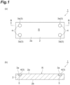
FIG. 1(a) is a plan view of a sample support of an embodiment, andFIG. 1(b) is a sectional view of the sample support taken along line B-B illustrated inFIG. 1(a) . -
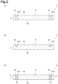
FIGS. 2(a) to 2(c) are sectional views of sample supports of first to third modification examples. -
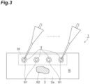
FIG. 3 is a diagram for describing mass calibration using a sample support of a fourth modification example. - Hereinafter, a preferred embodiment of the present disclosure will be described in detail with reference to the drawings. Note that, in each of the drawings, the same reference numerals will be applied to the same or corresponding constituents, and the repeated description will be omitted.
- A
sample support 1 illustrated inFIG. 1 , for example, is used to ionize the components of a sampleto be measured during mass analysis. The sample, for example, is a biological sample or the like. Thesample support 1 includes asubstrate 2. Thesubstrate 2, for example, is formed of an insulating material in a rectangular plate shape, and has afirst surface 2a, and asecond surface 2b on a side opposite to thefirst surface 2a. Thefirst surface 2a and thesecond surface 2b are the main surface of thesubstrate 2, and for example, a flat surface perpendicular to a thickness direction of thesubstrate 2. The length of one side of thesubstrate 2 when viewed in the thickness direction of thesubstrate 2, for example, is approximately several cm, and the thickness of thesubstrate 2, for example, is approximately 1 µm to 1000 µm. - The
substrate 2 has a measurement region R used for the measurement of the sample. In this example, the measurement region R is the entire region of thesubstrate 2. In the measurement region R, a porous structure for communicating thefirst surface 2a and thesecond surface 2b with each other is formed. In this example, the porous structure has a structure in which voids (air gaps) (pores) extend in an irregular direction and are irregularly distributed in three dimensions (an irregular porous structure). The voids in the porous structure configure through holes opened to thefirst surface 2a and thesecond surface 2b. The irregular porous structure, for example, is a sponge-shaped structure. - In this example, the measurement region R (the substrate 2) is formed of a sintered body of glass beads. The sintered body of the glass beads, for example, has a structure in which a plurality of glass beads are integrated by sintering. The shape of each of the glass beads, for example, is a spherical shape. The shapes and the sizes of the glass beads contained in the
substrate 2 may be even, or may be uneven. The porous structure described above is formed of the plurality of glass beads and a plurality of voids formed between the glass beads. The voids between the glass beads are irregularly communicated with each other. The average particle size (diameter) of the glass beads, for example, is approximately 50 µm. In a case where thesubstrate 2 is formed of the sintered body of the glass beads, the porosity of the porous structure, for example, is 40% to 50%. - In the
substrate 2, a plurality of (in this example, four)calibration portions 3 are formed. In this example, each of thecalibration portions 3 is formed by embedding anembedment member 4 in thesubstrate 2. Theembedment member 4, for example, is formed of ceramics in a circular plate shape. That is, theembedment member 4 is formed of a material different from the material of thesubstrate 2. Theembedment member 4 is a solid member in which a hole is not formed. Aconcave portion 5 in a shape corresponding to the embedment member 4 (in a cylindrical shape) is formed in thefirst surface 2a of thesubstrate 2, and theembedment member 4 is tightly embedded in theconcave portion 5. Theembedment member 4, for example, adheres to the bottom surface and the lateral surface of theconcave portion 5 by an adhesive material to be fixed. Theembedment member 4 is disposed in theconcave portion 5 such that the surface of the embedment member on thefirst surface 2a side is flush with thefirst surface 2a. Accordingly, thecalibration portion 3 has asurface 3a flush with thefirst surface 2a. Two surfaces being flush with each other indicates that the two surfaces are positioned on the same surface. - In this example, four
calibration portions 3 are disposed at four corners of thesubstrate 2, respectively. As described above, in this example, the entire region of thesubstrate 2 is the measurement region R used for the measurement of the sample, and each of thecalibration portions 3 is disposed in the measurement region R. - The water absorbability of the
calibration portion 3 is lower thanthe water absorbability of the measurement region R (the substrate 2). That is, in thecalibration portion 3, a liquid is less likely to be absorbed, compared to the measurement region R. In this example, while the measurement region R has the porous structure, theembedment member 4 is formed solid. As a result, the relationship described above is satisfied. That is, the water absorbability of theembedment member 4 is lower than the water absorbability of the measurement region R. In other words, in this embodiment, while the measurement region R is formed as a penetration region including a penetration portion for communicating thefirst surface 2a and thesecond surface 2b with each other, thecalibration portion 3 is formed as a non-penetration region (non-communication region) not including such a penetration portion. As a result, the relationship described above is satisfied. Note that, in a case where thecalibration portion 3 is disposed in the measurement region R, the water absorbability of the measurement region R indicates the water absorbability in a portion of the measurement region R excluding thecalibration portion 3. - The
first surface 2a of thesubstrate 2 and thesurface 3a of thecalibration portion 3 have electrical conductivity. Specifically, a conductive layer is formed on thefirst surface 2a and thesurface 3a. The conductive layer, for example, is continuously (integrally) formed over thefirst surface 2a and thesurface 3a to cover the entirefirst surface 2a except for an opening portion of the porous structure and theentire surface 3a. The conductive layer, for example, is formed of a metal material such as Pt in a thin film shape. The conductive layer is formed thin to the extent that thecalibration portion 3 can be visually observed via the conductive layer. - First, an example of a sample ionization method using the
sample support 1 will be described. As an example, first, a sample placed on slide glass is prepared, and thesample support 1 is disposed on the sample such that thesecond surface 2b of the substrate 2 (the measurement region R) is brought into contact with the sample. Accordingly, the components of the sample are moved toward thefirst surface 2a side from thesecond surface 2b side through a plurality of paths (the voids in the porous structure) formed in thesubstrate 2 by a capillary action. The components of the sample moved to thefirst surface 2a side remain on thefirst surface 2a side by a surface tension. After that, by scanning (irradiating) thefirst surface 2a with laser light in a state where a voltage is applied to the conductive layer on thefirst surface 2a, the components of the sample moved to thefirst surface 2a side are ionized. The ionization method in this example is a laser desorption/ionization method using laser light (an energy line). - The sample ions discharged from the
sample support 1, for example, are detected with an ion detection unit of a mass analysis device. For example, a ground electrode is provided between thesample support 1 and the ion detection unit, and the sample ions are moved toward the ground electrode while being accelerated by a potential difference between the conductive layer and the ground electrode. Then, the sample ions are detected with the ion detection unit, and the mass analysis measurement of the sample is implemented. The ion detection unit detects the sample ions in association with the scanning position of the laser light. The mass analysis device, for example, is a device performing the mass analysis of the sample using time-of-flight mass spectrometry (TOF-MS). - Before such measurement of the sample is started, mass calibration is performed. In the mass calibration, a sample for mass calibration (a calibration sample and a reference sample) is dropped onto the
surface 3a of thecalibration portion 3, and the ionization and the mass analysis measurement described above are implemented on the calibration sample. A mass spectrum is corrected on the basis of a measurement result for the calibration sample. The mass spectrum is a spectrum obtained by the mass analysis, and for example, represented by a graph in which a horizontal axis is set as an m/z value, and a vertical axis is set as a detected strength. The m/z value is a mass-charge ratio obtained by dividing the mass m of the ions by the charge number z. Since the mass spectrum of the calibration sample is known, it is possible to perform the mass calibration of the mass analysis device, on the basis of the measurement result for the calibration sample. The calibration sample has a concentration lower than that of the sample for measurement. In thesample support 1 of the embodiment, since the solvent of the calibration sample on thesurface 3a of thecalibration portion 3 is dried such that the components of the calibration sample are condensed and easily precipitated, it is possible to use the dilute calibration sample. - In the
sample support 1, thecalibration portion 3 including thesurface 3a flush with thefirst surface 2a is formed in thesubstrate 2, and the water absorbability of thecalibration portion 3 is lower than the water absorbability of the measurement region R. Accordingly, in a case where the calibration sample is disposed on thesurface 3a of thecalibration portion 3, the calibration sample is less likely to be absorbed, and the solvent is dried such that the components of the calibration sample are easily precipitated on thesurface 3a. In addition, since thecalibration portion 3 is configured to have the water absorbability different from that of the measurement region R, it is easier to visually grasp the position of thecalibration portion 3. In addition, by thecalibration portion 3 including thesurface 3a flush with thefirst surface 2a of thesubstrate 2, it is possible to accurately perform the mass calibration. Since the time-of-flight shift of the ions strongly depends on a depth direction of an occurrence position, but an influence due to a position in the same plane is small, it is important that thesurface 3a of thecalibration portion 3 is positioned on the same plane as thefirst surface 2a of thesubstrate 2. In addition, since the components of the calibration sample are condensed and easily precipitated, it is possible to use the calibration sample with a low concentration. As described above, according to thesample support 1, it is possible to preferably perform the mass calibration. - The
calibration portion 3 is formed in the measurement region R. Accordingly, it is possible to make thesurface 3a of thecalibration portion 3 reliably flush with thefirst surface 2a. In addition, it is possible to move thecalibration portion 3 close to an area where the actual measurement is performed. - The
calibration portion 3 is formed by embedding theembedment member 4 having the water absorbability lower than the water absorbability of the measurement region R in thesubstrate 2. Accordingly, it is possible to form thecalibration portion 3 with excellent reproducibility, and facilitate the adjustment of the size of thecalibration portion 3. In addition, since it is possible to increase the degree of freedom for selecting the material of thesubstrate 2, it is possible to control the ionization efficiency of the sample. - The plurality of
calibration portions 3 are formed in thesubstrate 2. Accordingly, it is possible to perform the mass calibration by disposing a plurality of calibration samples with concentrations different from each other in the plurality ofcalibration portions 3, respectively, and for example, perform quantitative measurement. The quantitative measurement will be described below with reference toFIG. 3 . - The
calibration portion 3 is formed of the ceramics. Accordingly, it is possible to form thecalibration portion 3 with excellent reproducibility, and facilitate the adjustment of the size of thecalibration portion 3. - The porous structure of the measurement region R is formed of the sintered body of the glass beads. Accordingly, it is possible to preferably configure the porous structure.
- The
first surface 2a and thesurface 3a of thecalibration portion 3 have electrical conductivity. Accordingly, it is possible to ionize the sample by the laser desorption/ionization method as described above. - The
sample support 1 may be configured as with a first modification example illustrated inFIG. 2(a) . In the first modification example, theembedment member 4 is provided to penetrate through thesubstrate 2 along the thickness direction. According to such the first modification example, as with the embodiment described above, it is also possible to preferably perform the mass calibration. - The
sample support 1 may be configured as with a second modification example illustrated inFIG. 2(b) . In the second modification example, thesubstrate 2 and thecalibration portion 3 are formed of porous glass. The porous glass is a sponge-shaped glass plate in which a plurality of pores are irregularly formed and linked. In this example, thecalibration portion 3 is formed by melting and then solidifying a part of the porous structure in the measurement region R. For example, by preparing thesubstrate 2 including a portion to be thecalibration portion 3 after processing, and melting and then solidifying the porous structure in the portion, it is possible to obtain thesubstrate 2. In this case, thecalibration portion 3 is formed in the measurement region R in thesubstrate 2. According to such the second modification example, as with the embodiment described above, it is also possible to preferably perform the mass calibration. In addition, it is possible to facilitate the formation of thecalibration portion 3 and reduce a cost of the formation of the calibration. - The
sample support 1 may be configured as with a third modification example illustrated inFIG. 2(c) . In the third modification example, thesubstrate 2 is formed of porous glass, and thecalibration portion 3 includes afirst portion 31 consisting of porous glass and asecond portion 32 consisting of theembedment member 4. Thefirst portion 31 is configured as with thecalibration portion 3 of the second modification example. Thesecond portion 32 is configured as with thecalibration portion 3 of the embodiment. Thefirst portion 31 is disposed to be exposed to thefirst surface 2a of thesubstrate 2, and thesecond portion 32 is disposed between thefirst portion 31 and thesecond surface 2b of thesubstrate 2. According to such the third modification example, as with the embodiment described above, it is also possible to preferably perform the mass calibration. - As another modification example, the
calibration portion 3 may be formed by filling the porous structure of the measurement region R with a filling material. The filling material, for example, is formed in a powder shape, and filled in the voids of the porous structure. By filling a part of the porous structure with the filling material, it is possible to make the part as thecalibration portion 3 having the water absorbability lower than that of the porous structure. According to such a modification example, as with the embodiment described above, it is also possible to preferably perform the mass calibration. In addition, it is possible to facilitate the formation of thecalibration portion 3 and reduce the cost of the formation of the calibration. - The
sample support 1 may be configured as with a fourth modification example illustrated inFIG. 3 . In the fourth modification example, a plurality of calibration portions 3 (in this example, four calibration portions) are disposed in a row in arectangular region 35. In this example, the plurality ofcalibration portions 3 are arranged at regular intervals along a direction parallel to the long side of thesubstrate 2. According to such a fourth modification example, as with the embodiment described above, it is also possible to preferably perform the mass calibration. In addition, by disposing a plurality of calibration samples S1 with concentrations different from each other in the plurality ofcalibration portions 3 respectively. Therefore, It is possible to perform the mass calibration, and perform the quantitative measurement. For example, first, four calibration samples S1 adjusted so that the concentration changes stepwise are dropped to fourcalibration portions 3 and measured.. Subsequently, the intensity and the concentration of the ions of the measurement target are plotted on the basis of measurement results for four calibration samples S1 to create a calibration curve. Subsequently, a sample S2 to be measured is analyzed and the concentration is estimated on the basis of the calibration curve. Subsequently, for example, in the case of imaging measurement, a concentration map is created. According to the steps described above, it is possible to perform the quantitative measurement. - The present disclosure is not limited to the embodiment and the modification examples described above. The materials and the shapes of each of the configurations are not limited to the materials and the shapes described above, and various materials and shapes can be adopted. For example, the porous structure of the measurement region R may be formed of a fiber porous body. The fiber porous body has a structure (an aggregate) in which a plurality of linear cellulose nanofibers overlap with each other. The fiber porous body, for example, may include a structure in which a plurality of carbon nanofibers, a plurality of fibrous porous silicas, a plurality of glass fibers, or combinations thereof overlap with each other.
- The porous structure of the measurement region R may be formed of anodically oxidized silicon or an anodically oxidized valve metal. In this case, the porous structure has a plurality of through holes formed to communicate the
first surface 2a and thesecond surface 2b of thesubstrate 2 with each other. Such through holes, for example, are a plurality of pores extending along the thickness direction of thesubstrate 2. In this case, the porous structure has a structure in which the plurality of pores are regularly disposed (a regular porous structure). - A case where the porous structure is formed of the anodically oxidized valve metal (for example, aluminum (Al)) will be further described. The porous structure, for example, may be an Al alumina porous film. Specifically, such a porous structure can be obtained by performing an anodization treatment with respect to an Al substrate, and peeling off the oxidized surface portion from the Al substrate. Note that, the porous structure may be formed by anodically oxidizing a valve metal other than Al, such as tantalum (Ta), niobium (Nb), titanium (Ti), hafnium (Hf), zirconium (Zr), zinc (Zn), tungsten (W), bismuth (Bi), and antimony (Sb).
- The porous structure of the measurement region R may be formed of porous ceramic or a porous metal. The structure of the porous ceramic is in a sponge shape in which a plurality of pores are irregularly formed and linked, as with the porous glass. The porous metal is a sponge-shaped metal perforated body (may be referred to as a metal porous body, a foam metal, a porous metal, a perforated metal, or the like) in which a plurality of pores are irregularly formed and linked.
- The conductive layer may not be formed on the
first surface 2a of thesubstrate 2 and thesurface 3a of the calibration portion 3.Thefirst surface 2a and thesurface 3a may have electrical insulating properties. In this case, as with the embodiment described above, it is also possible to preferably perform the mass calibration. For example, the sample can be ionized by a desorption electrospray ionization method in which the sample is desorbed and ionized by irradiating the sample with electrically charged minute liquid droplets. - In the embodiment described above, the entire region of the
substrate 2 is the measurement region R, but only a part of thesubstrate 2 may configure the measurement region R. In this case, a portion of thesubstrate 2 except for the measurement region R may not include the porous structure. Thecalibration portion 3 may be formed in the portion of thesubstrate 2 except for the measurement region R. The shape of thecalibration portion 3 is not limited to a circular shape, and may be any shape such as a square shape, a rectangular shape, and an elliptical shape. Thesurface 3a of thecalibration portion 3 may be subjected to a hydrophilic treatment to have hydrophilicity higher than that of thefirst surface 2a of thesubstrate 2. In this case, it is possible to suppress the infiltration of the calibration sample dropped onto thesurface 3a into thefirst surface 2a. A groove may be formed in the boundary portion between thesurface 3a and thefirst surface 2a by half-etching. In this case, thesurface 3a is easily distinguished from thefirst surface 2a to be visually recognized. In addition, it is possible to suppress the infiltration of the calibration sample dropped onto thesurface 3a into thefirst surface 2a. - In the embodiment described above, the
embedment member 4 may be formed of a material other than the ceramics, for example, a metal material or an organic material. It may not be necessary to form the plurality ofcalibration portions 3, and only onecalibration portion 3 may be formed. In the example of the method for using thesample support 1 described above, the sample is supplied from thesecond surface 2b side of thesubstrate 2, but the sample may be supplied from thefirst surface 2a side. For example, the sample may be supplied onto thefirst surface 2a by placing the sample on thefirst surface 2a such that the components of the sample are infiltrated into thesubstrate 2, and then, removing the sample. - 1: sample support, 2: substrate, 2a: first surface, 2b: second surface, 3: calibration portion, 3a: surface, R: measurement region.
Claims (12)
- A sample support used for ionization of a sample, the support comprising:a substrate including a first surface, and a second surface on a side opposite to the first surface, and including a measurement region in which a porous structure for communicating the first surface and the second surface with each other is formed;wherein a calibration portion including a surface flush with the first surface is formed in the substrate; andwater absorbability of the calibration portion is lower than the water absorbability of the measurement region.
- The sample support according to claim 1,
wherein the calibration portion is formed in the measurement region. - The sample support according to claim 1 or 2,
wherein the calibration portion is formed of a material different from a material of the substrate. - The sample support according to claim 1 or 2,
wherein the calibration portion is formed of a same material as a material of the substrate. - The sample support according to any one of claims 1 to 4,
wherein the calibration portion is formed by embedding a member having water absorbability lower than the water absorbability of the measurement region in the substrate. - The sample support according to any one of claims 1, 2, and 4,wherein the porous structure is formed of a material including glass; andthe calibration portion is formed by melting and then solidifying a part of the porous structure.
- The sample support according to any one of claims 1 to 4,
wherein the calibration portion is formed by filling the porous structure with a filling material. - The sample support according to any one of claims 1 to 7,
wherein a plurality of the calibration portions are formed in the substrate. - The sample support according to any one of claims 1 to 8,
wherein the calibration portion is formed of ceramics. - The sample support according to any one of claims 1 to 8,
wherein the porous structure is formed of a sintered body of glass beads, porous glass, a fiber porous body, anodically oxidized silicon, an anodically oxidized valve metal, porous ceramic, or a porous metal. - The sample support according to any one of claims 1 to 10,
wherein the first surface and the surface of the calibration portion have electrical conductivity. - The sample support according to any one of claims 1 to 10,
wherein the first surface and the surface of the calibration portion have electrical insulating properties.
Applications Claiming Priority (2)
| Application Number | Priority Date | Filing Date | Title |
|---|---|---|---|
| JP2021208136A JP7206365B1 (en) | 2021-12-22 | 2021-12-22 | sample support |
| PCT/JP2022/033317 WO2023119741A1 (en) | 2021-12-22 | 2022-09-05 | Sample support |
Publications (2)
| Publication Number | Publication Date |
|---|---|
| EP4382903A1 true EP4382903A1 (en) | 2024-06-12 |
| EP4382903A4 EP4382903A4 (en) | 2025-07-23 |
Family
ID=84923485
Family Applications (1)
| Application Number | Title | Priority Date | Filing Date |
|---|---|---|---|
| EP22910468.2A Pending EP4382903A4 (en) | 2021-12-22 | 2022-09-05 | SAMPLE CARRIER |
Country Status (5)
| Country | Link |
|---|---|
| US (1) | US20250014881A1 (en) |
| EP (1) | EP4382903A4 (en) |
| JP (1) | JP7206365B1 (en) |
| CN (1) | CN118451319A (en) |
| WO (1) | WO2023119741A1 (en) |
Families Citing this family (1)
| Publication number | Priority date | Publication date | Assignee | Title |
|---|---|---|---|---|
| JP7506802B1 (en) * | 2023-06-07 | 2024-06-26 | 浜松ホトニクス株式会社 | Sample Support |
Family Cites Families (9)
| Publication number | Priority date | Publication date | Assignee | Title |
|---|---|---|---|---|
| US6627444B1 (en) * | 2000-08-07 | 2003-09-30 | Smiths Detection - Toronto Ltd. | Method and solid phase calibration sample for calibration of analytical instructions |
| CA2608965C (en) * | 2005-06-30 | 2014-08-19 | Biocrates Life Sciences Ag | Device for quantitative analysis of a metabolite profile |
| US7825375B2 (en) * | 2005-11-14 | 2010-11-02 | Nec Corporation | Microchip, method for using such microchip and mass spectrometry system |
| JP5756611B2 (en) * | 2010-10-07 | 2015-07-29 | 株式会社 資生堂 | Analysis method |
| JP5970246B2 (en) * | 2011-06-07 | 2016-08-17 | 株式会社 資生堂 | Analysis method and analysis kit |
| US11047827B2 (en) * | 2017-09-21 | 2021-06-29 | Hamamatsu Photonics K.K. | Sample support body |
| WO2019155741A1 (en) | 2018-02-09 | 2019-08-15 | 浜松ホトニクス株式会社 | Sample support |
| JP7199054B2 (en) * | 2018-11-07 | 2023-01-05 | 国立大学法人東海国立大学機構 | Mass spectrometric method for elements in a sample, analytical device used for said mass spectrometric method, and sample capture kit |
| JP7333280B2 (en) * | 2020-02-04 | 2023-08-24 | 浜松ホトニクス株式会社 | SAMPLE SUPPORT AND METHOD FOR MANUFACTURING SAMPLE SUPPORT |
-
2021
- 2021-12-22 JP JP2021208136A patent/JP7206365B1/en active Active
-
2022
- 2022-09-05 US US18/709,584 patent/US20250014881A1/en active Pending
- 2022-09-05 CN CN202280084162.0A patent/CN118451319A/en active Pending
- 2022-09-05 EP EP22910468.2A patent/EP4382903A4/en active Pending
- 2022-09-05 WO PCT/JP2022/033317 patent/WO2023119741A1/en not_active Ceased
Also Published As
| Publication number | Publication date |
|---|---|
| JP2023092871A (en) | 2023-07-04 |
| CN118451319A (en) | 2024-08-06 |
| WO2023119741A1 (en) | 2023-06-29 |
| JP7206365B1 (en) | 2023-01-17 |
| EP4382903A4 (en) | 2025-07-23 |
| US20250014881A1 (en) | 2025-01-09 |
Similar Documents
| Publication | Publication Date | Title |
|---|---|---|
| CN107076705B (en) | Surface-assisted laser desorption ionization method, mass analysis method and mass analysis device | |
| CN106796198B (en) | Sample support and manufacturing method of sample support | |
| US11164733B2 (en) | Fabrication of mass spectrometry surface | |
| EP0793097A2 (en) | Apparatus for collecting analyte samples from capillary electrophoresis | |
| US20090069177A1 (en) | Laser desorption substrate | |
| CN111512151B (en) | Ionization method and sample support | |
| CN111699384B (en) | Sample support | |
| JPWO2019058857A1 (en) | Sample support | |
| US20250014881A1 (en) | Sample support | |
| CN110383056A (en) | Mass analysis device and mass analysis method | |
| JP5278625B2 (en) | Sensor chip and storage method thereof | |
| CN111512150B (en) | Sample support, method for producing sample support, and method for ionizing sample | |
| EP3152582B1 (en) | Methods of detecting biological prints, fluids or analytes therein using porous semiconductor substrates | |
| US12205811B2 (en) | Sample supports for solid-substrate electrospray mass spectrometry | |
| JP2006514738A (en) | Method for producing sample carrier for MALDI mass spectrometry | |
| JP2011013013A (en) | Biological tissue extract holding substrate | |
| CN118475825A (en) | Sample support unit and method for ionizing sample | |
| JP7236295B2 (en) | Sample support, ionization method, and mass spectrometry method | |
| EP4137448A1 (en) | Sample support | |
| JP7233268B2 (en) | Sample support, ionization method, and mass spectrometry method | |
| KR20190060357A (en) | Substrate for Laser Desorption Ionization Mass Spectrometry and Mass analysis method using the same | |
| WO2019155834A1 (en) | Sample support, ionization method, and mass spectrometry method | |
| Class et al. | Patent application title: METHODS OF DETECTING BIOLOGICAL PRINTS, FLUIDS OR ANALYTES THEREIN USING POROUS SEMICONDUCTOR SUBSTRATES |
Legal Events
| Date | Code | Title | Description |
|---|---|---|---|
| STAA | Information on the status of an ep patent application or granted ep patent |
Free format text: STATUS: THE INTERNATIONAL PUBLICATION HAS BEEN MADE |
|
| PUAI | Public reference made under article 153(3) epc to a published international application that has entered the european phase |
Free format text: ORIGINAL CODE: 0009012 |
|
| STAA | Information on the status of an ep patent application or granted ep patent |
Free format text: STATUS: REQUEST FOR EXAMINATION WAS MADE |
|
| 17P | Request for examination filed |
Effective date: 20240306 |
|
| AK | Designated contracting states |
Kind code of ref document: A1 Designated state(s): AL AT BE BG CH CY CZ DE DK EE ES FI FR GB GR HR HU IE IS IT LI LT LU LV MC MK MT NL NO PL PT RO RS SE SI SK SM TR |
|
| DAV | Request for validation of the european patent (deleted) | ||
| DAX | Request for extension of the european patent (deleted) | ||
| A4 | Supplementary search report drawn up and despatched |
Effective date: 20250623 |
|
| RIC1 | Information provided on ipc code assigned before grant |
Ipc: G01N 27/62 20210101AFI20250616BHEP Ipc: H01J 49/00 20060101ALI20250616BHEP Ipc: H01J 49/04 20060101ALI20250616BHEP Ipc: H01J 49/16 20060101ALI20250616BHEP |
|
| STAA | Information on the status of an ep patent application or granted ep patent |
Free format text: STATUS: THE APPLICATION IS DEEMED TO BE WITHDRAWN |