EP4382877A1 - Automated identification of vehicle variants for maintenance operations - Google Patents
Automated identification of vehicle variants for maintenance operations Download PDFInfo
- Publication number
- EP4382877A1 EP4382877A1 EP22211780.6A EP22211780A EP4382877A1 EP 4382877 A1 EP4382877 A1 EP 4382877A1 EP 22211780 A EP22211780 A EP 22211780A EP 4382877 A1 EP4382877 A1 EP 4382877A1
- Authority
- EP
- European Patent Office
- Prior art keywords
- vehicle
- location
- sensor device
- potential leak
- respect
- Prior art date
- Legal status (The legal status is an assumption and is not a legal conclusion. Google has not performed a legal analysis and makes no representation as to the accuracy of the status listed.)
- Pending
Links
Images




Classifications
-
- G—PHYSICS
- G07—CHECKING-DEVICES
- G07C—TIME OR ATTENDANCE REGISTERS; REGISTERING OR INDICATING THE WORKING OF MACHINES; GENERATING RANDOM NUMBERS; VOTING OR LOTTERY APPARATUS; ARRANGEMENTS, SYSTEMS OR APPARATUS FOR CHECKING NOT PROVIDED FOR ELSEWHERE
- G07C5/00—Registering or indicating the working of vehicles
- G07C5/08—Registering or indicating performance data other than driving, working, idle, or waiting time, with or without registering driving, working, idle or waiting time
- G07C5/0808—Diagnosing performance data
-
- G—PHYSICS
- G01—MEASURING; TESTING
- G01L—MEASURING FORCE, STRESS, TORQUE, WORK, MECHANICAL POWER, MECHANICAL EFFICIENCY, OR FLUID PRESSURE
- G01L17/00—Devices or apparatus for measuring tyre pressure or the pressure in other inflated bodies
-
- G—PHYSICS
- G01—MEASURING; TESTING
- G01M—TESTING STATIC OR DYNAMIC BALANCE OF MACHINES OR STRUCTURES; TESTING OF STRUCTURES OR APPARATUS, NOT OTHERWISE PROVIDED FOR
- G01M17/00—Testing of vehicles
- G01M17/007—Wheeled or endless-tracked vehicles
- G01M17/02—Tyres
-
- G—PHYSICS
- G01—MEASURING; TESTING
- G01M—TESTING STATIC OR DYNAMIC BALANCE OF MACHINES OR STRUCTURES; TESTING OF STRUCTURES OR APPARATUS, NOT OTHERWISE PROVIDED FOR
- G01M3/00—Investigating fluid-tightness of structures
- G01M3/02—Investigating fluid-tightness of structures by using fluid or vacuum
- G01M3/04—Investigating fluid-tightness of structures by using fluid or vacuum by detecting the presence of fluid at the leakage point
- G01M3/24—Investigating fluid-tightness of structures by using fluid or vacuum by detecting the presence of fluid at the leakage point using infrasonic, sonic or ultrasonic vibrations
-
- G—PHYSICS
- G06—COMPUTING OR CALCULATING; COUNTING
- G06K—GRAPHICAL DATA READING; PRESENTATION OF DATA; RECORD CARRIERS; HANDLING RECORD CARRIERS
- G06K7/00—Methods or arrangements for sensing record carriers, e.g. for reading patterns
- G06K7/10—Methods or arrangements for sensing record carriers, e.g. for reading patterns by electromagnetic radiation, e.g. optical sensing; by corpuscular radiation
- G06K7/10009—Methods or arrangements for sensing record carriers, e.g. for reading patterns by electromagnetic radiation, e.g. optical sensing; by corpuscular radiation sensing by radiation using wavelengths larger than 0.1 mm, e.g. radio-waves or microwaves
- G06K7/10366—Methods or arrangements for sensing record carriers, e.g. for reading patterns by electromagnetic radiation, e.g. optical sensing; by corpuscular radiation sensing by radiation using wavelengths larger than 0.1 mm, e.g. radio-waves or microwaves the interrogation device being adapted for miscellaneous applications
Definitions
- the disclosure relates generally to vehicle maintenance operations.
- the disclosure relates to automated identification of vehicle variants for maintenance operations.
- the disclosure can be applied in heavy-duty vehicles, such as trucks, buses, and construction equipment.
- trucks, buses, and construction equipment such as trucks, buses, and construction equipment.
- Maintenance and repair of vehicles may be performed manually and/or using automated processes.
- One challenge with automation is instructing a robot or other device to perform operations at a correct location on a vehicle. This problem is further complicated by the proliferation of different models and configurations of vehicles, which may have unique arrangements of different components and systems.
- a computer-implemented method may include receiving, by a processor device of a computer system, vehicle identifier data indicative of a vehicle.
- the method may further include obtaining, by the processor device, a vehicle configuration of the vehicle based on the vehicle identifier data, the vehicle configuration including at least one potential leak location.
- the method may further include moving, by the processor device, a first sensor device to the at least one potential leak location with respect to the vehicle.
- the method may further include receiving, by the processor device, a measurement from the first sensor device.
- a technical benefit may include automating a leak detection process.
- receiving the vehicle identifier data may further include receiving an image from a camera, the image including a vehicle identifier comprising a text string.
- Obtaining the vehicle configuration may further include identifying the text string based on the image, and retrieving the vehicle configuration from a vehicle configuration database of predetermined vehicle configurations based on the identified text string.
- the first sensor device may include an ultrasonic sensor device.
- the measurement from the first sensor device may include an ultrasonic sensor measurement indicative of an air leak.
- the method may further include receiving, by the processor device, a measurement from a second sensor device indicative of a location of the vehicle relative to a predetermined ground location, wherein moving the first sensor device at the at least one potential leak location with respect to the vehicle is based in part on the measurement from the second sensor device.
- the second sensor device may include a pressure sensor device.
- a technical benefit may include automating a leak detection process.
- receiving the vehicle identifier data may further include receiving an image from a camera, the image including the vehicle identifier.
- a technical benefit may include identifying a vehicle using pre-existing vehicle markings.
- the at least one potential leak location may be at least one location in a pneumatic system of the vehicle.
- a technical benefit may include detecting an air leak in a pneumatic system.
- the at least one potential leak location may be at least one location in a hydraulic system of the vehicle.
- a technical benefit may include detecting a fluid leak in a hydraulic system.
- the at least one potential leak location may include a plurality of potential leak locations with respect to the vehicle.
- a technical benefit may include inspecting several locations of a system during a single inspection process.
- the method may further include receiving, by the processor device, a measurement from a second sensor device indicative of a location of the vehicle relative to a predetermined ground location, wherein the command to automatically position the first sensor device at the at least one potential leak location with respect to the vehicle is based in part on the measurement from the second sensor device.
- a technical benefit may include more accurately determining the relative positions of vehicle components.
- the method may further include determining, by the processor device, the location of the vehicle relative to the predetermined ground location based on the measurement from the second sensor device.
- the method may further include determining, by the processor device, the at least one potential leak location with respect to the predetermined ground location based on the vehicle configuration and the location of the vehicle relative to the predetermined ground location. Moving the first sensor device to the at least one potential leak location with respect to the vehicle may be based on the at least one potential leak location with respect to the predetermined ground location.
- a technical benefit may include more accurately determining the relative positions of vehicle components.
- the vehicle identifier data may include Radio-Frequency Identification data received from an RFID tag on the vehicle, and identifying the vehicle configuration may be based on the RFID data.
- a technical benefit may include more accurately determining the relative positions of vehicle components.
- a technical benefit may include identifying a vehicle using wireless components.
- the first sensor device may include an ultrasonic sensor device.
- a technical benefit may include accurately detecting leaks using ultrasonic waves.
- moving the first sensor device to the at least one potential leak location with respect to the vehicle may include operating a robot arm comprising the first sensor device to move the first sensor device to the at least one potential leak location.
- a technical benefit may include automating a leak detection process.
- the command to operate the robot arm to position the first sensor device at the at least one potential leak location may be further based on a relative location of a wheel of the vehicle relative to a base portion of the robot arm, and a relative location of the at least one potential leak location with respect to the relative location of the wheel of the vehicle.
- a technical benefit may include more accurately determining relative locations of vehicle components.
- a computer system may be configured to perform the method.
- a technical benefit may include automating a leak detection process.
- a non-transitory computer-readable storage medium may include instructions, which when executed by a processor device, cause the processor device to perform the method.
- a technical benefit may include automating a leak detection process.
- a computer program product may include program code for performing, when executed by a processor device, the method.
- a technical benefit may include automating a leak detection process.
- the method may further include receiving, by the processor device of a computer system, vehicle identifier data indicative of a second vehicle.
- the method may further include obtaining, by the processor device, a vehicle configuration of the vehicle based on the vehicle identifier data, the vehicle configuration including at least one second potential leak location.
- the method may further include moving, by the processor device, the first sensor device to the at least one second potential leak location with respect to the vehicle.
- the method may further include receiving, by the processor device, a second measurement from the first sensor device.
- a technical benefit may include automating a leak detection process for multiple vehicles.
- the vehicle may include a commercial truck.
- a technical benefit may include automating a leak detection process for a commercial truck.
- the method may further include sending, by the processor device, a second command to automatically position the first sensor device at a second potential leak location with respect to the vehicle.
- the method may further include receiving, by the processor device, a second measurement from the first sensor device.
- a technical benefit may include automating a leak detection process for multiple locations on a vehicle.
- the second sensor device may include a pressure sensor device.
- a technical benefit may include more accurately determining relative locations of vehicle components.
- receiving the vehicle identifier data may further include receiving an image from a camera, the image including a vehicle identifier comprising a text string.
- Obtaining the vehicle configuration may further include identifying the text string based on the image, and retrieving the vehicle configuration from a vehicle configuration database of predetermined vehicle configurations based on the identified text string.
- a technical benefit may include identifying a vehicle using pre-existing vehicle markings.
- control units computer readable media
- computer program products associated with the above discussed technical benepfits.
- the disclosure relates generally to vehicle maintenance operations.
- the disclosure relates to automated identification of vehicle variants for maintenance operations.
- a vehicle configuration for a vehicle including potential leak locations for the vehicle, are obtained from vehicle identifier data.
- a sensor device is moved to the potential leak locations and measurements from the sensor device are received.
- moving the sensor device to the potential leak locations can be automated for different vehicles and vehicle configurations using robotic inspection system.
- FIGS. 1A and 1B are exemplary views of inspections of different types of vehicles 100A, 100B using a movable robot arm 110, according to one example.
- a truck 100A has a chassis 102A, a cab 104A coupled to the chassis 102A, and a plurality of wheels 106A in a first configuration (e.g., two axles, with two wheels on the front axle and two or four wheels on the rear axle).
- each configuration may include defined aspects of the vehicle, such as vehicle length, vehicle width, number of axles, wheelbase, front and rear overhang, etc.
- a robot arm 110 may move along a rail system 114 and positions a sensor device 112 at predetermined locations on the vehicle 100A to take measurements of various systems and/or components.
- the robot 110 may position the sensor device 112 at one or more potential leak locations, such as components of a pneumatic and/or hydraulic system of the vehicle 100A that are known to be likely failure points, to diagnose fluid leaks.
- potential leak locations such as components of a pneumatic and/or hydraulic system of the vehicle 100A that are known to be likely failure points, to diagnose fluid leaks.
- other movement systems for the robot arm 110, or a similar robot may be used.
- another truck 100B has a chassis 102B, a cab 104B coupled to the chassis 102B, and a different plurality of wheels 106B in a second configuration (e.g., four axles, with two wheels on the front axle and two or four wheels on each rear axle).
- the robot arm 110 moves along the rail system 114 and positions the sensor device 112 at different predetermined locations on the vehicle 110B to take measurements.
- the configuration of the vehicle 100B may have different potential leak locations, such that the robot arm 110 is positioned and operated differently when inspecting the vehicle 110B of FIG. 1B .
- FIG. 2 is an exemplary view of the robot arm 110 of FIGS. 1A and 1B , according to one example.
- the exemplary robot arm 110 is movably attached to the rail system 114 via a movable base 111.
- the first sensor device 112 is an ultrasonic sensor device 134 that is capable of detecting an air leak when the ultrasonic sensor device 134 is positioned in proximity to the air leak.
- the first sensor device 112 may include a video camera, thermal camera, and/or other appropriate sensor devices, as desired.
- the robot arm 110 in this example may be manipulable about a number of axes 113 (six axes 113 in this example) to position the first sensor device 112 with up to six degrees of freedom so that the first sensor device 112 may be positioned in an optimal position and orientation to detect a leak at each potential leak location.
- the robot arm 110 may include a robot controller 115 for controlling the robot arm 110 and/or for communicating with an external computing system. It should be understood, however, that any number of different arrangements may be used to implement aspects of the disclosure, as desired.
- FIG. 3 is an exemplary view of an inspection bay 322 for a vehicle 100A, the vehicle 100B of FIG. 1B , and/or other vehicles.
- the inspection bay 322 includes a sunken work area 309 that includes a rail system 314 and movable robot arm 310 similar to the robot arm 110 of FIGS. 1A-2 .
- the inspection bay 322 in this example includes one or more sensor devices 316 to determine a relative location of the vehicle 100A and components thereof in relation to a predetermined ground location 318.
- the sensor device(s) 316 may be part of a wheel tracking system 317 that may be used to determine a relative location of the wheels 106A with respect to the predetermined ground location 318.
- the wheel tracking system 317 may use one or more laser sensors or other sensors to obtain a precise location for the wheels 106A, which in turn allows for determining the precise locations for each of the potential leak locations.
- the sensor device(s) 316 may include a pressure sensor device 320 that detects the presence of the wheels 106A of the vehicle 100A at the predetermined ground location 318.
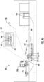
- FIGS. FIGS. 4A and 4B are views of an identification and inspection process for the vehicle 100A in the inspection bay 322, according to one example.
- the inspection bay 322 further includes a computer system 438 and one or more cameras 426 to identify the vehicle 100A and the configuration 458 thereof.
- the camera 426 captures an image 428 of a portion of the vehicle 100A that includes a vehicle identifier 430 for the vehicle 100A.
- the vehicle identifier 430 is a text string 432 of an identification tag 431, such as a license plate for example.
- the camera 426 may also replace or be combined with the sensor(s) 316 for determining the relative location of the wheels 106A with respect to the predetermined ground location 318.
- the image 428 captured by the camera 426 may also be used to determine the relative location of the wheels 106A, thereby reducing the total number of components employed for the inspection process.
- the vehicle identifier can also or alternatively include Radio-Frequency Identification RFID data received from an RFID tag 433 on the vehicle 100A, wherein identifying the vehicle configuration 458 is based at least in part on the RFID data.
- the computer system 438 next receives vehicle identifier data 452 indicative of the vehicle identifier 430 of the vehicle 100A.
- receiving the vehicle identifier data 452 includes receiving the captured image 428 from the camera 426.
- the vehicle identifier data 452 may be stored in a vehicle identification database 450 of predetermined vehicle configurations that is accessible by the computer system 438.
- the vehicle identification database stored on the computer system 438 and/or another local or remote computer system, e.g., on a server, as desired.
- the vehicle identification database 450 may receive and store vehicle identifier data 452 for identifying different types of vehicles and/or different individual vehicles having known configurations.
- the vehicle identification database 450 may also include a vehicle configuration database 454 having a plurality of vehicle configurations 456. Each vehicle configuration 456 may include information specific to the vehicle configuration 456, such as potential leak locations 458 and wheel locations 460 for example.
- the computer system 438 obtains a vehicle configuration of the vehicle 100A based on the vehicle identifier data, e.g., by identifying the text string 432 based on the vehicle identifier data 452, and retrieves the vehicle configuration 456 for the vehicle 100A from the vehicle identification database 450 .
- Identification of the text string 432 or other vehicle identifier 454 may be performed by the computer system 438 or other system using a machine-learning model or other process for extracting alphanumeric values from captured image 428.
- a vehicle configuration 456 is retrieved for the vehicle 100A, including potential leak location data 458, wheel locations 460, and/or other information, as desired.
- Locations of the potential leak locations 408 may be determined using the potential leak location data 458 relative to a sensor, e.g., sensor 312, so that the sensor can be moved to the potential leak locations 458 to obtain appropriate measurements.
- a measurement from the sensor device 316, i.e., the pressure sensor device 320 is received by the computer system 438, with the measurement indicative of a location of the vehicle 100A relative to the predetermined ground location 318.
- the computer system 438 may determine the location of the vehicle 100A relative to the predetermined ground location 318 based on the measurement from the second sensor device 316, and may determine potential leak locations 408 with respect to the predetermined ground location 318 based on the determined vehicle configuration and the location of the vehicle 100A relative to the predetermined ground location 318.
- the relative locations of the potential leak locations 408 can be determined using the potential leak location data 458 and the wheel location data 460 of the vehicle configuration 456, in relation to each other and in relation to the location of the robot arm 310.
- the computer system 438 may determine a number of specifications from the determined locations of the wheels 106A and/or other components, such as a number of wheels 106A, a number of axles, a wheelbase of the vehicle 100A, front and rear overhang, etc., and may match the determined specifications to the appropriate vehicle configuration 456 in the vehicle configuration database 454.
- the computer system 438 may include a user interface 464 for displaying information to and interacting with an operator.
- the user interface 464 may display a graphical representation 466 of the vehicle 106 within the inspection bay 322 including relevant systems, e.g., pneumatic system 407, and the potential leak locations 408 for the vehicle 100A, as well as other components, e.g., wheels 106A, and relative positions of the robot arm 310 with respect to the vehicle 100A and potential leak locations 408.
- the operator may manually select the vehicle configuration 456, e.g., from a list of potential vehicle configurations 456 having similar specifications.
- the computer system 438 can then access a robot program 462 corresponding to the determined vehicle configuration 456 containing instructions to move the robot arm 310 to position the first sensor device 312 at a first leak location 424 of the potential leak locations 408, and take appropriate measurements, e.g., ultrasonic sensor measurements indicative of an air leak in a pneumatic system 407 and/or a fluid leak in a hydraulic system 411, for example.
- the robot programs 462 for the different vehicle configurations 456 may be stored and accessed from the vehicle identification database 450, and/or separately stored and accessed from another location, such as the robot controller (e.g., robot controller 115 of FIG. 2 ), as desired.
- the robot arm 310 is then moved to position the first sensor device 312 at a second leak location 425 of the potential leak locations 408, and take appropriate measurements, and so on.
- Identifying the vehicle configuration 456 from a vehicle configuration database 454 may be beneficial over conventional identification methods, such as manual identification, for a number of reasons. For example, accurately identifying a vehicle configuration 456 allows the correct robot program 462 for the vehicle 100A, that accounts for variations in placement of components in different vehicle configurations 456, to be reliably and automatically selected.
- the robot program 462 may direct the robot arm 310 to move and orient the first sensor device 312 to take measurements at one or more specific targets, e.g., the potential leak locations 408.
- the robot arm 310 By directing the robot arm 310 to specific potential leak locations 408 with specific positions and orientations for the first sensor device 312, the presence and locations of actual leaks may be more accurately detected and measured, as opposed to a broader scan of the vehicle 100A using a sensor covering a wider area, which may fail to detect or accurately measure potential leaks.
- the measurements are received by the computer system 438, and can be used for subsequent operations, such as logging detected air leaks for further inspection, alerting a technician to the presence of an air leak, and/or any other appropriate operation, as desired.
- the user interface 464 highlights actual leak locations 470 in the graphical representation 466 of the vehicle 100A, highlighting potential leak locations 408 where the measurements from the first sensor device 312 are indicative of a leak.
- the user interface 464 may display additional information, as desired, such as videos or images captured during the inspection, a table or list of measurements for the potential leak locations 408, and/or may permit the operator to input comments or additional information, e.g., a repair suggestion, to aid in post-inspection maintenance and/or repair.
- the measurements can also be stored on the computer system 438 or elsewhere, which may allow measurements of numerous vehicles over time to be accurately collected and cataloged for use in data-driven decision-making for subsequent inspections, e.g., determining when maintenance and/or repair is required, rather than subjective decision-making during inspection.
- FIG. 5 is a view of an identification and inspection process for the vehicle 100B of FIG. 1B in the inspection bay 322 of FIGS. 4A and 4B , according to one example.
- the camera 426 captures an image 528 of a portion of the vehicle 100B that includes a different vehicle identifier 530 for the vehicle 100B, e.g., a text string 532 of an identification tag 531.
- the computer system 438 receives the image 528 and obtains vehicle identifier data that includes a vehicle configuration for the vehicle 100B with locations of a plurality of different potential leak locations 508 for the vehicle 100B.
- the computer system 438 may determine relative locations of the potential leak locations 508 based on determining a location of the wheels 106B of the vehicle 100B with respect to the predetermined ground location 318.
- the computer system 438 may move the robot arm 310 to each potential leak location 508 and take appropriate measurements using similar features and operations described above with respect to FIGS. 4A and 4B .
- FIG. 6 is an exemplary block diagram of an exemplary computer system 600 in communication with the vehicle identification database 450 (which may be locally or remotely stored in this example) for performing identification and inspection of a vehicle, according to one example.
- the computer system 600, vehicle identification database, and/or features therein may be incorporated into the computer system 348 of FIGS. 3-5 , and/or may be in communication therewith.
- the computer system 600 may include a processor circuit 602 and a memory 610 in communication with the vehicle identification database 450.
- the vehicle identification database 450 may include vehicle identifier data 452 for identifying different types of vehicles and/or different individual vehicles having known configurations.
- the vehicle identification database 450 may also include a vehicle configuration database 454 having a plurality of vehicle configurations 456. Each vehicle configuration 456 may include information specific to the vehicle configuration 456, such as potential leak location data 458 and wheel location data 460 for example.
- the computer system 600 may access the vehicle identification database 450 to obtain vehicle identifier data 452 to identify a particular vehicle, e.g., vehicle 100A. Based on the vehicle identifier data 452, a vehicle configuration 456 including potential leak location data 458 and wheel location data 460 is retrieved. Using the vehicle configuration 456, locations of the potential leak locations, e.g., leak locations 408, relative to a sensor, e.g., sensor 312, are determined, and a robot program 462 associated with the vehicle configuration 456 may be used to direct a robot to move the sensor to the potential leak locations 408 and obtain appropriate measurements.
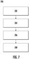
- FIG. 7 is a flow chart of an exemplary method 700 to identify and inspect a vehicle, according to one example.
- the method 700 may include receiving, by a processor device (such as the processor device 602 of FIG. 6 ) of a computer system (such as computer system 438 of FIG. 4B and/or computer system 600), vehicle identifier data (such as vehicle identifier data 652) indicative of a vehicle 100A, 100B (Block 702).
- a processor device such as the processor device 602 of FIG. 6
- a computer system such as computer system 438 of FIG. 4B and/or computer system 600
- vehicle identifier data such as vehicle identifier data 652
- the method 700 may further include obtaining, by the processor device 602, a vehicle configuration (such as vehicle configuration 654) of the vehicle 100A based on the vehicle identifier data 652, the vehicle configuration 654 including at least one potential leak location (such as potential leak location data 458 indicative of locations 408, 508 (Block 702).
- a vehicle configuration such as vehicle configuration 654 of the vehicle 100A based on the vehicle identifier data 652, the vehicle configuration 654 including at least one potential leak location (such as potential leak location data 458 indicative of locations 408, 508 (Block 702).
- the method 700 may further include moving, by the processor device 602, a first sensor device 312 to the at least one potential leak location 408, 508 with respect to the vehicle 100A, 100B (Block 706).
- the method 700 may further include receiving, by the processor device 602, a measurement from the first sensor device 312 (Block 708).
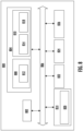
- FIG. 8 is a schematic diagram of a computer system 800 having additional components for implementing examples disclosed herein.
- the computer systems 438, 700, and 800, and/or components thereof may be used interchangeably in some examples, as desired.
- the computer system 800 is adapted to execute instructions from a computer-readable medium to perform these and/or any of the functions or processing described herein.
- the computer system 800 may be connected (e.g., networked) to other machines in a LAN, an intranet, an extranet, or the Internet. While only a single device is illustrated, the computer system 800 may include any collection of devices that individually or jointly execute a set (or multiple sets) of instructions to perform any one or more of the methodologies discussed herein.
- any reference in the disclosure and/or claims to a computer system, computing system, computer device, computing device, control system, control unit, electronic control unit (ECU), processor device, etc. includes reference to one or more such devices to individually or jointly execute a set (or multiple sets) of instructions to perform any one or more of the methodologies discussed herein.
- control system may include a single control unit or a plurality of control units connected or otherwise communicatively coupled to each other, such that any performed function may be distributed between the control units as desired.
- such devices may communicate with each other or other devices by various system architectures, such as directly or via a Controller Area Network (CAN) bus, etc.
- CAN Controller Area Network
- the computer system 800 may comprise at least one computing device or electronic device capable of including firmware, hardware, and/or executing software instructions to implement the functionality described herein.
- the computer system 800 may include a processor device 802 (may also be referred to as a control unit), a memory 804, and a system bus 806.
- the computer system 800 may include at least one computing device having the processor device 802.
- the system bus 806 provides an interface for system components including, but not limited to, the memory 804 and the processor device 802.
- the processor device 802 may include any number of hardware components for conducting data or signal processing or for executing computer code stored in memory 804.
- the processor device 802 may, for example, include a general-purpose processor, an application specific processor, a Digital Signal Processor (DSP), an Application Specific Integrated Circuit (ASIC), a Field Programmable Gate Array (FPGA), a circuit containing processing components, a group of distributed processing components, a group of distributed computers configured for processing, or other programmable logic device, discrete gate or transistor logic, discrete hardware components, or any combination thereof designed to perform the functions described herein.
- the processor device may further include computer executable code that controls operation of the programmable device.
- the system bus 806 may be any of several types of bus structures that may further interconnect to a memory bus (with or without a memory controller), a peripheral bus, and/or a local bus using any of a variety of bus architectures.
- the memory 804 may be one or more devices for storing data and/or computer code for completing or facilitating methods described herein.
- the memory 804 may include database components, object code components, script components, or other types of information structure for supporting the various activities herein. Any distributed or local memory device may be utilized with the systems and methods of this description.
- the memory 804 may be communicably connected to the processor device 802 (e.g., via a circuit or any other wired, wireless, or network connection) and may include computer code for executing one or more processes described herein.
- the memory 804 may include non-volatile memory 808 (e.g., read-only memory (ROM), erasable programmable read-only memory (EPROM), electrically erasable programmable read-only memory (EEPROM), etc.), and volatile memory 810 (e.g., random-access memory (RAM)), or any other medium which can be used to carry or store desired program code in the form of machine-executable instructions or data structures and which can be accessed by a computer or other machine with a processor device 802.
- a basic input/output system (BIOS) 812 may be stored in the non-volatile memory 808 and can include the basic routines that help to transfer information between elements within the computer system 800.
- BIOS basic input/output system
- the computer system 800 may further include or be coupled to a non-transitory computer-readable storage medium such as the storage device 814, which may comprise, for example, an internal or external hard disk drive (HDD) (e.g., enhanced integrated drive electronics (EIDE) or serial advanced technology attachment (SATA)), HDD (e.g., EIDE or SATA) for storage, flash memory, or the like.
- HDD enhanced integrated drive electronics
- SATA serial advanced technology attachment
- the storage device 814 and other drives associated with computer-readable media and computer-usable media may provide non-volatile storage of data, data structures, computer-executable instructions, and the like.
- a number of modules can be implemented as software and/or hard-coded in circuitry to implement the functionality described herein in whole or in part.
- the modules may be stored in the storage device 814 and/or in the volatile memory 810, which may include an operating system 816 and/or one or more program modules 818. All or a portion of the examples disclosed herein may be implemented as a computer program product 820 stored on a transitory or non-transitory computer-usable or computer-readable storage medium (e.g., single medium or multiple media), such as the storage device 814, which includes complex programming instructions (e.g., complex computer-readable program code) to cause the processor device 802 to carry out the steps described herein.
- the computer-readable program code can comprise software instructions for implementing the functionality of the examples described herein when executed by the processor device 802.
- the processor device 802 may serve as a controller or control system for the computer system 800 that is to implement the functionality described herein.
- the computer system 800 also may include an input device interface 822 (e.g., input device interface and/or output device interface).
- the input device interface 822 may be configured to receive input and selections to be communicated to the computer system 800 when executing instructions, such as from a keyboard, mouse, touch-sensitive surface, etc.
- Such input devices may be connected to the processor device 802 through the input device interface 822 coupled to the system bus 806 but can be connected through other interfaces such as a parallel port, an Institute of Electrical and Electronic Engineers (IEEE) 1394 serial port, a Universal Serial Bus (USB) port, an IR interface, and the like.
- IEEE Institute of Electrical and Electronic Engineers 1394 serial port
- USB Universal Serial Bus
- the computer system 800 may include an output device interface 824 configured to forward output, such as to a display, a video display unit (e.g., a liquid crystal display (LCD) or a cathode ray tube (CRT)).
- a video display unit e.g., a liquid crystal display (LCD) or a cathode ray tube (CRT)
- the computer system 800 may also include a communications interface 826 suitable for communicating with a network as appropriate or desired.
- Some non-limiting examples may include:
- Relative terms such as “below” or “above” or “upper” or “lower” or “horizontal” or “vertical” may be used herein to describe a relationship of one element to another element as illustrated in the Figures. It will be understood that these terms and those discussed above are intended to encompass different orientations of the device in addition to the orientation depicted in the Figures. It will be understood that when an element is referred to as being “connected” or “coupled” to another element, it can be directly connected or coupled to the other element, or intervening elements may be present. In contrast, when an element is referred to as being “directly connected” or “directly coupled” to another element, there are no intervening elements present.
Landscapes
- Physics & Mathematics (AREA)
- General Physics & Mathematics (AREA)
- Health & Medical Sciences (AREA)
- Toxicology (AREA)
- Engineering & Computer Science (AREA)
- Electromagnetism (AREA)
- General Health & Medical Sciences (AREA)
- Artificial Intelligence (AREA)
- Computer Vision & Pattern Recognition (AREA)
- Theoretical Computer Science (AREA)
- Examining Or Testing Airtightness (AREA)
- Automobile Manufacture Line, Endless Track Vehicle, Trailer (AREA)
Abstract
Description
- The disclosure relates generally to vehicle maintenance operations. In particular aspects, the disclosure relates to automated identification of vehicle variants for maintenance operations. The disclosure can be applied in heavy-duty vehicles, such as trucks, buses, and construction equipment. Although the disclosure may be described with respect to a particular vehicle, the disclosure is not restricted to any particular vehicle.
- Maintenance and repair of vehicles may be performed manually and/or using automated processes. One challenge with automation is instructing a robot or other device to perform operations at a correct location on a vehicle. This problem is further complicated by the proliferation of different models and configurations of vehicles, which may have unique arrangements of different components and systems.
- According to a first aspect of the disclosure, a computer-implemented method may include receiving, by a processor device of a computer system, vehicle identifier data indicative of a vehicle. The method may further include obtaining, by the processor device, a vehicle configuration of the vehicle based on the vehicle identifier data, the vehicle configuration including at least one potential leak location. The method may further include moving, by the processor device, a first sensor device to the at least one potential leak location with respect to the vehicle. The method may further include receiving, by the processor device, a measurement from the first sensor device. A technical benefit may include automating a leak detection process.
- In some examples, receiving the vehicle identifier data may further include receiving an image from a camera, the image including a vehicle identifier comprising a text string. Obtaining the vehicle configuration may further include identifying the text string based on the image, and retrieving the vehicle configuration from a vehicle configuration database of predetermined vehicle configurations based on the identified text string. The first sensor device may include an ultrasonic sensor device. The measurement from the first sensor device may include an ultrasonic sensor measurement indicative of an air leak. The method may further include receiving, by the processor device, a measurement from a second sensor device indicative of a location of the vehicle relative to a predetermined ground location, wherein moving the first sensor device at the at least one potential leak location with respect to the vehicle is based in part on the measurement from the second sensor device. The second sensor device may include a pressure sensor device. A technical benefit may include automating a leak detection process.
- In some examples, receiving the vehicle identifier data may further include receiving an image from a camera, the image including the vehicle identifier. A technical benefit may include identifying a vehicle using pre-existing vehicle markings.
- In some examples, the at least one potential leak location may be at least one location in a pneumatic system of the vehicle. A technical benefit may include detecting an air leak in a pneumatic system.
- In some examples, the at least one potential leak location may be at least one location in a hydraulic system of the vehicle. A technical benefit may include detecting a fluid leak in a hydraulic system.
- In some examples, the at least one potential leak location may include a plurality of potential leak locations with respect to the vehicle. A technical benefit may include inspecting several locations of a system during a single inspection process.
- In some examples, the method may further include receiving, by the processor device, a measurement from a second sensor device indicative of a location of the vehicle relative to a predetermined ground location, wherein the command to automatically position the first sensor device at the at least one potential leak location with respect to the vehicle is based in part on the measurement from the second sensor device. A technical benefit may include more accurately determining the relative positions of vehicle components.
- In some examples, the method may further include determining, by the processor device, the location of the vehicle relative to the predetermined ground location based on the measurement from the second sensor device. The method may further include determining, by the processor device, the at least one potential leak location with respect to the predetermined ground location based on the vehicle configuration and the location of the vehicle relative to the predetermined ground location. Moving the first sensor device to the at least one potential leak location with respect to the vehicle may be based on the at least one potential leak location with respect to the predetermined ground location. A technical benefit may include more accurately determining the relative positions of vehicle components.
- In some examples, the vehicle identifier data may include Radio-Frequency Identification data received from an RFID tag on the vehicle, and identifying the vehicle configuration may be based on the RFID data. A technical benefit may include more accurately determining the relative positions of vehicle components. A technical benefit may include identifying a vehicle using wireless components.
- In some examples, the first sensor device may include an ultrasonic sensor device. A technical benefit may include accurately detecting leaks using ultrasonic waves.
- In some examples, moving the first sensor device to the at least one potential leak location with respect to the vehicle may include operating a robot arm comprising the first sensor device to move the first sensor device to the at least one potential leak location. A technical benefit may include automating a leak detection process.
- In some examples, the command to operate the robot arm to position the first sensor device at the at least one potential leak location may be further based on a relative location of a wheel of the vehicle relative to a base portion of the robot arm, and a relative location of the at least one potential leak location with respect to the relative location of the wheel of the vehicle. A technical benefit may include more accurately determining relative locations of vehicle components.
- In some examples, a computer system may be configured to perform the method. A technical benefit may include automating a leak detection process.
- In some examples, a non-transitory computer-readable storage medium may include instructions, which when executed by a processor device, cause the processor device to perform the method. A technical benefit may include automating a leak detection process.
- In some examples, a computer program product may include program code for performing, when executed by a processor device, the method. A technical benefit may include automating a leak detection process.
- In some examples, the method may further include receiving, by the processor device of a computer system, vehicle identifier data indicative of a second vehicle. The method may further include obtaining, by the processor device, a vehicle configuration of the vehicle based on the vehicle identifier data, the vehicle configuration including at least one second potential leak location. The method may further include moving, by the processor device, the first sensor device to the at least one second potential leak location with respect to the vehicle. The method may further include receiving, by the processor device, a second measurement from the first sensor device. A technical benefit may include automating a leak detection process for multiple vehicles.
- In some examples, the vehicle may include a commercial truck. A technical benefit may include automating a leak detection process for a commercial truck.
- In some examples, the method may further include sending, by the processor device, a second command to automatically position the first sensor device at a second potential leak location with respect to the vehicle. The method may further include receiving, by the processor device, a second measurement from the first sensor device. A technical benefit may include automating a leak detection process for multiple locations on a vehicle.
- In some examples, the second sensor device may include a pressure sensor device. A technical benefit may include more accurately determining relative locations of vehicle components.
- In some examples, receiving the vehicle identifier data may further include receiving an image from a camera, the image including a vehicle identifier comprising a text string. Obtaining the vehicle configuration may further include identifying the text string based on the image, and retrieving the vehicle configuration from a vehicle configuration database of predetermined vehicle configurations based on the identified text string. A technical benefit may include identifying a vehicle using pre-existing vehicle markings.
- The above aspects, accompanying claims, and/or examples disclosed herein above and later below may be suitably combined with each other as would be apparent to anyone of ordinary skill in the art.
- Additional features and advantages are disclosed in the following description, claims, and drawings, and in part will be readily apparent therefrom to those skilled in the art or recognized by practicing the disclosure as described herein. There are also disclosed herein control units, computer readable media, and computer program products associated with the above discussed technical benepfits.
- With reference to the appended drawings, below follows a more detailed description of aspects of the disclosure cited as examples.
-
FIGS. 1A and 1B are exemplary views of inspections of different types of vehicles using a movable robot arm, according to one example. -
FIG. 2 is an exemplary view of the robot arm ofFIGS. 1A and 1B , according to one example. -
FIG. 3 is an exemplary view of an inspection bay for a vehicle including a movable robot arm, according to one example. -
FIGS. 4A and4B are views of an identification and inspection process for the vehicle ofFIG. 1A in an inspection bay having a movable robot arm, according to one example. -
FIG. 5 is a view of an identification and inspection process for the vehicle ofFIG. 1B in the inspection bay ofFIGS. 4A and4B , according to one example. -
FIG. 6 is a flow chart of an exemplary method to identify and inspect a vehicle, according to one example. -
FIG. 7 is an exemplary block diagram of a computer system and vehicle identification database for performing identification and inspection of a vehicle, according to one example. -
FIG. 8 is a schematic diagram of an exemplary computer system having additional components for implementing examples disclosed herein, according to one example. - Aspects set forth below represent the necessary information to enable those skilled in the art to practice the disclosure.
- The disclosure relates generally to vehicle maintenance operations. In particular aspects, the disclosure relates to automated identification of vehicle variants for maintenance operations. In some examples, a vehicle configuration for a vehicle, including potential leak locations for the vehicle, are obtained from vehicle identifier data. A sensor device is moved to the potential leak locations and measurements from the sensor device are received. By identifying different vehicle configurations, moving the sensor device to the potential leak locations can be automated for different vehicles and vehicle configurations using robotic inspection system.
- In this regard,
FIGS. 1A and 1B are exemplary views of inspections of different types ofvehicles movable robot arm 110, according to one example. In the example ofFIG. 1A , atruck 100A has achassis 102A, acab 104A coupled to thechassis 102A, and a plurality ofwheels 106A in a first configuration (e.g., two axles, with two wheels on the front axle and two or four wheels on the rear axle). As used herein, each configuration may include defined aspects of the vehicle, such as vehicle length, vehicle width, number of axles, wheelbase, front and rear overhang, etc. - As will be discussed in greater detail below, a
robot arm 110 may move along arail system 114 and positions asensor device 112 at predetermined locations on thevehicle 100A to take measurements of various systems and/or components. For example, therobot 110 may position thesensor device 112 at one or more potential leak locations, such as components of a pneumatic and/or hydraulic system of thevehicle 100A that are known to be likely failure points, to diagnose fluid leaks. However, other movement systems for therobot arm 110, or a similar robot, may be used. - As shown by
FIG. 1B , anothertruck 100B has achassis 102B, acab 104B coupled to thechassis 102B, and a different plurality ofwheels 106B in a second configuration (e.g., four axles, with two wheels on the front axle and two or four wheels on each rear axle). Therobot arm 110 moves along therail system 114 and positions thesensor device 112 at different predetermined locations on the vehicle 110B to take measurements. For example, the configuration of thevehicle 100B may have different potential leak locations, such that therobot arm 110 is positioned and operated differently when inspecting the vehicle 110B ofFIG. 1B . -
FIG. 2 is an exemplary view of therobot arm 110 ofFIGS. 1A and 1B , according to one example. Theexemplary robot arm 110 is movably attached to therail system 114 via amovable base 111. In this example, thefirst sensor device 112 is anultrasonic sensor device 134 that is capable of detecting an air leak when theultrasonic sensor device 134 is positioned in proximity to the air leak. Alternatively, or in addition, thefirst sensor device 112 may include a video camera, thermal camera, and/or other appropriate sensor devices, as desired. Therobot arm 110 in this example may be manipulable about a number of axes 113 (sixaxes 113 in this example) to position thefirst sensor device 112 with up to six degrees of freedom so that thefirst sensor device 112 may be positioned in an optimal position and orientation to detect a leak at each potential leak location. Therobot arm 110 may include arobot controller 115 for controlling therobot arm 110 and/or for communicating with an external computing system. It should be understood, however, that any number of different arrangements may be used to implement aspects of the disclosure, as desired. -
FIG. 3 is an exemplary view of aninspection bay 322 for avehicle 100A, thevehicle 100B ofFIG. 1B , and/or other vehicles. Theinspection bay 322 includes asunken work area 309 that includes arail system 314 andmovable robot arm 310 similar to therobot arm 110 ofFIGS. 1A-2 . Theinspection bay 322 in this example includes one ormore sensor devices 316 to determine a relative location of thevehicle 100A and components thereof in relation to apredetermined ground location 318. In this example, the sensor device(s) 316 may be part of awheel tracking system 317 that may be used to determine a relative location of thewheels 106A with respect to thepredetermined ground location 318. In some examples, thewheel tracking system 317 may use one or more laser sensors or other sensors to obtain a precise location for thewheels 106A, which in turn allows for determining the precise locations for each of the potential leak locations. In addition, or as an alternative, the sensor device(s) 316 may include apressure sensor device 320 that detects the presence of thewheels 106A of thevehicle 100A at thepredetermined ground location 318. - Using the known locations of the
robot arm 310, thepredetermined ground location 318, and thewheels 106A in relation to each other, the relative locations of components and/or systems of thevehicle 100A can be determined. In this regard, FIGS.FIGS. 4A and4B are views of an identification and inspection process for thevehicle 100A in theinspection bay 322, according to one example. As shown byFIG. 4A , theinspection bay 322 further includes acomputer system 438 and one ormore cameras 426 to identify thevehicle 100A and theconfiguration 458 thereof. In this example, as thevehicle 100A moves forward into theinspection bay 322, thecamera 426 captures animage 428 of a portion of thevehicle 100A that includes a vehicle identifier 430 for thevehicle 100A. In this example, the vehicle identifier 430 is atext string 432 of anidentification tag 431, such as a license plate for example. In some embodiments, thecamera 426 may also replace or be combined with the sensor(s) 316 for determining the relative location of thewheels 106A with respect to thepredetermined ground location 318. For example, theimage 428 captured by thecamera 426 may also be used to determine the relative location of thewheels 106A, thereby reducing the total number of components employed for the inspection process. In some examples, the vehicle identifier can also or alternatively include Radio-Frequency Identification RFID data received from anRFID tag 433 on thevehicle 100A, wherein identifying thevehicle configuration 458 is based at least in part on the RFID data. - As shown by
FIG. 4B , thecomputer system 438 next receivesvehicle identifier data 452 indicative of the vehicle identifier 430 of thevehicle 100A. In this example, receiving thevehicle identifier data 452 includes receiving the capturedimage 428 from thecamera 426. Thevehicle identifier data 452 may be stored in avehicle identification database 450 of predetermined vehicle configurations that is accessible by thecomputer system 438. The vehicle identification database stored on thecomputer system 438 and/or another local or remote computer system, e.g., on a server, as desired. - The
vehicle identification database 450 may receive and storevehicle identifier data 452 for identifying different types of vehicles and/or different individual vehicles having known configurations. Thevehicle identification database 450 may also include avehicle configuration database 454 having a plurality ofvehicle configurations 456. Eachvehicle configuration 456 may include information specific to thevehicle configuration 456, such aspotential leak locations 458 andwheel locations 460 for example. - The
computer system 438 obtains a vehicle configuration of thevehicle 100A based on the vehicle identifier data, e.g., by identifying thetext string 432 based on thevehicle identifier data 452, and retrieves thevehicle configuration 456 for thevehicle 100A from thevehicle identification database 450 . Identification of thetext string 432 orother vehicle identifier 454 may be performed by thecomputer system 438 or other system using a machine-learning model or other process for extracting alphanumeric values from capturedimage 428. Based onvehicle identifier 454 extracted from thevehicle identifier data 452, avehicle configuration 456 is retrieved for thevehicle 100A, including potentialleak location data 458,wheel locations 460, and/or other information, as desired. - Locations of the
potential leak locations 408 may be determined using the potentialleak location data 458 relative to a sensor, e.g.,sensor 312, so that the sensor can be moved to thepotential leak locations 458 to obtain appropriate measurements. To determine the relative locations of thepotential leak locations 408 with respect to therobot arm 310, a measurement from thesensor device 316, i.e., thepressure sensor device 320, is received by thecomputer system 438, with the measurement indicative of a location of thevehicle 100A relative to thepredetermined ground location 318. - The
computer system 438 may determine the location of thevehicle 100A relative to thepredetermined ground location 318 based on the measurement from thesecond sensor device 316, and may determinepotential leak locations 408 with respect to thepredetermined ground location 318 based on the determined vehicle configuration and the location of thevehicle 100A relative to thepredetermined ground location 318. - For example, based on the known locations of the
wheels 106A of thevehicle 100A, e.g., at thepredetermined ground location 318 based on a measurement from thesecond sensor device 316, the relative locations of thepotential leak locations 408 can be determined using the potentialleak location data 458 and thewheel location data 460 of thevehicle configuration 456, in relation to each other and in relation to the location of therobot arm 310. For example, thecomputer system 438 may determine a number of specifications from the determined locations of thewheels 106A and/or other components, such as a number ofwheels 106A, a number of axles, a wheelbase of thevehicle 100A, front and rear overhang, etc., and may match the determined specifications to theappropriate vehicle configuration 456 in thevehicle configuration database 454. In this example, thecomputer system 438 may include auser interface 464 for displaying information to and interacting with an operator. For example, theuser interface 464 may display agraphical representation 466 of the vehicle 106 within theinspection bay 322 including relevant systems, e.g.,pneumatic system 407, and thepotential leak locations 408 for thevehicle 100A, as well as other components, e.g.,wheels 106A, and relative positions of therobot arm 310 with respect to thevehicle 100A andpotential leak locations 408. In some examples, the operator may manually select thevehicle configuration 456, e.g., from a list ofpotential vehicle configurations 456 having similar specifications. - The
computer system 438 can then access arobot program 462 corresponding to thedetermined vehicle configuration 456 containing instructions to move therobot arm 310 to position thefirst sensor device 312 at afirst leak location 424 of thepotential leak locations 408, and take appropriate measurements, e.g., ultrasonic sensor measurements indicative of an air leak in apneumatic system 407 and/or a fluid leak in ahydraulic system 411, for example. Therobot programs 462 for thedifferent vehicle configurations 456 may be stored and accessed from thevehicle identification database 450, and/or separately stored and accessed from another location, such as the robot controller (e.g.,robot controller 115 ofFIG. 2 ), as desired. Therobot arm 310 is then moved to position thefirst sensor device 312 at asecond leak location 425 of thepotential leak locations 408, and take appropriate measurements, and so on. - Identifying the
vehicle configuration 456 from avehicle configuration database 454 may be beneficial over conventional identification methods, such as manual identification, for a number of reasons. For example, accurately identifying avehicle configuration 456 allows thecorrect robot program 462 for thevehicle 100A, that accounts for variations in placement of components indifferent vehicle configurations 456, to be reliably and automatically selected. Therobot program 462 may direct therobot arm 310 to move and orient thefirst sensor device 312 to take measurements at one or more specific targets, e.g., thepotential leak locations 408. By directing therobot arm 310 to specificpotential leak locations 408 with specific positions and orientations for thefirst sensor device 312, the presence and locations of actual leaks may be more accurately detected and measured, as opposed to a broader scan of thevehicle 100A using a sensor covering a wider area, which may fail to detect or accurately measure potential leaks. - The measurements are received by the
computer system 438, and can be used for subsequent operations, such as logging detected air leaks for further inspection, alerting a technician to the presence of an air leak, and/or any other appropriate operation, as desired. In this example, theuser interface 464 highlightsactual leak locations 470 in thegraphical representation 466 of thevehicle 100A, highlightingpotential leak locations 408 where the measurements from thefirst sensor device 312 are indicative of a leak. Theuser interface 464 may display additional information, as desired, such as videos or images captured during the inspection, a table or list of measurements for thepotential leak locations 408, and/or may permit the operator to input comments or additional information, e.g., a repair suggestion, to aid in post-inspection maintenance and/or repair. The measurements can also be stored on thecomputer system 438 or elsewhere, which may allow measurements of numerous vehicles over time to be accurately collected and cataloged for use in data-driven decision-making for subsequent inspections, e.g., determining when maintenance and/or repair is required, rather than subjective decision-making during inspection. -
FIG. 5 is a view of an identification and inspection process for thevehicle 100B ofFIG. 1B in theinspection bay 322 ofFIGS. 4A and4B , according to one example. In this example, thecamera 426 captures animage 528 of a portion of thevehicle 100B that includes adifferent vehicle identifier 530 for thevehicle 100B, e.g., atext string 532 of anidentification tag 531. Thecomputer system 438 receives theimage 528 and obtains vehicle identifier data that includes a vehicle configuration for thevehicle 100B with locations of a plurality of differentpotential leak locations 508 for thevehicle 100B. Thecomputer system 438 may determine relative locations of thepotential leak locations 508 based on determining a location of thewheels 106B of thevehicle 100B with respect to thepredetermined ground location 318. Thecomputer system 438 may move therobot arm 310 to eachpotential leak location 508 and take appropriate measurements using similar features and operations described above with respect toFIGS. 4A and4B . -
FIG. 6 is an exemplary block diagram of anexemplary computer system 600 in communication with the vehicle identification database 450 (which may be locally or remotely stored in this example) for performing identification and inspection of a vehicle, according to one example. In some examples, thecomputer system 600, vehicle identification database, and/or features therein may be incorporated into the computer system 348 ofFIGS. 3-5 , and/or may be in communication therewith. Thecomputer system 600 may include aprocessor circuit 602 and amemory 610 in communication with thevehicle identification database 450. As discussed above with respect toFIG. 4B , thevehicle identification database 450 may includevehicle identifier data 452 for identifying different types of vehicles and/or different individual vehicles having known configurations. Thevehicle identification database 450 may also include avehicle configuration database 454 having a plurality ofvehicle configurations 456. Eachvehicle configuration 456 may include information specific to thevehicle configuration 456, such as potentialleak location data 458 andwheel location data 460 for example. - The
computer system 600 may access thevehicle identification database 450 to obtainvehicle identifier data 452 to identify a particular vehicle, e.g.,vehicle 100A. Based on thevehicle identifier data 452, avehicle configuration 456 including potentialleak location data 458 andwheel location data 460 is retrieved. Using thevehicle configuration 456, locations of the potential leak locations, e.g.,leak locations 408, relative to a sensor, e.g.,sensor 312, are determined, and arobot program 462 associated with thevehicle configuration 456 may be used to direct a robot to move the sensor to thepotential leak locations 408 and obtain appropriate measurements. -
FIG. 7 is a flow chart of anexemplary method 700 to identify and inspect a vehicle, according to one example. Themethod 700 may include receiving, by a processor device (such as theprocessor device 602 ofFIG. 6 ) of a computer system (such ascomputer system 438 ofFIG. 4B and/or computer system 600), vehicle identifier data (such as vehicle identifier data 652) indicative of avehicle - The
method 700 may further include obtaining, by theprocessor device 602, a vehicle configuration (such as vehicle configuration 654) of thevehicle 100A based on the vehicle identifier data 652, the vehicle configuration 654 including at least one potential leak location (such as potentialleak location data 458 indicative oflocations 408, 508 (Block 702). - The
method 700 may further include moving, by theprocessor device 602, afirst sensor device 312 to the at least onepotential leak location vehicle - The
method 700 may further include receiving, by theprocessor device 602, a measurement from the first sensor device 312 (Block 708). -
FIG. 8 is a schematic diagram of acomputer system 800 having additional components for implementing examples disclosed herein. Thecomputer systems computer system 800 is adapted to execute instructions from a computer-readable medium to perform these and/or any of the functions or processing described herein. Thecomputer system 800 may be connected (e.g., networked) to other machines in a LAN, an intranet, an extranet, or the Internet. While only a single device is illustrated, thecomputer system 800 may include any collection of devices that individually or jointly execute a set (or multiple sets) of instructions to perform any one or more of the methodologies discussed herein. Accordingly, any reference in the disclosure and/or claims to a computer system, computing system, computer device, computing device, control system, control unit, electronic control unit (ECU), processor device, etc., includes reference to one or more such devices to individually or jointly execute a set (or multiple sets) of instructions to perform any one or more of the methodologies discussed herein. For example, control system may include a single control unit or a plurality of control units connected or otherwise communicatively coupled to each other, such that any performed function may be distributed between the control units as desired. Further, such devices may communicate with each other or other devices by various system architectures, such as directly or via a Controller Area Network (CAN) bus, etc. - The
computer system 800 may comprise at least one computing device or electronic device capable of including firmware, hardware, and/or executing software instructions to implement the functionality described herein. Thecomputer system 800 may include a processor device 802 (may also be referred to as a control unit), amemory 804, and asystem bus 806. Thecomputer system 800 may include at least one computing device having theprocessor device 802. Thesystem bus 806 provides an interface for system components including, but not limited to, thememory 804 and theprocessor device 802. Theprocessor device 802 may include any number of hardware components for conducting data or signal processing or for executing computer code stored inmemory 804. The processor device 802 (e.g., control unit) may, for example, include a general-purpose processor, an application specific processor, a Digital Signal Processor (DSP), an Application Specific Integrated Circuit (ASIC), a Field Programmable Gate Array (FPGA), a circuit containing processing components, a group of distributed processing components, a group of distributed computers configured for processing, or other programmable logic device, discrete gate or transistor logic, discrete hardware components, or any combination thereof designed to perform the functions described herein. The processor device may further include computer executable code that controls operation of the programmable device. - The
system bus 806 may be any of several types of bus structures that may further interconnect to a memory bus (with or without a memory controller), a peripheral bus, and/or a local bus using any of a variety of bus architectures. Thememory 804 may be one or more devices for storing data and/or computer code for completing or facilitating methods described herein. Thememory 804 may include database components, object code components, script components, or other types of information structure for supporting the various activities herein. Any distributed or local memory device may be utilized with the systems and methods of this description. Thememory 804 may be communicably connected to the processor device 802 (e.g., via a circuit or any other wired, wireless, or network connection) and may include computer code for executing one or more processes described herein. Thememory 804 may include non-volatile memory 808 (e.g., read-only memory (ROM), erasable programmable read-only memory (EPROM), electrically erasable programmable read-only memory (EEPROM), etc.), and volatile memory 810 (e.g., random-access memory (RAM)), or any other medium which can be used to carry or store desired program code in the form of machine-executable instructions or data structures and which can be accessed by a computer or other machine with aprocessor device 802. A basic input/output system (BIOS) 812 may be stored in thenon-volatile memory 808 and can include the basic routines that help to transfer information between elements within thecomputer system 800. - The
computer system 800 may further include or be coupled to a non-transitory computer-readable storage medium such as thestorage device 814, which may comprise, for example, an internal or external hard disk drive (HDD) (e.g., enhanced integrated drive electronics (EIDE) or serial advanced technology attachment (SATA)), HDD (e.g., EIDE or SATA) for storage, flash memory, or the like. Thestorage device 814 and other drives associated with computer-readable media and computer-usable media may provide non-volatile storage of data, data structures, computer-executable instructions, and the like. - A number of modules can be implemented as software and/or hard-coded in circuitry to implement the functionality described herein in whole or in part. The modules may be stored in the
storage device 814 and/or in thevolatile memory 810, which may include an operating system 816 and/or one ormore program modules 818. All or a portion of the examples disclosed herein may be implemented as acomputer program product 820 stored on a transitory or non-transitory computer-usable or computer-readable storage medium (e.g., single medium or multiple media), such as thestorage device 814, which includes complex programming instructions (e.g., complex computer-readable program code) to cause theprocessor device 802 to carry out the steps described herein. Thus, the computer-readable program code can comprise software instructions for implementing the functionality of the examples described herein when executed by theprocessor device 802. Theprocessor device 802 may serve as a controller or control system for thecomputer system 800 that is to implement the functionality described herein. - The
computer system 800 also may include an input device interface 822 (e.g., input device interface and/or output device interface). Theinput device interface 822 may be configured to receive input and selections to be communicated to thecomputer system 800 when executing instructions, such as from a keyboard, mouse, touch-sensitive surface, etc. Such input devices may be connected to theprocessor device 802 through theinput device interface 822 coupled to thesystem bus 806 but can be connected through other interfaces such as a parallel port, an Institute of Electrical and Electronic Engineers (IEEE) 1394 serial port, a Universal Serial Bus (USB) port, an IR interface, and the like. Thecomputer system 800 may include anoutput device interface 824 configured to forward output, such as to a display, a video display unit (e.g., a liquid crystal display (LCD) or a cathode ray tube (CRT)). Thecomputer system 800 may also include acommunications interface 826 suitable for communicating with a network as appropriate or desired. - The operational steps described in any of the exemplary aspects herein are described to provide examples and discussion. The steps may be performed by hardware components, may be embodied in machine-executable instructions to cause a processor to perform the steps, or may be performed by a combination of hardware and software. Although a specific order of method steps may be shown or described, the order of the steps may differ. In addition, two or more steps may be performed concurrently or with partial concurrence.
- Some non-limiting examples may include:
- Example 1: A computer-implemented
method 700 comprising: receiving, by aprocessor device 602 of acomputer system 600,vehicle identifier data 452 indicative of avehicle 100A; obtaining, by theprocessor device 602, avehicle configuration 456 of thevehicle 100A based on thevehicle identifier data 452, thevehicle configuration 456 including at least onepotential leak location 458; moving, by theprocessor device 602, afirst sensor device 312 to the at least onepotential leak location 408 with respect to thevehicle 100A; and receiving, by theprocessor device 602, a measurement from thefirst sensor device 312. - Example 2: The
method 700 of example 1, wherein receiving thevehicle identifier data 452 further comprises: receiving animage 428 from acamera 426, theimage 428 including a vehicle identifier 430 comprising atext string 432, wherein obtaining the vehicle configuration 430 further comprises: identifying thetext string 432 based on theimage 428, and retrieving thevehicle configuration 456 from avehicle configuration database 454 ofpredetermined vehicle configurations 456 based on the identifiedtext string 432, wherein thefirst sensor device 312 comprises an ultrasonic sensor device 434, and wherein the measurement from thefirst sensor device 312 comprises an ultrasonic sensor measurement indicative of an air leak, themethod 700 further comprising: receiving, by theprocessor device 602, a measurement from asecond sensor device 316 indicative of a location of thevehicle 100A relative to apredetermined ground location 318, wherein moving thefirst sensor device 312 at the at least onepotential leak location 408 with respect to thevehicle 100A is based in part on measurement from thesecond sensor device 316, wherein thesecond sensor device 316 comprises apressure sensor device 320. - Example 3: The
method 700 of any preceding example, wherein receiving thevehicle identifier data 452 further comprises receiving animage 428 from acamera 426, theimage 428 including the vehicle identifier 430. - Example 4: The
method 700 of any preceding example, wherein the at least onepotential leak location 458 is at least one location in apneumatic system 407 of thevehicle 100A. - Example 5: The
method 700 of any preceding example, wherein the at least onepotential leak location 458 is at least one location in ahydraulic system 411 of thevehicle 100A. - Example 6: The
method 700 of any preceding example, wherein the at least onepotential leak location 458 comprises a plurality ofpotential leak locations 458 with respect to thevehicle 100A. - Example 7: The
method 700 of any preceding example, further comprising: receiving, by theprocessor device 602, a measurement from asecond sensor device 316 indicative of a location of thevehicle 100A relative to apredetermined ground location 318, wherein the command to automatically position thefirst sensor device 312 at the at least onepotential leak location 408 with respect to thevehicle 100A is based in part on the measurement from thesecond sensor device 316. - Example 8: The
method 700 of example 7, further comprising: determining, by theprocessor device 602, the location of thevehicle 100A relative to thepredetermined ground location 318 based on the measurement from thesecond sensor device 316; and determining, by the processor device, the at least onepotential leak location 408 with respect to thepredetermined ground location 318 based on thevehicle configuration 456 and the location of thevehicle 100A relative to thepredetermined ground location 318, wherein moving thefirst sensor device 312 to the at least onepotential leak location 408 with respect to thevehicle 100A is based on the at least onepotential leak location 408 with respect to thepredetermined ground location 318. - Example 9: The
method 700 of any preceding example, wherein thevehicle identifier data 452 comprises Radio-Frequency Identification RFID data received from anRFID tag 433 on thevehicle 100A, and wherein identifying thevehicle configuration 456 is based on the RFID data. - Example 10: The
method 700 of any preceding example, wherein thefirst sensor device 312 comprises an ultrasonic sensor device 434. - Example 11: The
method 700 of any preceding example, wherein moving thefirst sensor device 312 to the at least onepotential leak location 408 with respect to thevehicle 100A comprises operating arobot arm 310 comprising thefirst sensor device 312 to move thefirst sensor device 312 to the at least onepotential leak location 408. - Example 12: The
method 700 of example 11, wherein the command to operate therobot arm 310 to position thefirst sensor device 312 at the at least onepotential leak location 408 is further based on: a relative location of awheel 106A of thevehicle 100A relative to abase portion 311 of therobot arm 310; and a relative location of the at least onepotential leak location 408 with respect to the relative location of thewheel 106A of thevehicle 100A. - Example 13: A
computer system 800 configured to perform themethod 700 according to any preceding example. - Example 14. A non-transitory computer-
readable storage medium 814 comprising instructions, which when executed by aprocessor device 802, cause theprocessor device 802 to perform themethod 700 of any of examples 1-12. - Example 15: A
computer program product 820 comprising program code for performing, when executed by aprocessor device 802, themethod 700 of any of examples 1-12. - Example 16: The method of any of examples 1-12, further comprising: receiving, by the
processor device 602 of acomputer system 600,vehicle identifier data 452 indicative of asecond vehicle 100B; obtaining, by theprocessor device 602, avehicle configuration 456 of thevehicle 100B based on thevehicle identifier data 452, thevehicle configuration 456 including at least one secondpotential leak location 508; moving, by theprocessor device 602, thefirst sensor device 312 to the at least one secondpotential leak location 508 with respect to thevehicle 100B; and receiving, by theprocessor device 602, a second measurement from thefirst sensor device 312. - Example 17: The
method 700 of an of examples 1-12, wherein the vehicle comprises a commercial truck. - Example 18: The
method 700 of any of examples 1-12, further comprising: sending, by theprocessor device 602, a second command to automatically position thefirst sensor device 312 at a secondpotential leak location 425 with respect to thevehicle 100A; and receiving, by theprocessor device 602, a second measurement from thefirst sensor device 312. - Example 19: The
method 700 of example 7 or 8, wherein thesecond sensor device 316 comprises apressure sensor device 320. - Example 20: The
method 700 of any of examples 1-12, wherein receiving thevehicle identifier data 452 further comprises: receiving animage 428 from acamera 426, theimage 428 including a vehicle identifier 430 comprising atext string 432, and wherein obtaining thevehicle configuration 456 further comprises: identifying thetext string 432 based on theimage 428, and retrieving thevehicle configuration 456 from avehicle configuration database 454 ofpredetermined vehicle configurations 456 based on the identifiedtext string 432. - The terminology used herein is for the purpose of describing particular aspects only and is not intended to be limiting of the disclosure. As used herein, the singular forms "a," "an," and "the" are intended to include the plural forms as well, unless the context clearly indicates otherwise. As used herein, the term "and/or" includes any and all combinations of one or more of the associated listed items. It will be further understood that the terms "comprises," "comprising," "includes," and/or "including" when used herein specify the presence of stated features, integers, steps, operations, elements, and/or components, but do not preclude the presence or addition of one or more other features, integers, steps, operations, elements, components, and/or groups thereof.
- It will be understood that, although the terms first, second, etc., may be used herein to describe various elements, these elements should not be limited by these terms. These terms are only used to distinguish one element from another. For example, a first element could be termed a second element, and, similarly, a second element could be termed a first element without departing from the scope of the present disclosure.
- Relative terms such as "below" or "above" or "upper" or "lower" or "horizontal" or "vertical" may be used herein to describe a relationship of one element to another element as illustrated in the Figures. It will be understood that these terms and those discussed above are intended to encompass different orientations of the device in addition to the orientation depicted in the Figures. It will be understood that when an element is referred to as being "connected" or "coupled" to another element, it can be directly connected or coupled to the other element, or intervening elements may be present. In contrast, when an element is referred to as being "directly connected" or "directly coupled" to another element, there are no intervening elements present.
- Unless otherwise defined, all terms (including technical and scientific terms) used herein have the same meaning as commonly understood by one of ordinary skill in the art to which this disclosure belongs. It will be further understood that terms used herein should be interpreted as having a meaning consistent with their meaning in the context of this specification and the relevant art and will not be interpreted in an idealized or overly formal sense unless expressly so defined herein.
- It is to be understood that the present disclosure is not limited to the aspects described above and illustrated in the drawings; rather, the skilled person will recognize that many changes and modifications may be made within the scope of the present disclosure and appended claims. In the drawings and specification, there have been disclosed aspects for purposes of illustration only and not for purposes of limitation, the scope of the inventive concepts being set forth in the following claims.
Claims (15)
- A computer-implemented method (700) comprising:receiving, by a processor device (602) of a computer system (600), vehicle identifier data (452) indicative of a vehicle (100A) (702);obtaining, by the processor device (602), a vehicle configuration (456) of the vehicle (100A) based on the vehicle identifier data (452), the vehicle configuration (456) including at least one potential leak location (458) (704);moving, by the processor device (602), a first sensor device (312) to the at least one potential leak location (408) with respect to the vehicle (100A) (706); andreceiving, by the processor device (602), a measurement from the first sensor device (312) (708).
- The method (700) of claim 1,wherein receiving the vehicle identifier data (452) further comprises:
receiving an image (428) from a camera (426), the image (428) including a vehicle identifier (430) comprising a text string (432),wherein obtaining the vehicle configuration (430) further comprises:identifying the text string (432) based on the image (428), andretrieving the vehicle configuration (456) from a vehicle configuration database (454) of predetermined vehicle configurations (456) based on the identified text string (432),wherein the first sensor device (312) comprises an ultrasonic sensor device (434), andwherein the measurement from the first sensor device (312) comprises an ultrasonic sensor measurement indicative of an air leak,the method (700) further comprising:receiving, by the processor device (602), a measurement from a second sensor device (316) indicative of a location of the vehicle (100A) relative to a predetermined ground location (318), wherein moving the first sensor device (312) at the at least one potential leak location (408) with respect to the vehicle (100A) is based in part on the measurement from the second sensor device (316),wherein the second sensor device (316) comprises a pressure sensor device (320). - The method (700) of any preceding claim, wherein receiving the vehicle identifier data (452) further comprises receiving an image (428) from a camera (426), the image (428) including the vehicle identifier (430).
- The method (700) of any preceding claim, wherein the at least one potential leak location (458) is at least one location in a pneumatic system (407) of the vehicle (100A).
- The method (700) of any preceding claim, wherein the at least one potential leak location (458) is at least one location in a hydraulic system (411) of the vehicle (100A).
- The method (700) of any preceding claim, wherein the at least one potential leak location (458) comprises a plurality of potential leak locations (458) with respect to the vehicle (100A).
- The method (700) of any preceding claim, further comprising:
receiving, by the processor device (602), a measurement from a second sensor device (316) indicative of a location of the vehicle (100A) relative to a predetermined ground location (318), wherein the command to automatically position the first sensor device (312) at the at least one potential leak location (408) with respect to the vehicle (100A) is based in part on the measurement from the second sensor device (316). - The method (700) of claim 7, further comprising:determining, by the processor device (602), the location of the vehicle (100A) relative to the predetermined ground location (318) based on the measurement from the second sensor device (316); anddetermining, by the processor device, the at least one potential leak location (408) with respect to the predetermined ground location (318) based on the vehicle configuration (456) and the location of the vehicle (100A) relative to the predetermined ground location (318),wherein moving the first sensor device (312) to the at least one potential leak location (408) with respect to the vehicle (100A) is based on the at least one potential leak location (408) with respect to the predetermined ground location (318).
- The method (700) of any preceding claim, wherein the vehicle identifier data (452) comprises Radio-Frequency Identification (RFID) data received from an RFID tag (433) on the vehicle (100A), and
wherein identifying the vehicle configuration (456) is based on the RFID data. - The method (700) of any preceding claim, wherein the first sensor device (312) comprises an ultrasonic sensor device (334).
- The method (700) of any preceding claim, wherein moving the first sensor device (312) to the at least one potential leak location (408) with respect to the vehicle (100A) comprises operating a robot arm (310) comprising the first sensor device (312) to move the first sensor device (312) to the at least one potential leak location (408).
- The method (700) of claim 11, wherein the command to operate the robot arm (310) to position the first sensor device (312) at the at least one potential leak location (408) is further based on:a relative location of a wheel (106A) of the vehicle (100 A) relative to a base portion (311) of the robot arm (310); anda relative location of the at least one potential leak location (408) with respect to the relative location of the wheel (106A) of the vehicle (100A).
- A computer system (800) configured to perform the method (700) according to any preceding claim.
- A non-transitory computer-readable storage medium (814) comprising instructions, which when executed by a processor device (802), cause the processor device (802) to perform the method (700) of any of claims 1-12.
- A computer program product (820) comprising program code for performing, when executed by a processor device (802), the method (700) of any of claims 1-12.
Priority Applications (2)
| Application Number | Priority Date | Filing Date | Title |
|---|---|---|---|
| EP22211780.6A EP4382877A1 (en) | 2022-12-06 | 2022-12-06 | Automated identification of vehicle variants for maintenance operations |
| US18/515,419 US20240119767A1 (en) | 2022-10-06 | 2023-11-21 | Automated identification of vehicle variants for maintenance operations |
Applications Claiming Priority (1)
| Application Number | Priority Date | Filing Date | Title |
|---|---|---|---|
| EP22211780.6A EP4382877A1 (en) | 2022-12-06 | 2022-12-06 | Automated identification of vehicle variants for maintenance operations |
Publications (1)
| Publication Number | Publication Date |
|---|---|
| EP4382877A1 true EP4382877A1 (en) | 2024-06-12 |
Family
ID=84421288
Family Applications (1)
| Application Number | Title | Priority Date | Filing Date |
|---|---|---|---|
| EP22211780.6A Pending EP4382877A1 (en) | 2022-10-06 | 2022-12-06 | Automated identification of vehicle variants for maintenance operations |
Country Status (2)
| Country | Link |
|---|---|
| US (1) | US20240119767A1 (en) |
| EP (1) | EP4382877A1 (en) |
Families Citing this family (1)
| Publication number | Priority date | Publication date | Assignee | Title |
|---|---|---|---|---|
| US12487151B2 (en) * | 2023-02-17 | 2025-12-02 | Torc Robotics, Inc. | Whole vehicle fault detection using centrally located gas analysis |
Citations (4)
| Publication number | Priority date | Publication date | Assignee | Title |
|---|---|---|---|---|
| US4719801A (en) * | 1986-09-18 | 1988-01-19 | General Motors Corporation | Ultrasonic method and apparatus for detecting leaks |
| US20090210175A1 (en) * | 2007-12-11 | 2009-08-20 | Bilpuch Greg J | Ultrasonic Leak Test System and Method |
| EP3169985B1 (en) * | 2014-07-18 | 2019-06-19 | Soter Limited | Device, system and method for inspecting an underbody of a vehicle |
| US20220084325A1 (en) * | 2020-09-15 | 2022-03-17 | United States Postal Service | Robotic vehicle inspection |
-
2022
- 2022-12-06 EP EP22211780.6A patent/EP4382877A1/en active Pending
-
2023
- 2023-11-21 US US18/515,419 patent/US20240119767A1/en active Pending
Patent Citations (4)
| Publication number | Priority date | Publication date | Assignee | Title |
|---|---|---|---|---|
| US4719801A (en) * | 1986-09-18 | 1988-01-19 | General Motors Corporation | Ultrasonic method and apparatus for detecting leaks |
| US20090210175A1 (en) * | 2007-12-11 | 2009-08-20 | Bilpuch Greg J | Ultrasonic Leak Test System and Method |
| EP3169985B1 (en) * | 2014-07-18 | 2019-06-19 | Soter Limited | Device, system and method for inspecting an underbody of a vehicle |
| US20220084325A1 (en) * | 2020-09-15 | 2022-03-17 | United States Postal Service | Robotic vehicle inspection |
Also Published As
| Publication number | Publication date |
|---|---|
| US20240119767A1 (en) | 2024-04-11 |
Similar Documents
| Publication | Publication Date | Title |
|---|---|---|
| CN105051781B (en) | Machine vision system and method for remote quality inspection of products | |
| CN105548185A (en) | Automobile wheel hub screw hole recognition method based on machine vision and shielding method and system | |
| KR102775002B1 (en) | Damage detection device and method | |
| US20190054966A1 (en) | System and method for vehicle inspection | |
| CN107884419A (en) | Automobile chassis automatic checkout equipment, automobile intelligent detecting system | |
| CN105333819A (en) | Robot workpiece assembly and form and location tolerance detection system and method based on face laser sensor | |
| KR101318168B1 (en) | Apparatus and method for fault diagnosis of agricultural machine | |
| EP3367195B1 (en) | Identifying a pathway for condition of assembly validation | |
| WO2015120734A1 (en) | Special testing device and method for correcting welding track based on machine vision | |
| CN107364459A (en) | A kind of rolling stock row inspection intelligent robot operating system and method | |
| US20240119767A1 (en) | Automated identification of vehicle variants for maintenance operations | |
| CN114140609A (en) | Excavator peripheral personnel distance measurement method based on improved YOLOv3 and binocular vision | |
| US20250182537A1 (en) | Robotic vehicle inspection | |
| CN107894423A (en) | Bodywork surface matter damages automatic checkout equipment and method, Vehicular intelligent detecting system | |
| US20220281726A1 (en) | Method for calibrating coordinate systems in industrial trucks | |
| CN112614191A (en) | Loading and unloading position detection method, device and system based on binocular depth camera | |
| CN110992339A (en) | Detection and positioning method and system of roller wheel hub based on camera and machine learning | |
| CN116448764A (en) | Automatic crack detection method for fatigue test of aircraft structure | |
| EP4619256A1 (en) | Vehicle status evaluation | |
| US20240288856A1 (en) | Localization of an assembly line tool | |
| CN109141845A (en) | Blower fan filtering unit detects robot system and its detection method | |
| CN113902745A (en) | Method and device for identifying accurate fault of gearbox of commercial vehicle based on image processing | |
| US12374170B2 (en) | Methods for inspecting a vehicle, devices, and systems for the same | |
| CN107914678B (en) | Automatic tire deflation equipment and automatic automobile detection system | |
| US20250196923A1 (en) | Arrangement for determining wheel alignment |
Legal Events
| Date | Code | Title | Description |
|---|---|---|---|
| PUAI | Public reference made under article 153(3) epc to a published international application that has entered the european phase |
Free format text: ORIGINAL CODE: 0009012 |
|
| STAA | Information on the status of an ep patent application or granted ep patent |
Free format text: STATUS: THE APPLICATION HAS BEEN PUBLISHED |
|
| AK | Designated contracting states |
Kind code of ref document: A1 Designated state(s): AL AT BE BG CH CY CZ DE DK EE ES FI FR GB GR HR HU IE IS IT LI LT LU LV MC ME MK MT NL NO PL PT RO RS SE SI SK SM TR |
|
| STAA | Information on the status of an ep patent application or granted ep patent |
Free format text: STATUS: REQUEST FOR EXAMINATION WAS MADE |
|
| 17P | Request for examination filed |
Effective date: 20241018 |
|
| RBV | Designated contracting states (corrected) |
Designated state(s): AL AT BE BG CH CY CZ DE DK EE ES FI FR GB GR HR HU IE IS IT LI LT LU LV MC ME MK MT NL NO PL PT RO RS SE SI SK SM TR |
|
| STAA | Information on the status of an ep patent application or granted ep patent |
Free format text: STATUS: EXAMINATION IS IN PROGRESS |