EP4382852A1 - Energy harvesting system - Google Patents
Energy harvesting system Download PDFInfo
- Publication number
- EP4382852A1 EP4382852A1 EP22275153.9A EP22275153A EP4382852A1 EP 4382852 A1 EP4382852 A1 EP 4382852A1 EP 22275153 A EP22275153 A EP 22275153A EP 4382852 A1 EP4382852 A1 EP 4382852A1
- Authority
- EP
- European Patent Office
- Prior art keywords
- transducer
- points
- deformation
- energy harvesting
- force
- Prior art date
- Legal status (The legal status is an assumption and is not a legal conclusion. Google has not performed a legal analysis and makes no representation as to the accuracy of the status listed.)
- Pending
Links
Images

Classifications
-
- H—ELECTRICITY
- H10—SEMICONDUCTOR DEVICES; ELECTRIC SOLID-STATE DEVICES NOT OTHERWISE PROVIDED FOR
- H10N—ELECTRIC SOLID-STATE DEVICES NOT OTHERWISE PROVIDED FOR
- H10N30/00—Piezoelectric or electrostrictive devices
- H10N30/30—Piezoelectric or electrostrictive devices with mechanical input and electrical output, e.g. functioning as generators or sensors
-
- F—MECHANICAL ENGINEERING; LIGHTING; HEATING; WEAPONS; BLASTING
- F42—AMMUNITION; BLASTING
- F42C—AMMUNITION FUZES; ARMING OR SAFETY MEANS THEREFOR
- F42C11/00—Electric fuzes
- F42C11/008—Power generation in electric fuzes
-
- F—MECHANICAL ENGINEERING; LIGHTING; HEATING; WEAPONS; BLASTING
- F42—AMMUNITION; BLASTING
- F42C—AMMUNITION FUZES; ARMING OR SAFETY MEANS THEREFOR
- F42C11/00—Electric fuzes
- F42C11/02—Electric fuzes with piezo-crystal
-
- H—ELECTRICITY
- H02—GENERATION; CONVERSION OR DISTRIBUTION OF ELECTRIC POWER
- H02N—ELECTRIC MACHINES NOT OTHERWISE PROVIDED FOR
- H02N2/00—Electric machines in general using piezoelectric effect, electrostriction or magnetostriction
- H02N2/18—Electric machines in general using piezoelectric effect, electrostriction or magnetostriction producing electrical output from mechanical input, e.g. generators
-
- H—ELECTRICITY
- H02—GENERATION; CONVERSION OR DISTRIBUTION OF ELECTRIC POWER
- H02N—ELECTRIC MACHINES NOT OTHERWISE PROVIDED FOR
- H02N2/00—Electric machines in general using piezoelectric effect, electrostriction or magnetostriction
- H02N2/02—Electric machines in general using piezoelectric effect, electrostriction or magnetostriction producing linear motion, e.g. actuators; Linear positioners ; Linear motors
- H02N2/04—Constructional details
- H02N2/043—Mechanical transmission means, e.g. for stroke amplification
Definitions
- the invention relates to an energy harvesting system comprising a transducer and a structure in mechanical communication with the transducer.
- Energy harvesting refers to the derivation of energy from external sources.
- energy harvesting may mean deriving an electrical output from a mechanical input.
- a transducer is a device that is often used in energy harvesting systems, because it is able to convert energy from one form to another (transduction).
- it is desirable to generate as much energy as possible from a given input, to increase power generation or detection sensitivities.
- Portions of the structure which are at adjacent points may be angled away from each other.
- Adjacent points may be equally distributed.
- the structure may have a wave-like profile.
- a perimeter of the structure and/or transducer may be circular.
- the structure and/or transducer may have an annular cross-section.
- the transducer may be piezoelectric or magnetostrictive.
- the transducer may be more efficient under shear force than under compression in terms of providing an output signal in response to deformation of the transducer by an applied force.
- the output signal may be used for powering an external component and/or detecting a change in state in the energy harvesting system.
- a structure for use in an energy harvesting system comprising a transducer arranged to provide an output signal in response to deformation of the transducer by an applied force to harvest energy from the applied force, the structure being in mechanical communication with the transducer and extending across the transducer, deformation of the structure being arranged to cause deformation of the transducer, wherein the mechanical communication is at a number of distinct points, and wherein portions of the structure are angled away from being perpendicular to the transducer, whereby a compressive force applied to the structure and transducer is redirected to a shear force on the transducer at the points.
- a munition comprising the system of the first aspect or the structure of the second aspect.
- the energy harvesting system comprises a transducer and a structure.
- the transducer 100 is shown in Figure 1 and the structure 200 is shown in Figures 2 and 3 .
- the transducer 100 and the structure 200 are shown separately in Figures 1 to 3 , but, as explained below, as part of the energy harvesting system they are typically in physical contact.
- the structure 200 could be integrated in the energy harvesting system or could be a separate part of the energy harvesting system that can be exchanged and replaced.
- the structure 200 shown separately from the transducer 100 in Figures 2 and 3 for clarity, is in mechanical communication with the transducer 100 and extends across the transducer 100. Being in mechanical communication typically means that the structure 200 contacts the transducer 100.
- the structure 200 may overlay the transducer 100. This contact may be mediated by a material in between the transducer 100 and the structure 200.
- deformation of the structure 200 causes deformation of the transducer 100.
- the mechanical communication is at a number of distinct points 210.
- the mechanical communication between the transducer 100 and the structure 200 is at points 210 that are spaced apart.
- the transducer 100 and the structure 200 may be in contact only at intervals.
- the compressive force (indicated by the thick arrows in Figure 2 ) applied to the structure 200 and transducer 100 is redirected to a shear force (see thick arrows in Figure 3 ) on the transducer 100 at the points 210.
- the transducer 100 may be more efficient under shear force than under compression in terms of providing an output signal in response to deformation of the transducer 100 by the applied force.
- the embodiment might simply provide an alternative to the use of compression, which might be useful. For example, conversion or direction to a shear force, at multiples points, might result in an alternative or improved conversion of mechanical input to energy generation.
- the portions 220 of the structure 100 which are at adjacent points may be angled away from each other. In other words, the portions 220 of the structure 220 which are at adjacent points may fan out towards the transducer 100. In this way, a pinch/pull effect on the transducer 100 is generated. Similarly, and for the same reasons, the shear force may be directed toward/away from adjacent points.
- Portions 220 of the structure which are at adjacent points typically means a set of pairs of the portions 220. For instance, in Figure 2 portions 220a and 220b are a pair of portions 220 at adjacent points.
- Adjacent points may be equally distributed.
- the adjacent points may be separated by equal (i.e., regular) intervals.
- this arrangement of the adjacent points 210 results in the shear force on the transducer 100 being uniformly distributed.
- uniform distribution of the shear force on the transducer 100 may be facilitated by the structure 200 having a wave-like profile.
- a wave-like profile is also advantageous as it is easy to manufacture.
- the perimeter 201 of the structure 200 and/or the perimeter 101 of the transducer 100 may be circular (i.e., the structure 200 and/or the transducer 100 may be disc shaped), as shown in Figures 1 to 3 .
- the outline of the structure 200 and/or transducer 100 may be circular.
- the absence of corners engenders predictability of the direction of the shear force.
- a cross-section of the structure 200 and/or transducer 100 may be annular.
- the structure 200 and/or transducer 100 may have a circular outline with a cavity (e.g., a cylindrical cavity) along its or their central axis.
- annular cross-section facilitates flexibility of the structure 200 and/or transducer 100 and enables the structure 200 and/or transducer 100 to uniformly expand under compressive force, which may help avoid damage.
- the structure 200 is preferably configured to redirect the shear force in circumferential direction.
- redirecting the shear force in circumferential direction means that the shear force can be applied non-linearly to the transducer 100, thereby increasing the number of pinch/pull points and hence maximising the energy harvested.
- a circumferential direction means a direction has a non-radial component (e.g., a tangential component).
- the output signal may be used for powering an external component. Instead or additionally, the output signal may be used for detecting a change in state in the energy harvesting system. Consequently, the energy harvesting system may be used for power generation or as a sensor. Power generation may be more efficient. Similarly, the sensor may be more sensitive.
- the system will typically comprise an electrode arrangement, for use in taking power from the transducer.
- This could be part of the transducer, or connected to the transducer.
- the configuration of the electrode arrangement may be arranged to map onto the points. This might mean that the electrode arrangement is shaped or formed, or has one or more electrodes, that are linked to the location, shape, or area of the distinct points. For example, having one or more electrodes or electrode regions in the vicinity of the distinct points (e.g. where the shear forces are introduced) might allow for more efficient or effective energy harvesting at (e.g. taking power from) those points, or areas near those points, or between adjacent points.
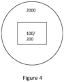
- FIG 4 schematically depicts a projectile 2000 or munition 2000 comprising the system 100 including the transducer of Figure 1 and the structure of Figures 2 and 3 or the structure 200 of Figures 2 and 3 .
- a projectile means any object that moves freely under the influence of gravity and air resistance - e.g. it does not comprise any propulsion arrangement.
- Munitions are provided in different forms for different applications. Typically, a particular munition will be used for a particular application or intention. Munitions include, but are not limited to, artillery shells and charges, missiles, rockets and mortar rounds, as well as small arms munitions (e.g., bullets). Munitions typically include a charge, and optionally a fuze system for managing the detonation or explosion of that charge.
- the system 100 and structure 200 unlike batteries, can be stored for a long time without their performance being affected. Further advantageously, the system 100 and structure can be accommodated in the constrained space typically available in projectiles and munitions due to their small size. The system 100 and the structure 200 are cheap to manufacture.
- the invention provides an energy harvesting system that facilitates efficient energy harvesting and which is small, stable and robust enough to be used in projectiles and munitions.
- the energy harvesting may be advantageously used to be a power supply, or the sole power supply.
- Launch of a projectile and munition may cause the described transducer to generate power sufficient to perform a function, for example powering or arming a fuze system, without a separate power supply.
- launch of a projectile and munition may actually be detected using the same transducer.
- the embodiments might allow for more efficient power generation, or more sensitive detection, by conversion of compressive forces to distinct shear regions.
- the term “comprising” or “comprises” means including the component(s) specified but not to the exclusion of the presence of other components.
- the term “consisting essentially of” or “consists essentially of” means including the components specified but excluding other components except for materials present as impurities, unavoidable materials present as a result of processes used to provide the components, and components added for a purpose other than achieving the technical effect of the invention, such as colourants, and the like.
Landscapes
- Engineering & Computer Science (AREA)
- General Engineering & Computer Science (AREA)
- Chemical & Material Sciences (AREA)
- Crystallography & Structural Chemistry (AREA)
- General Electrical Machinery Utilizing Piezoelectricity, Electrostriction Or Magnetostriction (AREA)
Abstract
An energy harvesting system, comprising a transducer and a structure 200. The transducer is arranged to provide an output signal in response to deformation of the transducer by an applied force to harvest energy from the applied force. The structure is in mechanical communication with the transducer and extends across the transducer. Deformation of the structure is arranged to cause deformation of the transducer. The mechanical communication is at a number of distinct points 210. Portions 220 of the structure are angled away from being perpendicular to the transducer, whereby a compressive force applied to the structure and transducer is redirected to a shear force on the transducer at the points.
Description
- The invention relates to an energy harvesting system comprising a transducer and a structure in mechanical communication with the transducer.
- Energy harvesting refers to the derivation of energy from external sources. For example, energy harvesting may mean deriving an electrical output from a mechanical input. A transducer is a device that is often used in energy harvesting systems, because it is able to convert energy from one form to another (transduction). Clearly, it is desirable to generate as much energy as possible from a given input, to increase power generation or detection sensitivities. Hence, there is a need for an energy harvesting system that facilitates efficient energy harvesting.
- It is one aim of the present invention, amongst others, to provide an energy harvesting system which at least partially obviates or mitigates at least some of the disadvantages of the prior art, whether identified herein or elsewhere, or to provide an alternative approach. For instance, it is an aim of embodiments of the invention to provide an energy harvesting system that facilitates efficient energy harvesting.
- According to a first aspect, there is provided an energy harvesting system, comprising a transducer and a structure. The transducer is arranged to provide an output signal in response to deformation of the transducer by an applied force to harvest energy from the applied force. The structure is in mechanical communication with the transducer and extends across the transducer, deformation of the structure being arranged to cause deformation of the transducer. The mechanical communication is at a number of distinct points. Portions of the structure are angled away from being perpendicular to the transducer, whereby a compressive force applied to the structure and transducer is redirected to a shear force on the transducer at the points.
- Portions of the structure which are at adjacent points may be angled away from each other.
- The shear force may be directed toward/away from adjacent points.
- Adjacent points may be equally distributed.
- The structure may have a wave-like profile.
- A perimeter of the structure and/or transducer may be circular.
- The structure and/or transducer may have an annular cross-section.
- The structure may be configured to redirect the shear force in circumferential direction.
- The transducer may be piezoelectric or magnetostrictive.
- The transducer may be more efficient under shear force than under compression in terms of providing an output signal in response to deformation of the transducer by an applied force.
- The system may further comprise an electrode arrangement. The configuration of the electrode arrangement may be arranged to map onto the points.
- The output signal may be used for powering an external component and/or detecting a change in state in the energy harvesting system.
- According to a second aspect, there is provided a structure for use in an energy harvesting system, the energy harvesting system comprising a transducer arranged to provide an output signal in response to deformation of the transducer by an applied force to harvest energy from the applied force, the structure being in mechanical communication with the transducer and extending across the transducer, deformation of the structure being arranged to cause deformation of the transducer, wherein the mechanical communication is at a number of distinct points, and wherein portions of the structure are angled away from being perpendicular to the transducer, whereby a compressive force applied to the structure and transducer is redirected to a shear force on the transducer at the points.
- According to a third aspect, there is provided a projectile comprising the system of the first aspect or the structure of the second aspect.
- According to a fourth aspect, there is provided a munition comprising the system of the first aspect or the structure of the second aspect.
- For a better understanding of the invention, and to show how exemplary embodiments of the same may be brought into effect, reference will be made, by way of example only, to the accompanying diagrammatic Figures, in which:
-
Figure 1 schematically depicts a transducer according to an exemplary embodiment; -
Figure 2 schematically depicts a structure for mechanical communication with the transducer according to an exemplary embodiment; -
Figure 3 schematically depicts a side perspective of the structure ofFigure 2 according to an exemplary embodiment; and -
Figure 4 schematically depicts a projectile or munition comprising a system including the transducer ofFigure 1 and the structure ofFigures 2 and 3 or the structure ofFigures 2 and 3 according to an exemplary embodiment. - The energy harvesting system comprises a transducer and a structure. The
transducer 100 is shown inFigure 1 and thestructure 200 is shown inFigures 2 and 3 . Thetransducer 100 and thestructure 200 are shown separately inFigures 1 to 3 , but, as explained below, as part of the energy harvesting system they are typically in physical contact. Thestructure 200 could be integrated in the energy harvesting system or could be a separate part of the energy harvesting system that can be exchanged and replaced. - The
transducer 100 is arranged to provide an output signal. The output signal is outputted in response to deformation of thetransducer 100 by an applied force resulting from a compressive force (indicated by the thick arrows inFigure 2 ) applied to thestructure 200 and transducer 100. Thetransducer 100 typically comprises piezoelectric material, preferably perovskite, or a magnetostrictive material. Advantageously, these materials allow generation of energy in response to an applied force. Piezoelectric materials may be preferred, since they generate power without the need for, e.g. a take-off coil arrangement or similar. Perovskite materials or structures may find particular use in the embodiments discussed here, due to the fact that such materials may be more efficient at energy generation under shear force, compared with compressive force. - The
structure 200, shown separately from thetransducer 100 inFigures 2 and 3 for clarity, is in mechanical communication with thetransducer 100 and extends across thetransducer 100. Being in mechanical communication typically means that thestructure 200 contacts thetransducer 100. For example, thestructure 200 may overlay thetransducer 100. This contact may be mediated by a material in between thetransducer 100 and thestructure 200. As a consequence of the mechanical communication between thestructure 200 and thetransducer 100, deformation of thestructure 200 causes deformation of thetransducer 100. - The mechanical communication is at a number of
distinct points 210. In other words, the mechanical communication between thetransducer 100 and thestructure 200 is atpoints 210 that are spaced apart. For example, thetransducer 100 and thestructure 200 may be in contact only at intervals. - The
structure 200 comprisesportions 220. As shown inFigures 2 and 3 , theportions 220 of thestructure 200 are each angled away from being perpendicular to thetransducer 100. In other words, the angle between each of theportions 220 and thetransducer 100 deviates from 90 degrees. For example, when thestructure 200 is overlaid on the transducer 100 (so that theperimeter 201 of thestructure 200 tracks theperimeter 101 of the transducer 100), each of theportions 220 is at an angle of between 0 degree and 90 degrees with respect to thetransducer 100. As a result of the angled arrangement of theportions 220, the compressive force (indicated by the thick arrows inFigure 2 ) applied to thestructure 200 andtransducer 100 is redirected to a shear force (see thick arrows inFigure 3 ) on thetransducer 100 at thepoints 210. To this end, thetransducer 100 may be more efficient under shear force than under compression in terms of providing an output signal in response to deformation of thetransducer 100 by the applied force. Or, the embodiment might simply provide an alternative to the use of compression, which might be useful. For example, conversion or direction to a shear force, at multiples points, might result in an alternative or improved conversion of mechanical input to energy generation. - In order to enhance the shear force on the
transducer 100, theportions 220 of thestructure 100 which are at adjacent points may be angled away from each other. In other words, theportions 220 of thestructure 220 which are at adjacent points may fan out towards thetransducer 100. In this way, a pinch/pull effect on thetransducer 100 is generated. Similarly, and for the same reasons, the shear force may be directed toward/away from adjacent points.Portions 220 of the structure which are at adjacent points typically means a set of pairs of theportions 220. For instance, inFigure 2 portions portions 220 at adjacent points. - There will likely be radial spready of the
transducer 100 as result of the applied forces, shown by thick radial arrows in the Figure. An annular structure, as shown, might be better at accommodating such spread, compared with a disc or circle structure. For example, having an inner hole or space might prevent the introduction of odd or unexpected forces, or buckling, at the central region of the transducer. This is also discussed below. - Adjacent points may be equally distributed. For example, the adjacent points may be separated by equal (i.e., regular) intervals. Advantageously, this arrangement of the
adjacent points 210 results in the shear force on thetransducer 100 being uniformly distributed. Similarly, uniform distribution of the shear force on thetransducer 100 may be facilitated by thestructure 200 having a wave-like profile. A wave-like profile is also advantageous as it is easy to manufacture. - The
perimeter 201 of thestructure 200 and/or theperimeter 101 of thetransducer 100 may be circular (i.e., thestructure 200 and/or thetransducer 100 may be disc shaped), as shown inFigures 1 to 3 . In other words, the outline of thestructure 200 and/ortransducer 100 may be circular. Advantageously, the absence of corners engenders predictability of the direction of the shear force. A cross-section of thestructure 200 and/ortransducer 100 may be annular. In other words, thestructure 200 and/ortransducer 100 may have a circular outline with a cavity (e.g., a cylindrical cavity) along its or their central axis. Advantageously, in addition the absence of corners engendering predictability of the direction of the shear force, an annular cross-section facilitates flexibility of thestructure 200 and/ortransducer 100 and enables thestructure 200 and/ortransducer 100 to uniformly expand under compressive force, which may help avoid damage. - The
structure 200 is preferably configured to redirect the shear force in circumferential direction. Advantageously, redirecting the shear force in circumferential direction means that the shear force can be applied non-linearly to thetransducer 100, thereby increasing the number of pinch/pull points and hence maximising the energy harvested. A circumferential direction means a direction has a non-radial component (e.g., a tangential component). - The output signal may be used for powering an external component. Instead or additionally, the output signal may be used for detecting a change in state in the energy harvesting system. Consequently, the energy harvesting system may be used for power generation or as a sensor. Power generation may be more efficient. Similarly, the sensor may be more sensitive.
- Although not shown in the Figures, the system will typically comprise an electrode arrangement, for use in taking power from the transducer. This could be part of the transducer, or connected to the transducer. As discussed above, the use of distinct contact points is advantageous. The configuration of the electrode arrangement may be arranged to map onto the points. This might mean that the electrode arrangement is shaped or formed, or has one or more electrodes, that are linked to the location, shape, or area of the distinct points. For example, having one or more electrodes or electrode regions in the vicinity of the distinct points (e.g. where the shear forces are introduced) might allow for more efficient or effective energy harvesting at (e.g. taking power from) those points, or areas near those points, or between adjacent points.
-
Figure 4 schematically depicts a projectile 2000 ormunition 2000 comprising thesystem 100 including the transducer ofFigure 1 and the structure ofFigures 2 and 3 or thestructure 200 ofFigures 2 and 3 . A projectile means any object that moves freely under the influence of gravity and air resistance - e.g. it does not comprise any propulsion arrangement. Munitions are provided in different forms for different applications. Typically, a particular munition will be used for a particular application or intention. Munitions include, but are not limited to, artillery shells and charges, missiles, rockets and mortar rounds, as well as small arms munitions (e.g., bullets). Munitions typically include a charge, and optionally a fuze system for managing the detonation or explosion of that charge. Advantageously, thesystem 100 andstructure 200, unlike batteries, can be stored for a long time without their performance being affected. Further advantageously, thesystem 100 and structure can be accommodated in the constrained space typically available in projectiles and munitions due to their small size. Thesystem 100 and thestructure 200 are cheap to manufacture. - In summary, the invention provides an energy harvesting system that facilitates efficient energy harvesting and which is small, stable and robust enough to be used in projectiles and munitions. In these particular applications, the energy harvesting may be advantageously used to be a power supply, or the sole power supply. Launch of a projectile and munition may cause the described transducer to generate power sufficient to perform a function, for example powering or arming a fuze system, without a separate power supply. Alternatively or additionally, launch of a projectile and munition may actually be detected using the same transducer. As described above, the embodiments might allow for more efficient power generation, or more sensitive detection, by conversion of compressive forces to distinct shear regions.
- All of the features disclosed in this specification (including any accompanying claims and drawings), and/or all of the steps of any method or process so disclosed, may be combined in any combination, except combinations where at most some of such features and/or steps are mutually exclusive.
- Each feature disclosed in this specification (including any accompanying claims, and drawings) may be replaced by alternative features serving the same, equivalent or similar purpose, unless expressly stated otherwise. Thus, unless expressly stated otherwise, each feature disclosed is one example only of a generic series of equivalent or similar features.
- Throughout this specification, the term "comprising" or "comprises" means including the component(s) specified but not to the exclusion of the presence of other components. The term "consisting essentially of" or "consists essentially of" means including the components specified but excluding other components except for materials present as impurities, unavoidable materials present as a result of processes used to provide the components, and components added for a purpose other than achieving the technical effect of the invention, such as colourants, and the like.
- The term "consisting of" or "consists of" means including the components specified but excluding other components.
- Whenever appropriate, depending upon the context, the use of the term "comprises" or "comprising" may also be taken to include the meaning "consists essentially of" or "consisting essentially of", and also may also be taken to include the meaning "consists of" or "consisting of".
- The optional features set out herein may be used either individually or in combination with each other where appropriate and particularly in the combinations as set out in the accompanying claims. The optional features for each aspect or exemplary embodiment of the invention, as set out herein are also applicable to all other aspects or exemplary embodiments of the invention, where appropriate. In other words, the skilled person reading this specification should consider the optional features for each aspect or exemplary embodiment of the invention as interchangeable and combinable between different aspects and exemplary embodiments.
Claims (15)
- An energy harvesting system, comprising:a transducer arranged to provide an output signal in response to deformation of the transducer by an applied force to harvest energy from the applied force;a structure in mechanical communication with the transducer and extending across the transducer, deformation of the structure being arranged to cause deformation of the transducer,wherein the mechanical communication is at a number of distinct points, andwherein portions of the structure are angled away from being perpendicular to the transducer, whereby a compressive force applied to the structure and transducer is redirected to a shear force on the transducer at the points.
- The system of claim 1, wherein the portions of the structure which are at adjacent points are angled away from each other.
- The system of any preceding claim, wherein the shear force is directed toward/away from adjacent points.
- The system of any preceding claim, wherein adjacent points are equally distributed.
- The system of any preceding claims, wherein the structure has a wave-like profile.
- The system of any preceding claim, wherein a perimeter of the structure and/or transducer is circular.
- The system of any preceding claim, wherein the structure and/or transducer has an annular cross-section.
- The system of any preceding claim, the structure is configured to redirect the shear force in circumferential direction.
- The system of any preceding claim, wherein the transducer is piezoelectric or magnetostrictive.
- The system of any preceding claim, wherein the transducer is more efficient under shear force than under compression in terms of providing an output signal in response to deformation of the transducer by an applied force.
- The system of any preceding claim, further comprising an electrode arrangement, wherein the configuration of the electrode arrangement is arranged to map onto the points.
- The system of any preceding claim, wherein the output signal is used for powering an external component and/or detecting a change in state in the energy harvesting system.
- A structure for use in an energy harvesting system, the energy harvesting system comprising a transducer arranged to provide an output signal in response to deformation of the transducer by an applied force to harvest energy from the applied force, the structure being in mechanical communication with the transducer and extending across the transducer, deformation of the structure being arranged to cause deformation of the transducer,wherein the mechanical communication is at a number of distinct points, andwherein portions of the structure are angled away from being perpendicular to the transducer, whereby a compressive force applied to the structure and transducer is redirected to a shear force on the transducer at the points.
- A projectile comprising the system or structure of any preceding claim.
- A munition comprising the system or structure of any preceding claim.
Priority Applications (4)
| Application Number | Priority Date | Filing Date | Title |
|---|---|---|---|
| EP22275153.9A EP4382852A1 (en) | 2022-12-05 | 2022-12-05 | Energy harvesting system |
| EP23820994.4A EP4631162A1 (en) | 2022-12-05 | 2023-12-05 | Energy harvesting system |
| PCT/GB2023/053129 WO2024121542A1 (en) | 2022-12-05 | 2023-12-05 | Energy harvesting system |
| AU2023391249A AU2023391249A1 (en) | 2022-12-05 | 2023-12-05 | Energy harvesting system |
Applications Claiming Priority (1)
| Application Number | Priority Date | Filing Date | Title |
|---|---|---|---|
| EP22275153.9A EP4382852A1 (en) | 2022-12-05 | 2022-12-05 | Energy harvesting system |
Publications (1)
| Publication Number | Publication Date |
|---|---|
| EP4382852A1 true EP4382852A1 (en) | 2024-06-12 |
Family
ID=84421542
Family Applications (1)
| Application Number | Title | Priority Date | Filing Date |
|---|---|---|---|
| EP22275153.9A Pending EP4382852A1 (en) | 2022-12-05 | 2022-12-05 | Energy harvesting system |
Country Status (1)
| Country | Link |
|---|---|
| EP (1) | EP4382852A1 (en) |
Citations (2)
| Publication number | Priority date | Publication date | Assignee | Title |
|---|---|---|---|---|
| US20080129151A1 (en) * | 2006-12-02 | 2008-06-05 | Rastegar Jahangir S | Piezoelectric generators for munitions fuzing and the like |
| CN108493328B (en) * | 2018-01-29 | 2021-12-17 | 北京信息科技大学 | Piezoelectric vibrator and transducer based on shearing vibration and bending vibration and manufacturing method |
-
2022
- 2022-12-05 EP EP22275153.9A patent/EP4382852A1/en active Pending
Patent Citations (2)
| Publication number | Priority date | Publication date | Assignee | Title |
|---|---|---|---|---|
| US20080129151A1 (en) * | 2006-12-02 | 2008-06-05 | Rastegar Jahangir S | Piezoelectric generators for munitions fuzing and the like |
| CN108493328B (en) * | 2018-01-29 | 2021-12-17 | 北京信息科技大学 | Piezoelectric vibrator and transducer based on shearing vibration and bending vibration and manufacturing method |
Non-Patent Citations (3)
| Title |
|---|
| ERHART J ET AL: "Piezoelectric composite "shear-moonie" transducer", ANNALES DE CHIMIE SCIENCE DES MATÉRIAUX, vol. 26, no. 1, 1 January 2001 (2001-01-01), Cachan, pages 173 - 176, XP093044739, Retrieved from the Internet <URL:https://www.sciencedirect.com/science/article/pii/S0151910701900327/pdf?md5=426188b17eea66d2740f20ebbc6e7aea&pid=1-s2.0-S0151910701900327-main.pdf> DOI: 10.1016/S0151-9107(01)90032-7 * |
| GAO X ET AL: "High output power density of a shear-mode piezoelectric energy harvester based on Pb(In1/2Nb1/2)O3-Pb(Mg1/3Nb2/3)O3-PbTiO3 single crystals", APPLIED ENERGY, vol. 271, 115193, 28 May 2020 (2020-05-28), XP086175812, ISSN: 0306-2619, [retrieved on 20200528], DOI: 10.1016/J.APENERGY.2020.115193 * |
| QIAO Y ET AL: "Design and Fabrication of an Underwater Transducer Based on the Shear Vibration Mode and Trapezoid Transition Layer", MICROMACHINES, vol. 13, no. 8, 1320, 15 August 2022 (2022-08-15), XP093044733, DOI: 10.3390/mi13081320 * |
Similar Documents
| Publication | Publication Date | Title |
|---|---|---|
| GB2625085A (en) | Energy harvesting system | |
| US3757694A (en) | Fragment core warhead | |
| US3960085A (en) | Variable geometry warhead | |
| US3980019A (en) | Adaptive ordnance system | |
| US3714897A (en) | Directed warhead | |
| AU2023391249A1 (en) | Energy harvesting system | |
| US3196794A (en) | Piezo-electric fuse device | |
| US3720168A (en) | Elliptical warhead | |
| US4723087A (en) | Piezoelectric impact sensor | |
| US11965717B2 (en) | Electromagnetic grenade | |
| US8640624B1 (en) | Low collateral damage air defense projectile | |
| US3388633A (en) | Multi-staged ballistic device | |
| EP4637019A1 (en) | Energy harvesting system, structure, projectile, and munition | |
| EP4637020A1 (en) | Improved energy harvesting system, structure, projectile, and munition | |
| GB2027856A (en) | Explosive fragmentation charges | |
| US4241662A (en) | Electrical projectile detonator | |
| US3470818A (en) | Detonator generator for a spinstabilized projectile | |
| WO2025219688A1 (en) | Energy harvesting system, structure, projectile, and munition | |
| WO2025219687A1 (en) | Improved energy harvesting system, structure, projectile, and munition | |
| GB2640462A (en) | Improved energy harvesting system, structure, projectile, and munition | |
| GB2640461A (en) | Energy harvesting system, structure, Projectile and munition | |
| EP1419359B1 (en) | Ammunition device with two active charges | |
| KR101885730B1 (en) | General purpose electronic safety and arming device with flight environment and target collision detection function | |
| EP0895054B1 (en) | Cover for a shaped charge projectile | |
| US3188960A (en) | Impact switch for missile warhead |
Legal Events
| Date | Code | Title | Description |
|---|---|---|---|
| PUAI | Public reference made under article 153(3) epc to a published international application that has entered the european phase |
Free format text: ORIGINAL CODE: 0009012 |
|
| STAA | Information on the status of an ep patent application or granted ep patent |
Free format text: STATUS: THE APPLICATION HAS BEEN PUBLISHED |
|
| AK | Designated contracting states |
Kind code of ref document: A1 Designated state(s): AL AT BE BG CH CY CZ DE DK EE ES FI FR GB GR HR HU IE IS IT LI LT LU LV MC ME MK MT NL NO PL PT RO RS SE SI SK SM TR |