EP4382745A1 - Windenergieanlage und verfahren zum steuern einer windenergieanlage - Google Patents
Windenergieanlage und verfahren zum steuern einer windenergieanlage Download PDFInfo
- Publication number
- EP4382745A1 EP4382745A1 EP22212206.1A EP22212206A EP4382745A1 EP 4382745 A1 EP4382745 A1 EP 4382745A1 EP 22212206 A EP22212206 A EP 22212206A EP 4382745 A1 EP4382745 A1 EP 4382745A1
- Authority
- EP
- European Patent Office
- Prior art keywords
- temperature
- wind turbine
- dependent
- actuator
- passive
- Prior art date
- Legal status (The legal status is an assumption and is not a legal conclusion. Google has not performed a legal analysis and makes no representation as to the accuracy of the status listed.)
- Granted
Links
Images



Classifications
-
- F—MECHANICAL ENGINEERING; LIGHTING; HEATING; WEAPONS; BLASTING
- F03—MACHINES OR ENGINES FOR LIQUIDS; WIND, SPRING, OR WEIGHT MOTORS; PRODUCING MECHANICAL POWER OR A REACTIVE PROPULSIVE THRUST, NOT OTHERWISE PROVIDED FOR
- F03D—WIND MOTORS
- F03D7/00—Controlling wind motors
- F03D7/02—Controlling wind motors the wind motors having rotation axis substantially parallel to the air flow entering the rotor
- F03D7/04—Automatic control; Regulation
-
- F—MECHANICAL ENGINEERING; LIGHTING; HEATING; WEAPONS; BLASTING
- F03—MACHINES OR ENGINES FOR LIQUIDS; WIND, SPRING, OR WEIGHT MOTORS; PRODUCING MECHANICAL POWER OR A REACTIVE PROPULSIVE THRUST, NOT OTHERWISE PROVIDED FOR
- F03D—WIND MOTORS
- F03D9/00—Adaptations of wind motors for special use; Combinations of wind motors with apparatus driven thereby; Wind motors specially adapted for installation in particular locations
- F03D9/20—Wind motors characterised by the driven apparatus
- F03D9/25—Wind motors characterised by the driven apparatus the apparatus being an electrical generator
-
- F—MECHANICAL ENGINEERING; LIGHTING; HEATING; WEAPONS; BLASTING
- F03—MACHINES OR ENGINES FOR LIQUIDS; WIND, SPRING, OR WEIGHT MOTORS; PRODUCING MECHANICAL POWER OR A REACTIVE PROPULSIVE THRUST, NOT OTHERWISE PROVIDED FOR
- F03D—WIND MOTORS
- F03D1/00—Wind motors with rotation axis substantially parallel to the air flow entering the rotor
- F03D1/101—Nacelles
- F03D1/125—Access thereto, e.g. doors or platforms
-
- F—MECHANICAL ENGINEERING; LIGHTING; HEATING; WEAPONS; BLASTING
- F03—MACHINES OR ENGINES FOR LIQUIDS; WIND, SPRING, OR WEIGHT MOTORS; PRODUCING MECHANICAL POWER OR A REACTIVE PROPULSIVE THRUST, NOT OTHERWISE PROVIDED FOR
- F03D—WIND MOTORS
- F03D13/00—Assembly, mounting or commissioning of wind motors; Arrangements specially adapted for transporting wind motor components
- F03D13/10—Assembly of wind motors; Arrangements for erecting wind motors
-
- F—MECHANICAL ENGINEERING; LIGHTING; HEATING; WEAPONS; BLASTING
- F03—MACHINES OR ENGINES FOR LIQUIDS; WIND, SPRING, OR WEIGHT MOTORS; PRODUCING MECHANICAL POWER OR A REACTIVE PROPULSIVE THRUST, NOT OTHERWISE PROVIDED FOR
- F03D—WIND MOTORS
- F03D80/00—Details, components or accessories not provided for in groups F03D1/00 - F03D17/00
- F03D80/60—Cooling or heating of wind motors
-
- F—MECHANICAL ENGINEERING; LIGHTING; HEATING; WEAPONS; BLASTING
- F03—MACHINES OR ENGINES FOR LIQUIDS; WIND, SPRING, OR WEIGHT MOTORS; PRODUCING MECHANICAL POWER OR A REACTIVE PROPULSIVE THRUST, NOT OTHERWISE PROVIDED FOR
- F03D—WIND MOTORS
- F03D80/00—Details, components or accessories not provided for in groups F03D1/00 - F03D17/00
- F03D80/60—Cooling or heating of wind motors
- F03D80/601—Cooling or heating of wind motors using ambient airflow; Convective cooling of components
-
- F—MECHANICAL ENGINEERING; LIGHTING; HEATING; WEAPONS; BLASTING
- F05—INDEXING SCHEMES RELATING TO ENGINES OR PUMPS IN VARIOUS SUBCLASSES OF CLASSES F01-F04
- F05B—INDEXING SCHEME RELATING TO WIND, SPRING, WEIGHT, INERTIA OR LIKE MOTORS, TO MACHINES OR ENGINES FOR LIQUIDS COVERED BY SUBCLASSES F03B, F03D AND F03G
- F05B2220/00—Application
- F05B2220/30—Application in turbines
-
- F—MECHANICAL ENGINEERING; LIGHTING; HEATING; WEAPONS; BLASTING
- F05—INDEXING SCHEMES RELATING TO ENGINES OR PUMPS IN VARIOUS SUBCLASSES OF CLASSES F01-F04
- F05B—INDEXING SCHEME RELATING TO WIND, SPRING, WEIGHT, INERTIA OR LIKE MOTORS, TO MACHINES OR ENGINES FOR LIQUIDS COVERED BY SUBCLASSES F03B, F03D AND F03G
- F05B2240/00—Components
- F05B2240/10—Stators
- F05B2240/14—Casings, housings, nacelles, gondels or the like, protecting or supporting assemblies there within
-
- F—MECHANICAL ENGINEERING; LIGHTING; HEATING; WEAPONS; BLASTING
- F05—INDEXING SCHEMES RELATING TO ENGINES OR PUMPS IN VARIOUS SUBCLASSES OF CLASSES F01-F04
- F05B—INDEXING SCHEME RELATING TO WIND, SPRING, WEIGHT, INERTIA OR LIKE MOTORS, TO MACHINES OR ENGINES FOR LIQUIDS COVERED BY SUBCLASSES F03B, F03D AND F03G
- F05B2260/00—Function
- F05B2260/20—Heat transfer, e.g. cooling
- F05B2260/232—Heat transfer, e.g. cooling characterised by the cooling medium
-
- F—MECHANICAL ENGINEERING; LIGHTING; HEATING; WEAPONS; BLASTING
- F05—INDEXING SCHEMES RELATING TO ENGINES OR PUMPS IN VARIOUS SUBCLASSES OF CLASSES F01-F04
- F05B—INDEXING SCHEME RELATING TO WIND, SPRING, WEIGHT, INERTIA OR LIKE MOTORS, TO MACHINES OR ENGINES FOR LIQUIDS COVERED BY SUBCLASSES F03B, F03D AND F03G
- F05B2270/00—Control
- F05B2270/30—Control parameters, e.g. input parameters
- F05B2270/303—Temperature
-
- F—MECHANICAL ENGINEERING; LIGHTING; HEATING; WEAPONS; BLASTING
- F05—INDEXING SCHEMES RELATING TO ENGINES OR PUMPS IN VARIOUS SUBCLASSES OF CLASSES F01-F04
- F05B—INDEXING SCHEME RELATING TO WIND, SPRING, WEIGHT, INERTIA OR LIKE MOTORS, TO MACHINES OR ENGINES FOR LIQUIDS COVERED BY SUBCLASSES F03B, F03D AND F03G
- F05B2270/00—Control
- F05B2270/40—Type of control system
- F05B2270/402—Type of control system passive or reactive, e.g. using large wind vanes
-
- Y—GENERAL TAGGING OF NEW TECHNOLOGICAL DEVELOPMENTS; GENERAL TAGGING OF CROSS-SECTIONAL TECHNOLOGIES SPANNING OVER SEVERAL SECTIONS OF THE IPC; TECHNICAL SUBJECTS COVERED BY FORMER USPC CROSS-REFERENCE ART COLLECTIONS [XRACs] AND DIGESTS
- Y02—TECHNOLOGIES OR APPLICATIONS FOR MITIGATION OR ADAPTATION AGAINST CLIMATE CHANGE
- Y02E—REDUCTION OF GREENHOUSE GAS [GHG] EMISSIONS, RELATED TO ENERGY GENERATION, TRANSMISSION OR DISTRIBUTION
- Y02E10/00—Energy generation through renewable energy sources
- Y02E10/70—Wind energy
- Y02E10/72—Wind turbines with rotation axis in wind direction
Definitions
- the present invention relates to a wind turbine and a method for controlling a wind turbine.
- a wind turbine typically has a tower and a nacelle on the tower.
- the nacelle contains the electrical generator as a heat source, as well as other heat sources in the form of power electronics units.
- the power electronics units generate heat losses during operation, particularly when converting the voltage generated by the generator.
- the heat sources in the nacelle must be actively or passively cooled. Active cooling can be either active air cooling or active liquid cooling.
- a wind turbine is provided with a tower and a nacelle with a nacelle housing.
- the nacelle is placed on the tower.
- a cooling flap is provided, which is designed to close an opening in or on the area of the wind turbine to be cooled.
- At least one temperature-dependent passive actuator is designed to actuate and open the cooling flap depending on the temperature in order to enable heat equalization in the area to be cooled by means of the opening.
- the temperature-dependent passive actuator can change its shape and/or length depending on the temperature without external electrical energy.
- An area of the wind turbine (to be cooled) is provided which has an opening which can be closed by a cooling flap.
- the opening can be provided between two areas of the wind turbine which have different heat generation.
- the cooling flap can be opened by a temperature-dependent passive actuator.
- the opening can be provided on an external wall or outside of the wind turbine.
- a wind turbine is therefore provided with a tower and an area to be cooled.
- the area to be cooled can be a nacelle, a tower, a hub and/or another structure of the wind turbine.
- Several heat sources such as the generator and power electronics units can be present in the nacelle.
- the nacelle has a nacelle housing with at least one closable opening or a cooling flap that can be opened.
- This opening serves as a cooling opening.
- heat in the nacelle housing can be dissipated.
- the opening or the cooling flap is actuated by a temperature-dependent passive actuator when a limit temperature is reached. This allows heat that has been generated within the nacelle housing to at least partially escape through the opening. This enables a passively actuated option for cooling the generator and the power electronics units within the nacelle housing.
- the actuator is temperature-dependent and passive, it can open the cooling flap or the opening even when the wind turbine is not connected to the power supply network and/or when no or insufficient energy for active cooling can be drawn from the power supply network due to an operating state of the wind turbine. This can be the case in particular in the event of a network fault, so that the wind turbine cannot feed any power into the power supply network. to which it is connected. Furthermore, the wind turbine can generate energy due to the inertia of the aerodynamic rotor, which is coupled to the generator. This energy can be converted into heat, for example, using a chopper.
- a method for controlling a wind turbine has an area to be cooled (e.g. a nacelle, a tower, a hub and/or another structure with at least one heat source).
- the heat source can be a generator or a power electronics unit within the nacelle. This or another heat source, in particular a chopper, is only activated if there is a fault in the network (fault operating mode), so that the wind turbine cannot supply energy to the energy supply network.
- the nacelle has a nacelle housing with at least one opening which can be closed by a cooling flap.
- a temperature-dependent passive actuator is provided for opening the cooling flap. When a certain limit temperature is reached within the nacelle or at certain points within the nacelle, the passive actuator is activated so that the cooling flap is opened.
- the temperature-dependent passive actuator can have a bi-material element with a first and second material section, which have different thermal expansion coefficients.
- the bi-material section can have two plastics, other materials or material mixtures with different thermal expansion coefficients.
- the actuator can be designed as a cylinder filled with oil, wherein as the temperature increases, the oil in the cylinder expands, which leads to a change in the dimensions of the cylinder, i.e. a change in length, whereby the cooling flap can be opened.
- the battery can be designed as a cylinder that is filled with a material that expands under the influence of heat (e.g. oil). This leads to a longitudinal expansion of the cylinder.
- the temperature-dependent passive actuator can be designed as a melting cylinder.
- a material is provided in the cylinder which melts at a limit temperature and then expands, which leads to a change in the geometry of the melting cylinder, i.e. the length, so that the cooling flap can be opened.
- the actuator which is designed as a bi-metal actuator, has two welded metal sections with different thermal expansion coefficients.
- the oil cylinder actuator has a cylinder filled with oil, whereby the oil expands as the temperature rises. expands.
- the melting cylinder actuator has a cylinder filled with wax, for example, whereby the wax expands as the temperature rises and as it melts.
- the temperature-dependent passive actuator thus provides a safe and short-term option for cooling the heat sources in the nacelle housing without the need for an external energy supply.
- the passive temperature-dependent actuator can be provided for opening and closing a cooling flap in a nacelle housing.
- the cooling flap is changed depending on the temperature.
- a temperature increase within the nacelle can occur in particular in the event of a fault in the wind turbine. In particular, if the wind turbine cannot supply energy to the connected energy supply network but continues to generate energy, this energy must be consumed. This is done, for example, by using a chopper, i.e. by converting the electrical energy into heat. Since the chopper is provided in the nacelle housing, this leads to an increase in the temperature within the nacelle housing.
- the passive temperature-dependent actuator is used by opening the cooling flap so that heat can escape through the opening in the nacelle housing.
- the passive temperature-dependent actuator must be able to operate independently of externally supplied electrical energy, since in the fault case described above the wind turbine cannot draw energy from the energy supply network to control corresponding components.
- the actuator is therefore designed as a passive temperature-dependent actuator. This ensures that the actuator can continue to operate even when there is no electrical energy available to control other components.
- the passive temperature-dependent actuator can also be installed in existing nacelle housings. It can be used to open an existing cooling flap. Alternatively, an opening with a cooling flap must also be provided in the nacelle housing.
- the passive temperature-dependent actuator for opening the cooling flap in the nacelle housing is particularly advantageous if a chopper, which generates heat during operation, is provided in the nacelle housing.
- An area of the wind turbine to be cooled has an opening with a cooling flap that can be opened by a temperature-dependent passive actuator.
- Fig.1 shows a schematic representation of a wind turbine.
- the wind turbine 100 has a tower 102 with a nacelle 200 on the tower.
- the wind turbine has an aerodynamic rotor 106 with a spinner 110 and three rotor blades 108.
- the nacelle 200 has a nacelle housing 210.
- the wind turbine 100 has an electrical generator 300 which is directly or indirectly coupled to the aerodynamic rotor 106. When the aerodynamic rotor 106 rotates, the rotor of the generator 300 is set in motion so that the generator generates electrical energy.
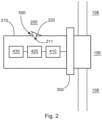
- Fig.2 shows a schematic representation of a nacelle of a wind turbine.
- the nacelle 200 has a nacelle housing 210 and at least one opening 211, which can be closed by a cooling flap 220.
- An electrical generator 300 is coupled directly or indirectly to an aerodynamic rotor 106, wherein the rotor has rotor blades 108.
- the electrical generator 300 is coupled to several power electronics units 410, 420, 430. These three power electronics units 410, 420, 430 are arranged within the nacelle housing 210.
- the power electronics units 410, 420, 430 can, for example, be a rectifier 410, a DC intermediate circuit 420 and a chopper 430.
- further power electronics units can also be arranged in the nacelle housing 210.
- a power electronics unit can, for example, represent an inverter.
- the generator 300 and the power electronics units can generate heat, ie they are heat sources.
- the nacelle can therefore represent an area 200 to be cooled.
- the wind turbine 100 may have a normal operating mode and at least one fault operating mode.
- the aerodynamic rotor 106 rotates and sets a rotor of the generator 300 in motion.
- the electrical generator 300 generates electrical energy, which is output to the first power electronics unit 410, for example for rectification.
- a DC intermediate circuit 420 can be provided.
- the chopper 430 can be used to convert energy generated by the generator, which cannot, however, be fed into the energy supply network, into heat. This can happen in particular in the event of a fault, i.e. in the event of a grid fault. In this case, it may happen that the wind turbine is not allowed to feed any energy into the energy supply network.
- the generator Due to the inertia of the aerodynamic rotor 106, however, it may happen that the generator continues to generate energy. Since this energy cannot be fed into the energy supply network, this energy can be converted into heat in a fault operating mode, for example by the chopper 430.
- the chopper When the chopper is operating, i.e. When electrical energy generated by the generator is converted into heat, a significant increase in temperature within the nacelle housing 210 inevitably occurs. This temperature increase can have a detrimental effect on the power electronics units or other components inside the nacelle housing 210.
- at least one temperature-dependent passive actuator 500 is provided such that it can open the cooling flap 220 at the opening 211 in the nacelle housing 210.
- FIG. 3A A graph is shown to illustrate the expansion of various passive actuators over temperature.
- Fig. 3B shows various examples of the passive actuators.
- Fig. 3A the temperature-dependent expansion of a melting cylinder 530, a bi-metal actuator 510 and an oil cylinder 520 is shown.
- the bi-metal actuator 510 and the oil cylinder actuator 520 each have a linear relationship between increasing temperature and expansion. Only with the melt cylinder actuator 530 is there no linear relationship. Rather, up to a limit value, no significant expansion occurs. Only from the limit value does the cylinder expand with increasing temperature up to a second limit value. Above the second limit value, there is no significant further expansion even with increasing temperature.
- the passive temperature-dependent actuator 500 serves to open an opening 211 in a nacelle housing 210 depending on the temperature.
- the actuator 500 can be designed as a bi-metal actuator 510.
- the bi-metal actuator has a first and second metal section 511, 512, which are made of different materials and have different thermal expansion coefficients. When the temperature increases, the first and second metal sections 511, 512 expand differently, which leads to a change in shape, for example bending or curvature of the bi-metal actuator 510.
- the passive temperature-dependent actuator can be designed as an actuator with an oil cylinder.
- the oil cylinder 520 has a cylinder section 521 and a first and second end 523, 524.
- a heat-expanding material such as oil 522 is provided inside the cylinder 521, which expands when the temperature increases, so that a length of the oil cylinder is increased when the temperature increases. This is shown in Fig.3 shown.
- the passive temperature-dependent actuator can be designed as a melting cylinder 530.
- the melting cylinder 530 has a cylinder 531 and a first and second end 533, 534. Furthermore, a melting material 532 is provided in the cylinder 531. As the temperature increases, the material 532 melts until it is in a liquid state (see right image in Fig. 3B ). This leads to an expansion of the material 532 and thus to a change in the length of the melting cylinder.
- the actuator can at least partially have thermal fins.
- the actuator can be coupled with a heat pipe to better transmit a temperature, for example of the chopper, to the temperature-dependent passive actuator so that a reaction can take place quickly and the cooling flap of the opening is opened.
- Fig. 4A to 4F each show a section of a nacelle of a wind turbine.
- the nacelle housing 210 is shown with a power electronics unit 430, which may have a chopper 430.
- the nacelle housing 210 may be Fig. 4A have an opening (not shown) for active cooling. Active cooling can be operated when sufficient energy is available.
- a nacelle housing with a power electronics unit and a chopper is shown.
- the chopper 440 has a chopper housing 441, optionally with at least one opening 442.
- An opening 211 is provided in the housing 210, which can be closed by a cooling flap 220.
- a temperature-dependent passive actuator 500 is provided, which is coupled to the cooling flap 220 and opens the cooling flap when a corresponding limit temperature is exceeded.
- Fig. 4C is the construction of Fig. 4B , wherein the actuator 510 has a plurality of surface enlargements, e.g. in the form of ribs 510.
- Fig. 4D is based on the design of the nacelle housing of Fig. 4B , wherein a heat pipe or a heat pipe 550 is provided between the chopper and the passive actuator.
- Fig. 4E is a situation like in Fig. 4B shown, wherein an additional opening 211 is provided in the nacelle housing 210 with an additional cooling flap 220. This allows several openings with several cooling flaps to be opened depending on the temperature by the temperature-dependent passive actuators.
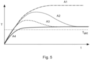
- Fig.5 shows a graph to illustrate the temporal dependence of air temperature in the nacelle for different cooling configurations.
- the case without cooling A1 see Fig. 4A
- a case with openings 211 in the nacelle housing 210 and a cooling flap 200 that can be closed or opened by means of a passive actuator 500 is provided A2 (see Fig. 4B ).
- a ribbed design of the actuator A3 as well as a design with a heat pipe or a heat pipe are shown (see Fig. 4C ).
Landscapes
- Engineering & Computer Science (AREA)
- Life Sciences & Earth Sciences (AREA)
- Sustainable Development (AREA)
- Sustainable Energy (AREA)
- Chemical & Material Sciences (AREA)
- Combustion & Propulsion (AREA)
- Mechanical Engineering (AREA)
- General Engineering & Computer Science (AREA)
- Physics & Mathematics (AREA)
- Thermal Sciences (AREA)
- Power Engineering (AREA)
- Wind Motors (AREA)
Abstract
Description
- Die vorliegende Erfindung betrifft eine Windenergieanlage sowie ein Verfahren zum Steuern einer Windenergieanlage.
- Eine Windenergieanlage weist typischerweise einen Turm und eine Gondel auf dem Turm auf. In der Gondel ist der elektrische Generator als eine Wärmequelle sowie weitere Wärmequellen in Form von Leistungselektronikeinheiten vorgesehen. Insbesondere bei der Umwandlung der durch den Generator erzeugten Spannung erzeugen die Leistungselektronikeinheiten bei ihrem Betrieb Wärmeverluste. Je nach Auslegung der Windenergieanlage und des Generators müssen die Wärmequellen in der Gondel aktiv oder passiv gekühlt werden. Als aktive Kühlung kommt eine aktive Luftkühlung oder eine aktive Flüssigkeitskühlung in Frage.
- Es ist eine Aufgabe der vorliegenden Erfindung, eine Windenergieanlage sowie ein Verfahren zum Steuern einer Windenergieanlage vorzusehen, welches eine verbesserte Kühlung der Windenergieanlage ermöglicht.
- Diese Aufgabe wird durch eine Windenergieanlage nach Anspruch 1 sowie durch ein Verfahren zum Steuern einer Windenergieanlage nach Anspruch 7 gelöst.
- Somit wird eine Windenergieanlage mit einem Turm und einer Gondel mit einem Gondelgehäuse vorgesehen. Die Gondel ist auf dem Turm platziert. Ferner ist eine Kühlklappe vorgesehen, welche dazu ausgestaltet ist, eine Öffnung in oder an dem zu kühlenden Bereich der Windenergieanlage zu verschließen. Mindestens ein temperaturabhängiger passiver Aktor ist dazu ausgestaltet, temperaturabhängig die Kühlklappe zu betätigen und zu öffnen, um einen Wärmeausgleich in dem zu kühlenden Bereich mittels der Öffnung zu ermöglichen. Der temperaturabhängige passive Aktor kann ohne externe elektrische Energie in Abhängigkeit der Temperatur seine Form und/oder seine Länge ändern.
- Es wird ein (zu kühlender) Bereich der Windenergieanlage vorgesehen, der eine Öffnung aufweist, welche durch eine Kühlklappe verschließbar ist. Alternativ dazu kann die Öffnung zwischen zwei Bereichen der Windenergieanlage vorgesehen sein, welche eine unterschiedliche Wärmeentwicklung aufweisen. Die Kühlklappe kann durch einen temperaturabhängigen passiven Aktor geöffnet werden. Die Öffnung kann an einer Außenwand oder Außenseite der Windenergieanlage vorgesehen sein.
- Es wird somit eine Windenergieanlage mit einem Turm und einem zu kühlenden Bereich vorgesehen. Der zu kühlende Bereich kann eine Gondel, einen Turm, eine Nabe und/oder eine andere Struktur der Windenergieanlage darstellen. In der Gondel können mehrere Wärmequellen wie beispielsweise der Generator sowie Leistungselektronikeinheiten vorhanden sein.
- Gemäß einem Aspekt der Erfindung weist die Gondel ein Gondelgehäuse mit mindestens einer verschließbaren Öffnung bzw. einer zu öffnenden Kühlklappe auf. Diese Öffnung dient als Kühlöffnung. Durch Öffnen der Öffnung kann Wärme in dem Gondelgehäuse abgeleitet werden. Die Öffnung bzw. die Kühlklappe wird durch einen temperaturabhängigen passiven Aktuator bei Erreichen einer Grenztemperatur betätigt. Damit kann Wärme, welche innerhalb des Gondelgehäuses erzeugt worden ist, durch die Öffnung zumindest teilweise entweichen. Somit wird eine passiv aktuierbare Möglichkeit der Kühlung des Generators sowie der Leistungselektronikeinheiten innerhalb des Gondelgehäuses ermöglicht. Dadurch, dass der Aktuator temperaturabhängig und passiv ist, kann er auch dann die Kühlklappe oder die Öffnung öffnen, wenn die Windenergieanlage nicht an das Energieversorgungsnetz angeschlossen ist und/oder wenn durch einen Betriebszustand der Windenergieanlage keine oder nicht ausreichend Energie zur aktiven Kühlung aus dem Energieversorgungsnetz entnommen werden kann. Dies kann insbesondere bei einem Netzfehler der Fall sein, so dass die Windenergieanlage keine Leistung in das Energieversorgungsnetz, an welches es angeschlossen ist, abgeben kann. Ferner kann es dazu kommen, dass die Windenergieanlage aufgrund der Trägheit des aerodynamischen Rotors, der mit dem Generator gekoppelt ist, Energie erzeugt. Diese Energie kann beispielsweise mittels eines Choppers in Wärme umgewandelt werden.
- Es wird ein Verfahren zum Steuern einer Windenergieanlage vorgesehen. Die Windenergieanlage weist einen zu kühlenden Bereich (z. B. eine Gondel, einen Turm, eine Nabe und/oder eine andere Struktur mit mindestens einer Wärmequelle) auf. Die Wärmequelle kann einen Generator oder eine Leistungselektronikeinheit innerhalb der Gondel darstellen. Diese oder eine andere Wärmequelle, insbesondere ein Chopper, wird nur dann aktiviert, wenn im Netz ein Fehler vorhanden ist (Fehlerbetriebsart), so dass die Windenergieanlage keine Energie in das Energieversorgungsnetz abgeben kann. Die Gondel weist ein Gondelgehäuse mit mindestens einer Öffnung auf, welche durch eine Kühlklappe verschließbar ist. Zum Öffnen der Kühlklappe ist ein temperaturabhängiger passiver Aktor vorgesehen. Bei Erreichen einer bestimmten Grenztemperatur innerhalb der Gondel oder an bestimmten Stellen innerhalb der Gondel kommt es zu einer Aktivierung des passiven Aktors, so dass die Kühlklappe geöffnet wird.
- Der temperaturabhängige passive Aktor kann ein Bi-Materialelement mit einem ersten und zweiten Materialabschnitt aufweisen, welche unterschiedliche Wärmeausdehnungskoeffizienten aufweisen. Der Bi-Materialabschnitt kann zwei Kunststoffe, anderen Materialien oder Materialmischungen mit unterschiedlichen Wärmeausdehnungskoeffizienten aufweisen. Alternativ dazu kann der Aktor als ein mit Öl gefüllter Zylinder ausgestaltet sein, wobei bei steigender Temperatur das Öl in dem Zylinder sich ausdehnt, was zu einer Änderung der Abmessung des Zylinders, d. h. einer Längenänderung führt, wodurch die Kühlklappe geöffnet werden kann. Alternativ dazu kann der Akku als Zylinder ausgestaltet sein, der mit einem Material befüllt ist, welches sich unter Wärmeeinfluss ausdehnt (z. B. Öl). Dies führt zu einer Längenausdehnung des Zylinders.
- Alternativ dazu kann der temperaturabhängige passive Aktor als ein Schmelzzylinder ausgestaltet sein. In dem Zylinder ist ein Material vorgesehen, welches bei einer Grenztemperatur schmilzt und sich dann ausdehnt, was zu einer Änderung der Geometrie des Schmelzzylinders, d. h. der Länge führt, so dass die Kühlklappe geöffnet werden kann.
- Der Aktor, welcher als Bi-Metall Aktor ausgestaltet ist, weist zwei verschweißte Metallabschnitte mit unterschiedlichen Wärmeausdehnungskoeffizienten auf. Der Ölzylinderaktor weist einem mit Öl gefüllten Zylinder auf, wobei sich das Öl bei steigender Temperatur ausdehnt. Der Schmelzzylinderaktor weist einen beispielsweise mit Wachs gefüllten Zylinder auf, wobei sich das Wachs bei steigender Temperatur und beim Schmelzen ausdehnt.
- Der temperaturabhängige passive Aktuator ermöglicht somit eine sichere und kurzfristig einsetzbare Möglichkeit einer Kühlung der Wärmequellen in dem Gondelgehäuse, ohne dass hierfür eine Energiezufuhr von außen benötigt wird.
- Der passive temperaturabhängige Aktor kann zum Öffnen und Schließen einer Kühlklappe in einem Gondelgehäuse vorgesehen sein. Die Kühlklappe wird temperaturabhängig geändert. Eine Temperaturerhöhung innerhalb der Gondel kann insbesondere in einem Fehlerfall der Windenergieanlage erfolgen. Insbesondere wenn die Windenergieanlage keine Energie an das angeschlossene Energieversorgungsnetz abgeben kann, jedoch weiter Energie erzeugt, muss diese Energie verbraucht werden. Dies erfolgt beispielsweise durch Verwendung eines Choppers, d. h. durch Umwandeln der elektrischen Energie in Wärme. Da der Chopper in dem Gondelgehäuse vorgesehen ist, führt dies zu einer Erhöhung der Temperatur innerhalb des Gondelgehäuses. Um die Temperaturzu begrenzen oderwieder abzusenken, wird der passive temperaturabhängige Aktor verwendet, indem er die Kühlklappe öffnet, so dass Wärme durch die Öffnung in dem Gondelgehäuse entweichen kann. Der passive temperaturabhängige Aktor muss unabhängig von von außen zugeführter elektrischer Energie betreibbar sein, da in dem oben beschriebenen Fehlerfall die Windenergieanlage keine Energie zur Steuerung entsprechender Komponenten aus dem Energieversorgungsnetz entnehmen kann. Daher ist der Aktor als passiver temperaturabhängiger Aktor ausgestaltet. Damit kann erreicht werden, dass der Aktor auch seinen Betrieb sicherstellen kann, wenn keine elektrische Energie zur Steuerung anderer Komponenten vorhanden ist.
- Der passive temperaturabhängige Aktor kann auch in bereits bestehenden Gondelgehäusen eingebaut werden. Er kann dazu verwendet werden, eine bestehende Kühlklappe zu öffnen. Alternativ dazu muss in dem Gondelgehäuse ebenfalls eine Öffnung mit einer Kühlklappe vorgesehen werden.
- Der passive temperaturabhängige Aktor zum Öffnen der Kühlklappe in dem Gondelgehäuse ist insbesondere dann von Vorteil, wenn ein Chopper, der in Betrieb Wärme erzeugt, in dem Gondelgehäuse vorgesehen ist.
- Ein zu kühlender Bereich der Windenergieanlage weist eine Öffnung mit einer Kühlklappe auf, die durch einen temperaturabhängigen passiven Aktor geöffnet werden kann.
- Weitere Ausgestaltungen der Erfindung sind Gegenstand der Unteransprüche.
- Vorteile und Ausführungsbeispiele der Erfindung werden nachstehend unter Bezugnahme auf die Zeichnung näher erläutert.
- Fig. 1
- zeigt eine schematische Darstellung einer Windenergieanlage,
- Fig. 2
- zeigt eine schematische Darstellung einer Gondel einer Windenergie-anlage,
- Fig. 3A
- zeigt einen Graphen zur Veranschaulichung der Ausdehnung von ver-schiedenen passiven Aktoren über die Temperatur,
- Fig. 3B
- zeigt verschiedene passive temperaturabhängige Aktoren,
- Fig. 4A bis 4E
- zeigen jeweils einen Ausschnitt einer Gondel einer Windenergie-anlage mit verschiedenen passiven temperaturabhängigen Aktoren, und
- Fig. 5
- zeigt einen Graphen zur Veranschaulichung einer zeitlichen Abhängig-keit einer Lufttemperatur in der Gondel für verschiedene Ausgestaltun-gen der Kühlung.
-
Fig. 1 zeigt eine schematische Darstellung einer Windenergieanlage. Die Windenergieanlage 100 weist einen Turm 102 mit einer Gondel 200 auf dem Turm auf. Die Windenergieanlage weist einen aerodynamischen Rotor 106 mit einem Spinner 110 und drei Rotorblättern 108 auf. Die Gondel 200 weist ein Gondelgehäuse 210 auf. Die Windenergieanlage 100 weist einen elektrischen Generator 300 auf, welcher direkt oder indirekt mit dem aerodynamischen Rotor 106 gekoppelt ist. Bei Rotation des aerodynamischen Rotors 106 wird der Rotor des Generators 300 in Bewegung versetzt, so dass der Generator elektrische Energie erzeugt. -
Fig. 2 zeigt eine schematische Darstellung einer Gondel einer Windenergieanlage. Die Gondel 200 weist ein Gondelgehäuse 210 und mindestens eine Öffnung 211 auf, welche durch eine Kühlklappe 220 verschlossen werden kann. Ein elektrischer Generator 300 ist direkt oder indirekt mit einem aerodynamischen Rotor 106 gekoppelt, wobei der Rotor Rotorblätter 108 aufweist. Der elektrische Generator 300 ist mit mehreren Leistungselektronikeinheiten 410, 420, 430 gekoppelt. Diese drei Leistungselektronikeinheiten 410, 420, 430 sind innerhalb des Gondelgehäuses 210 angeordnet. Die Leistungselektronikeinheiten 410, 420, 430 können beispielsweise einen Gleichrichter 410, einen DC-Zwischenkreis 420 und einen Chopper 430 darstellen. Alternativ dazu können auch weitere Leistungselektronikeinheiten in dem Gondelgehäuse 210 angeordnet sein. Eine derartige Leistungselektronikeinheit kann beispielsweise einen Wechselrichter darstellen. Beim Betrieb der Windenergieanlage können der Generator 300 und die Leistungselektronikeinheiten Wärme erzeugen, d. h. sie sind Wärmequellen. Die Gondel kann damit einen zu kühlenden Bereich 200 darstellen. - Die Windenergieanlage 100 kann eine Normalbetriebsart und mindestens eine Fehlerbetriebsart aufweisen.
- Beim Betrieb der Windenergieanlage rotiert der aerodynamische Rotor 106 und setzt einen Rotor des Generators 300 in Bewegung. Dadurch erzeugt der elektrische Generator 300 elektrische Energie, welche an die erste Leistungselektronikeinheit 410 beispielsweise zum Gleichrichten ausgegeben wird. Nach der Gleichrichtung durch den Gleichrichter 410 kann ein DC Zwischenkreis 420 vorgesehen sein. Der Chopper 430 kann dazu verwendet werden, durch den Generator erzeugte Energie, welche jedoch nicht an das Energieversorgungsnetz abgegeben werden kann, in Wärme umzuwandeln. Dies kann insbesondere in einem Fehlerfall, d. h. bei einem Netzfehler, erfolgen. Hierbei kann es dazu kommen, dass die Windenergieanlage keine Energie an das Energieversorgungsnetz abgeben darf. Aufgrund der Trägheit des aerodynamischen Rotors 106 kann es jedoch dazu kommen, dass der Generator weiterhin Energie erzeugt. Da diese Energie nicht an das Energieversorgungsnetz abgegeben werden kann, kann diese Energie in einer Fehlerbetriebsart beispielsweise durch den Chopper 430 in Wärme umgewandelt werden. Beim Betrieb des Choppers, d. h. wenn durch den Generator erzeugte elektrische Energie in Wärme umgewandelt wird, kommt es zwangsläufig zu einer erheblichen Erhöhung der Temperatur innerhalb des Gondelgehäuses 210. Diese Temperaturerhöhung kann sich nachteilig auf die Leistungselektronikeinheiten oder andere Komponenten im Inneren des Gondelgehäuses 210 auswirken. Um dies zu verhindern, ist mindestens ein temperaturabhängiger passiver Aktor 500 derart vorgesehen, dass er die Kühlklappe 220 an der Öffnung 211 in dem Gondelgehäuse 210 öffnen kann.
- In
Fig. 3A ist ein Graph zur Veranschaulichung der Ausdehnung von verschiedenen passiven Aktoren über die Temperatur gezeigt.Fig. 3B zeigt verschiedene Beispiele von den passiven Aktoren. InFig. 3A ist die temperaturabhängige Ausdehnung eines Schmelzzylinders 530, eines Bi-Metall Aktors 510 und eines Ölzylinders 520 gezeigt. Der Bi-Metallaktor 510 sowie der Ölzylinderaktor 520 weisen jeweils einen linearen Zusammenhang zwischen steigender Temperatur und Ausdehnung auf. Lediglich bei dem Schmelzzylinderaktor 530 besteht kein linearer Zusammenhang. Vielmehr erfolgt bis zu einem Grenzwert keine nennenswerte Ausdehnung. Erst ab dem Grenzwert erfolgt mit steigender Temperatur eine Ausdehnung des Zylinders bis zu einem zweiten Grenzwert. Oberhalb des zweiten Grenzwertes kommt es auch bei steigender Temperatur nicht zu einer nennenswerten weiteren Ausdehnung. - Der passive temperaturabhängige Aktor 500 dient dazu, eine Öffnung 211 in einem Gondelgehäuse 210 temperaturabhängig zu öffnen. Der Aktor 500 kann als ein Bi-Metallaktor 510 ausgestaltet sein. Dazu weist der Bi-Metallaktor einen ersten und zweiten Metallabschnitt 511, 512 auf, welche aus unterschiedlichem Material hergestellt sind und unterschiedliche Wärmeausdehnungskoeffizienten aufweisen. Bei einer Temperaturerhöhung dehnen sich der erste und zweite Metallabschnitt 511, 512 unterschiedlich aus, was zu einer Formveränderung beispielsweise Biegung bzw. Krümmung des Bi-Metallaktors 510 führt.
- Alternativ dazu kann der passive temperaturabhängige Aktor als Aktor mit einem Ölzylinder ausgestaltet sein. Der Ölzylinder 520 weist einen Zylinderabschnitt 521 und ein erstes und zweites Ende 523, 524 auf. Im Inneren des Zylinders 521 ist ein wärmeausdehnendes Material wie z. B. Öl 522 vorgesehen, welches sich bei Temperaturerhöhung ausdehnt, so dass eine Länge des Ölzylinders bei Temperaturerhöhung vergrößert wird. Dies ist in
Fig. 3 dargestellt. - Ferner kann der passive temperaturabhängige Aktor als Schmelzzylinder 530 ausgestaltet sein. Der Schmelzzylinder 530 weist einen Zylinder 531 und ein erstes und zweites Ende 533, 534 auf. Ferner ist ein Schmelzmaterial 532 in dem Zylinder 531 vorgesehen. Bei zunehmender Temperatur schmilzt das Material 532, bis es sich in einem flüssigen Zustand befindet (s. rechtes Bild in
Fig. 3B ). Dies führt zu einer Ausdehnung des Materials 532 und somit zu einer Längenänderung des Schmelzzylinders. - Zur besseren und schnelleren Aktivierung des temperaturabhängigen passiven Aktors kann der Aktor zumindest teilweise Thermorippen aufweisen. Alternativ dazu kann der Aktor mit einer Heatpipe bzw. einem Wärmerohr gekoppelt sein, um eine Temperatur beispielsweise des Choppers verbessert an den temperaturabhängigen passiven Aktor weiterzuleiten, so dass eine Reaktion schnell erfolgen kann und die Kühlklappe der Öffnung geöffnet wird.
- Damit ist auch eine schnelle Reaktion auf eine überhöhte Temperatur im Inneren des Gondelgehäuses und insbesondere im Bereich des Choppers möglich.
-
Fig. 4A bis 4F zeigen jeweils einen Ausschnitt einer Gondel einer Windenergieanlage. InFig. 4A ist das Gondelgehäuse 210 mit einer Leistungselektronikeinheit 430 gezeigt, welche einen Chopper 430 aufweisen kann. Optional kann das Gondelgehäuse 210 gemäßFig. 4A eine (nicht gezeigte) Öffnung für eine aktive Kühlung aufweisen. Die aktive Kühlung kann betrieben werden, wenn ausreichend Energie vorhanden ist. - In
Fig. 4B ist ein Gondelgehäuse mit einer Leistungselektronikeinheit und einem Chopper gezeigt. Der Chopper 440 weist ein Choppergehäuse 441 optional mit mindestens einer Öffnung 442 auf. In dem Gehäuse 210 ist eine Öffnung 211 vorgesehen, welche durch eine Kühlklappe 220 verschließbar ist. Ferner ist ein temperaturabhängiger passiver Aktor 500 vorgesehen, welcher mit der Kühlklappe 220 gekoppelt ist und die Kühlklappe, wenn eine entsprechende Grenztemperatur überschritten wird, öffnet. - In
Fig. 4C ist der Aufbau vonFig. 4B dargestellt, wobei der Aktor 510 eine Mehrzahl von Oberflächenvergrößerungen z. B. in Form von Rippen 510 aufweist. -
Fig. 4D beruht auf der Ausgestaltung des Gondelgehäuses vonFig. 4B , wobei zwischen dem Chopper und dem passiven Aktor eine Heatpipe oder ein Wärmerohr 550 vorgesehen ist. - In
Fig. 4E ist eine Situation wie inFig. 4B gezeigt, wobei eine zusätzliche Öffnung 211 in dem Gondelgehäuse 210 mit einer zusätzlichen Kühlklappe 220 vorgesehen ist. Damit können mehrere Öffnungen mit mehreren Kühlklappen temperaturabhängig durch die temperaturabhängigen passiven Aktoren geöffnet werden. -
Fig. 5 zeigt einen Graphen zur Veranschaulichung einer zeitlichen Abhängigkeit einer Lufttemperatur in der Gondel für verschiedene Ausgestaltungen der Kühlung. Insbesondere ist der Fall ohne Kühlung A1 (s.Fig. 4A ), ein Fall mit Öffnungen 211 in dem Gondelgehäuse 210 und einer mittels eines passiven Aktors 500 verschließbaren oder zu öffnenden Kühlklappe 200 vorgesehen A2 (s.Fig. 4B ). Ferner ist eine gerippte Ausgestaltung des Aktors A3 sowie eine Ausgestaltung mit einer Heatpipe bzw. einem Wärmerohr dargestellt (s.Fig. 4C ). -
- 100
- Windenergieanlage
- 102
- Turm
- 106
- Rotor
- 108
- Rotorblätter
- 110
- Spinner
- 200
- Gondel
- 210
- Gondelgehäuse
- 211
- Öffnung
- 220
- Kühlklappe
- 300
- Generator
- 410
- Leistungselektronikeinheiten
- 420
- Leistungselektronikeinheiten
- 430
- Leistungselektronikeinheiten
- 440
- Chopper
- 441
- Choppergehäuse
- 442
- Öffnung
- 500
- passiver Aktor
- 510
- Bi-Metallaktor
- 511
- erster Metallabschnitt
- 512
- zweiter Metallabschnitt
- 520
- Ölzylinder
- 521
- Zylinderabschnitt
- 522
- Öl
- 523
- erstes Ende
- 524
- zweites Ende
- 530
- Schmelzzylinder
- 531
- Zylinder
- 532
- Schmelzmaterial
- 533
- erstes Ende
- 534
- zweites Ende
- 550
- Wärmerohr
Claims (9)
- Windenergieanlage (100), miteinem Turm (102),einer Gondel (200) mit einem Gondelgehäuse (210), welches auf dem Turm (102) platziert ist,mindestens einer Kühlklappe (220), welche dazu ausgestaltet ist, eine Öffnung (211) in oder an einem zu kühlenden Bereich (200) der Windenergieanlage (100) zu verschließen,mindestens einem temperaturabhängigen passiven Aktor (500), der dazu ausgestaltet ist, temperaturabhängig die Kühlklappe (200) zu betätigen und zu öffnen, um einen Wärmeausgleich in dem zu kühlenden Bereich (200) mittels der Öffnung (211) zu ermöglichen,wobei der temperaturabhängige passive Aktor (500) ohne externe elektrische Energie in Abhängigkeit der Temperatur seine Form und/oder seine Länge ändert.
- Windenergieanlage (100) nach Anspruch 1,
wobei der Bereich (200) der Windenergieanlage (100) als das Gondelgehäuse (210) mit mindestens einer Öffnung (211) ausgestaltet ist, welche mittels der Kühlklappe (220) verschließbar ist. - Windenergieanlage (100) nach Anspruch 1 oder 2, wobeidie Windenergieanlage (100) eine erste Betriebsart, nämlich eine Normalbetriebsart, und eine zweite Betriebsart, nämlich eine Fehlerbetriebsart, bei welcher die Windenergieanlage (100) nicht an ein Energieversorgungsnetz angeschlossen ist und/oder nicht genügend Energie zu einer aktiven Kühlung zugeführt wird oder bei der eine Temperatur in dem Bereich (200) der Windenergieanlage (100) einen Grenzwert überschreitet, aufweist,wobei der temperaturabhängige passive Aktor (500) dazu ausgestaltet ist, in der Fehlerbetriebsart die mindestens eine Kühlklappe (220) temperaturabhängig zu öffnen, um den Wärmeausgleich in dem Bereich (200) der Windenergieanlage (100) zu ermöglichen.
- Windenergieanlage (100) nach Anspruch 1 bis 3, wobeidas Gondelgehäuse (210) mindestens eine Wärmequelle in Form eines elektrischen Generators (300) und/oder einer Leistungselektronikeinheit (400) aufweist, wobei mindestens eine Leistungselektronikeinheit (400) in einer Fehlerbetriebsart eine Wärmemenge erzeugt, welche größer als ein Schwellwert ist,wobei der passive temperaturabhängige Aktor (500) dazu ausgestaltet ist, die Kühlklappe (200) in Abhängigkeit der durch die Leistungselektronikeinheit (400) erzeugten Wärme zu öffnen.
- Windenergieanlage (100) nach einem der Ansprüche 1 bis 4, wobei
der passive temperaturabhängige Aktor (500) als ein Bi-Metallaktor (510), als ein Ölzylinder (520) mit einer temperaturabhängigen Ausdehnung oder als ein Schmelzzylinder (530) mit einer temperaturabhängigen Ausdehnung ausgestaltet ist. - Windenergieanlage (100) nach einem der Ansprüche 1 bis 5, wobei
der passive temperaturabhängige Aktor (500) eine Oberflächenvergrößerung (540) an seiner Oberfläche zur Verbesserung eines Wärmeaustauschs aufweist. - Windenergieanlage (100) nach einem der Ansprüche 1 bis 6, ferner mit
einem Wärmerohr (550) zwischen einer Wärmequelle und dem passiven temperaturabhängigen Aktor (500). - Verfahren zum Steuern einer Windenergieanlage (100), wobei die Windenergieanlage einen Turm (102), eine Gondel (200) und einen Bereich mit einer Öffnung (211) und mindestens einer Kühlklappe (220) vzum Verschließen der Öffnung aufweist, wobei ein passiver temperaturabhängiger Aktor (500) an der Kühlklappe (220) vorgesehen ist, mit den Schritten:temperaturabhängiges Aktivieren des passiven temperaturabhängigen Aktors (500), undÖffnen der Kühlklappe (200) durch eine temperaturabhängige Längenausdehnung oder Formänderung des passiven temperaturabhängigen Aktors (500),um einen Wärmeausgleich in dem Bereich (200) der Windenergieanlage (100) zu ermöglichen.
- Verfahren nach Anspruch 8, wobei
der passive temperaturabhängige Aktor (500) in einer Fehlerbetriebsart aktivierbar ist, bei welcher die Windenergieanlage keine elektrische Energie an ein Energieversorgungsnetz abgeben oder von dem Energieversorgungsnetz beziehen kann.
Priority Applications (3)
| Application Number | Priority Date | Filing Date | Title |
|---|---|---|---|
| EP22212206.1A EP4382745B1 (de) | 2022-12-08 | 2022-12-08 | Windenergieanlage und verfahren zum steuern einer windenergieanlage |
| CN202311651863.0A CN118167550A (zh) | 2022-12-08 | 2023-12-05 | 风能设备和用于控制风能设备的方法 |
| US18/531,493 US12429028B2 (en) | 2022-12-08 | 2023-12-06 | Wind turbine and method for controlling a wind turbine |
Applications Claiming Priority (1)
| Application Number | Priority Date | Filing Date | Title |
|---|---|---|---|
| EP22212206.1A EP4382745B1 (de) | 2022-12-08 | 2022-12-08 | Windenergieanlage und verfahren zum steuern einer windenergieanlage |
Publications (3)
| Publication Number | Publication Date |
|---|---|
| EP4382745A1 true EP4382745A1 (de) | 2024-06-12 |
| EP4382745C0 EP4382745C0 (de) | 2025-07-30 |
| EP4382745B1 EP4382745B1 (de) | 2025-07-30 |
Family
ID=84462657
Family Applications (1)
| Application Number | Title | Priority Date | Filing Date |
|---|---|---|---|
| EP22212206.1A Active EP4382745B1 (de) | 2022-12-08 | 2022-12-08 | Windenergieanlage und verfahren zum steuern einer windenergieanlage |
Country Status (3)
| Country | Link |
|---|---|
| US (1) | US12429028B2 (de) |
| EP (1) | EP4382745B1 (de) |
| CN (1) | CN118167550A (de) |
Families Citing this family (1)
| Publication number | Priority date | Publication date | Assignee | Title |
|---|---|---|---|---|
| CN119712467A (zh) * | 2025-01-06 | 2025-03-28 | 南通贝卡迪电力科技有限公司 | 一种混合励磁海上风电发电系统及方法 |
Citations (2)
| Publication number | Priority date | Publication date | Assignee | Title |
|---|---|---|---|---|
| DE102007016577A1 (de) * | 2007-04-07 | 2008-10-09 | Robert Bosch Gmbh | Windenergieanlage |
| EP2218909A2 (de) * | 2009-02-17 | 2010-08-18 | Schwieger, Hartwig | Windkraftanlage |
Family Cites Families (12)
| Publication number | Priority date | Publication date | Assignee | Title |
|---|---|---|---|---|
| US4924826A (en) * | 1989-04-27 | 1990-05-15 | Vinson Paul S | Temperature responsive engine compartment |
| US5984196A (en) * | 1997-09-18 | 1999-11-16 | Godsey; Edward L. | Thermal rotary vent |
| US7559391B2 (en) * | 2006-02-28 | 2009-07-14 | International Truck Intellectual Property Company, Llc | Engine compartment temperature sensitive louvers |
| JP4796009B2 (ja) * | 2007-05-18 | 2011-10-19 | 三菱重工業株式会社 | 風力発電装置 |
| JP5123780B2 (ja) * | 2008-07-28 | 2013-01-23 | 三菱重工業株式会社 | 風力発電装置 |
| JP5072994B2 (ja) * | 2010-03-17 | 2012-11-14 | 三菱重工業株式会社 | 風力発電装置 |
| US20130255796A1 (en) * | 2012-03-30 | 2013-10-03 | General Electric Company | Flow-control device, component having a flow-control device, and method of producing a flow-control device |
| EP2806542B1 (de) * | 2013-05-22 | 2016-09-14 | Siemens Aktiengesellschaft | Luftströmungskontrollanordnung |
| EP3194768A1 (de) * | 2014-09-15 | 2017-07-26 | Koninklijke Philips N.V. | Wärmeempfindliche aktuatorvorrichtung |
| US10264782B2 (en) * | 2015-07-16 | 2019-04-23 | Mhi Vestas Offshore Wind A/S | Cooling panel assembly for a wind turbine tower and a wind turbine tower |
| EP4306797B1 (de) * | 2022-07-12 | 2025-04-30 | Wobben Properties GmbH | Windenergieanlagen-rotorblatt und windenergieanlage |
| EP4325050A1 (de) * | 2022-08-18 | 2024-02-21 | Nordex Energy SE & Co. KG | Verfahren zum betrieb einer windturbine, kühlsystem und windturbine |
-
2022
- 2022-12-08 EP EP22212206.1A patent/EP4382745B1/de active Active
-
2023
- 2023-12-05 CN CN202311651863.0A patent/CN118167550A/zh not_active Withdrawn
- 2023-12-06 US US18/531,493 patent/US12429028B2/en active Active
Patent Citations (2)
| Publication number | Priority date | Publication date | Assignee | Title |
|---|---|---|---|---|
| DE102007016577A1 (de) * | 2007-04-07 | 2008-10-09 | Robert Bosch Gmbh | Windenergieanlage |
| EP2218909A2 (de) * | 2009-02-17 | 2010-08-18 | Schwieger, Hartwig | Windkraftanlage |
Also Published As
| Publication number | Publication date |
|---|---|
| EP4382745C0 (de) | 2025-07-30 |
| US12429028B2 (en) | 2025-09-30 |
| CN118167550A (zh) | 2024-06-11 |
| EP4382745B1 (de) | 2025-07-30 |
| US20240191690A1 (en) | 2024-06-13 |
Similar Documents
| Publication | Publication Date | Title |
|---|---|---|
| EP2457320B1 (de) | Verfahren zum betreiben einer windturbine sowie dazu geeignete windturbine | |
| EP2434148B1 (de) | Windenergieanlage | |
| DE19932394C2 (de) | Windenergieanlage mit einem geschlossenen Kühlkreislauf | |
| EP1525396B1 (de) | Windturbine mit einem geschlossenen kühlkreislauf | |
| EP3084943B1 (de) | Photovoltaik wechselrichter mit vorgeschaltetem dc/dc wandler und temperaturregelung der leistungshalbleiter | |
| DE2647136A1 (de) | Steuerungssystem fuer turbinenkraftwerk | |
| EP3397859B1 (de) | Windenergieanlage und kühlvorrichtung für eine windenergieanlage | |
| WO2013152850A1 (de) | Lageranordnung sowie verfahren zur einstellung der vorspannung einer lageranordnung | |
| EP2284634B1 (de) | Verfahren und Anordnung zur automatischen Konfigurationsparameterkontrolle bei Windenergieanlagen | |
| EP4382745B1 (de) | Windenergieanlage und verfahren zum steuern einer windenergieanlage | |
| WO2018202772A1 (de) | Windenergieanlage mit überlastfähigem umrichtersystem | |
| EP3926162B1 (de) | Verfahren zum betrieb einer windenergieanlage, steuerungsvorrichtung zum betrieb einer windenergieanlage und windpark | |
| EP2636131B1 (de) | Windenergieanlage mit synchrongenerator sowie langsam drehender synchrongenerator | |
| EP2535570B1 (de) | Windnachführungsanordnung einer Windenergieanlage. | |
| EP3945656A1 (de) | Verfahren zum einspeisen elektrischer leistung mittels einer windenergieanlage | |
| EP2640970B1 (de) | Windenergieanlage und verfahren zum betreiben einer windenergieanlage mit temperaturüberwachung des transformators | |
| EP3033825A1 (de) | Einrichtung zum ablenken von zumindest einem teil eines axial in einem zwischen einem rotor und einem stator einer rotierenden elektrischen maschine angeordneten zwischenraum strömenden kühlfluids | |
| EP4306797B1 (de) | Windenergieanlagen-rotorblatt und windenergieanlage | |
| EP3555463B1 (de) | Verfahren und vorrichtung zum betreiben von windenergieanlagen | |
| EP3317533B1 (de) | Windenergieanlage und kühlvorrichtung für eine windenergieanlage | |
| EP4191053B1 (de) | Windenergieanlagen-rotorblatt | |
| EP4009161A1 (de) | Verfahren zum aktualisieren einer software oder einer konfiguration einer komponente eines windparks sowie windpark und system | |
| WO2025021440A1 (de) | Verfahren zum betreiben einer anlage | |
| WO2007113012A1 (de) | Hochstrom-leitungsanordnung und generatoranlage | |
| DE102013109958A1 (de) | Photovoltaikanlage und Verfahren zum Bereitstellen von Regelleistung durch eine Photovoltaikanlage |
Legal Events
| Date | Code | Title | Description |
|---|---|---|---|
| PUAI | Public reference made under article 153(3) epc to a published international application that has entered the european phase |
Free format text: ORIGINAL CODE: 0009012 |
|
| STAA | Information on the status of an ep patent application or granted ep patent |
Free format text: STATUS: THE APPLICATION HAS BEEN PUBLISHED |
|
| AK | Designated contracting states |
Kind code of ref document: A1 Designated state(s): AL AT BE BG CH CY CZ DE DK EE ES FI FR GB GR HR HU IE IS IT LI LT LU LV MC ME MK MT NL NO PL PT RO RS SE SI SK SM TR |
|
| STAA | Information on the status of an ep patent application or granted ep patent |
Free format text: STATUS: REQUEST FOR EXAMINATION WAS MADE |
|
| 17P | Request for examination filed |
Effective date: 20241212 |
|
| GRAP | Despatch of communication of intention to grant a patent |
Free format text: ORIGINAL CODE: EPIDOSNIGR1 |
|
| STAA | Information on the status of an ep patent application or granted ep patent |
Free format text: STATUS: GRANT OF PATENT IS INTENDED |
|
| INTG | Intention to grant announced |
Effective date: 20250425 |
|
| GRAS | Grant fee paid |
Free format text: ORIGINAL CODE: EPIDOSNIGR3 |
|
| GRAA | (expected) grant |
Free format text: ORIGINAL CODE: 0009210 |
|
| STAA | Information on the status of an ep patent application or granted ep patent |
Free format text: STATUS: THE PATENT HAS BEEN GRANTED |
|
| AK | Designated contracting states |
Kind code of ref document: B1 Designated state(s): AL AT BE BG CH CY CZ DE DK EE ES FI FR GB GR HR HU IE IS IT LI LT LU LV MC ME MK MT NL NO PL PT RO RS SE SI SK SM TR |
|
| REG | Reference to a national code |
Ref country code: GB Ref legal event code: FG4D Free format text: NOT ENGLISH |
|
| RIN1 | Information on inventor provided before grant (corrected) |
Inventor name: ARNOLD, MATTHIAS Inventor name: BUSEMANN, STEFFEN Inventor name: DABOUL, HUSSAM |
|
| REG | Reference to a national code |
Ref country code: CH Ref legal event code: EP |
|
| REG | Reference to a national code |
Ref country code: DE Ref legal event code: R096 Ref document number: 502022004825 Country of ref document: DE |
|
| REG | Reference to a national code |
Ref country code: IE Ref legal event code: FG4D Free format text: LANGUAGE OF EP DOCUMENT: GERMAN |
|
| U01 | Request for unitary effect filed |
Effective date: 20250730 |
|
| U07 | Unitary effect registered |
Designated state(s): AT BE BG DE DK EE FI FR IT LT LU LV MT NL PT RO SE SI Effective date: 20250805 |
|
| U20 | Renewal fee for the european patent with unitary effect paid |
Year of fee payment: 4 Effective date: 20251128 |
|
| PG25 | Lapsed in a contracting state [announced via postgrant information from national office to epo] |
Ref country code: IS Free format text: LAPSE BECAUSE OF FAILURE TO SUBMIT A TRANSLATION OF THE DESCRIPTION OR TO PAY THE FEE WITHIN THE PRESCRIBED TIME-LIMIT Effective date: 20251130 |
|
| PG25 | Lapsed in a contracting state [announced via postgrant information from national office to epo] |
Ref country code: NO Free format text: LAPSE BECAUSE OF FAILURE TO SUBMIT A TRANSLATION OF THE DESCRIPTION OR TO PAY THE FEE WITHIN THE PRESCRIBED TIME-LIMIT Effective date: 20251030 |
|
| PG25 | Lapsed in a contracting state [announced via postgrant information from national office to epo] |
Ref country code: HR Free format text: LAPSE BECAUSE OF FAILURE TO SUBMIT A TRANSLATION OF THE DESCRIPTION OR TO PAY THE FEE WITHIN THE PRESCRIBED TIME-LIMIT Effective date: 20250730 |
|
| PG25 | Lapsed in a contracting state [announced via postgrant information from national office to epo] |
Ref country code: GR Free format text: LAPSE BECAUSE OF FAILURE TO SUBMIT A TRANSLATION OF THE DESCRIPTION OR TO PAY THE FEE WITHIN THE PRESCRIBED TIME-LIMIT Effective date: 20251031 |
|
| PG25 | Lapsed in a contracting state [announced via postgrant information from national office to epo] |
Ref country code: PL Free format text: LAPSE BECAUSE OF FAILURE TO SUBMIT A TRANSLATION OF THE DESCRIPTION OR TO PAY THE FEE WITHIN THE PRESCRIBED TIME-LIMIT Effective date: 20250730 |
|
| PG25 | Lapsed in a contracting state [announced via postgrant information from national office to epo] |
Ref country code: RS Free format text: LAPSE BECAUSE OF FAILURE TO SUBMIT A TRANSLATION OF THE DESCRIPTION OR TO PAY THE FEE WITHIN THE PRESCRIBED TIME-LIMIT Effective date: 20251030 |
|
| PG25 | Lapsed in a contracting state [announced via postgrant information from national office to epo] |
Ref country code: ES Free format text: LAPSE BECAUSE OF FAILURE TO SUBMIT A TRANSLATION OF THE DESCRIPTION OR TO PAY THE FEE WITHIN THE PRESCRIBED TIME-LIMIT Effective date: 20250730 |
|
| PG25 | Lapsed in a contracting state [announced via postgrant information from national office to epo] |
Ref country code: SM Free format text: LAPSE BECAUSE OF FAILURE TO SUBMIT A TRANSLATION OF THE DESCRIPTION OR TO PAY THE FEE WITHIN THE PRESCRIBED TIME-LIMIT Effective date: 20250730 |
|
| PG25 | Lapsed in a contracting state [announced via postgrant information from national office to epo] |
Ref country code: CZ Free format text: LAPSE BECAUSE OF FAILURE TO SUBMIT A TRANSLATION OF THE DESCRIPTION OR TO PAY THE FEE WITHIN THE PRESCRIBED TIME-LIMIT Effective date: 20250730 |
|
| PG25 | Lapsed in a contracting state [announced via postgrant information from national office to epo] |
Ref country code: SK Free format text: LAPSE BECAUSE OF FAILURE TO SUBMIT A TRANSLATION OF THE DESCRIPTION OR TO PAY THE FEE WITHIN THE PRESCRIBED TIME-LIMIT Effective date: 20250730 |